


As the demand for reliable internet connectivity continues to grow, businesses increasingly turn to multi-WAN solutions to manage their connections and ensure uninterrupted productivity, even during internet outages.
This guide explains how to configure Load Balancing, Backup, and Standby using multiple WAN or VPN interfaces on Grandstream routers. These features are essential for maintaining stable and redundant internet connections, especially when sourced from multiple ISPs, ensuring consistent and reliable access to the internet.
Overview
The Policy Routes feature empowers network administrators to define advanced routing rules for efficient traffic management across multiple WAN/VPN interfaces. This feature offers three modes: Load Balance, Backup, and Standby. Each mode plays a vital role in improving network performance, ensuring uninterrupted connectivity, and providing granular traffic control. Additionally, these policies can be applied to specific VLANs, enabling tailored traffic management for diverse network requirements.
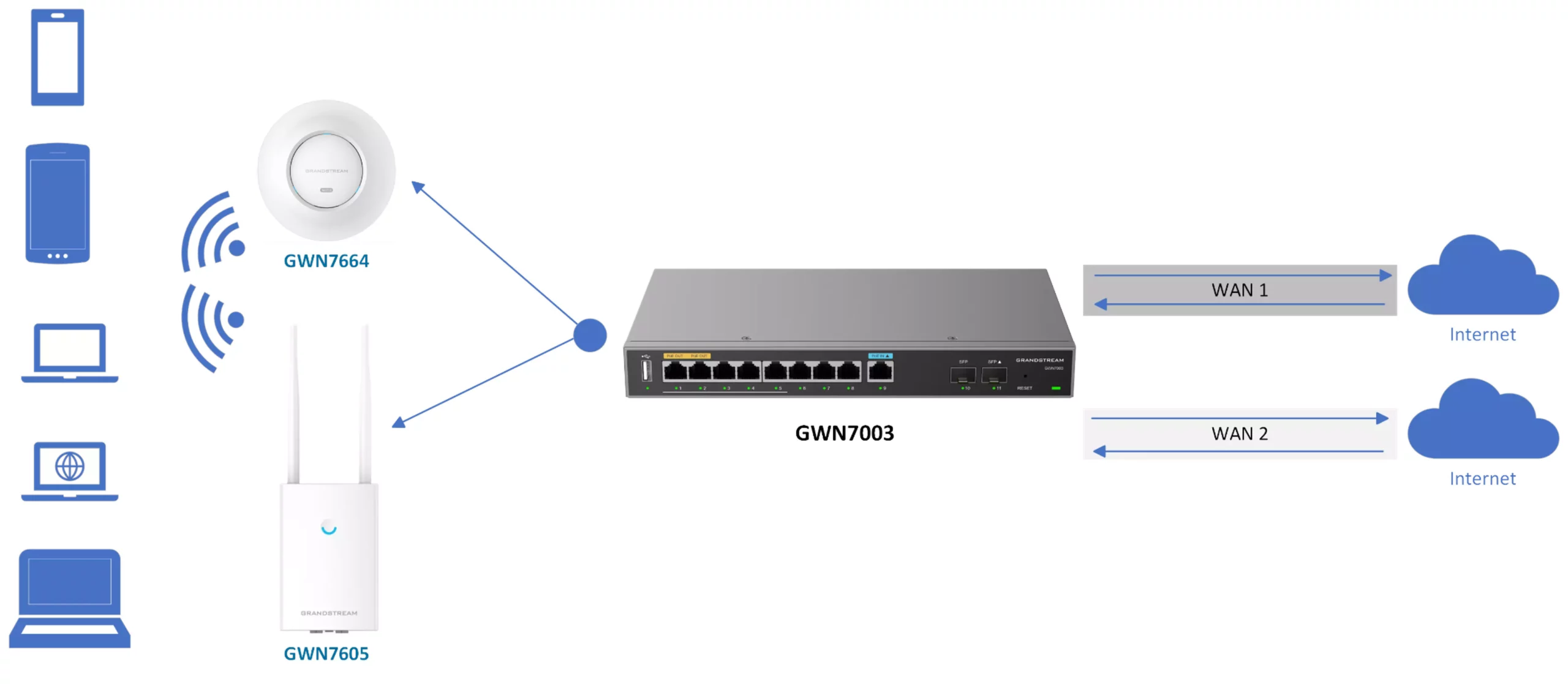
To follow this guide, users should ensure a network topology similar to the one shown below. Ideally, the router should be connected to two different uplinks, such as connections from separate ISPs. The router will manage both uplinks using the Multi-WAN feature, as illustrated in the accompanying diagram:
Prerequisites
Supported Models
The models listed below are compatible with the Route Policy feature. To follow the configuration steps in this guide, ensure you are using one of the supported devices.
| Model | Supported |
|---|---|
| GCC6000 Series | Yes |
| GWN70xx Series | Yes |
| GWN7062/GWN7052(F) Series | Yes |
Multi-WAN Ports Configuration
When implementing Load Balance on the router, both WAN Ports will be used and will share the bandwidth of both Internet connections, instead of using only one single uplink.
In the case of Backup or Standby, one WAN will be used. If it goes down, then the router will switch to the other WAN port automatically.
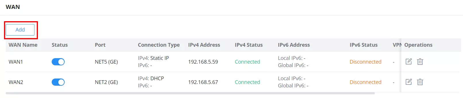
To enable or add another WAN, please do the following:
- Access the device’s Web GUI from a computer connected to a LAN port, and navigate to Network Settings → WAN. (This path may vary depending on the device model.)
- Click on the “Add” button to add another WAN or enable the WAN if it’s already added, as shown below:
Load Balance Mode
- Purpose: Distribute traffic evenly or proportionally across multiple WAN interfaces based on bandwidth capacity or network requirements.
- How It Works:
- Configure weights for each WAN interface. For instance, if two WAN ports have weights of 1 and 2, traffic will be divided in a 1:2 ratio. Similarly, setting weights to 1 and 1 will evenly distribute traffic in a 1:1 ratio across both WAN interfaces.
- Suitable for scenarios where bandwidth optimization and redundancy are required.
- Advantages:
- Efficiently uses all available bandwidth.
- Provides redundancy across multiple WAN connections.
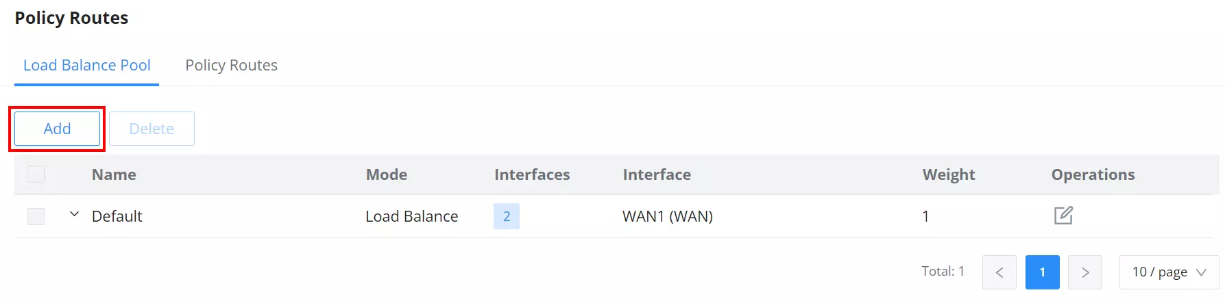
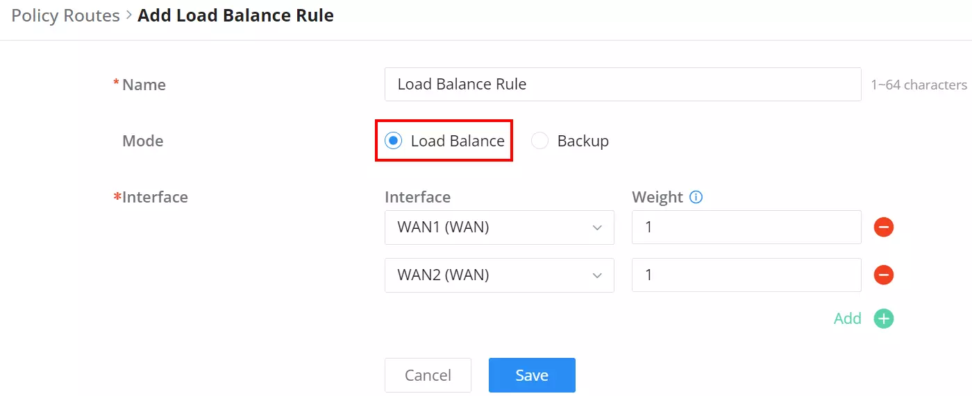
In this step, we will create a rule for the policy routing, which will enable load balancing. To create a load balance rule, navigate to Routing → Policy Routes page → Load Balance Pool tab, click onthe “Add” button, then select the mode (Load Balance), after that select the WAN ports from the drop-down list and specify the Weight for each port added. Please refer to the figures below:
Example 1: If you have WAN1 (100 Mbps) and WAN2 (50 Mbps), set weights as 2 and 1, respectively, to ensure balanced utilization proportional to bandwidth.

Example 2: If you have WAN1 (100 Mbps) and WAN2 (100 Mbps), set their weights to 1 and 1, respectively, to ensure balanced utilization proportional to their bandwidth. In this configuration, the bandwidth will be evenly distributed between the two connections.
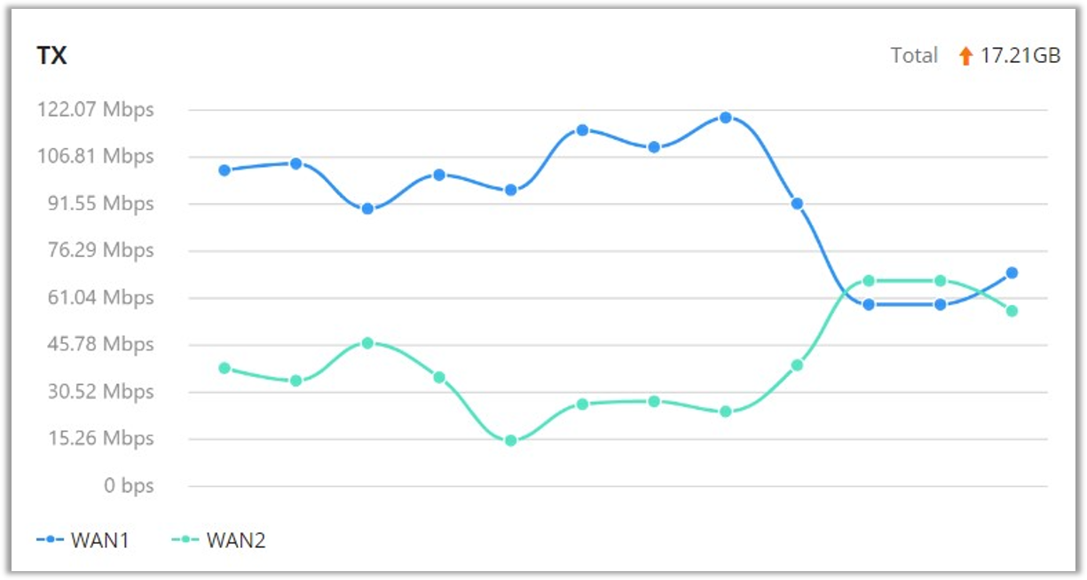
As shown below, both WANs will be active, and the utilization will depend on the weight of each WAN.
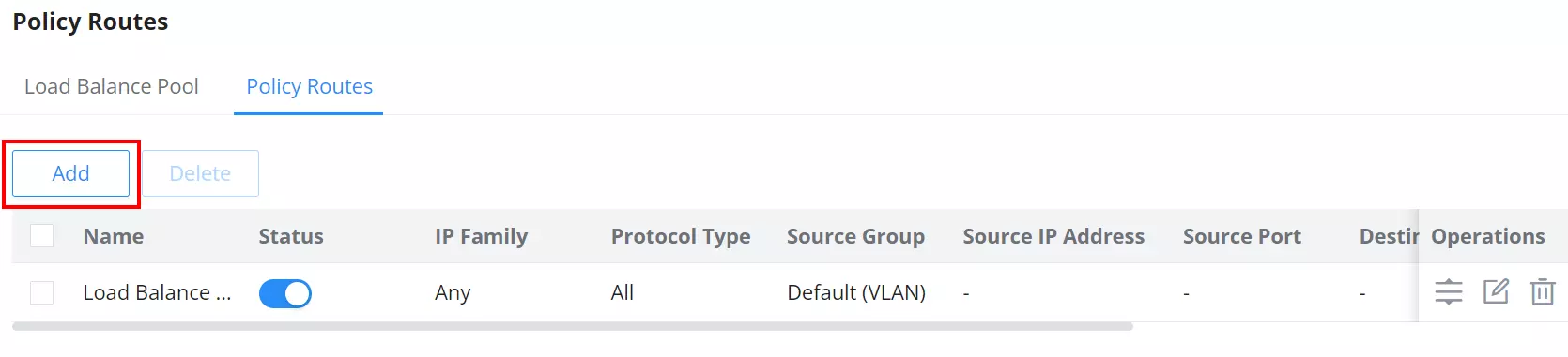
To create a Policy Route, please navigate to Routing → Policy Routes page → Policy Routes tab, then click on the “Add” button as shown below:
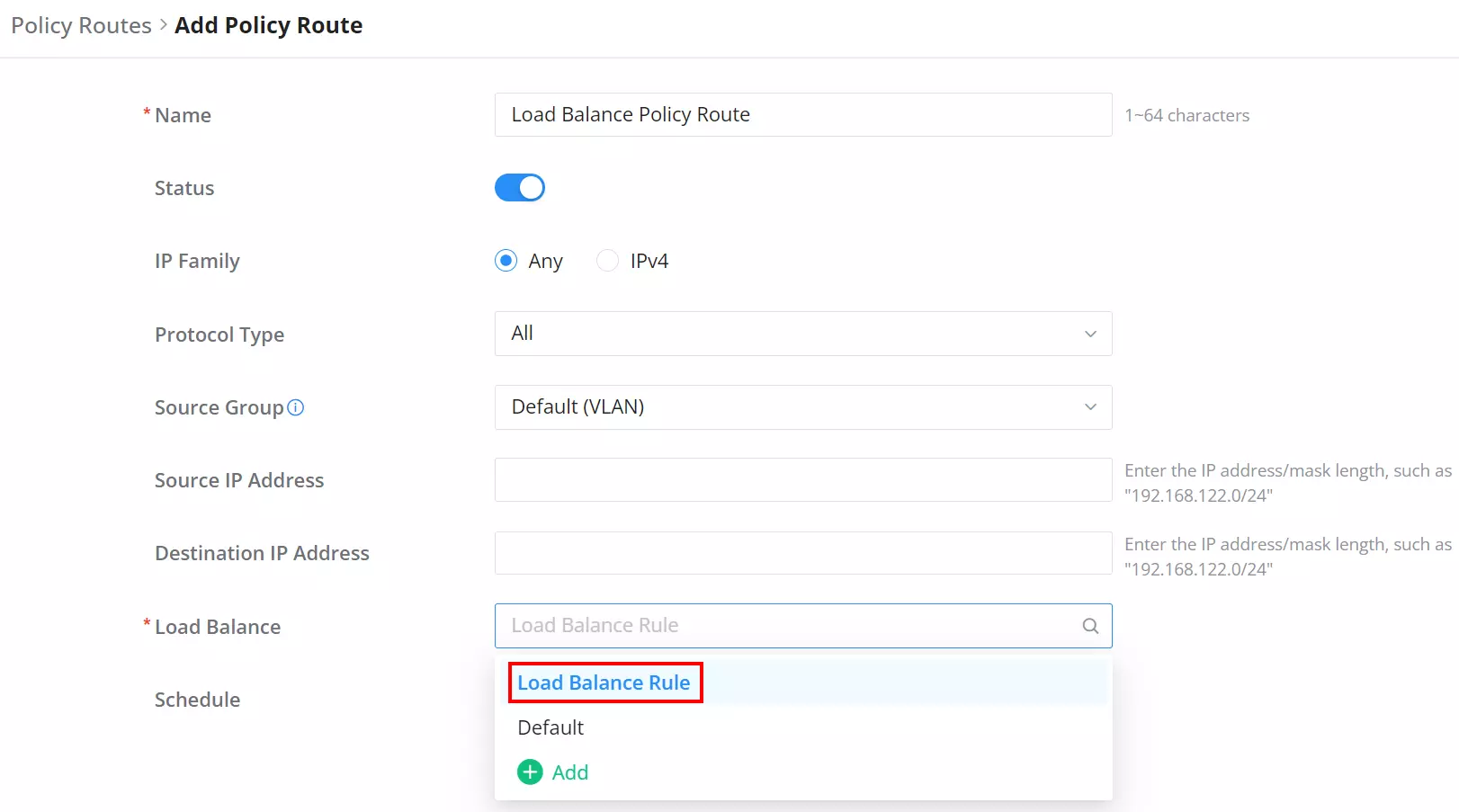
Then, under the Load Balance option, select the previously created load balance rule, and under Source Group, the user can select which network will use this policy route (in this case, it’s the default VLAN).
Backup Mode
- Purpose: Provide failover support by routing traffic to alternate interfaces when all preferred WAN interfaces fail.
- How It Works:
- In backup mode, the backup interfaces remain active and ready to handle traffic if a failure is detected on all preferred interfaces. However, the alternate interfaces only become active when all preferred interfaces are down. Once activated, traffic is distributed across the alternate interfaces based on their assigned weights.
- The status of the interfaces is monitored using ICMP replies to a tracking IP, which determines when the interface is up or down. For more details, refer to the WAN section. If the preferred interfaces come back online, traffic will revert to the primary interface after five consecutive tracking intervals (typically 60 seconds).
- Key Features:
- Backup interfaces are always active.
- Traffic can be distributed proportionally between preferred and backup interfaces if weights are configured.
To configure backup, we will follow the same steps above. However, we will set a different type of policy that ensures that one WAN port is used, while the other link will be a backup. Once one link goes down, the other link will automatically take over.
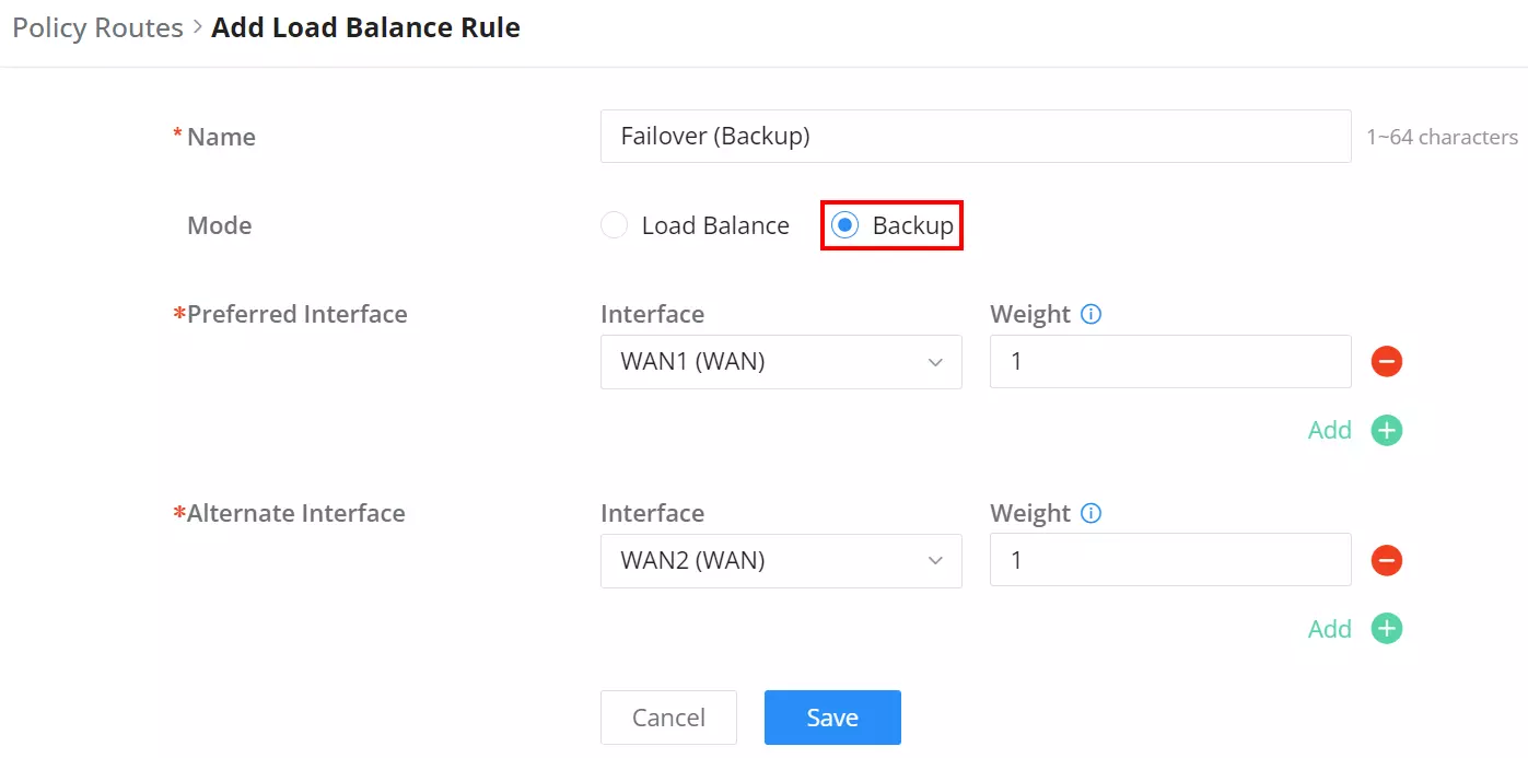
The users can click on the “+” icon to add an interface or the “–” icon to delete an interface.
Example 1: If both the preferred interfaces, WAN1 and VPN, are down, only then will the alternate interfaces, WAN2 and WAN4, become active, with traffic distributed according to their assigned weights.

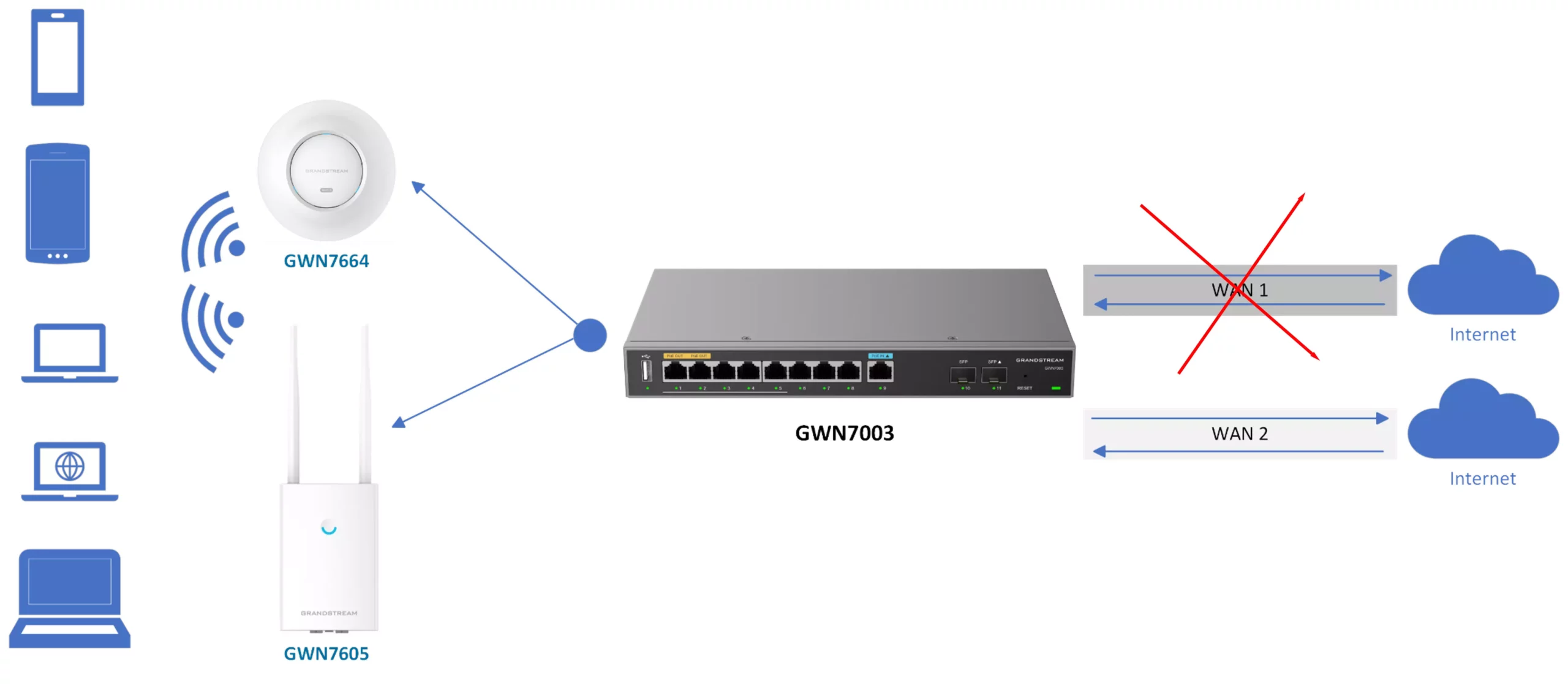
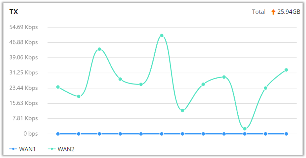
Example 2: In this Scenario when the WAN1 is down or disconnected the WAN 2 will be active and all the outgoing requests will be using WAN 2. Please refer to the example below:
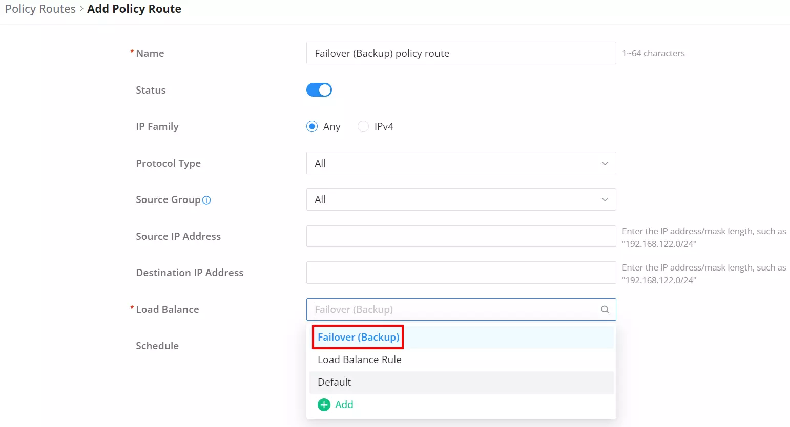
Under the Policy Routes tab, add a policy route and under Load Balance select the previously created Backup rule as shown below:
Standby Mode
- Purpose: maintain a single standby interface, which is only activated when all the primary interfaces fail. This is especially useful in cases like PPPoE authentication conflicts, where multiple active sessions can cause issues.
- How It Works:
- The standby interface remains inactive until all preferred (primary) interfaces fail. A Tracking IP Address (such as 1.1.1.1 or 8.8.8.8) is configured to monitor the status of the primary interface. The router pings this IP to check if the primary interface is up or down. If the pings fail continuously, the router switches to the standby interface.
- For PPPoE, authentication occurs only when the standby interface is activated, preventing simultaneous session conflicts.
- Failback occurs when the primary interface recovers, after five consecutive successful tracking intervals (typically 60 seconds), where the router pings a configured Tracking IP Address to check if the interface is back online. For PPPoE, failback may take up to 400 seconds due to session lock delays and the time required for PPPoE authentication to complete.
- Key Features:
- Standby interface remains inactive to conserve resources, activating only when needed.
- Resolves PPPoE authentication conflicts when the same account is configured across multiple WAN ports.
- Ensures smooth failback after the primary interface recovers, with an extended failback period for PPPoE sessions.
Example:
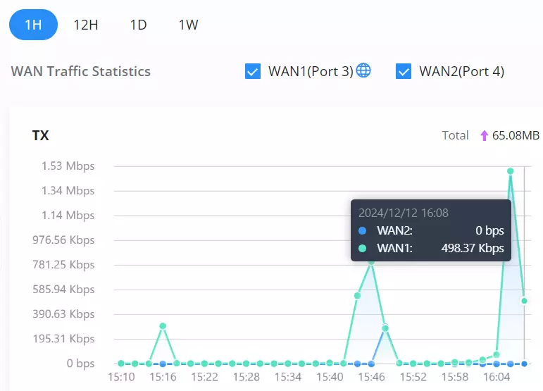
Use Standby Mode when two WAN ports require PPPoE with the same ISP credentials to prevent conflicts and maintain redundancy. For instance, WAN2 will store the PPPoE credentials but remain inactive. If WAN1, using the same credentials, fails or goes offline for any reason, WAN2 will automatically authenticate with the saved credentials and activate, ensuring seamless connectivity.

Since WAN2 is on Standby, it will not establish a connection until WAN1 goes down or fails to connect.

Comparison Table
| Feature/Mode | Load Balancing | Backup Mode | Standby Mode |
|---|---|---|---|
| Purpose | Distribute traffic across multiple interfaces. | Failover with active backup. | Failover with inactive standby. |
| Traffic Behavior | Balanced based on weights (Ratio). | When all preferred interfaces fail or become unavailable, the alternate interfaces will automatically take over. Traffic will be distributed proportionally between the alternate interfaces based on their configured weights, ensuring seamless failover | Activate the standby interface only when all preferred interfaces have failed. |
| Resource Usage | Utilizes all interfaces actively. | Backup interfaces are always active, and more than one interface can be configured as a backup. | The standby interface remains inactive, and only one interface can be designated as standby. |