


Overview
OSPF (Open Shortest Path First) is a dynamic routing protocol widely used in IP networks due to its efficiency in dynamically updating routes and adaptability to different network sizes. This guide explains the step-by-step configuration process for OSPF based on typical networking scenarios.
Supported Devices
The following device series support OSPF, providing robust and dynamic routing capabilities for modern network environments:
Device Type | Series |
Switches | GWN78xx Layer 3 Series |
Routers | GWN700x Series |
Convergence Solutions | GCC601x Series, GCC602x Series |
Supported Devices
For more information about these devices, visit Grandstream.
Networking Scenario
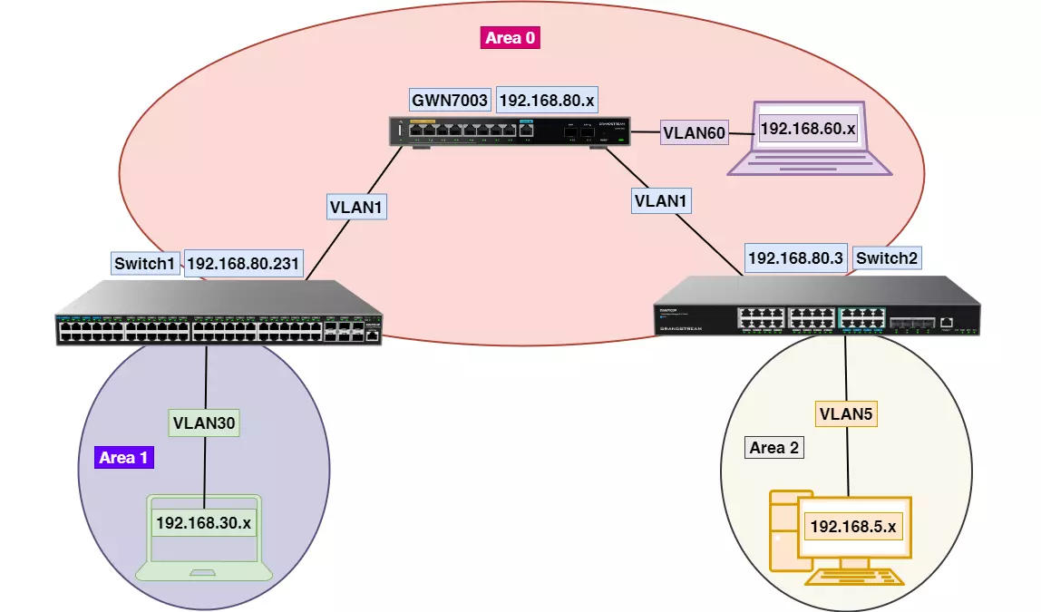
In a typical OSPF implementation, multiple devices, such as routers or switches, participate in exchanging routing information dynamically. This guide references the example network shown in the provided diagram, which includes:
- Area 0 (Backbone): Connecting GWN7003 to two switches and VLANs.
- Area 1: VLAN30 managed by Switch1.
- Area 2: VLAN5 managed by Switch2.
This setup demonstrates OSPF’s ability to reroute traffic in case of a link failure, ensuring efficient communication and failover support.
Global Settings
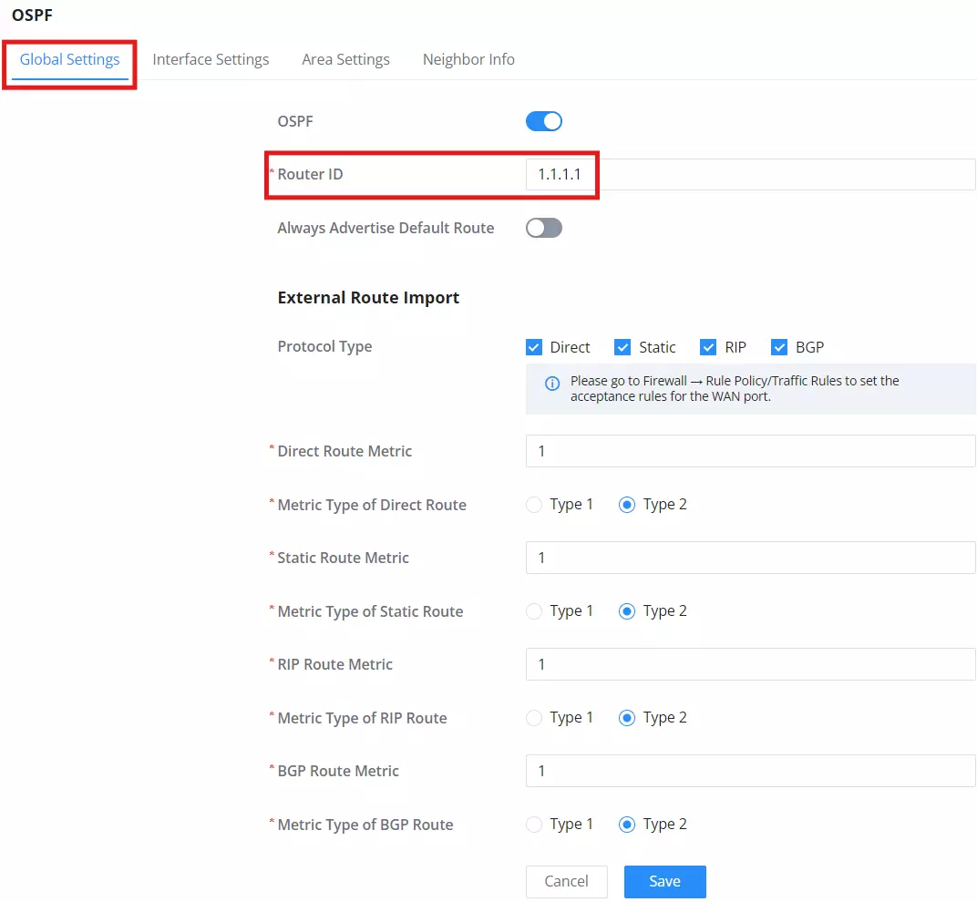
- Navigate to Routing → OSPF → Global Settings on the router or Routing → OSPF → Global on the switch.
- Enable OSPF using the toggle button.
- Assign a unique Router ID in IPv4 format (e.g., 1.1.1.1 for the router and 2.2.2.2 for the switch).
- Click Save to apply the configuration.
Interface Settings
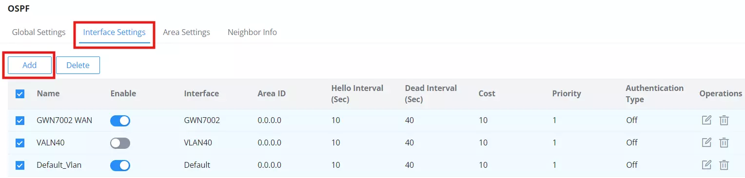
- Navigate to Routing → OSPF → Interface Settings on the router or switch.
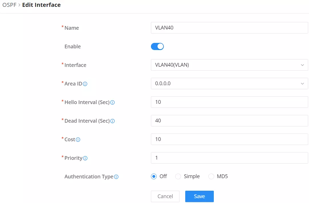
- Add or modify interfaces to enable OSPF on them.
- Configure parameters such as:
- Area ID: Assign the appropriate Area ID for each interface (e.g., 0.0.0.0 for Area 0).
- Interface Address: Verify the correct IP address assigned to the interface.
- Network Type: Choose the appropriate type (e.g., Broadcast).
- Cost: Assign a cost value (default is 10) to influence route selection.
- Authentication Type: Choose between Disabled, Simple, or MD5 authentication as needed.
- Save the settings by clicking Save.
- Notes:
- On switches, ensure VLAN interfaces (e.g., VLAN30, VLAN5) are configured with the correct Area ID and Network Type.
- For routers, include WAN or LAN connections in addition to VLANs if applicable.
- Use consistent Area IDs and interface configurations across all devices to ensure smooth OSPF operation.
- Example:
- Router: Enable OSPF for Default VLAN with Area ID 0.0.0.0.
- Switch: Enable OSPF for VLAN1 (e.g., 192.168.80.3/24) and VLAN5 (e.g., 192.168.5.1/24) with Area ID 0.0.0.0.
Area Settings
Areas in OSPF are logical groupings of networks that help organize and optimize the routing process. For example, in large networks, areas improve scalability by allowing routers to manage only the routes within their respective areas while abstracting external routes. This minimizes the size of routing tables and reduces the processing load on routers. In our example network, Area 0 serves as the backbone, interconnecting Areas 1 and 2, which handle their respective VLANs, ensuring localized routing and efficient communication. They are particularly beneficial in large networks where managing a single routing table could lead to inefficiency and high resource usage. By dividing the network into areas:
- Scalability is enhanced as routers focus on their own area’s routing table.
- Network Stability improves as changes in one area do not impact others.
- Optimized Resource Usage is achieved as OSPF reduces the amount of routing information exchanged.In our example topology:
- Area 0 (Backbone): Serves as the core of the network, interconnecting all other areas.
- Area 1: Contains VLAN30 on Switch1, ensuring localized routing within its devices.
- Area 2: Contains VLAN5 on Switch2, similarly handling its local routing. The backbone (Area 0) is mandatory and connects all other areas, ensuring communication across the network.
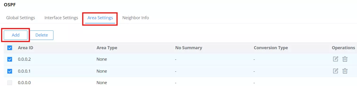
- Navigate to Routing → OSPF → Area Settings.
- Add or modify Area IDs to match your network design (e.g., 0.0.0.0 for Area 0, 0.0.0.1 for Area 1).
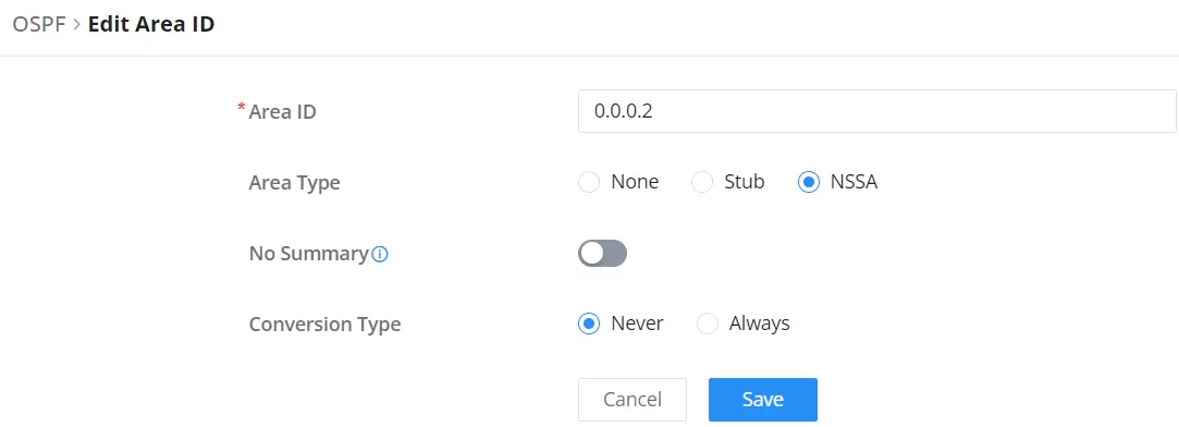
- Configure parameters such as:
- Area Type: Define the area type (e.g., Normal, Stub, or NSSA) depending on your network needs.
- No Summary: Enable or disable summarization for the area.
- Conversion Type: Set the conversion type (e.g., Never or Always).
- Save the settings by clicking Save.
- Notes:
- Ensure Area IDs for switches match the router’s configuration to maintain consistency and enable proper routing.
- Choose appropriate Area Types to optimize routing efficiency and meet specific network design goals.
- In the example network, Area IDs align with VLANs and their respective switches for clear segmentation and efficient routing.
Neighbor Information
- Navigate to Routing → OSPF → Neighbor Info on the router or switch.
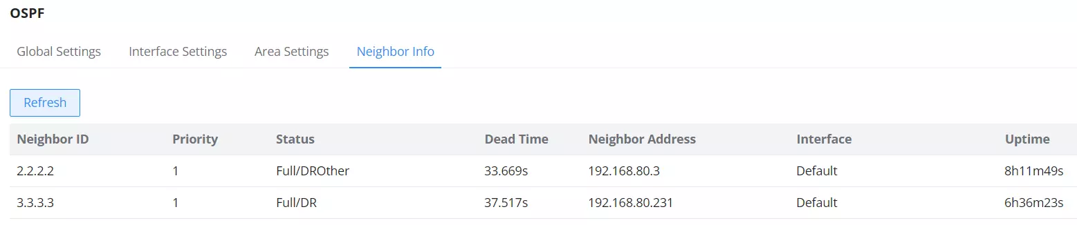
- View the list of learned OSPF neighbors in the Neighbor Table.
- Verify the following details for each neighbor:
- Neighbor ID: The Router ID of the neighboring router, essential for identifying and troubleshooting specific routers within the OSPF domain. This helps administrators pinpoint issues and monitor the health of OSPF adjacencies.
- Priority: The priority value used to determine the designated router (DR). This value plays a crucial role in OSPF by influencing the election process for the designated router (DR) and backup designated router (BDR). A higher priority increases the likelihood of a router becoming the DR, which is essential for network stability and efficient routing in broadcast and non-broadcast networks.
- Status: The current OSPF adjacency state (e.g., Full/DROther, Full/Backup). These states indicate the relationship between routers: ‘Full’ means the routers have successfully exchanged routing information, while states like ‘DROther’ or ‘Backup’ help define the roles of routers in the OSPF network. Understanding these states is critical for diagnosing adjacency or communication issues.
- Dead Time: The remaining time before the neighbor is declared down if no Hello packets are received. Adjusting the Dead Time can affect network reliability and convergence speed by determining how quickly a router reacts to a failed neighbor, balancing responsiveness and stability.
- Neighbor Address: The IP address of the neighbor.
- Uptime: The duration for which the neighbor relationship has been established. This metric helps monitor the stability of OSPF adjacencies by indicating how long a relationship has been consistently maintained, providing insights into potential network disruptions or flapping connections.
- Notes:
- The Neighbor Information section is similar for both the router and switches. Ensure neighbors are correctly listed with accurate states and addresses.
- This table helps verify the establishment and health of OSPF adjacencies across devices.
Verifying Route Learning
To ensure that OSPF is functioning correctly and routes are being learned, follow these steps:
1. Navigate to the Routing Table
- Go to Routing → Routing Table on the router or switch.
- Check for any anomalies, such as missing OSPF entries or incorrect next-hop addresses. Look for mismatched administrative distances, as these can indicate configuration or connectivity issues.
2. Review the Routing Table Entries
- Verify that routes learned via OSPF are listed under the “Protocol Type” column as “OSPF.”
- Confirm the next hop and administrative distance values for the OSPF-learned routes.
3. Example Routing Table Entries
The routing table screenshot below highlights OSPF-learned routes:
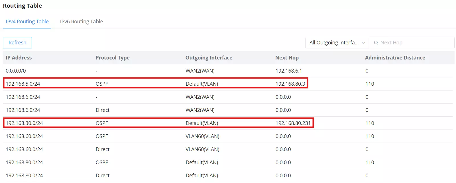
- 192.168.5.0/24:
- Protocol Type: OSPF
- Outgoing Interface: Default(VLAN)
- Next Hop: 192.168.80.3
- Administrative Distance: 110
- 192.168.30.0/24:
- Protocol Type: OSPF
- Outgoing Interface: Default(VLAN)
- Next Hop: 192.168.80.231
- Administrative Distance: 110
External Route Import (Supplementary Scenario)
External route import allows OSPF to integrate routes from outside its domain, such as directly connected subnets or other routing protocols. This is especially beneficial in scenarios like integrating legacy systems that rely on static routes or hybrid networks where different routing protocols coexist. By leveraging external route import, OSPF can ensure seamless connectivity across diverse network setups without requiring significant reconfiguration. This feature simplifies routing configurations by enabling OSPF to automatically include external routes in its advertisements without requiring dedicated interface settings for every subnet.
Advantages:
- Simplifies Configuration: Reduces manual effort for adding external subnets (e.g., VLAN40 in this scenario).
- Enhances Connectivity: Ensures seamless integration of external subnets into the OSPF network.
- Optimizes Resources: Eliminates the need to configure additional OSPF parameters for simple networks.
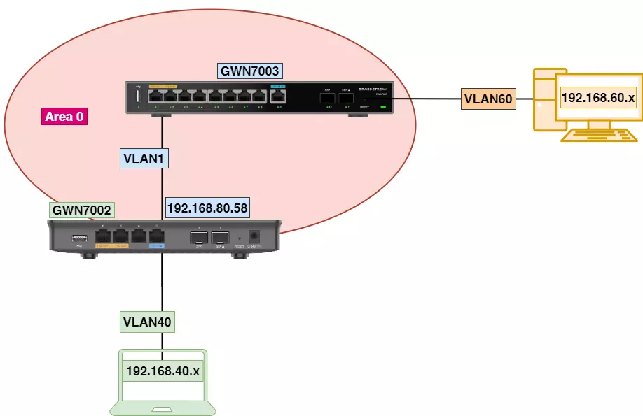
Example Topology:
- Router GWN7003 (Area 0): Configured with VLAN1 and VLAN60 as part of the OSPF domain.
- Router GWN7002 (Direct Routing Enabled): Advertises VLAN40 as an external route to GWN7003 without requiring dedicated OSPF interface configurations.
- Steps to Configure:
- On GWN7003, navigate to Routing → OSPF → Global Settings, and enable OSPF.
- Configure VLAN1 and VLAN60 under Routing → OSPF → Interface Settings with Area ID 0.0.0.0.
- On GWN7002, enable direct routing for VLAN40 by navigating to its interface settings and ensuring it is part of the connected subnets.
- Notes:
- Refer to the earlier sections of this guide for common configuration steps for OSPF, which include enabling OSPF, configuring Router IDs, setting up interface settings, and verifying neighbor information. Summarizing these steps ensures that readers can quickly review essential processes without navigating back through the guide.
- Ensure Router IDs are unique for GWN7003 and GWN7002 to avoid conflicts.
- Use the Neighbor Info table on both routers to verify connectivity and route propagation.
Configuring Firewall Rules
To allow OSPF to function correctly, appropriate firewall rules must be configured to permit WAN-to-LAN traffic based on VLANs:
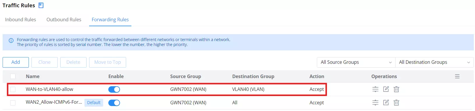
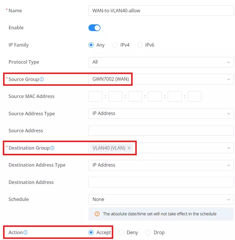
- Navigate to Firewall → Traffic Rules → Forwarding Rules.
- Add a new rule with the following settings:
- Name: Assign a descriptive name, e.g., wan-to-lan-accept.
- Source Group: Select the WAN interface of the router, e.g., GWN7002 (WAN).
- Destination Group: Select the VLAN created on the router, e.g., VLAN40 (VLAN) for GWN7002.
- Action: Set to
Acceptto allow traffic. - Protocol Type: Set to All or specify the necessary protocol.