
Overview
UCM6301/6302/6300A/6302A is an innovative IP PBX appliance designed for small to medium business. Powered by an advanced hardware platform with robust system resources, the UCM6301/6302/6300A/6302A offers a highly versatile state-of-the-art Unified Communication (UC) solution for converged voice, video, data, fax and video surveillance application needs. Incorporating industry-leading features and performance, the UCM6301/6302/6300A/6302A offers quick setup, easy deployment and unrivaled reliability all at an unprecedented price point.
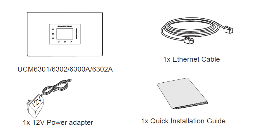
Package Contents
Hardware Installation
UCM6301/6302/6300A/6302A can be installed on the desktop or on the wall, and can be installed in a cabinet on a pallet.. Please refer to the following steps for correct installation.
Wall Installation
- Before formally installing the expansion screws, clarify the specific location of the expansion screws and make a mark.
- Pay attention to the following points when drilling: First, the drill bit model (aperture) used for drilling refers to the maximum diameter of the expansion tube equipped with the expansion screw; second, the drilling depth refers to the length of the expansion tube, slightly deeper than 5~10mm.
- After the expansion tube is inserted into the punched hole, it can be tapped lightly with a hammer to make the expansion tube and the wall flat.
- Fix the equipment well and fix the self-tapping screw in the expansion tube.
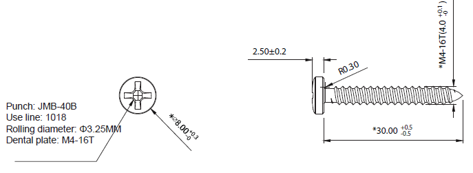
Self-tapping screw specifications
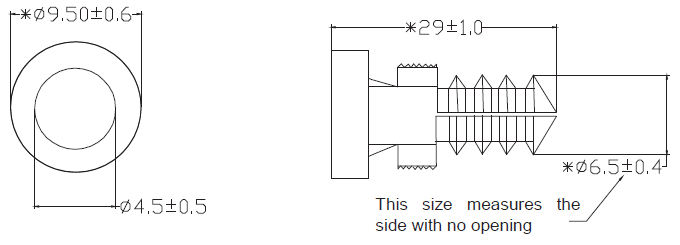
Expansion screw specifications
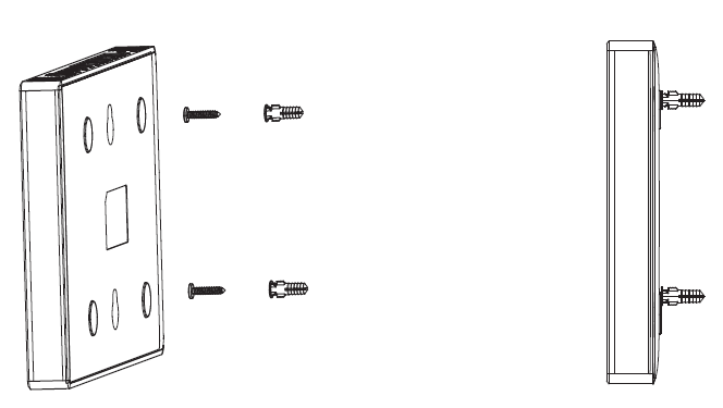
Schematic Diagram of Wall-Mounted Installation
Connecting the UCM6301/6302/6300A/6302A
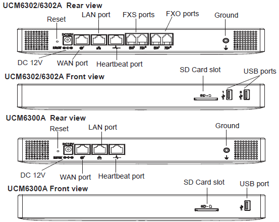
- Connect one end of an RJ-45 Ethernet cable into the WAN port of the UCM6301/6302/6300A/6302A.
- Connect the other end of the Ethernet cable into the uplink port of an Ethernet switch/hub.
- Connect the 12V DC power adapter into the 12V DC power jack on the back of the UCM6301/6302/6300A/6302A. Insert the main plug of the power adapter into a surge-protected power outlet.
- Wait for the UCM6301/6302/6300A/6302A to boot up. The front LCD display will show the UCM’s hardware information when the boot process is completed.
- Once the UCM6301/6302/6300A/6302A is successfully connected to network via WAN port, pressing the “Home“ button will allow you to get the IP address as well as other information.
- (Optional) Connect PSTN lines from the wall jack to the FXO ports, connect analog devices (phone and fax) to the FXS ports (UCM6301/6302/6302A only).
Using the UCM6301/6302/6300A/6302A LCD Menu
- Press “Settings“ key to start browsing menu options.
- Press “Navigation Key” to browse different menu options. Press “OK” to select an entry.
- In the menu option, select “Back” to go back to previous menu.
- The LCD will return to default display after being idle in menu for longer than
30 seconds.
Configuring the UCM6301/6302/6300A/6302A via web GUI
- Connect the computer to the same network as the UCM6301/6302/6300A/6302A.
- Ensure the UCM6301/6302/6300A/6302A is properly powered on then press the “Home“ button to displays the IP address and other information on the LCD screen.
- Open a web browser on the computer and enter the displayed IP address into the search bar in the following format: http(s)://ipaddress:portnumber
- Enter admin’s username and password to access the configuration menu. (The factory default username is “admin” while the default random password can be found on the sticker at the back of the unit).
- For more detailed information on how to configure SIP extensions, PSTN connections, SIP trunks, and other system settings via the web UI, please download the UCM6301/6302/6300A/6302A user manual here: http://www.grandstream.com/support/
Refer to online documents and FAQ for more detailed information:
http://www.grandstream.com/our-products

For Certification, Warranty and RMA information, please visit