
VLAN (Virtual Local Area Network) allows to separate network devices in logical groups despite of their physical location. Only members in same VLAN can communicate with each other. It also confines the broadcast domain to its members.
VLANs are implemented to achieve scalability, security and ease the network management and can quickly adapt to changes in network requirements and relocation of workstations and servers.
802.1Q is the standard that supports VLANs on an Ethernet network, its frames are distinguished from ordinary Ethernet frames by the insertion of a 4-byte VLAN tag (VLAN ID) into the Ethernet header.
VLANs are used to achieve the following:
- Increase performance: Grouping users into logical networks will increase performance by limiting broadcast traffic to users performing similar functions within workgroups. Additionally, less traffic will need to be routed, and the latency added to routers will be reduced.
- Improve manageability: VLANs make large networks more manageable by allowing centralized configuration of devices located in assorted locations.
- Increase security options: VLANs have the ability to provide additional security not available in a shared network environment. A switched network delivers packets only to the intended recipients and packets only to other members of the VLAN. This allows the network administrator to segment users requiring access to sensitive information into separate VLANs from the rest of the general users regardless of physical location.
ABOUT VLAN
General
VLAN tag allows to distinguish between different VLAN broadcast domains on a group of LAN switches.
The inserted field to the Ethernet frame is composed of four bytes (32 bits). The VLAN tag is a two-byte (16 bits) field inserted between the source MAC address and the Ethertype field in an Ethernet frame as shown on Figure 1. Another two-byte field, the Tag Protocol Identifier (TPI or TPID), precedes the VLAN tag field.
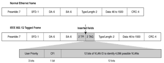
Two fields are necessary to hold one piece of information:
TPID (Tag Protocol Identifier): 2 Bytes after the source MAC address which will be set to a value of 0x8100 to denote that this frame carries 802.1Q or 802.1p tag information.
TCI (Tag Control Information): 2 Bytes which are made of the following:
- 3-bit user Priority Code Point (PCP) that sets a priority value between 0 and 7, which can be used for Quality of Service (QoS) priority traffic delivery, as shown on Table 1.
- 1-bit Canonical Format Indicator (CFI) that is a compatibility bit between Ethernet and other network structures, such as Token Ring. For Ethernet networks, this value will also be set to zero.
- 12-bit VLAN Identifier (VID) identifies the VLAN that the frame belongs to.
| PCP | Priority | Acronym | Traffic Types |
|---|---|---|---|
1 | 0 (lowest) | BK | Background |
0 | 1 | BE | Best Effort |
2 | 2 | EE | Excellent Effort |
3 | 3 | CA | Critical Applications |
4 | 4 | VI | Video, < 100ms latency and jitter |
5 | 5 | VO | Voice, < 10ms latency and jitter |
6 | 6 | IC | Internetwork Control |
7 | 7(highest) | NC | Network Control |
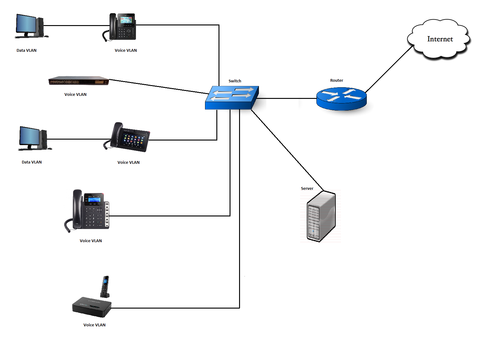
Voice VLAN
The Voice traffic is sensitive to delay and jitter, thus it requires a higher priority than data traffic to reduce the delay and packet loss during transmission, separating voice and data traffic using VLANs provides a solid security boundary, preventing data applications from reaching the voice traffic. It also gives user a simpler method to deploy QoS, prioritizing the voice traffic over the data. This feature enables access port of the switch to affect the connected device to a separated logical group, once this feature is enabled the ports set on the voice VLAN will allow simultaneous access for the PC, therefore the device and PC can be connected to one switch port through the device, LAN port will be connected to the Switch and PC port to the PC, after configuring VLAN tags for PC and LAN port the device will tag all packets from those port with VLAN ID, the switch will then forward the received packets to the corresponding VLAN ID.
VLAN CONFIGURATION
There are 3 ways to get VLAN ID on Grandstream products for the LAN port:
- Discovery using LLDP
- DHCP VLAN Option 132, 133
- Manual configuration
LLDP (Link Layer Discovery Protocol)
The Link Layer Discovery Protocol (LLDP) is a Layer 2 discovery protocol defined in the IEEE 802.1ab.
Nodes transmit information about themselves and listen for information about the devices on each connection, LLDP defines a standard SNMP MIB (Management Information Base) which can store information gathered locally and can be queried by SNMP to facilitate network management.
LLDP encapsulates all the device information in LLDPDUs (LLDP Data Units), which are then sent to neighboring nodes. A LLDPDU contains a variety of type length values (TLVs). In a TLV, “T” indicates the information type, “L” indicates the information length, and “V” indicates the value or the content to be sent.
Devices send/receive LLDPDUs with different TLVs to advertise their local information and receive neighbor information.
| TLV Type | TLV Name | Usage in LLDPDU | Description |
|---|---|---|---|
0 | End of LLDPDU | Mandatory | This marks the end of the TLV sequence in the LLDPDU. After this TLV, there is no further processing. This is a mandatory filed that need to be present at the end of the data stream. |
1 | Chassis ID | Mandatory | Contains the IP address of the sending port. |
2 | Port ID | Mandatory | Contains the MAC address of the device. |
3 | Time to Live | Mandatory | Specifies the life of the transmitted information on the device. |
4 | Port description | Optional | Describes the sending port. |
5 | System Name | Optional | Specifies the assigned name for the device. |
6 | System Description | Optional | Specifies the description of the device. |
7 | System Capabilities | Optional | Specifies the supported and enabled capabilities of the device, the supported and enabled capabilities by default are Bridge and Telephone. |
8 | Management Address | Optional | The type of management address used in LLDPDU |
9-126 | Reserved | – | – |
127 | Organizationally specific TLVs | Optional | LLDP specification allows for various organizations to define and encode their own TLVs. |
LLDP-MED
LLDP-MED is an extension of LLDP, that exchanges messages between Network devices such as switches and VoIP devices, it is published by the Telecommunications Industry Association (TIA). It provides the following capabilities for VoIP devices:
| LLDP-MED TLVs | Description |
|---|---|
LLDP-MED capabilities | Allows endpoints to determine the capabilities that the connected device supports and what capabilities the device has enabled. |
Network Policy | Allows both network connectivity devices and endpoints to advertise VLAN configurations and associated Layer 2 and Layer 3 attributes for the specific application on that port. For example, the switch can notify the device of the VLAN number that it should use. The device can connect into any switch, obtain its VLAN number, and then start communicating with the call control. |
Power Management | Enables advanced power management between LLDP-MED endpoint and network connectivity devices. Allows switches and devices to convey power information, such as how the device is powered, power priority, and how much power the device needs. |
Inventory Management | Allows an endpoint to transmit detailed inventory information about itself to the switch, including information hardware revision, firmware version, software version, serial number, manufacturer name, model name, and asset ID TLV. |
Location | Provides location information from the switch to the endpoint device. The location TLV can send this information:
|
In order to enable/disable LLDP option from the Web GUI, please refer to following table showing the location of LLDP option.
| Device | Location in the Web GUI |
|---|---|
GXP21xx Color | Network 🡪 Advanced Settings |
GXP17xx | Network 🡪 Advanced Settings |
GXP16xx | Network 🡪 Advanced Settings |
GXV32xx | Maintenance 🡪 Network Settings |
GXW42xx | Maintenance 🡪 Network Settings |
DP750 | Settings 🡪 Network Settings 🡪 Advanced Settings |
GAC2500 | Maintenance 🡪 Network Settings |
GVC32xx | Settings > Network Settings |
Configuring LLDP via Configuration File
For GXP21xx color, GXP17xx, GXP16xx, GXV32xx, DP750, GXW42xx, GVC32xx and GAC2500 series, administrator can edit following P-values:
- P1684=0 to disable the LLDP feature.
- P1684=1 to enable the LLDP feature.
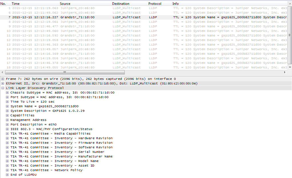
LLDP Flow (Wireshark)
Since the LLDP feature is activated by default, the SIP client will behave as follows:
- Send LLDP advertisement each 30 second.
- Send/receive LLDP packets from LAN port.
- Support the MAC/PHY Configuration/Status.
- Obtain VLAN information (ID, L2 Priority, DSCP Priority…) from the Network policy.
The following trace shows the packets advertised and received by the GXP1625.
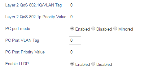
Manual Configuration
For manual configuration user can make the settings either via configuration file or via Web GUI.
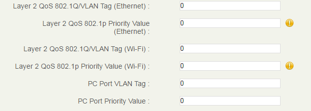
Configuring VLAN Manually via Web GUI
| Device | Location in the Web GUI |
|---|---|
GXP21xx | Network 🡪 Advanced Settings |
GXP17xx | Network 🡪 Advanced Settings |
GXP16xx | Network 🡪 Advanced Settings |
GXV32xx | Maintenance 🡪 Network Settings |
GXW42xx | Maintenance 🡪 Network Settings |
DP750 | Settings 🡪 Network Settings 🡪 Advanced Settings |
HT8xx/HT7xx/HT5xx | Advanced Settings |
GVC32xx | Settings 🡪 Network Settings |
GAC2500 | Maintenance 🡪 Network Settings |
Configuring VLAN Manually via Configuration File
| Device | Field | P-value |
|---|---|---|
GXP21xx |
| P51 |
| P87 | |
| P229 | |
| P230 | |
GXP17xx |
| P51 |
| P87 | |
| P229 | |
| P230 | |
GXP16xx |
| P51 |
| P87 | |
| P229 | |
| P230 | |
GXV32xx |
| P51 |
| P87 | |
| P22047 | |
| P22048 | |
| P229 | |
| P230 | |
GXW42xx |
| P51 |
| P5038 | |
| P5042 | |
DP750 |
| P51 |
| P5038 | |
| P5042 | |
| P27004 | |
HT8xx/HT7xx/HT5xx |
| P51 |
| P5038 | |
| P5042 | |
GVC32xx |
| P51 |
| P87 | |
GAC2500 |
| P51 |
| P87 | |
| P22047 | |
| P22048 |
Screenshots Examples for LLDP and Manual Configuration Settings
GXP21xx, GXP17xx & GXP16xx Series
| GXV32xx Series Maintenance 🡪 Network Settings 
|
GXW42xx Series Maintenance > Network Settings 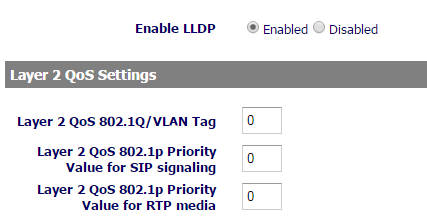
| DP750 Settings > Network Settings > Advanced Settings 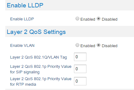
|
HT8xx/HT7xx/HT5xx Series Advanced Settings 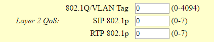
| GVC32xx Series Settings > Network Settings 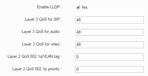
|
 Network 🡪 Advanced Settings
Automatic Configuration using DHCP VLAN options (GXV32xx only)
To use this feature, DHCP server needs to support Option 132 (VLAN option).
Following steps show how to install and configure a DHCP server supporting option 132.
In this guide, we will use isc dhcp server on Ubuntu 12.
- In order to install the server, open a terminal login as root and type the following command:

- Once the server is downloaded and installed successfully, we need to set the PC interface which will listen and advertise DHCP packets. This can be done by editing:

- Once the above command is typed, the following window will be shown:
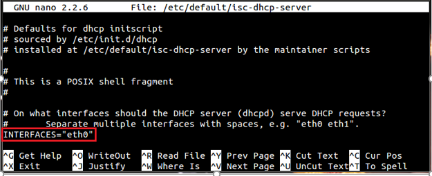
- Replace eth0 on the above screenshot with the name of user network interface the server will lease addresses on, then save and exit the file using “Ctrl+X”
- Now we need to edit the dhcp configuration file to set our option:

- Once the above command is typed the configuration file will be prompted, add following lines to activate DHCP option 132.

- This will affect the device to vlan20.
- Administrator can save changes made on that file by typing “Ctrl+X” then confirm with “Y”
- Restart DHCP services with the following command:

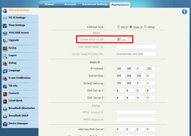
Configuring DHCP VLAN option on GXV32xx via Web GUI
To activate option 132 on the GXV32XX series, administrator can activate it from the Web GUI.
- Log in to the Web GUI.
- Go under “Maintenance > Network Settings”.
- Click on the checkbox “Enable DHCP VLAN”, this will allow the device to retrieve the VLAN ID and priority from the DHCP server (Option 132, Option 133).
- Click on “Save” to save the changes.
Configuring the DHCP VLAN option on the GXV32xx via configuration file
For the GXV32xx series user can edit P-value:
P8300=0 to disable the DHCP VLAN option.
P8300=1 to enable the DHCP VLAN option.
DHCP VLAN Option Wireshark Flow
Once the DHCP VLAN option activated the device will behave as follow:
- Send DHCP Discover that include Option 132 requesting for a VLAN Tag.
- Complete the Process of DHCP, (Discover, Offer, Request, ACK), the Offer and ACK will include the Tag value set on the DHCP server (VLAN ID = 20).
- The device will send another DHCP Discover this time including the VLAN Tag 20 in order to take an IP within this range.
- After the DCHP Process finish, the device will grab an IP address from the VLAN range.
The following trace show the packets advertised and received by the GXV3240.
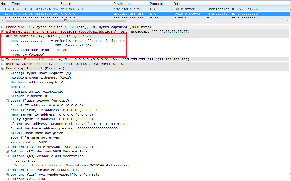
Figure 12: DHCP Discovery on GXV3240
SUPPORTED DEVICES
Following table shows Grandstream products supporting VLAN protocol.
| Model | VLAN Support | LLDP Support | Firmware |
|---|---|---|---|
GXP21xx | Yes | Yes | 1.0.7.25 or higher |
GXP17xx | Yes | Yes | 1.0.0.37 or higher |
GXP16xx | Yes | Yes | 1.0.4.6 or higher |
GVC3380 | Yes | Yes | 1.0.1.14 or higher |
GXV3350 | Yes | Yes | 1.0.1.8 or higher |
GXV3370 | Yes | Yes | 1.0.1.28 or higher |
GVC3200/3202 | Yes | Yes | 1.0.1.74 or higher |
GVC3210 | Yes | Yes | 1.0.1.69 or higher |
GVC3220 | Yes | Yes | 1.0.1.24 or higher |
GVC3212 | Yes | Yes | 1.0.0.6 or higher |
GAC2500 | Yes | Yes | 1.0.1.44 or higher |
GXW42xx | Yes | Yes | 1.0.5.16 or higher |
HT8xx | Yes | No | 1.0.2.5 or higher |
DP750/752 | Yes | Yes | 1.0.1.20 or higher |