INTRODUCTION
This document explains all the IPPBX features offered by Grandstream GCC601X(W) All-in-One devices. This document does not include the management features or settings related to the device overall or the other modules of the device.
Grandstream offers expansion package and add-ons for the IPPBX module in the GCC6000 Series. For more details, please refer to the following link: https://ucmrc.gdms.cloud/pbx/plans
SYSTEM STATUS
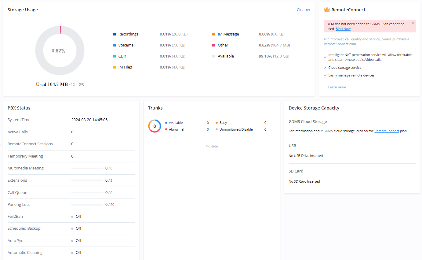
Dashboard
- Storage Usage
- RemoteConnect
- PBX Status
- Trunks
System Information
In this categor, the user can view all the information regarding the GCC device hardware and software. In addition to the networking information which is assigned to the device when connected to the network.
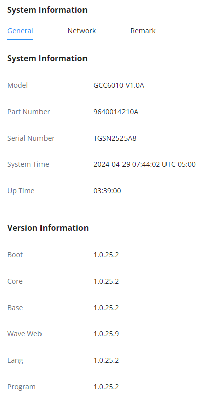
General
In this page, the user can see the hardware and software information about the the GCC device. This page includes information about the model of the device, the hardware version, the part number, the serial number, the system time, and the duration of the operation of the device. In addition to the version numbers of the different modules of the device’s software.
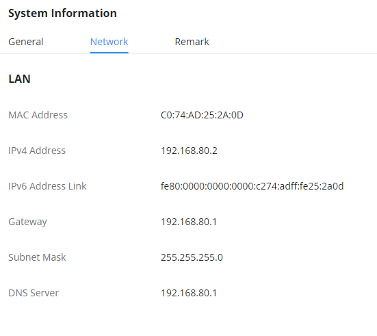
Network Settings
This page displays the network configuration and information of the device. The information displayed include the MAC address, IPv4 address, IPv6 address, the gateway, the subnet mask, and the preferred DNS server.
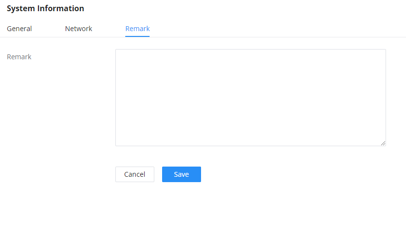
Remark
In this page, the user can enter specific information about the device to help easy identification.
Active Calls
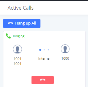
The active calls on the IPPBX are displayed in the Web GUI🡪System Status🡪Active Calls page. Users can monitor the status, hang up a call, and barge in the active calls in a real-time manner.
Active Calls Status
To view the status of active calls, navigate to Web GUI🡪System Status🡪Active Calls. The following figure shows extension 1004 is calling 1000. 1000 is ringing.
The following figure shows the call between 1000 and 5555 is established.
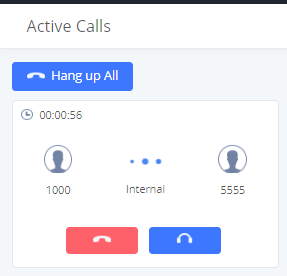
The gray color of the active call means the connection of call time is less than half an hour. It means this call is normal.
The orange color of the active call means the connection of call time is greater than half an hour but less than one hour. It means this call is a bit long.
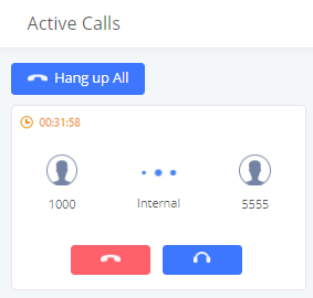
The red color of the active call means the connection of call time is more than one hour. It means this call could be abnormal.

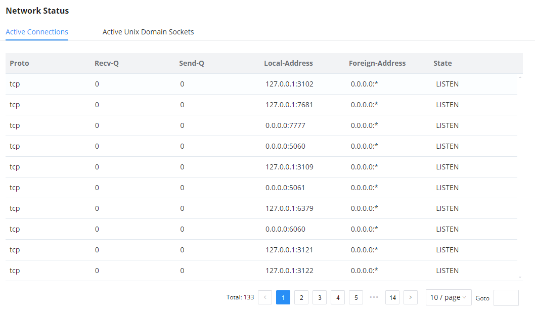
Network Status
This section shows the overall network status of the IPPBX module like the network services which are running on the IPPBX and the active unix domain sockets.
Active Connections
This page shows all the active connections of the IPPBX module with internal modules or devices using TCP/IP.
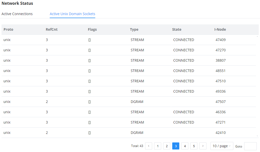
Active Unix Domain Sockets
This page shows the processes which are open and communcating with each other.
EXTENSION/TRUNK
This section combines settings related to extensions, trunks, and inbound/outbound routes.
Extensions
In this page the user can create, view, and configure all the extensions that exist on the PBX.
SIP Extension
To manually create a new SIP user, go to Web GUI🡪Extension/Trunk🡪Extensions. Click on “Add” and a new window will show for users to fill in the extension information.
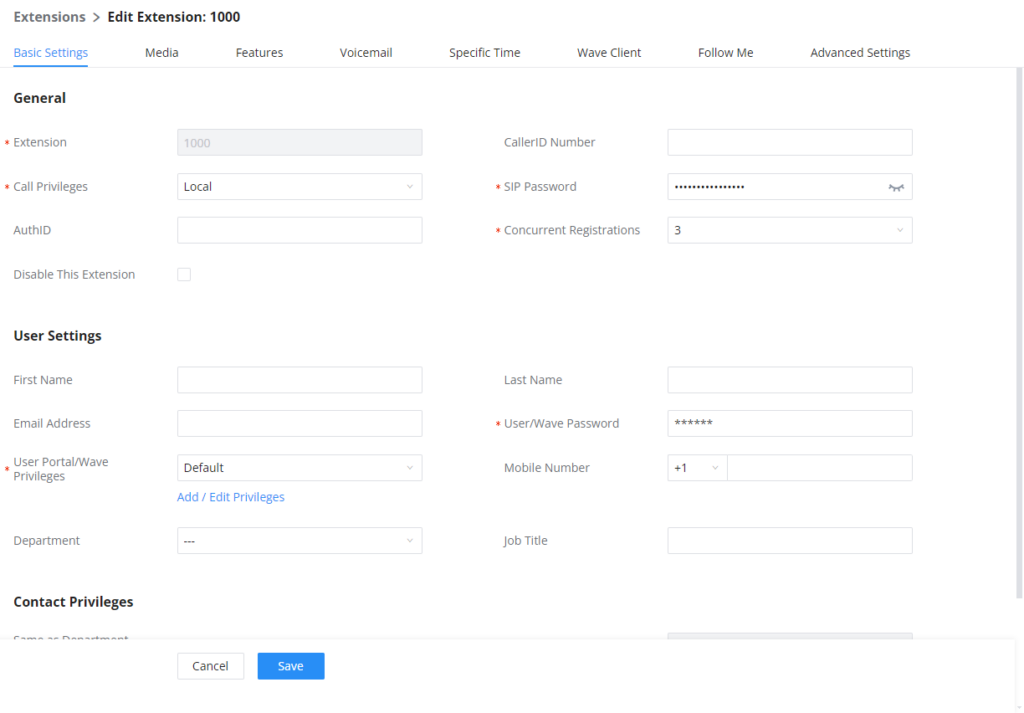
Extension options are divided into five categories:
- Basic Settings
- Media
- Features
- Specific Time
- Wave
- Follow me
- Advanced Settings
The configuration parameters are as follows.
General | |
Extension | The extension number associated with the user. |
CallerID Number | Configure the CallerID Number that would be applied for outbound calls from this user. Note: The ability to manipulate your outbound Caller ID may be limited by your VoIP provider. |
Call Privileges | Assign permission level to the user. The available permissions are "Internal", "Local", "National" and "International" from the lowest level to the highest level. The default setting is "Internal". Note: Users need to have the same level as or higher level than an outbound rule's privilege to make outbound calls using this rule. |
SIP/IAX Password | Configure the password for the user. A random secure password will be automatically generated. It is recommended to use this password for security purposes. |
Auth ID | Configure the authentication ID for the user. If not configured, the extension number will be used for authentication. |
Voicemail | Configure Voicemail. There are three valid options, and the default option is "Enable Local Voicemail".
|
Voicemail Password | Configure voicemail password (digits only) for the user to access the voicemail box. A random numeric password is automatically generated. It is recommended to use the randomly generated password for security purposes. |
Skip Voicemail Password Verification | When a user dials voicemail code, the password verification IVR is skipped. If enabled, this would allow one-button voicemail access. By default, this option is disabled. |
Send Voicemail Email Notification | Configures whether to send emails to the extension's email address to notify of a new voicemail. |
Attach Voicemail to Email | Configures whether to attach a voicemail audio file to the voicemail notification emails. Note: When set to “Default”, the global settings in Call Features 🡪 Voicemail 🡪 Voicemail Email Settings will be used. |
Keep Voicemail after Emailing | Whether to keep the local voicemail recording after sending them. If set to “Default”, the global settings will be used. Note: When set to “Default”, the global settings in Call Features 🡪 Voicemail 🡪 Voicemail Email Settings will be used. |
Enable Keep-alive | If enabled, an empty SDP packet will be sent to the SIP server periodically to keep the NAT port open. The default setting is "No". |
Keep-alive Frequency | Configure the Keep-alive interval (in seconds) to check if the host is up. The default setting is 60 seconds. |
Enable SCA | If enabled, (1) Call Forward, Call Waiting, and Do Not Disturb settings will not work, (2) Concurrent Registrations can be set only to 1, and (3) Private numbers can be added in Call Features🡪SCA page. |
Emergency CID Name | CallerID name that will be used for emergency calls and callbacks. |
Disable This Extension | If selected, this extension will be disabled on the UCM630X. Note: The disabled extension still exists on the PBX but cannot be used on the end device. |
Sync Contact | If enabled, this extension number will be displayed in the Wave contact, otherwise, it will not be displayed, and it cannot be found in the chat, but the user can still dial this number. |
User Settings | |
First Name | Configure the first name of the user. The first name can contain characters, letters, digits, and _. |
Last Name | Configure the last name of the user. The last name can contain characters, letters, digits, and _. |
Email Address | Fill in the Email address for the user. Voicemail will be sent to this Email address. |
User Password | Configure the password for user portal access. A random numeric password is automatically generated. It is recommended to use the randomly generated password for security purposes. |
Language | Select the voice prompt language to be used for this extension. The default setting is "Default" which is the selected voice prompt language under Web GUI🡪PBX Settings🡪Voice Prompt🡪Language Settings. The dropdown list shows all the currently available voice prompt languages on the UCM630X. To add more languages to the list, please download the voice prompt package by selecting "Check Prompt List" under Web GUI🡪PBX Settings🡪Voice Prompt🡪Language Settings. |
Concurrent Registrations | The maximum endpoints which can be registered into this extension. For security concerns, the default value is 3. Note: |
Mobile Phone Number | Configure the phone number for the extension, user can type the related star code for the phone number followed by the extension number to directly call this number. For example, the user can type * |
Department | Configure the user's department. The department can be configured in User Management->Address Book Management->Department Management. |
Contact Privileges | |
Same as Department Contact Privileges | When enabled, The extension will inherit the same privilege attributed to the department it belongs to. |
Contact View Privileges | Select the privileges regarding the contact view in SIP endpoints and Wave. |
SIP Extension Configuration Parameters > Basic Settings
SIP Settings | |
NAT | Use NAT when the UCM630X is on a public IP communicating with devices hidden behind NAT (e.g., broadband router). If there is a one-way audio issue, usually it is related to NAT configuration or the Firewall's support of SIP and RTP ports. The default setting is enabled. |
Enable Direct Media | By default, the UCM630X will route the media steams from SIP endpoints through itself. If enabled, the PBX will attempt to negotiate with the endpoints to route the media stream directly. It is not always possible for the UCM630X to negotiate endpoint-to-endpoint media routing. The default setting is "No". |
DTMF Mode | Select DTMF mode for the user to send DTMF. The default setting is "RFC4733". If "Info" is selected, the SIP INFO message will be used. If "Inband" is selected, a-law or u-law are required. When "Auto" is selected, RFC4733 will be used if offered, otherwise "Inband" will be used. |
TEL URI | If the phone has an assigned PSTN telephone number, this field should be set to “User=Phone”. The “User=Phone” parameter will be attached to the Request-Line and “TO” header in the SIP request to indicate the E.164 number. If set to “Enable”, “Tel” will be used instead of “SIP” in the SIP request. |
Alert-Info | When present in an INVITE request, the alert-Info header field specifies an alternative ring tone to the UAS. |
Enable T.38 UDPTL | Enable or disable T.38 UDPTL support. |
TURN Relay | Enable this option if the following are true:
Once a TURN server is configured, media will be forwarded to it. This configuration does not affect endpoints that are registered via the UCM's RemoteConnect address. |
SRTP | Enable SRTP for the call. The default setting is disabled. |
Jitter Buffer | Select the jitter buffer method.
|
Packet Loss Retransmission | Configure to enable Packet Loss Retransmission.
|
Video FEC | Check to enable Forward Error Correction (FEC) for Video. |
Audio FEC | Check to enable Forward Error Correction (FEC) for Audio. |
Silence Suppression | If enabled, the UCM will send CN packets for silence suppression after a successful CN negotiation in the SIP SDP. If the client endpoint's OPUS codec supports the reception of DTX packets, the UCM will send DTX packets instead. |
FECC | Configure to enable Remote Camera Management. |
ACL Policy | Access Control List manages the IP addresses that can register to this extension.
|
SRTP Crypto Suite | The following encryption protocols can be used to encrypt an RTP stream.
|
Codec Preference | Select audio and video codec for the extension. The available codecs are: PCMU, PCMA, GSM, AAL2-G. |
SIP Extension Configuration Parameters > Media
Call Transfer | |
Presence Status | Select which presence status to set for the extension and configure call forward conditions for each status. Six possible options are possible: “Available”, “Away”, “Chat”, “Custom”, “DND” and “Unavailable”. More details at [PRESENCE]. |
Internal Calls & External Calls | |
Call Forward Unconditional | Enable and configure the Call Forward Unconditional target number. Available options for target number are:
The default setting is “None”. |
CFU Time Condition | Select time condition for Call Forward Unconditional. CFU takes effect only during the selected time condition. The available time conditions are ‘All’, ‘Office Time’, ‘Out of Office Time’, ‘Holiday’, ‘Out of Holiday’, ‘Out of Office Time or Holiday’, ‘Office Time and Out of Holiday’, ‘Specific Time’, ‘Out of Specific Time’, ‘Out of Specific Time or Holiday’, ‘Specific Time and Out of Holiday’. Notes:
|
Call Forward No Answer | Configure the Call Forward No Answer target number. Available options for target number are:
The default setting is “None”. |
CFN Time Condition | Select time condition for Call Forward No Answer. The available time conditions are ‘All’, ‘Office Time’, ‘Out of Office Time’, ‘Holiday’, ‘Out of Holiday’, ‘Out of Office Time or Holiday’, ‘Office Time and Out of Holiday’, ‘Specific Time’, ‘Out of Specific Time’, ‘Out of Specific Time or Holiday’, ‘Specific Time and Out of Holiday’. Notes:
|
Call Forward Busy | Configure the Call Forward Busy target number. Available options for target number are:
The default setting is “None”. |
CFB Time Condition | Select time condition for Call Forward Busy. The available time conditions ‘All’, ‘Office Time’, ‘Out of Office Time’, ‘Holiday’, ‘Out of Holiday’, ‘Out of Office Time or Holiday’, ‘Office Time and Out of Holiday’, ‘Specific Time’, ‘Out of Specific Time’, ‘Out of Specific Time or Holiday’, ‘Specific Time and Out of Holiday’. Notes:
|
Do Not Disturb | If Do Not Disturb is enabled, all incoming calls will be dropped. All call forward settings will be ignored. |
DND Time Condition | Select time condition for Do Not Disturb. The available time conditions are “Office Time”, “Out of Office Time”, “Holiday”, “Out of Holiday”, “Out of Office Time or Holiday”, and “Specific”. Notes:
Office Time and Holiday could be configured on page System Settings🡪Time Settings🡪Office Time/Holiday page. |
DND Whitelist | If DND is enabled, calls from the whitelisted numbers will not be rejected. Multiple numbers are supported and must be separated by new lines. Pattern matching is supported.
|
FWD Whitelist | Calls from users in the forward whitelist will not be forwarded. Pattern matching is supported.
|
CC Settings | |
Enable CC | If enabled, UCM630X will automatically alert this extension when a called party is available, given that a previous call to that party failed for some reason. By default, it is disabled. |
CC Mode | Two modes for Call Completion are supported:
The default setting is “Normal”. |
CC Max Agents | Configure the maximum number of CCSS agents which may be allocated for this channel. In other words, this number serves as the maximum number of CC requests this channel can make. The minimum value is 1. |
CC Max Monitors | Configure the maximum number of monitor structures that may be created for this device. In other words, this number tells how many callers may request CC services for a specific device at one time. The minimum value is 1. |
Ring Simultaneously | |
Ring Simultaneously | Enable this option to have an external number ring simultaneously along with the extension. If a register trunk is used for outbound, the register number will be used to be displayed for the external number as the caller ID number. |
External Number | Set the external number to ring simultaneously. ‘-’ is the connection character that will be ignored. This field accepts only letters, numbers, and special characters + = * #. |
Time Condition for Ring Simultaneously | Ring the external number simultaneously along with the extension based on this time condition. |
Use callee DOD on FWD or RS | Use the DOD number when calls are being diverted/forwarded to external destinations or when ring simultaneous is configured. |
Monitor privilege control | |
Call Montoring Whitelist | Add members from “Available Extensions” to “Selected Extensions” so that the selected extensions can spy on the used extension using feature code. |
Allow Operator Panel Monitoring | Configure whether this extension can be monitored by the Operator Panel administrator. |
Seamless transfer privilege control | |
Allowed to seamless transfer | Any extensions on the UCM can perform a seamless transfer. When using the Pickup Incall feature, only extensions available on the “Selected Extensions” list can perform a seamless transfer to the edited extension. |
PMS Remote Wakeup Whitelist | |
Select the extensions that can set wakeup service for other extensions | Selected extensions can set a PMS wakeup service for this extension via feature code. |
Other Settings | |
Ring Timeout | Configure the number of seconds to ring the user before the call is forwarded to voicemail (voicemail is enabled) or hang up (voicemail is disabled). If not specified, the default ring timeout is 60 seconds on the UCM630X. The valid range is between 5 seconds and 600 seconds. Note: If the end point also has a ring timeout configured, the actual ring timeout used is the shortest time set by either device. |
Auto Record | Enable automatic recording for the calls using this extension. The default setting is disabled. The recordings can be accessed under Web GUI🡪CDR🡪Recording Files. |
Skip Trunk Auth |
|
Time Condition for Skip Trunk Auth | If ‘Skip Trunk Auth’ is set to ‘By Time’, select a time condition during which users can skip entering the password when making outbound calls. |
Dial Trunk Password | Configure personal password when making outbound calls via the trunk. |
Support Hot-Desking Mode | Check to enable Hot-Desking Mode on the extension. Hot-Desking allows using the same endpoint device and logs in using extension/password combination. This feature is used in scenarios where different users need to use the same endpoint device during a different time of the day for instance. If enabled, SIP Password will accept only alphabet characters and digits. Auth ID will be changed to the same as Extension. |
Enable LDAP | If enabled, the extension will be added to the LDAP Phonebook PBX list. |
Use MOH as IVR ringback tone | If enabled, when the call to the extension is made through the IVR, the caller will hear MOH as a ringback tone instead of the regular ringback tone. |
Music On Hold | Specify which Music On Hold class to suggest to the bridged channel when putting them on hold. |
Call Duration Limit | Check to enable and set the call limit the duration. |
Maximum Call Duration (s) | The maximum call duration (in seconds). The default value 0 means no limit. Max value is |
The Maximum Number of Call Lines | The maximum number of simultaneous calls that the extension can have. |
Outgoing Call Frequency Limit | If enabled, if the number of outbound calls exceed the configured threshold within the specified period, further outbound calls will be not be allowed. |
Send PCPID Header | If enabled, this extension's SIP INVITE messages will contain the P-Called-Party-ID (PCPID) header if the callee is a SIP device. |
Period (m) | The period of outgoing call frequency limit. The valid range is from 1 to 120. The default value is 1. |
Max Number of Calls | Set the maximum number of outgoing calls in a period. The valide tange is from 1 to 20. The default value is 5. |
Enable Auto-Answer Support | If enabled, the extension will support auto-answer when indicated by Call-info/Alert-info headers. |
Call Waiting | Allows calls to the extension even when it is already in a call. This only works if the caller is directly dialing the extension. If disabled, the CC service will take effect only for unanswered and timeout calls. |
Stop Ringing | If enabled, when the extension has concurrent registrations on multiple devices, upon incoming call or meeting invite ringing, if one end device rejects the call, the rest of the devices will also stop ringing. By default, it’s disabled. |
Email Missed Call Log | If enabled, the log of missed calls will be sent to the extension’s configured email address. |
Missed Call Type | If Email Missed Calls enabled, users can select the type of missed calls to be sent via email, the available types are:
|
SIP Extension Configuration Parameters > Features
Specific Time | |
Time Condition | Click to add Time Condition to configure a specific time for this extension. |
Normal | |
Enable Wave | Enable Wave for the specific extension. |
Wave Welcome Email | Wave Welcome Email template. |
Wave | |
Download Link | |
SIP Extension Configuration Parameters > Wave
Follow Me | |
Enable | Configure to enable or disable Follow Me for this user. |
Skip Trunk Auth | If the outbound calls need to check the password, we should enable this option or enable the option “Skip Trunk Auth” of the Extension. Otherwise, this Follow Me cannot call out. |
Music On Hold Class | Configure the Music On Hold class that the caller would hear while tracking the user. |
Confirm When Answering | If enabled, call will need to be confirmed after answering. |
Enable Destination | Configure to enable destination. |
Default Destination | The call will be routed to this destination if no one in the Follow Me answers the call. |
Use Callee DOD for Follow Me | Use the callee DOD number as CID if configured Follow Me numbers are external numbers. |
Play Follow Me Prompt | If enabled, the Follow Me prompt tone will be played. |
New Follow Me Number | Add a new Follow Me number which could be a “Local Extension” or an “External Number”. The selected dial plan should have permissions to dial the defined external number. |
Dialing Order | This is the order in which the Follow Me destinations will be dialed to reach the user. |
SIP Extension Configuration Parameters > Follow Me
SIP Settings | |
Send PCPID Header | If enabled, this extension's SIP INVITE messages will contain the P-Called-Party-ID (PCPID) header if the callee is a SIP device. |
Enable Auto-Answer | If enabled, the extension will support auto-answer when indicated by Call-info/Alert-info headers. |
Enable Keep-alive | If enabled, the PBX will regularly send SIP OPTIONS to check if host device is online. |
Keep-alive Frequency | Configure the keep-alive interval (in seconds) to check if the host is up. |
TEL URI | If "Enabled" option is selected, TEL URI and Remove OBP from Route cannot be enabled at the same time. If the phone has an assigned PSTN telephone number, this field should be set to "User=Phone". A "User=Phone" parameter will then be attached to the Request-Line and "TO" header in the SIP request to indicate the E.164 number. If set to "Enable", "Tel:" will be used instead of "SIP:" in the SIP request. |
ACL Policy | Access Control List manages the IP addresses that can register to this extension.
|
Fax | |
Fax Mode | Configure fax mode. The following options are available:
|
Fax to Email | If set to "Yes", the fax will be sent to the user-configured email address. If no user email address is found, the fax will be sent to the default email address configured in Fax/T.38->Fax Settings. |
SIP Extension Configuration Parameters > Advanced Settings
Search and Edit Extension
All the IPPBX extensions are listed under Web GUI🡪Extension/Trunk🡪Extensions, with status, Extension, CallerID Name, IP, and Port. Each extension has a checkbox for users to “Edit” or “Delete”. Also, options “Edit” ![]() , “Reboot”
, “Reboot” ![]() and “Delete”
and “Delete” ![]() are available per extension. Users can search for an extension by specifying the extension number to find an extension quickly.
are available per extension. Users can search for an extension by specifying the extension number to find an extension quickly.
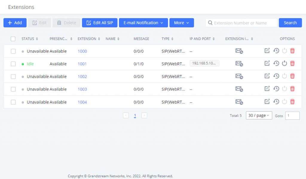
- Status
Users can see the following icon for each extension to indicate the SIP status.
![]() Green: Idle
Green: Idle
![]() Blue: Ringing
Blue: Ringing
![]() Yellow: In Use
Yellow: In Use
![]() Grey: Unavailable (the extension is not registered or disabled on the PBX)
Grey: Unavailable (the extension is not registered or disabled on the PBX)
- Edit single extension
Click on
![]() to start editing the extension parameters.
to start editing the extension parameters.
Click on
![]() to reset the extension parameters to default (except concurrent registration).
to reset the extension parameters to default (except concurrent registration).
Other settings will be restored to default in Maintenance🡪User Management🡪User Information except for username and permissions and delete the user voicemail prompt and voice messages.
- Reboot the user
Click on ![]() to send NOTIFY reboot event to the device that has a IPPBX extension already registered. To successfully reboot the user, “Zero Config” needs to be enabled on the IPPBX Web GUI🡪Device Management🡪Zero Config🡪Zero Config Settings.
to send NOTIFY reboot event to the device that has a IPPBX extension already registered. To successfully reboot the user, “Zero Config” needs to be enabled on the IPPBX Web GUI🡪Device Management🡪Zero Config🡪Zero Config Settings.
- Delete single extension
Click on ![]() to delete the extension. Or select the checkbox of the extension and then click on “Delete Selected Extensions”.
to delete the extension. Or select the checkbox of the extension and then click on “Delete Selected Extensions”.
- Modify selected extensions
Select the checkbox for the extension(s). Then click on “Edit” to edit the extensions in a batch.
- Delete selected extensions
Select the checkbox for the extension(s). Then click on “Delete ” to delete the extension(s).
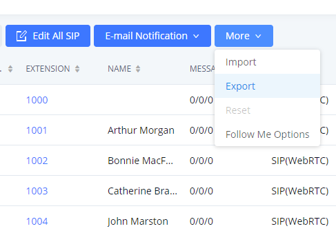
Export Extensions
The extensions configured on the IPPBX can be exported to a CSV format file. Click on the “Export Extensions” button and select technology in the prompt below.
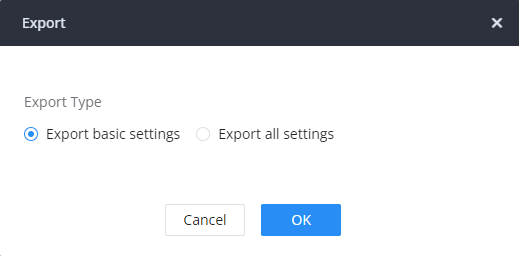
Export Basic Information includes:
- Extension
- CallerID Number
- Privilege
- SIP Password
- AuthID
- Voicemail
- Voicemail Password
- Sync Contact
- First Name
- Last Name
- Email Address
- User/Wave Password
If importing extensions with no values for settings, the following will occur:
- If importing new extensions, or if Replace is selected as the duplicate import option, the default values for those settings will be used.
- If Update is selected as the duplicate import option, no changes will be made to the existing settings.
The exported CSV file can serve as a template for users to fill in desired extension information to be imported to the IPPBX.
Import Extensions
The capability to import extensions to the IPPBX provides users the flexibility to batch-add extensions with similar or different configurations quickly into the PBX system.
- Export the extension CSV file from the IPPBX by clicking on the “Export Extensions” button.
- Fill up the extension information you would like in the exported CSV template.
- Click on the “Import Extensions” button. The following dialog will be prompted.
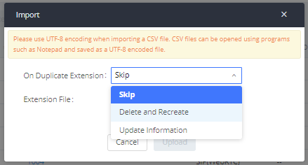
- Select the option in “On Duplicate Extension” to define how the duplicate extension(s) in the imported CSV file should be treated by the PBX.
- Skip: Duplicate extensions in the CSV file will be skipped. The PBX will keep the current extension information as previously configured without change.
- Delete and Recreate: The current extension previously configured will be deleted and the duplicate extension in the CSV file will be loaded to the PBX.
- Update Information: The current extension previously configured in the PBX will be kept. However, if the duplicate extension in the CSV file has a different configuration for any options, it will override the configuration for those options in the extension.
- Click on “Choose file to upload” to select a CSV file from a local directory on the PC.
- Click on “Apply Changes” to apply the imported file on the IPPBX.
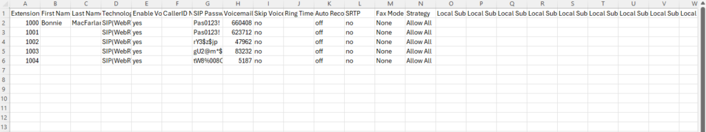
Example of a file to import:
| Field | Supported Values |
|---|---|
Extension | Digits |
Technology | SIP/SIP(WebRTC) |
Enable Voicemail | yes/no/remote |
CallerID Number | Digits |
SIP Password | Alphanumeric characters |
Voicemail Password | Digits |
Skip Voicemail Password Verification | yes/no |
Ring Timeout | Empty/ 3 to 600 (in second) |
SRTP | yes/no |
Skip Trunk Auth | yes/no/bytime |
Codec Preference | PCMU,PCMA,GSM,G.726,G.722,G.729,H.264,ILBC,AAL2-G.726-32,ADPCM,G.723,H.263,H.263p,vp8,opus |
Permission | Internal/Local/National/International |
DTMF Mode | RFC4733/info/inband/auto |
Insecure | Port |
Enable Keep-alive | Yes/no |
Keep-alive Frequency | Value from 1-3600 |
AuthID | Alphanumeric value without special characters |
TEL URI | Disabled/user=phone/enabled |
Call Forward Busy | Digits |
Call Forward No Answer | Digits |
Call Forward Unconditional | Digits |
Support Hot-Desking Mode | Yes/no |
Dial Trunk Password | Digits |
Disable This Extension | Yes/no |
CFU Time Condition | All time/Office time/out of office time/holiday/out of holiday/out of office time or holiday/specific time |
CFN Time Condition | All time/Office time/out of office time/holiday/out of holiday/out of office time or holiday/specific time |
CFB Time Condition | All time/Office time/out of office time/holiday/out of holiday/out of office time or holiday/specific time |
Music On Hold | Default/ringbacktone_default |
CC Agent Policy | If CC is disabled use: never If CC is set to normal use: generic If CC is set to trunk use: native |
CC Monitor Policy | Generic/never |
CCBS Available Timer | 3600/4800 |
CCNR Available Timer | 3600/7200 |
CC Offer Timer | 60/120 |
CC Max Agents | Value from 1-999 |
CC Max Monitors | Value from 1-999 |
Ring simultaneously | Yes/no |
External Number | Digits |
Time Condition for Ring Simultaneously | All time/Office time/out of office time/holiday/out of holiday/out of office time or holiday/specific time |
Time Condition for Skip Trunk Auth | All time/Office time/out of office time/holiday/out of holiday/out of office time or holiday/specific time |
Enable LDAP | Yes/no |
Enable T.38 UDPTL | Yes/no |
Max Contacts | Values from 1-10 |
Enable Wave | Yes/no |
Alert-Info | None/Ring 1/Ring2/Ring3/Ring 4/Ring 5/Ring 6/Ring 7/ Ring 8/Ring 9/Ring 10/bellcore-dr1/bellcore-dr2/ bellcore-dr3/ bellcore-dr4/ bellcore-dr5/custom |
Do Not Disturb | Yes/no |
DND Time Condition | All time/Office time/out of office time/holiday/out of holiday/out of office time or holiday/specific time |
Custom Auto answer | Yes/no |
Do Not Disturb Whitelist | Empty/digits |
User Password | Alphanumeric characters. |
First Name | Alphanumeric without special characters. |
Last Name | Alphanumeric without special characters. |
Email Address | Email address |
Language | Default/en/zh |
Phone Number | Digits |
Call-Barging Monitor | Extensions allowed to call barging |
Seamless Transfer Members | Extensions allowed to seamless transfer |
The CSV file should contain all the above fields, if one of them is missing or empty, the IPPBX will display the following error message for missing fields.

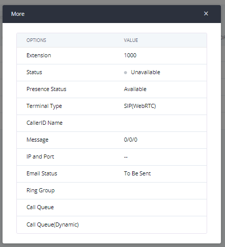
Extension Details
Users can click on an extension number in the Extensions list page and quickly view information about it such as:
- Extension: This shows the Extension number.
- Status: This shows the status of the extension.
- Presence status: Indicates the Presence Status of this extension.
- Terminal Type: This shows the type of the terminal using this extension
- Caller ID Name: Reveals the Caller ID Name configured on the extension.
- Messages: Shows the messages’ stats.
- IP and Port: The IP address and the ports of the device using the extension.
- Email status: Show the Email status (sent, to be sent…etc.).
- Ring Group: Indicates the ring groups that this extension belongs to.
- Call Queue: Indicates the Cal Queues that this extension belongs to.
- Call Queue (Dynamic): Indicates the Call Queues that this extension belongs to as a dynamic agent.
E-mail Notification
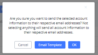
Once the extensions are created with Email addresses, the PBX administrator can click on the button “E-mail Notification” to send the account registration and configuration information to the user. Please make sure the Email setting under Web GUI🡪System Settings🡪Email Settings is properly configured and tested on the IPPBX before using “E-mail Notification”.
When clicking on ”More” > “E-mail Notification” button, the following message will be prompted on the web page. Click on OK to confirm sending the account information to all users’ Email addresses.
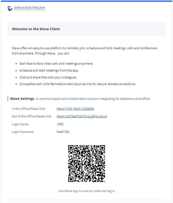
The user will receive an Email including account registration information as well as the Wave Settings with the QR code:
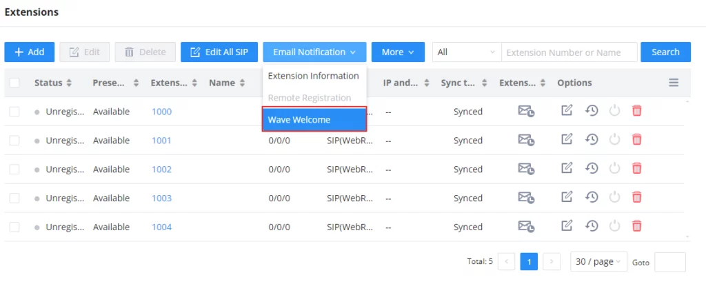
The PBX admin can also send “Extension Information” mail and “Wave Welcome” mail as the figure below shows
SMS Message Support
The IPPBX provides built-in SIP SMS message support. For SIP end devices such as Grandstream GXP or GXV phones that support SIP messages, after a IPPBX account is registered on the end device, the user can send and receive SMS messages. Please refer to the end device documentation on how to send and receive SMS messages.
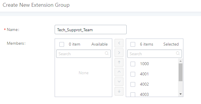
Extension Groups
The IPPBX extension group feature allows users to assign and categorize extensions in different groups to better manage the configurations on the IPPBX. For example, when configuring the “Enable Source Caller ID Whitelist”, users could select a group instead of each person’s extension to assign. This feature simplifies the configuration process and helps manage and categorize the extensions for a business environment.
Configure Extension Groups
Extension groups can be configured via Web GUI🡪Extension/Trunk🡪Extension Groups.
- Click on
 to create a new extension group.
 - Click on
 to edit the extension group.
 - Click on
 to delete the extension group.
Select extensions from the list on the left side to the right side.
Click on ![]()
![]()
![]()
![]() to change the ringing priority of the members selected on the group.
to change the ringing priority of the members selected on the group.
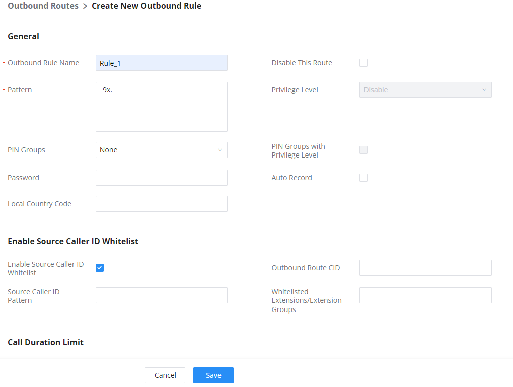
Using Extension Groups
Here is an example where the extension group can be used. Go to Web GUI🡪Extension/Trunk🡪Outbound Routes and select “Enable Source Caller ID Whitelist”. Both single extensions and extension groups will show up for users to select.
VoIP Trunks
VoIP Trunk Configuration
VoIP trunks can be configured in the PBX under Web GUI🡪Extension/Trunk🡪VoIP Trunks. Once created, the VoIP trunks will be listed with the Provider Name, Type, Hostname/IP, Username, and Options to edit/detect the trunk.
- Click on “Add SIP Trunk” to add a new VoIP trunk.
- Click on to configure detailed parameters for the VoIP trunk.
- Click on
 to configure Direct Outward Dialing (DOD) for the SIP Trunk.
 - Click on
 to start LDAP Sync.
 - Click on to delete the VoIP trunk.
The VoIP trunk options are listed in the table below.
Disable This Trunk | Check this box to disable this trunk. |
Type | Select the VoIP trunk type.
|
Provider Name | Configure a unique label (up to 64 characters) to identify this trunk when listed in outbound rules, inbound rules, etc. |
Host Name | Configure the IP address or URL for the VoIP provider’s server of the trunk. |
Transport | Select the transport protocol to use.
|
Keep Original CID | Keep the CID from the inbound call when dialing out. This setting will override the “Keep Trunk CID” option. Please make sure that the peer PBX at the other side supports to match user entry using the “username” field from the authentication line. |
Keep Trunk CID | If enabled, the trunk CID will not be overridden by the extension’s CID when the extension has CID configured. The default setting is “No”. |
TEL URI | If "Enabled" option is selected, TEL URI and Remove OBP from Route cannot be enabled at the same time. If the phone has an assigned PSTN telephone number, this field should be set to "User=Phone". A "User=Phone" parameter will then be attached to the Request-Line and "TO" header in the SIP request to indicate the E.164 number. If set to "Enable", "Tel:" will be used instead of "SIP:" in the SIP request. |
Caller ID Number | Configure the Caller ID. This is the number that the trunk will try to use when making outbound calls. For some providers, it might not be possible to set the CallerID with this option and this option will be ignored. Important Note: When making outgoing calls, the following priority order rule will be used to determine which CallerID will be set before sending out the call: |
CallerID Name | Configure the new name of the caller when the extension has no CallerID Name configured. |
Auto Record | If enabled, calls handled with this extension/trunk will automatically be recorded. |
Auth ID | Enter the Authentication ID for the "Register SIP Trunk" type. |
Direct Callback | Allows external numbers the option to get directed to the extension that last called them. For Example, User 2002 has dialed external number 061234575 but they were not reachable, once they have received missed call notification on their phone, they would mostly call back the number, if the option “Direct Callback” is enabled then they will be directly bridged to user 2002 regardless of the configured inbound destination. |
Domain Connection Mode | If enabled, the following options will be automatically configured: TLS transport, From Domain, Enable Heartbeat Detection and ICE Support. Please ensure that the trunk host name is a GDMS-assigned address and supports TLS. |
Limit Concurrent Calls | If enabled and when the number of concurrent calls exceeds any trunk's configured concurrent call thresholds, an alarm notification will be generated. Note: Please make sure the system alert event "Trunk Concurrent Calls" is enabled. |
Concurrent Call Threshold | Threshold of all incoming and outgoing concurrent calls through this trunk. |
Outgoing Concurrent Calls Threshold | Threshold of all outgoing concurrent calls passing through this trunk. |
Incoming Concurrent Calls Threshold | Threshold of all incoming concurrent calls passing through this trunk. |
Total Time Limit For Outbound Calls | |
Enable Total Time Limit For Outgoing Calls | When this setting is activated, the user can set a time limit before calls cannot be initiated through this trunk |
Period | This setting defines how long until the time allowed for outgoing calls is reset.
Example: If the time limit has been set to 4320 minutes, the allowed time will always revert back to 4320 after a month or 3 month based on the period configured. |
Total Time | Total time allowed in minutes |
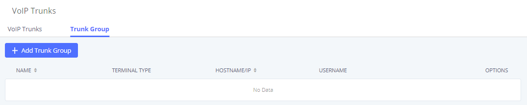
Trunk Group
Users can create VoIP Trunk Groups to register and easily apply the same settings on multiple accounts within the same SIP server. This can drastically reduce the amount of time needed to manage accounts for the same server and improve the overall cleanliness of the web UI.
Once creating the new trunk group and configuring the SIP settings, users can add multiple accounts within the configured SIP server by pressing the ![]() button and configuring the username, password, and authentication ID fields.
button and configuring the username, password, and authentication ID fields.
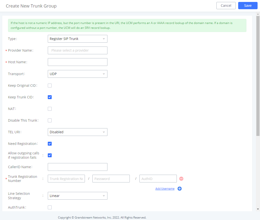
Type | Register Trunk |
Provider Name | Configure a unique label to identify the trunk when listed in outbound rules and incoming rules. |
Host Name | Enter the IP address or hostname of the VoIP provider's server. |
Transport | Configure the SIP Transport method. Using TCP requires local TCP support; using TLS requires local TLS support. |
Keep Original CID | Keep CID from the inbound call when dialing out even if option "Keep Trunk CID" is enabled. Please make sure the peer PBX at the other end supports matching user entry using the "username" field from the authentication line. |
Keep Trunk CID | Always use trunk CID if specified even if extension has DOD number or CID configured. |
NAT | Enable this setting if the IPPBX is using public IP and communicating with devices behind NAT. |
Disable This Trunk | Check this box to disable this trunk |
TEL URI | if "Enabled" option is selected, TEL URI and remove OBP from Route cannot be enabled at the same time. If the phone has an assigned PSTN telephone number, this field should be set to "User=Phone". A "User=Phone" parameter will the be attached to the Request-Line and "TO" header in the SIP request to indicate the E.164 number. If set to "Enable", "Tel:" will be used instead of "SIP:" in the SIP request. |
Need Registration | Whether to register on the external server. |
Allow outgoing calls if registration fails | Uncheck to block outgoing cakks if registration fails. If "Need Registration" option is unchecked, this settting will be ignored. |
CallerID Name | To display the caller ID name of the trunk, you must configure the caller ID number of the trunk. |
Trunk Registration Number | The number used to register with the provider server, and the VoIP provider will authenticate the number based on the trunk registration number. |
Line Selection Strategy | Linear: Select lines in list order and make Outbound calls. Round Robin: Rotary line selection with memory and making Outboun calls. |
AuthTrunk | If enabled, the IPPBX will send a 401 response to the incming call to authenticate the trunk. |
Auto Record | If enabled, calls handled with this extension/trunk will automatically be recorded. |
Direct Callback | Allows external numbers the option to get directed to the extension that last called them. |
RemoteConnect Mode | If enabled, RemoteConnect-related options will be automatically configured. Please confirm the trunk has a GDMS-assigned address or supports TLS. |
Monitor Concurrent Calls | If enabled, the number of concurrent calls on this trunk will be monitored. If the "Trunk Concurrent Calls" system alert is enabled, alert notifications will be generated if the number of concurrent calls exceeds this trunk's configured concurrent call thresholds. |
Concurrent Call Threshold | Threshold of all incoming and outgoing concurrent calls in this trunk. |
Outgoing Concurrent Call Threshold | Threshold of all outgoing concurrent calls passing through this trunk. |
Incoming Concurrent Call Threshold | Threshold of all incoming concurrent calls passing through this trunk. |
Enable Total Time Limit For Outbound Calls | If enabled, a limit will be placed on the cumulative duration of outbound calls within a specific period. Once this limit has been reached, further outbound calls from this trunk will not be allowed. |
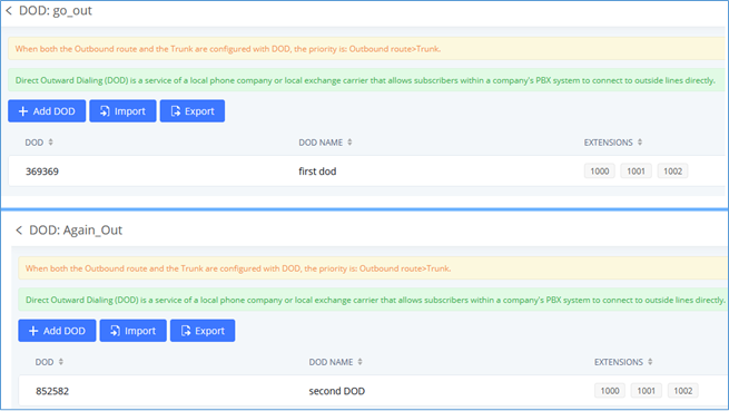
Direct Outward Dialing (DOD)
The IPPBX provides Direct Outward Dialing (DOD), which is a service of a local phone company (or local exchange carrier) that allows subscribers within a company’s PBX system to connect to outside lines directly.
Example of how DOD is used:
Company ABC has a SIP trunk. This SIP trunk has 4 DIDs associated with it. The main number of the office is routed to an auto attendant. The other three numbers are direct lines to specific users of the company. Now when a user makes an outbound call their caller ID shows up as the main office number. This poses a problem, as the CEO would like their calls to come from their direct line. This can be accomplished by configuring DOD for the CEO’s extension.
Steps to configure DOD:
- To setup DOD go to IPPBX Web GUI🡪Extension/Trunk🡪VoIP Trunks page.
- Click to access the DOD options for the selected SIP Trunk.
- Click “Add DOD” to begin your DOD setup
- Enter a SIP trunk DID number in the “DOD number” field. In this example, ABC company has a total of 4 DID numbers. Enter the phone number used by the CEO here.
- When adding extensions, you can choose whether to “Enable Strip” according to your needs. If it is enabled, you can configure the number (0-64) that will be stripped from the extension number before being added to the DOD number. For example, if the entered digit is 2, and the DOD number for extension 4002 is 1122, then dialing out from 4002, 112202 will be used as the caller ID (DOD).
- Select an extension from the “Available Extensions” list. Users have the option of selecting more than one extension. In this case, Company ABC would select the CEO’s extension. After making the selection, click on the button to move the extension(s) to the “Selected Extensions” list.
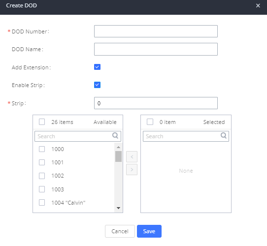
- Click “Save” at the bottom.
Once completed, the user will return to the EDIT DOD page which shows all the extensions that are associated with a particular DOD.
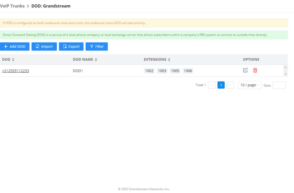
![]() : Add a DOD.
: Add a DOD.![]() : Import DODs using a csv file.
: Import DODs using a csv file.![]() : Export the DODs using a csv file.
: Export the DODs using a csv file.![]() : Filter DODs by number or name.
: Filter DODs by number or name.
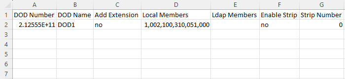
For DOD importing, please refer to the screenshot below for the template used.
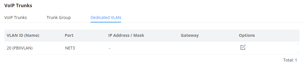
Dedicated VLAN
In this section the user can configure the IP address for the dedicated VLAN for the IPPBX operations. This section can be configured after creating the module on the networking module. For more information, please refer to the following link: https://documentation.grandstream.com/knowledge-base/gcc60xx-networking-user-manual/#pbx-vlan
WebRTC Trunks
WebRTC, Web Real-Time Communication, is a real-time audio/video chatting framework that allows real-time audio/video chatting through the web browser. WebRTC usually does not refer to the web application itself but to the set of protocols and practices bundled with a graphical interface. Our IPPBX supports creating WebRTC trunks to use exclusively with web applications, this allows the users to join calls and meetings just by clicking a link to a web page.
Below is a figure that shows the options to configure when setting up this feature:
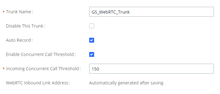
Trunk Name | Create a unique label to easily identify the trunk for inbound route configuration. |
Disable This Trunk | Check this box to disable this trunk. |
Auto Record | If enabled, calls handled with this extension/trunk will automatically be recorded. |
Jitter Buffer | Select jitter buffer method for temporary accounts such as meeting participants who joined via link. Disable: Jitter buffer will not be used. Fixed: Jitter buffer with a fixed size (equal to the value of "Jitter Buffer Size") Adaptive: Jitter buffer with a adaptive size that will not exceed the value of "Max Jitter Buffer"). NetEQ: Dynamic jitter buffer via NetEQ. |
Monitor Concurrent Calls | If enabled, the number of concurrent calls on this trunk will be monitored. If the "Trunk Concurrent Calls" system alert is enabled, alert notifications will be generated if the number of concurrent calls exceeds this trunk's configured concurrent call thresholds. |
Incoming Concurrent Call Threshold | Threshold of all incoming concurrent calls passing through this trunk. |
WebRTC Inbound Link Address | This link can be embedded onto a web page. Clicking the link will connect to a pre-configured WebRTC trunk destination. You can also enter this link in the browser address bar to directly access and test WebRTC calls. |
Outbound Routes
In the following sections, we will discuss the steps and parameters used to configure and manage outbound rules in IPPBX, these rules are the regulating points for all external outgoing calls initiated by the IPPBX through SIP trunks
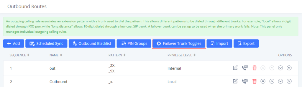
Configuring Outbound Routes
In the IPPBX, an outgoing calling rule pairs an extension pattern with a trunk used to dial the pattern. This allows different patterns to be dialed through different trunks (e.g., “Local” 7-digit dials through an FXO while “long-distance” 10-digit dials through a low-cost SIP trunk). Users can also set up a fail-over trunk to be used when the primary trunk fails.
Go to Web GUI🡪Extension/Trunk🡪Outbound Routes to add and edit outbound rules.
- Click on to add a new outbound route.
- Click the “Import” button to upload the outgoing route in .CSV format.
- Click the “Export” button to generate outgoing routes in .CSV format.
- Click to edit the outbound route.
- Click to delete the outbound route.
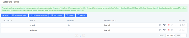
On the IPPBX, the outbound route priority is based on the “Best matching pattern”. For example, the IPPBX has outbound route A with pattern 1xxx and outbound route B with pattern 10xx configured. When dialing 1000 for an outbound call, outbound route B will always be used first. This is because pattern 10xx is a better match than pattern 1xxx. Only when there are multiple outbound routes with the same pattern configured.
Outbound Rule Name | Configure the name of the calling rule (e.g., local, long_distance, etc.). Letters, digits, _ and – are allowed. |
All patterns are prefixed by the “_” character, but please do not enter more than one “_” at the beginning. All patterns can add comments, such as “_pattern /* comment */”. In patterns, some characters have special meanings:
| |
After creating the outbound route, users can choose to enable and disable it. If the route is disabled, it will not take effect anymore. However, the route settings will remain in IPPBX. Users can enable it again when it is needed. | |
Password | Configure the password for users to use this rule when making outbound calls. |
If your local country code is affected by the outbound blacklist, please enter it here to bypass the blacklist. | |
Call Duration Limit | Enable to configure the maximum duration for the call using this outbound route. |
Maximum Call Duration | Configure the maximum duration of the call (in seconds). The default setting is 0, which means no limit. |
Warning Time | Configure the warning time for the call using this outbound route. If set to x seconds, the warning tone will be played to the caller when x seconds are left to end the call. |
If enabled, calls using this route will automatically be recorded. | |
Warning Repeat Interval | Configure the warning repeat interval for the call using this outbound route. If set to X seconds, the warning tone will be played every x seconds after the first warning. |
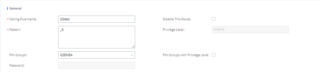
PIN Groups | Select a PIN Group |
PIN Groups with Privilege Level | If enabled and PIN Groups are used, Privilege Levels and Filter on Source Caller ID will also be applied. |
Privilege Level | Select the privilege level for the outbound rule.
Please be aware of the potential security risks when using the “Internal” level, which means all users can use this outbound rule to dial out from the trunk. |
Enable Filter on Source Caller ID | When enabled, users could specify extensions allowed to use this outbound route. “Privilege Level” is automatically disabled if using “Enable Filter on Source Caller ID”. The following two methods can be used at the same time to define the extensions as the source caller ID.
X: Any Digit from 0-9. Z: Any Digit from 1-9. N: Any Digit from 2-9. “.“: Wildcard. Match one or more characters. “!“: Wildcard. Match zero or more characters immediately. Example: [12345–9] – Any digit from 1 to 9. Note: Multiple patterns can be used. Patterns should be separated by a comma “,”. Example: _X. , _NNXXNXXXXX, _818X. |
Outbound Route CID | Attempt to use the configured outbound route CID. This CID will not be used if DOD is configured. |
Send This Call Through Trunk | |
Trunk | Select the trunk for this outbound rule. |
Strip | Allows the user to specify the number of digits that will be stripped from the beginning of the dialed string before the call is placed via the selected trunk. Example: The users will dial 9 as the first digit of long-distance calls. In this case, 1 digit should be stripped before the call is placed. |
Prepend | Specify the digits to be prepended before the call is placed via the trunk. Those digits will be prepended after the dialing number is stripped. |
Failover Trunk | Failover trunks can be used to make sure that a call goes through an alternate route when the primary trunk is busy or down. If “Use Failover Trunk” is enabled and “Failover trunk” is defined, the calls that cannot be placed via the regular trunk may have a secondary trunk to go through. IPPBX supports up to 10 failover trunks. Example: The user’s primary trunk is a VoIP trunk, and the user would like to use the PSTN when the VoIP trunk is not available. The PSTN trunk can be configured as the failover trunk of the VoIP trunk. |
Strip | Allows the user to specify the number of digits that will be stripped from the beginning of the dialed string before the call is placed via the selected trunk. Example: The users will dial 9 as the first digit of long-distance calls. In this case, 1 digit should be stripped before the call is placed. |
Prepend | Specify the digits to be prepended before the call is placed via the trunk. Those digits will be prepended after the dialing number is stripped. |
Time Condition | |
Time Condition Mode | Use Main Trunk or Failover Trunk: Use the Main Trunk and its settings during the configured time conditions. If the main trunk is unavailable, the Failover Trunk and its settings will be used instead. Use Specific Trunks: Use specific trunks during the configured time conditions. The Strip and Prepend settings of the Main Trunk will be used. If a trunk is unavailable during its time condition, no failover trunks will be used. |
Failover Trunk Toggles
This option controls whether failover trunks will be used if receiving specific responses to outgoing calls.
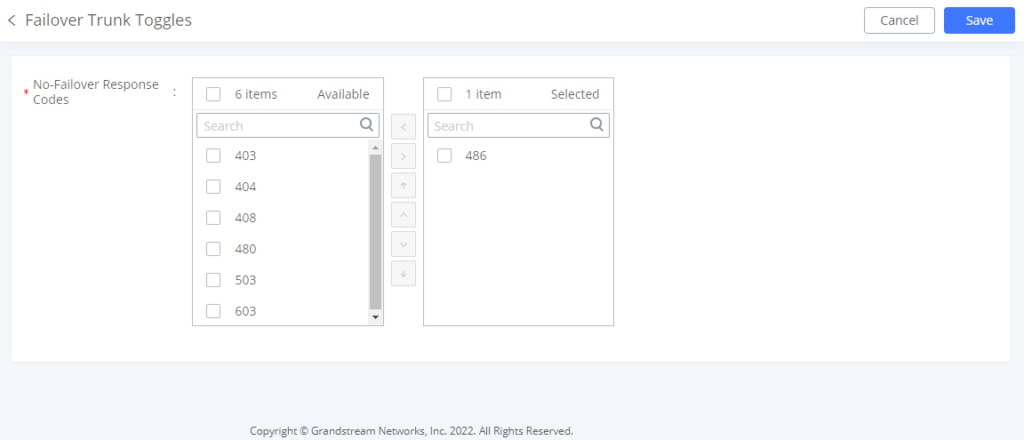
If a call receives the selected response codes, the IPPBX will redirect it to the call route’s failover trunk.
Outbound Routes DOD
It is possible to specify the DOD number based on the Outbound Route, as displayed in the screenshot below. For each outbound route.
Outbound Blacklist
The IPPBX allows users to configure a blacklist for outbound routes. If the dialing number matches the blacklist numbers or patterns, the outbound call will not be allowed. The outbound blacklist can be configured under IPPBX Web GUI > Extension/Trunk > Outbound Routes: Outbound Blacklist.
Users can configure numbers, patterns or select country code to add to the blacklist. Please note that the blacklist settings apply to all outbound routes.
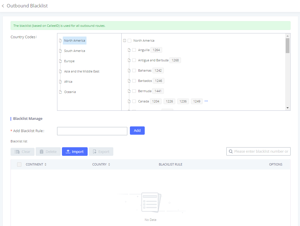
Users can export outbound route blacklists and delete all blacklist entries. Additionally, users can also import blacklists for outbound routes.
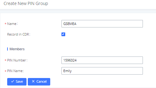
PIN Groups
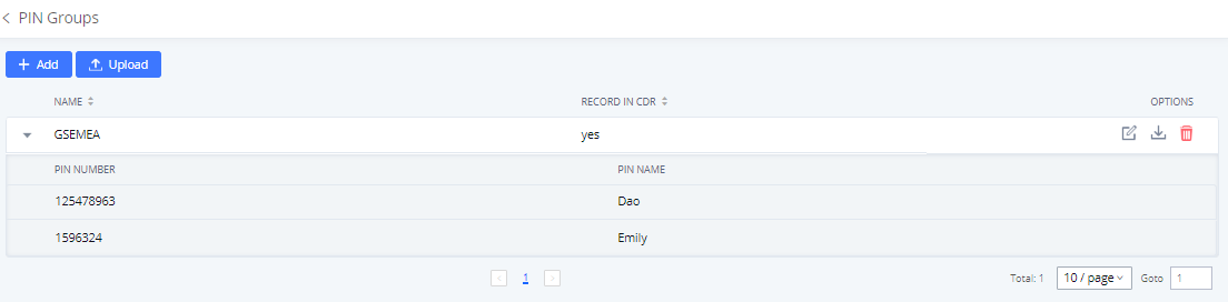
The IPPBX supports the pin group. Once this feature is configured, users can apply pin groups to specific outbound routes. When placing a call on pin-protected outbound routes, the caller will be asked to input the group PIN, this feature can be found on the Web GUI > Extension/Trunk > Outbound Routes > PIN Groups.
Name | Specify the name of the group |
Record In CDR | Specify whether to enable/disable the record in CDR |
PIN Number | Specify the code that will be asked once dialing via a trunk |
PIN Name | Specify the name of the PIN |
Once the user clicks
![]() , the following figure shows to configure the new PIN.
, the following figure shows to configure the new PIN.
The following screenshot shows an example of created PIN Groups and members:
If the PIN group is enabled on the outbound route level, the password, privilege level and enable the filter on source caller ID will be disabled, unless you check the option “PIN Groups with Privilege Level” where you can use the PIN Groups and Privilege Level or PIN Groups and Enable Filter on Source Caller ID.
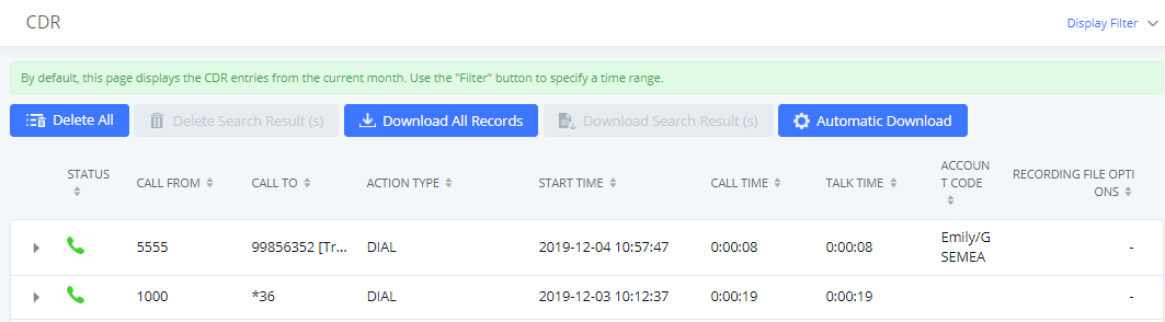
If PIN group CDR is enabled, the call with PIN group information will be displayed as part of CDR under the Account Code field.
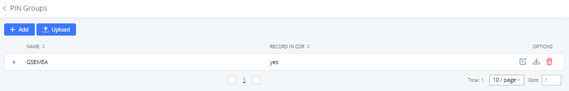
Users can also import PIN Groups by uploading CSV files for each group. To do this:
- Navigate to Extension/Trunk🡪Outbound Routes🡪PIN Groups and click on the “Upload” button.
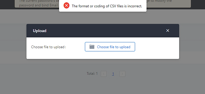
- Select the CSV file to upload. Incorrect file formats and improperly formatted CSV files will result in error messages such as the one below:
- To ensure a successful import, please follow the format in the sample image below
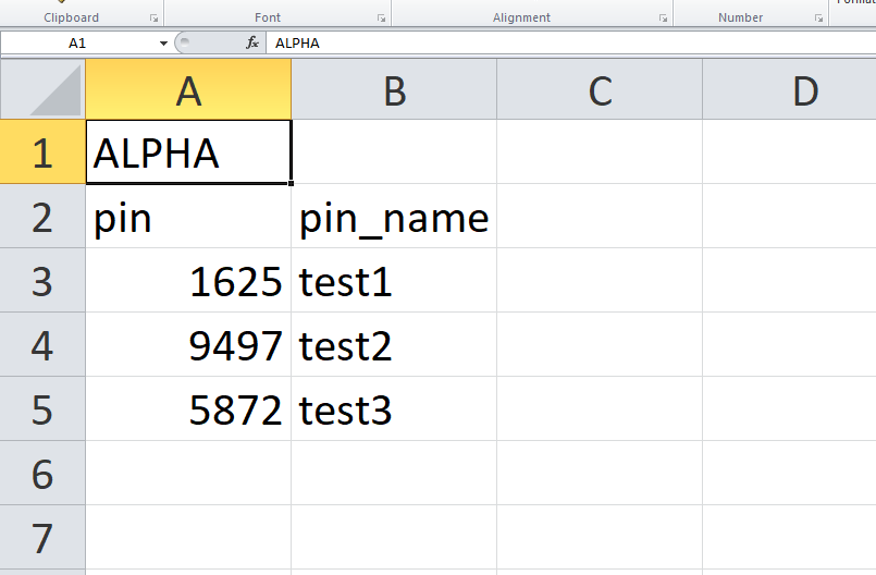
- The top-left value (A1) is the PIN Group name. In this case, it is “ALPHA”.
- Row 2 contains the labels for the modifiable fields: pin and pin_name. These values should not be changed and will cause an upload error otherwise.
- Rows 3+ contain the user-defined values with Column A holding the PINs and Column B holding the PIN names. PIN values must consist of at least four digits.
- Once the file is successfully uploaded, the entry will be added to the list of PIN Groups.

Inbound Routes
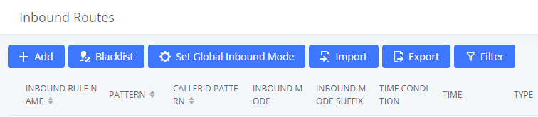
Inbound routes can be configured via Web GUI🡪Extension/Trunk🡪Inbound Routes.
- Click on to add a new inbound route.
- Click on “Blacklist” to configure the blacklist for all inbound routes.
- Click on to edit the inbound route.
- Click on to delete the inbound route.
Inbound Route Configuration
Trunks | Select the trunk to configure the inbound rule. |
Inbound Route Name | Configure the name of the Inbound Route. For example, “Local”, “LongDistance” etc. |
Pattern | All patterns are prefixed with the “_”. Special characters: X: Any Digit from 0-9. Z: Any Digit from 1-9. N: Any Digit from 2-9. “.“: Wildcard. Match one or more characters. “!“: Wildcard. Match zero or more characters immediately. Example: [12345-9] – Any digit from 1 to 9. Notes: Example: |
Disable This Route | After creating the inbound route, users can choose to enable and disable it. If the route is disabled, it will not take effect anymore. However, the route settings will remain in UCM. Users can enable it again when it is needed. |
CID Source | Configures the source of the CID to match with the configured CallerID Pattern. |
Seamless Transfer Whitelist | Allows the selected extension to use this function. If an extension is busy, and a mobile phone is bound to that extension, the mobile phone can pick up calls to that extension. |
Ringback tone | Choose the custom ringback tone to play when the caller reaches the route. |
Auto Record | If enabled, calls using this route will automatically be recorded. |
Block Collect Call | If enabled, collect calls will be blocked. Note: Collect calls are indicated by the header “P-Asserted-Service-Info: service-code=Backward Collect Call, P-Asserted-Service-Info: service-code=Collect Call”. |
Alert-Info | Configure the Alert-Info, when UCM receives an INVITE request, the Alert-Info header field specifies an alternative ring tone to the UAS. |
Fax Detection | If enabled, fax signals from the trunk during a call will be detected. |
Fax Destination | Configures the destination of faxes.
Note: please make sure the sending email address is correctly configured in System Settings->Email Settings. |
Auto Answer | If enabled, the UCM will automatically answer calls and receive faxes through the inbound route. If disabled, the UCM will not receive a fax until after the call has been answered. Enabling this option will slow down the answering of non-fax calls on the inbound route. The alert tone heard during the detection period can be customized. |
Block Collect Calls | If enabled, collect calls will be blocked. |
Prepend Trunk Name | If enabled, the trunk name will be added to the caller id name as the displayed caller id name. |
Set Caller ID Info | Manipulates Caller ID (CID) name and/or number within the call flow to help identify who is calling. When enabled two fields will show allowing to manipulate the CalleID Number and the Caller ID Name. |
CallerID Number | Configure the pattern-matching format to manipulate the numbers of incoming callers or to set a fixed CallerID number for calls that go through this inbound route.
|
CallerID Name | The default string is ${CALLERID(name)},which means the name of an incoming caller, it is a pattern-matching syntax format. A${CALLERID(name)}B means Prepend a character ‘A’ and suffix a character ‘B’ to ${CALLERID(name)}. Not using pattern-matching syntax means setting a fixed name to the incoming caller. |
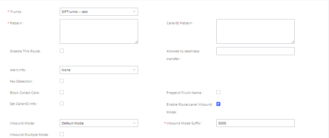
Enable Route-Level Inbound Mode | Gives uses the ability to configure inbound mode per individual route. When enabled two fields will show allowing to set the Inbound mode and the Inbound mode Suffix. Note: Global inbound mode must be enabled before users can configure route-level inbound mode. |
Inbound Mode | Choose the inbound mode for this route. Note: Toggling the global inbound mode will not affect routes that have Route-level Inbound Mode enabled. If all routes have the option enabled, toggling the global inbound mode via BLF will trigger a voice prompt indicating that none of the routes will be affected by the global inbound mode change. |
Inbound Mode Suffix | Dial “Global Inbound Mode feature code + Inbound Mode Suffix” or a route’s assigned suffix to toggle the route’s inbound mode. The BLF subscribed to the inbound mode suffix can monitor the current inbound mode. |
Inbound Multiple Mode | Multiple mode allows users to switch between destinations of the inbound rule by feature codes. Configure related feature codes as described in [Inbound Route: Multiple Mode]. If this option is enabled, the user can use feature code to switch between different modes/destinations. |
CallerID Name Lookup | If enabled, the callerID will be resolved to a name through local LDAP. Note, if a matched name is found, the original callerID name will be replaced. The name lookup is performed before other callerID or callerID name modifiers (e.g., Inbound Route's Set CallerID Info or Prepend Trunk Name). Note: Name lookup may impact system performance. |
Dial Trunk | This option shows up only when “By DID” is selected. If enabled, the external users dialing into the trunk via this inbound route can dial outbound calls using the UCM’s trunk. |
Privilege Level | This option shows up only when “By DID” is selected.
|
Allowed DID Destination | This option shows up only when “By DID” is selected. This controls the destination that can be reached by the external caller via the inbound route. The DID destination is:
|
Default Destination | Select the default destination for the inbound call.
When “By DID” is used, the UCM will look for the destination based on the number dialed, which could be local extensions, conference, call queue, ring group, paging/intercom group, IVR, and voicemail groups as configured in “DID destination”. If the dialed number matches the DID pattern, the call will be allowed to go through.
|
Strip | Specify the digits to be prepended before the call is placed via the trunk. Those digits will be prepended after the dialing number is stripped. |
Prepend | Specify the digits to be prepended before the call is placed via the trunk. Those digits will be prepended after the dialing number is stripped. |
Time Condition | |
Start Time | Select the start time “hour:minute” for the trunk to use the inbound rule. |
End Time | Select the end time “hour:minute” for the trunk to use the inbound rule. |
Date | Select “By Week” or “By Day” and specify the date for the trunk to use the inbound rule. |
Week | Select the day in the week to use the inbound rule. |
Destination | Select the destination for the inbound call under the defined time condition.
When “By DID” is used, the UCM will look for the destination based on the number dialed, which could be local extensions, conference, call queue, ring group, paging/intercom group, IVR, and voicemail groups as configured in “DID destination”. If the dialed number matches the DID pattern, the call will be allowed to go through. Configure the number of digits to be stripped in the “Strip” option.
|
Inbound Route: Prepend Example
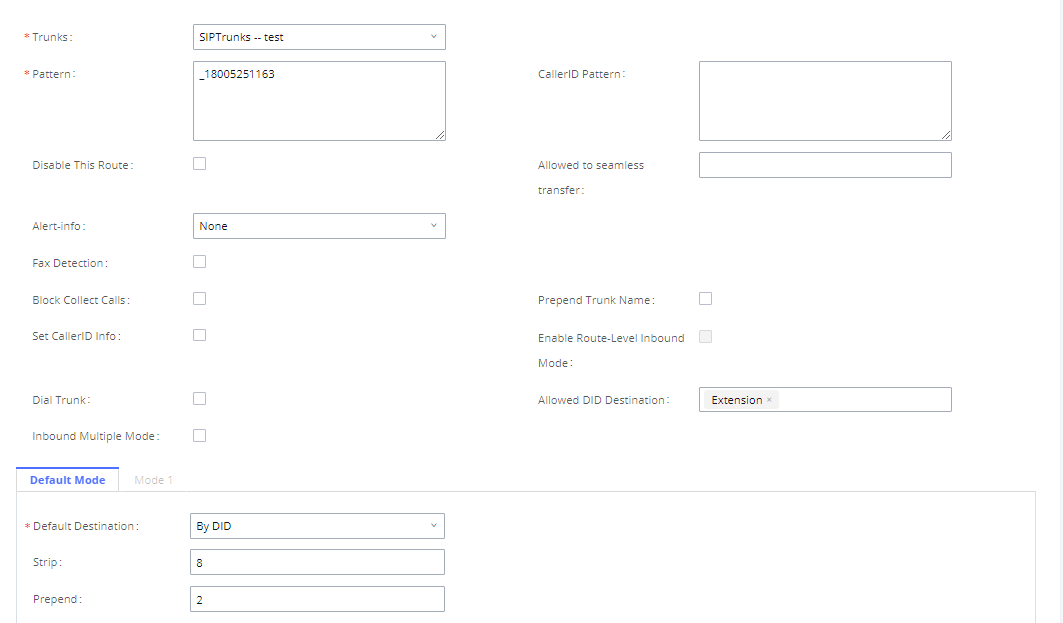
The IPPBX allows users to prepend digits to an inbound DID pattern, with strip taking precedence over prepend. With the ability to prepend digits in the inbound route DID pattern, the user no longer needs to create multiple routes for the same trunk to route calls to different extensions. The following example demonstrates the process:
- If Trunk provides a DID pattern of 18005251163.
- If Strip is set to 8, IPPBX will strip the first 8 digits.
- If Prepend is set to 2, IPPBX will then prepend a 2 to the stripped number, now the number becomes 2163.
- The IPPBX will forward the incoming call to extension 2163.
Inbound Route: Multiple Mode
In the IPPBX, the user can configure an inbound route to enable multiple mode to switch between different destinations. The inbound multiple mode can be enabled under Inbound Route settings.
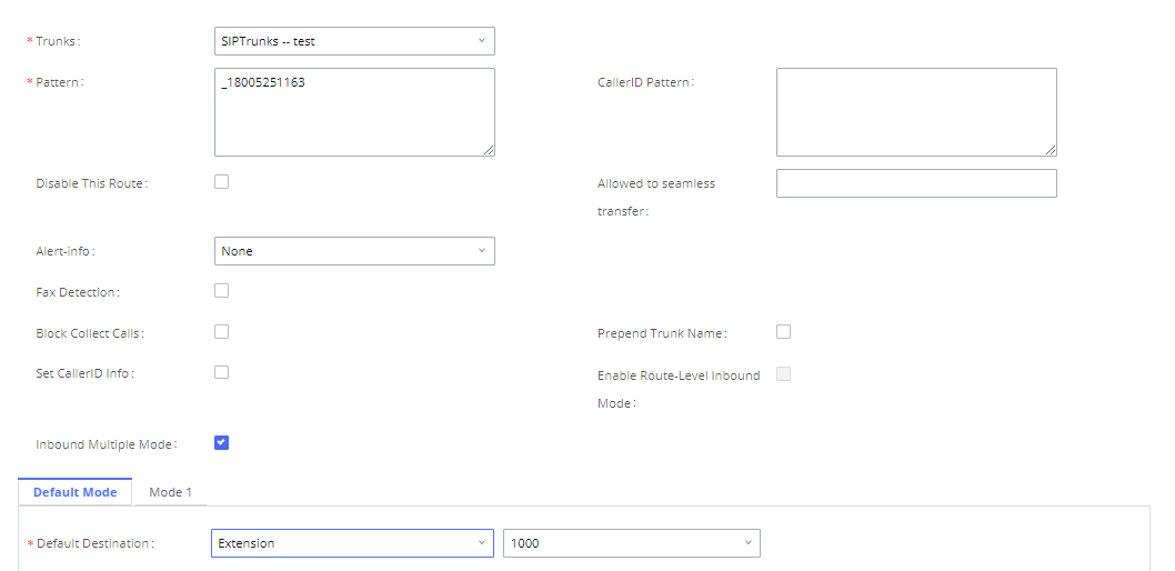
When Multiple Mode is enabled for the inbound route, the user can configure a “Default Destination” and a “Mode 1” destination for all routes. By default, the call coming into the inbound routes will be routed to the default destination.
SIP end devices that have registered on the IPPBX can dial feature code *62 to switch to the inbound route “Mode 1” and dial feature code *61 to switch back to “Default Destination”. Switching between different modes can be easily done without a Web GUI login.
For example, the customer service hotline destination has to be set to a different IVR after 7 PM. The user can dial *62 to switch to “Mode 1” with that IVR set as the destination before off work.
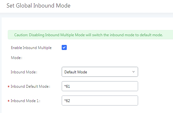
To customize feature codes for “Default Mode” and “Mode 1”, click on ![]() under the “Inbound Routes” page, check the “Enable Inbound Multiple Mode” option, and change “Inbound Default Mode” and “Inbound Mode 1” values (By default, *61 and *62 respectively).
under the “Inbound Routes” page, check the “Enable Inbound Multiple Mode” option, and change “Inbound Default Mode” and “Inbound Mode 1” values (By default, *61 and *62 respectively).
Inbound Route: Route-Level Mode
In the IPPBX, users can enable Route-Level Inbound Mode to switch between different destinations for each inbound route. The inbound Route-Level mode can be enabled under Inbound Route settings.
The global inbound mode must be enabled before configuring Route-Level Inbound Mode. Additionally, Mode 1 must be configured as well.
When Route-Level Inbound Mode is enabled, the user can configure a “Default Destination” and a “Mode 1” destination for each specific route. By default, the call coming into this specific inbound route will be routed to the default destination.
Users can toggle the route’s inbound mode by dialing “Global Inbound Mode feature code + Inbound Mode Suffix” and the current inbound route can be monitored by subscribing a BLF to the Inbound Mode Suffix.
For example, the Inbound Default Mode feature code is set to *61 and the Inbound Mode suffix for route 1 is set to 1010. To switch the mode of route 1 to Default Mode, users can dial *611010.
Note: Toggling the global inbound mode will not affect routes that have Route-level Inbound Mode enabled. If all routes have the option enabled, toggling the global inbound mode via BLF will trigger a voice prompt indicating that none of the routes will be affected by the global inbound mode change.
Inbound Route: Inbound Mode BLF Monitoring
Users can assign MPKs and VPKs to monitor and toggle the current global inbound mode of the IPPBX.
To do this, please refer to the following steps:
- Access the IPPBX web GUI and navigate to Extension/Trunk🡪Inbound Routes.
- Click on the
 button and enable Inbound Multiple Mode.
 - Edit the subscribe number field to the desired BLF value.
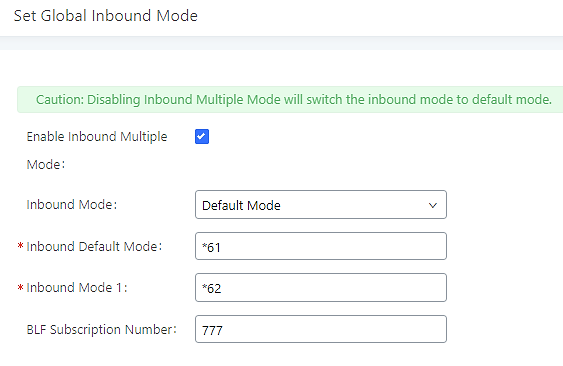
- Configure the BLF value on a phone’s MPK/VPK. As an example, a GXP2140 with the BLF configured will show the Inbound Mode status on its screen once configured. The 777 BLF is lit green, indicating that the current inbound mode is “Default Mode”.
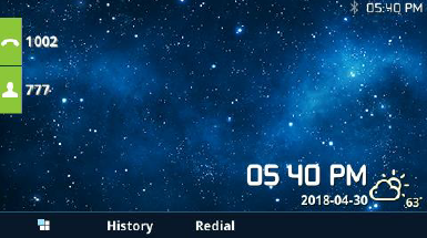
- Pressing the key will toggle the inbound mode to “Mode 1”, and the button’s color will change to red.
Inbound Route: Import/Export Inbound Route
Users can now import and export inbound routes to quickly set up inbound routing on a IPPBX or to back up an existing configuration. An exported inbound route configuration can be directly imported without needing any manual modifications.
The imported file should be in CSV format and using UTF-8 encoding, the imported file should contain the below columns, and each column should be separated by a comma (It is recommended to use Notepad++ for the imported file creation):
- Disable This Route: Yes/No.
- Pattern: Always prefixed with _
- CallerID Pattern: Always prefixed with _
- Prepend Trunk Name: Yes/No.
- Prepend User Defined Name Enable: Yes/No.
- Prepend User Defined Name: A string.
- Alert-info: None, Ring 1, Ring 2… The user should enter an Alert-info string following the values we have in the Inbound route Alert-Info list.
- Allowed to seamless transfer: [Extension_number]
- Inbound Multiple Mode: Yes/No.
- Default Destination: By DID, Extension, Voicemail… Users should enter a Default Destination string following the values we have in the Inbound route Default Destination list.
- Destination: An Extension number, Ring Group Extension…
- Default Time Condition.
- Mode 1: By DID, Extension, Voicemail… Users should enter a Default Destination string following the values we have in the mode 1 Default Destination list.
- Mode 1 Destination: An Extension number, Ring Group Extension…
- Mode 1 Time Condition.
Blacklist Configurations
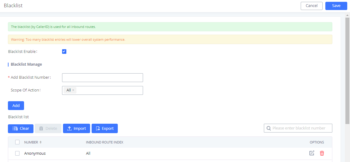
In the IPPBX, Blacklist is supported for all inbound routes. Users could enable the Blacklist feature and manage the Blacklist by clicking on “Blacklist”.
- Select the checkbox for “Blacklist Enable” to turn on the Blacklist feature for all inbound routes. The blacklist is disabled by default.
- Enter a number in the “Add Blacklist Number” field and then click ”Add” to add to the list. Anonymous can also be added as a Blacklist Number by typing “Anonymous” in Add Blacklist Number field.
- To remove a number from the Blacklist, select the number in the “Blacklist list” and click on or click on the” Clear” button to remove all the numbers on the blacklist.
- Users can also export the inbound route blacklist by pressing the
 button.
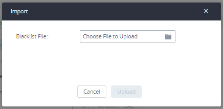
- To add blacklisted numbers in batch, click on “Import” to upload the blacklist file in CSV format. The supported CSV format is as below.

CALL FEATURES
Multimedia Meeting
The IPPBX supports multimedia meeting room allowing multiple rooms used at the same time.
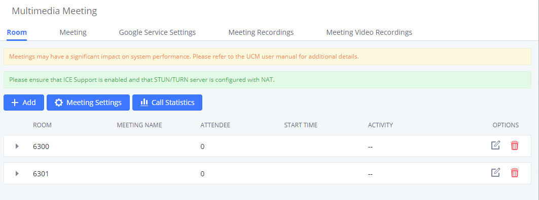
The multimedia meeting room configurations can be accessed under Web GUI🡪Call Features🡪 Multimedia Meeting. On this page, users can create, edit, view, invite, manage the participants, and delete multimedia meeting rooms. The multimedia meeting room status and meeting call recordings (if recording is enabled) will be displayed on this web page as well.
For video meeting, which is based on WebRTC, participants can join the meeting from a PC without installing extra plug-ins or software.
The IPPBX admin can create multiple multimedia meeting rooms for users to dial in.
Meeting room specifications affect user participation to a certain extent. IPPBX supports the forecasting of meeting resources. There will be corresponding judgments and adjustments in the following scenarios:
- When meeting resources are used up, scheduled meeting members cannot join the meeting in advance.
- When a point-to-point call is transferred to a conference, the conference resources are used up.
- When meeting resources are used up, do not join a group IM chat when you initiate a meeting.
- When meeting resources are used up, do not join an instant meeting.
- Close other instant meetings or scheduled meetings that have timed out to ensure that invited members can join the scheduled meeting.
- In an ongoing meeting, if the number of invited members exceeds the upper limit, members cannot be invited to join the meeting.
- Enable flow control for videos and presentations in the conference room.
Multimedia Room Configurations
- Click on “Add” to add a new meeting room.
- Click on to edit the meeting room.
- Click on to delete the meeting room.
Meeting Settings contains the following options:
Log in to the IPPBX Web GUI and open the Call Features 🡪 Multimedia Meeting page to manage the conference room. Users can create, edit, view, invite, manage meeting members, and delete meeting rooms. The conference room status and conference call recording (if the recording function is enabled) will be displayed on the page. The meeting rooms in the list include public meeting rooms and random meeting rooms. For temporary meeting room administrators, only the “batch kicking people” function is supported. The temporary meeting room has no meeting password or host code. The member who initiates the group meeting is the host, and ordinary members have the right to invite.
Meetings Settings
To edit the general settings of the meeting rooms created in the IPPBX, the user can click on “Meetings Settings” button under the Room tab.
Multimedia Meeting Call Operations
Join a Meeting Call
Users could dial the meeting room extension to join the meeting. If the password is required, enter the password to join the meeting as a normal user, or enter the admin password to join the meeting as an administrator.
Invite Other Parties to Join a Meeting
When using the IPPBX meeting room., there are two ways to invite other parties to join the meeting.
- Invite from Web GUI.
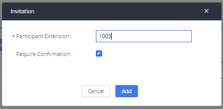
For each meeting room in PBX Web GUI🡪Call Features🡪 Multimedia Meeting, there is an icon ![]() for option “Invite a participant”. Click on it and enter the number of the party you would like to invite. Then click on “Add”. A call will be sent to this number to join the conference.
for option “Invite a participant”. Click on it and enter the number of the party you would like to invite. Then click on “Add”. A call will be sent to this number to join the conference.
- Invite by dialing 0 or 1 during a conference call.
A meeting participant can invite other parties to the meeting by dialing from the phone during the meeting call. Please make sure the option “Enable User Invite” is turned on for the meeting room first. Enter 0 or 1 during the meeting call. Follow the voice prompt to input the number of the party you would like to invite. A call will be sent to this number to join the meeting.
0: If 0 is entered to invite another party, once the invited party picks up the invitation call, permission will be asked to “accept” or “reject” the invitation before joining the conference.
1: If 1 is entered to invite another party, no permission will be required from the invited party.
During The Meeting
During the meeting call, users can manage the conference from Web GUI or IVR.
- Manage the meeting call from Web GUI.
Log in IPPBX Web GUI during the meeting call, and the participants in each meeting room will be listed.
- Click on
 to kick a participant from the meeting.
 - Click on
 to mute the participant.
 - Click on
 to lock this meeting room so that other users cannot join it anymore.
 - Click on
 to invite other users into the meeting room.
 - Click on
 to Invite meeting rooms or Invite contact groups.
- Manage the meeting call from IVR.
Please see the options listed in the table below.
Meeting Administrator IVR Menu | |
1 | Mute/unmute yourself. |
2 | Lock/unlock the conference room. |
3 | Kick the last joined user from the conference. |
4 | Decrease the volume of the conference call. |
5 | Decrease your volume. |
6 | Increase the volume of the conference call. |
7 | Increase your volume. |
8 | More options.
|
Meeting User IVR Menu | |
1 | Mute/unmute yourself. |
4 | Decrease the volume of the conference call. |
5 | Decrease your volume. |
6 | Increase the volume of the conference call. |
7 | Increase your volume. |
8 | Exit the caller menu and return to the conference. |
Google Service Settings Support
PBX supports Google OAuth 2.0 authentication. This feature is used for supporting the PBX meeting scheduling system. Once OAuth 2.0 is enabled, the PBX conference system can access Google Calendar to schedule or update conference.
Google Service Settings can be found under Web GUI🡪Call Features🡪 Multimedia Meeting 🡪Google Service Settings🡪Google Service Settings.
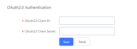
If you already have an OAuth2.0 project set up on the Google Developers web page, please use your existing login credentials for “OAuth2.0 Client ID” and “OAuth2.0 Client Secret” in the above figure for the PBX to access Google Service.
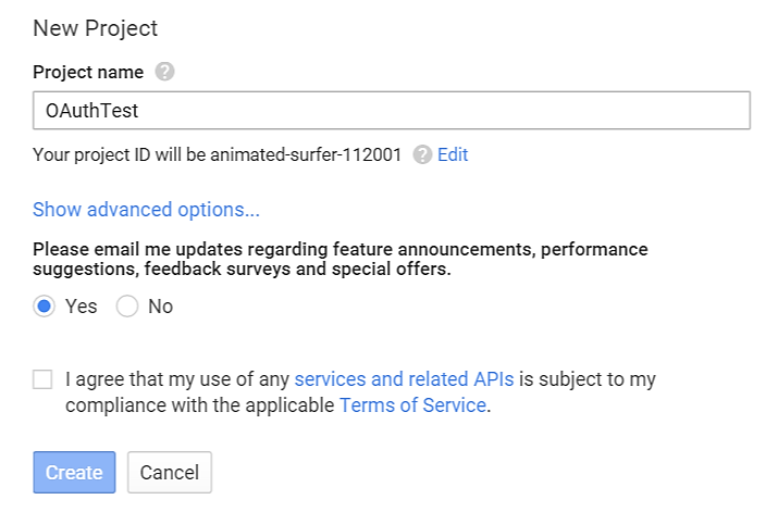
If you do not have the OAuth2.0 project set up yet, please follow the steps below to create a new project and obtain credentials:
- Go to the Google Developers page https://console.developers.google.com/start Create a New Project on the Google Developers page.
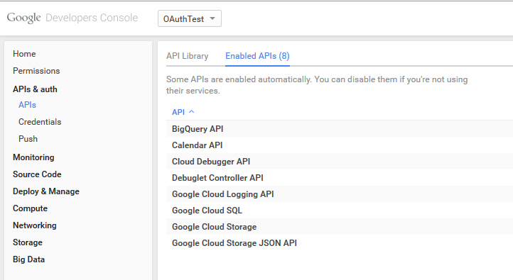
- Enable Calendar API from API Library.
- Click “Credentials” on the left drop-down menu to create new OAuth2.0 login credentials.
- Use the newly created login credential to fill in “OAuth2.0 Client ID” and “OAuth2.0 Client Secret”.
- Click “Get Authentication Code” to obtain an authentication code from Google Service.
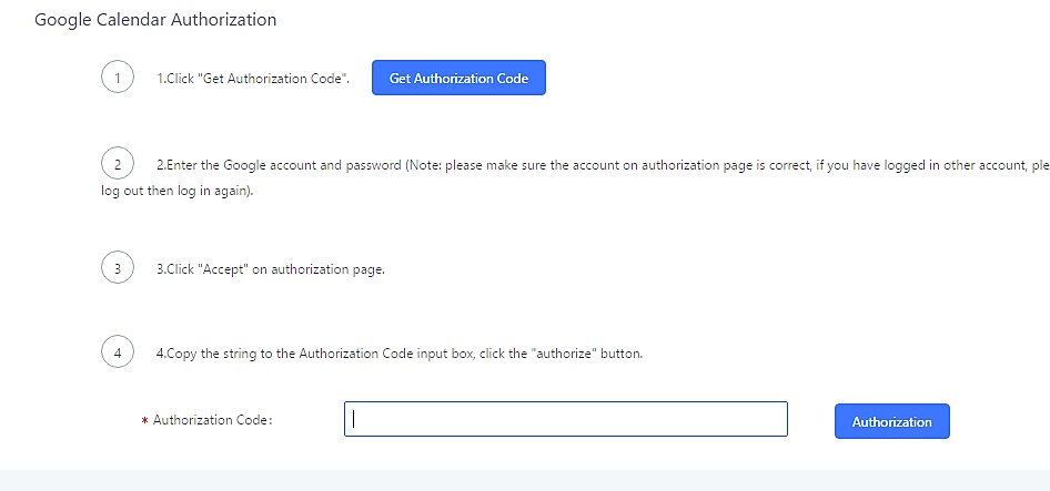
- Once this has been done, the PBX will connect to Google services.
You can also configure the Status update, which automatically refreshes your Google Calendar with the configured time (m). Note: Zero means disable.
Meeting Schedule
Log in to the IPPBX Web GUI, open the Call Features 🡪 Multimedia Meeting 🡪 Meeting Schedule page, and you can manage the reservation management of the meeting room. Users can create, edit, view, and delete conference room reservation records. The following is a set meeting room reservation, which shows the ongoing and pending reservations. Once the conference room is reserved, all users will be removed from the conference room at the start time, and extensions will no longer be allowed to enter the conference room. At the scheduled meeting time, IPPBX will send invitations to the extensions that have been selected to participate in the meeting. At the same time, it supports users to enter the meeting 10 minutes in advance. If the current meeting is occupied, enter the waiting room and wait (members joining the meeting in advance occupy global member resources, but it will be released after the scheduled meeting starts); otherwise, you can join the meeting directly and the meeting will be held in advance. After the meeting ends, the reservation record is transferred to the historical meeting list. History meeting displays the information of the ended and expired meetings.
- Click the button “Schedule Meeting” to edit the meeting room reservation.
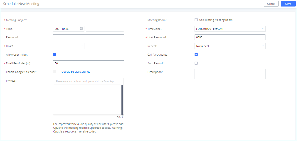
Once the Meeting Schedule is configured, the scheduled meeting will be displayed as the below figure.
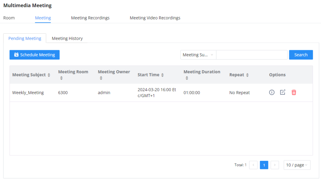
- Click the button to view the meeting details in the Meeting room. The meeting details of Meeting History include actual participant information.
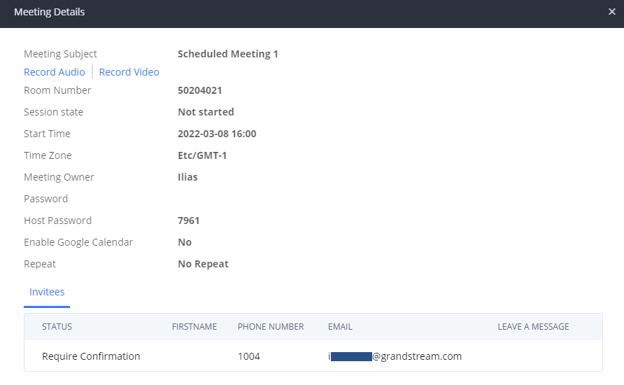
- Click on to edit the Meeting Schedule.
- Click on to delete the Meeting Schedule.
At the scheduled meeting time, PBX will send INVITE to the extensions that have been selected for the conference.
Once the meeting starts, it will be displayed under Pending Meeting with an “Ongoing” status, as displayed below:
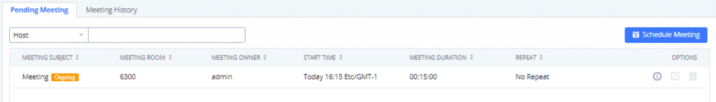
Once the conference is finished, the conference will be displayed under Historical Meeting as below:
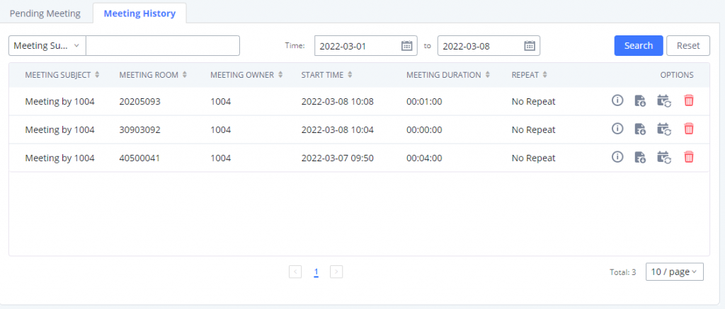
- Click the button
 to download the Meeting Report of the meeting.
 - Click the button
 to reschedule the Meeting.
In addition, once the meeting ends, the system will send a meeting report email to the host including PDF file where he/she can view the meeting, participant information, device type and trend graph of participant levels.
You can also choose to display the meetings that took place in a specific time frame. Please see the screenshot below:
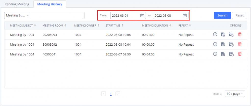
Meeting Recordings
The PBX allows users to record the audio of the meeting call and retrieve the recording from Web GUI🡪Call Features🡪 Multimedia Meeting🡪 Meeting Recordings.
To record the Meeting call, when the meeting room is idle, enable “Auto Record” from the meeting room configuration dialog. Save the setting and apply the change. When the meeting call starts, the call will be automatically recorded in .wav format.
The recording files will be listed below once available. Users could click on ![]() to download the recording or click on
to download the recording or click on ![]() to delete the recording. Users could also delete all recording files by clicking on “Delete All Recording Files” or delete multiple recording files at once by clicking on “Delete” after selecting the recording files.
to delete the recording. Users could also delete all recording files by clicking on “Delete All Recording Files” or delete multiple recording files at once by clicking on “Delete” after selecting the recording files.
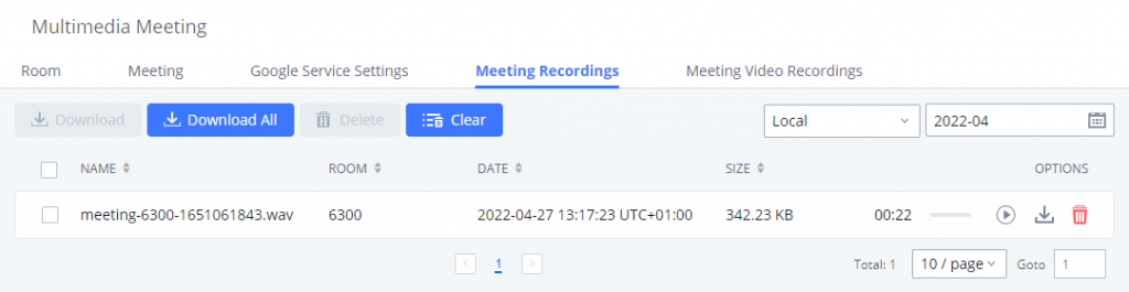
Meeting Video Recordings
The PBX allows users to record the audio and video of the meeting call and retrieve the recording from Web GUI🡪Call Features🡪 Multimedia Meeting🡪 Meeting Recordings.
To record the Meeting call, when the meeting room is idle, enable “Auto Record” from the meeting room configuration dialog. Save the setting and apply the change. When the meeting call starts, the call will be automatically recorded in .mkv format.
The recording files will be listed below once available. Users could click on ![]() to download the recording or click on
to download the recording or click on ![]() to delete the recording. Users could also delete all recording files by clicking on “Delete All Recording Files” or delete multiple recording files at once by clicking on “Delete” after selecting the recording files.
to delete the recording. Users could also delete all recording files by clicking on “Delete All Recording Files” or delete multiple recording files at once by clicking on “Delete” after selecting the recording files.
Call Statistics
Meeting reports will now be generated after every conference. These reports can be exported to a .CSV file for offline viewing. The conference report page can be accessed by clicking on the Call Statistics button on the main Conference page.
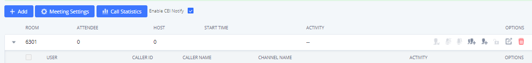
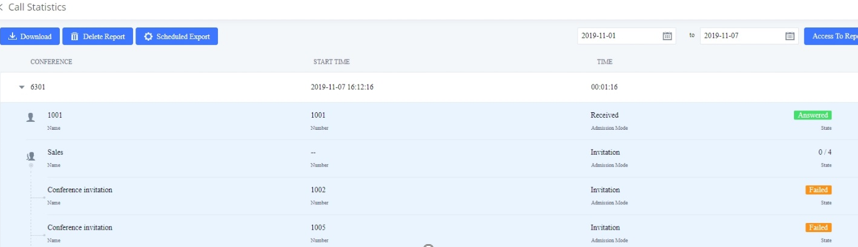
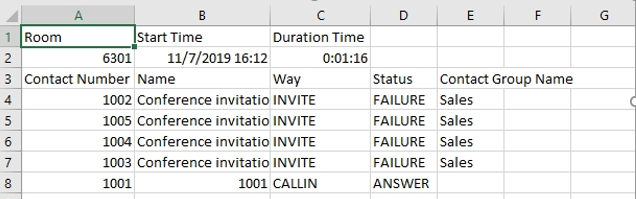
IVR
Configure IVR
IVR configurations can be accessed under the PBX Web GUI🡪Call Features🡪IVR. Users could create, edit, view, and delete an IVR.
- Click on “Add” to add a new IVR.
- Click on to edit the IVR configuration.
- Click on to delete the IVR.
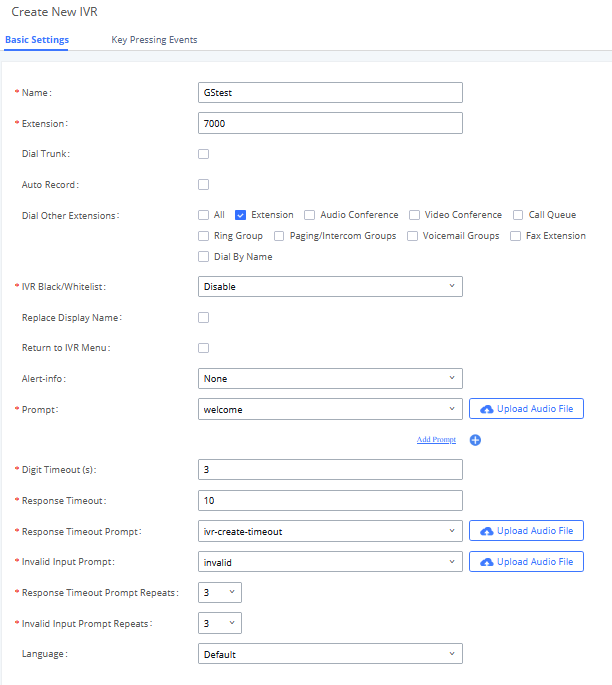
Basic Settings | |
Name | Configure the name of the IVR. Letters, digits, _ and – are allowed. |
Extension | Enter the extension number for users to access the IVR. |
Dial Trunk | If enabled, all callers to the IVR can use the trunk. The permission must be configured for the users to use the trunk first. The default setting is “No”. |
Auto Record | If enabled, calls to this IVR will automatically be recorded. |
Permission | Assign permission level for outbound calls if “Dial Trunk” is enabled. The available permissions are “Internal”, “Local”, “National” and “International” from the lowest level to the highest level. The default setting is “Internal”. If the user tries to dial outbound calls after dialing into the IVR, the PBX will compare the IVR’s permission level with the outbound route’s privilege level. If the IVR’s permission level is higher than (or equal to) the outbound route’s privilege level, the call will be allowed to go through. |
Dial Other Extensions | This controls the destination that can be reached by the external caller via the inbound route. The available destinations are:
|
IVR Black/Whitelist | If enabled only numbers inside of the Whitelist or outside of the Blacklist can be called from IVR. |
Internal Black/Whitelist | Contain numbers, either of Blacklist or Whitelist. |
External Black/Whitelist | This feature can be used only when Dial Trunk is enabled, it contains external numbers allowed or denied calling from the IVR, the allowed format is the following: Number1, number2, number3… |
Replace Display Name | If enabled, the PBX will replace the caller display name with the IVR name. |
Return to IVR Menu | If enabled and if a call to an extension fails, the caller will be redirected to the IVR menu. |
When present in an INVITE request, the alert-Info header field specifies an alternative ring tone to the UAS. | |
Prompt | Select an audio file to play as the welcome prompt for the IVR. Click on “Prompt” to add an additional audio file under Web GUI🡪PBX Settings🡪Voice Prompt🡪Custom Prompt. |
Digit Timeout | Configure the timeout between digit entries. After the user enters a digit, the user needs to enter the next digit within the timeout. If no digit is detected within the timeout, the PBX will consider the entries complete. The default timeout is 3s. |
Response Timeout | After playing the prompts in the IVR, the PBX will wait for the DTMF entry within the timeout (in seconds). If no DTMF entry is detected within the timeout, a timeout prompt will be played. The default setting is 10 seconds. |
Response Timeout Prompt | Select the prompt message to be played when the timeout occurs. |
Invalid Input Prompt | Select the prompt message to be played when an invalid extension is pressed. |
Response Timeout Prompt Repeats | Configure the number of times to repeat the prompt if no DTMF input is detected. When the loop ends, it will go to the timeout destination if configured, or hang up. The default setting is 3. |
Invalid Input Prompt Repeats | Configure the number of times to repeat the prompt if the DTMF input is invalid. When the loop ends, it will go to the invalid destination if configured, or hang up. The default setting is 3. |
Language | Select the voice prompt language to be used for this IVR. The default setting is “Default” which is the selected voice prompt language under Web GUI🡪PBX Settings🡪Voice Prompt🡪Language Settings. The dropdown list shows all the currently available voice prompt languages on the PBX. To add more languages in the list, please download the voice prompt package by selecting “Check Prompt List” under Web GUI🡪PBX Settings🡪Voice Prompt🡪Language Settings. |
Key Pressing Events | |
Press 0 Press 1 Press 2 Press 3 Press 4 Press 5 Press 6 Press 7 Press 8 Press 9 Press * | Select the event for each key pressing for 0-9, *, Timeout, and Invalid. The event options are:
For each key event, time conditions can be configured. At the configured time condition, this IVR key event can be triggered. Office time, holiday time, or specific time can be configured for time conditions. Up to 5 time conditions can be added for each key. The available time conditions are ‘All’, ‘Office Time’, ‘Out of Office Time’, ‘Holiday’, ‘Out of Holiday’, ‘Out of Office Time or Holiday’, ‘Office Time and Out of Holiday’, and ‘Specific Time’. If ‘Specific Time’ is selected, a new window will prompt for admin to configure start time, end time, and frequency. |
Timeout | When exceeding the number of defined answer timeout, IVR will enter the configured event when timeout. If not configured, then it will hang up. |
Invalid | Configure the destination when the Invalid Repeat Loop is done. |
Time Condition | Configure the time condition for each key press event, so that it goes to the corresponding destination within a specified time. |
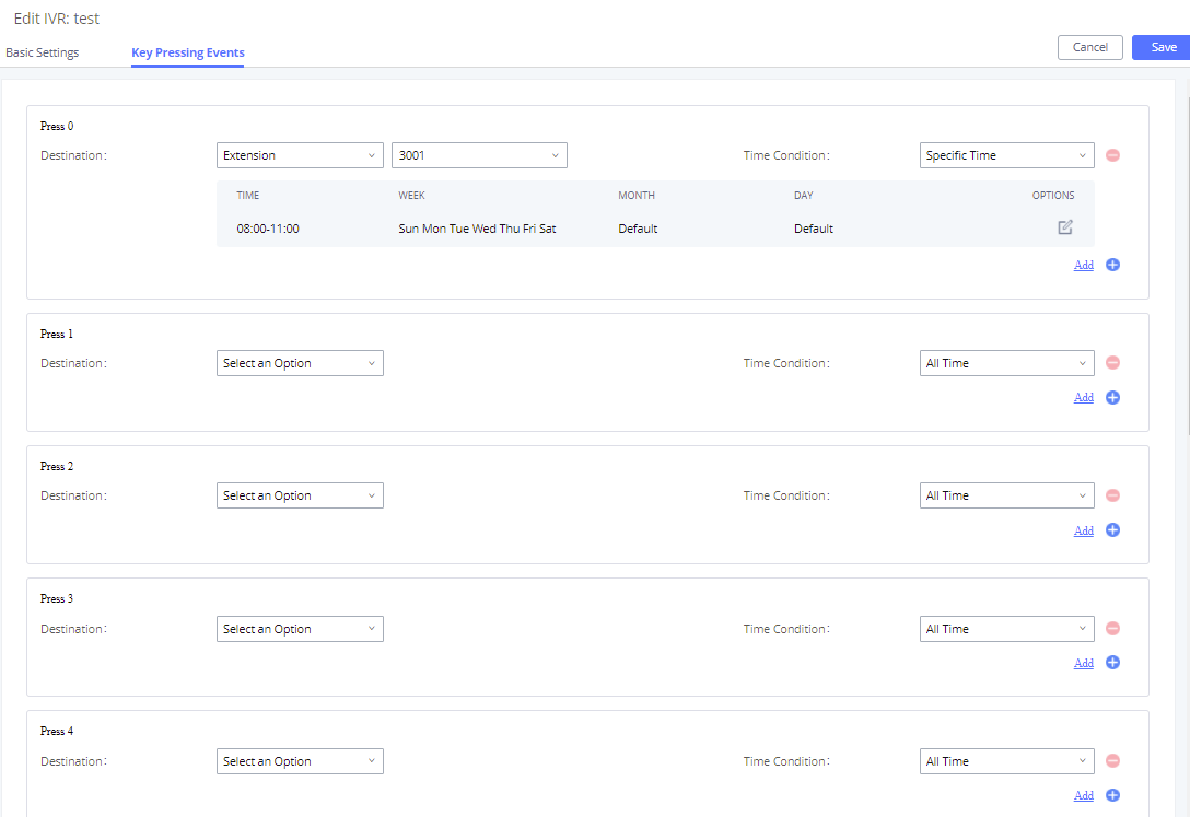
Black/Whitelist in IVR
In some scenarios, the IPPBX administrator needs to restrict the extensions that can be reached from IVR.
For example, the company CEO and directors prefer only receiving calls transferred by the secretary, and some special extensions are used on IP surveillance endpoints which should not be reached from external calls via IVR for privacy reasons. The PBX has now added blacklist and whitelist in IVR settings for users to manage this.
To use this feature, log into the PBX Web GUI and navigate to Call Features🡪IVR🡪Create/Edit IVR: IVR Black/Whitelist.
- If the user selects “Blacklist Enable” and adds an extension to the list, the extensions in the list will not be allowed to be reached via IVR.
- If the user selects “Whitelist Enable” and adds an extension to the list, only the extensions in the list can be allowed to be reached via IVR.
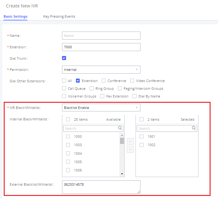
Create Custom Prompt
To record a new IVR prompt or upload IVR prompt to be used in IVR, click on “Upload Audio File” next to the “Welcome Prompt” option and the users will be redirected to the Custom Prompt page. Or users could go to Web GUI🡪PBX Settings🡪Voice Prompt🡪Custom Prompt page directly.
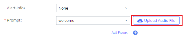
Once the IVR prompt file is successfully added to the PBX, it will be added to the prompt list options for users to select in different IVR scenarios.
Key Pressing Events
Standard Key Event
The PBX supports adding time conditions for different key events so that each key event of the IVR goes to the corresponding destination within a specified time.
Each key event supports up to five time conditions, the options available are: All time, Office Time, Out of Office Time, Holiday, Out of Holiday, Out of Office Time or Holiday, Office Time and Out Of Holiday, Specific time.
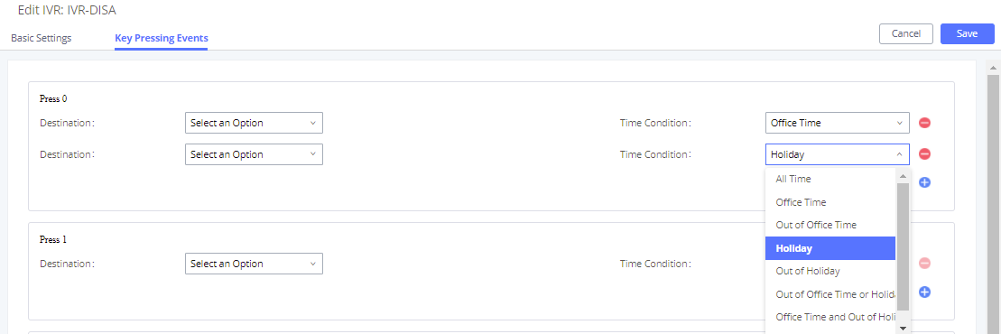
Note:
If you select “Specific time”, you need to select the start time and the end time.
The frequency supports two options: By week and By Month, by default, the specific time does not include the holidays.
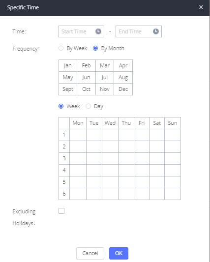
Custom Key Event
Users can create custom IVR key press events, vastly increasing the options a business can provide to its customers and improving customer relations and accessibility.
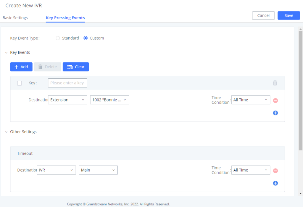
This new feature supports the following:
- Up to 100 custom key press events
- Each key combination can contain up to 8 characters (numbers and star (*) only)
- Supports Time Conditions
- Different custom keys can have the same Destination and Time Condition
Voicemail
Configure Voicemail
If the voicemail is enabled for PBX extensions, the configurations of the voicemail can be globally set up and managed under Web GUI🡪Call Features🡪Voicemail.
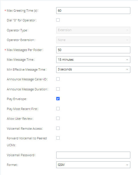
Max Greeting Time (s) | Configure the maximum number of seconds for the voicemail greeting. The default setting is 60 seconds. |
Dial ‘0’ For Operator | If enabled, the caller can press 0 to exit the voicemail application and connect to the configured operator’s extension. |
Operator Type | Configure the operator type; either an extension or a ring group. |
Operator Extension | Select the operator extension, which will be dialed when users press 0 to exit the voicemail application. The operator extension can also be used in IVR. |
Max Messages Per Folder | Configure the maximum number of messages per folder in users’ voicemail. The valid range is 10 to 1000. The default setting is 50. |
Max Message Time | Select the maximum duration of the voicemail message. The message will not be recorded if the duration exceeds the maximum message time. The default setting is 15 minutes. The available options are:
|
Min Effective Message Time | Configure the minimum duration (in seconds) of a voicemail message. Messages will be automatically deleted if the duration is shorter than the Min Message Time. The default setting is 3 seconds. The available options are:
Note: Silence and noise duration are not counted in message time. |
Announce Message Caller-ID | If enabled, the caller ID of the user who has left the message will be announced at the beginning of the voicemail message. The default setting is “No”. |
Announce Message Duration | If enabled, the message duration will be announced at the beginning of the voicemail message. The default setting is “No”. |
Play Envelope | If enabled, a brief introduction (received time, received from, etc.) of each message will be played when accessed from the voicemail application. The default setting is “Yes”. |
Play Most Recent First | If enabled, it will play the most recent message first. |
Allow User Review | If enabled, users can review the message following the IVR before sending. |
If enabled, external callers routed by DID and reaching VM will be prompted by the PBX with 2 options:
To leave a message for the extension reached by DID.
This will allow the caller to access any extension VM after entering the extension number and its VM password. Note: This option applies to inbound calls routed by DID only. The default setting is “Disabled”. | |
Enables the forwarding of voicemail to remote extensions on peered SIP trunks. The default setting is “Disabled”. | |
Configures the default voicemail password that will be used when an extension is reset. | |
Format | Warning: WAV files take up significantly more storage space than GSM files. |
Access Voicemail
If the voicemail is enabled for PBX extensions, the users can dial the voicemail access number (by default *97) to access their extension’s voicemail. The users will be prompted to enter the voicemail password and then can enter digits from the phone keypad to navigate in the IVR menu for different options.
Otherwise, the user can dial the voicemail access code (by default *98) followed by the extension number and password to access that specific extension’s voicemail.
Leaving Voicemail
If an extension has voicemail enabled under basic settings “Extension/Trunk 🡪 Extensions 🡪 Basic Settings” and after a ring timeout or the user is not available, the caller will be automatically redirected to the voicemail to leave a message on which case they can press # to submit the message.
In case the caller is calling from an internal extension, they will be directly forwarded to the extension’s voicemail box. But if the caller is calling from outside the system and the incoming call is routed by DID to the destination extension, then the caller will be prompted with the choice to either press 1 to access voicemail management or press 2 to leave a message for the called extension. This feature could be useful for remote voicemail administration.
Voicemail Email Settings
The PBX can be configured to send the voicemail as an attachment to the Email. Click on the “Voicemail Email Settings” button to configure the Email attributes and content.
Send Voicemail to Email | If enabled, voicemail will be sent to the user’s email address. Note: SMTP server must be configured to use this option. |
Keep Voicemail after Emailing | Enable this option if you want to keep recording files after the Email is sent. The default setting is Enable. |
Email Template | Fill in the “Subject:” and “Message:” content, to be used in the Email when sending to the user. The template variables are:
|
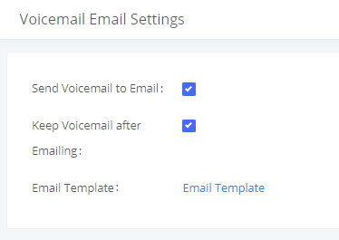
Click on the “Email Template” button to view the default template as an example.
Configure Voicemail Group
The PBX supports voicemail group and all the extensions added in the group will receive the voicemail to the group extension. The voicemail group can be configured under Web GUI 🡪 Call Features 🡪 Voicemail 🡪 Voicemail Group. Click on “Add” to configure the group.
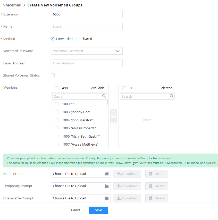
Ring Groups
The PBX supports ring group feature with different ring strategies applied to the ring group members. This section describes the ring group configuration on the PBX.
Configure Ring Group
Ring group settings can be accessed via Web GUI🡪Call Features🡪Ring Group.
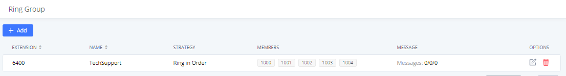
- Click on to add ring group.
- Click on to edit the ring group. The following table shows the ring group configuration parameters.
- Click on to delete the ring group.
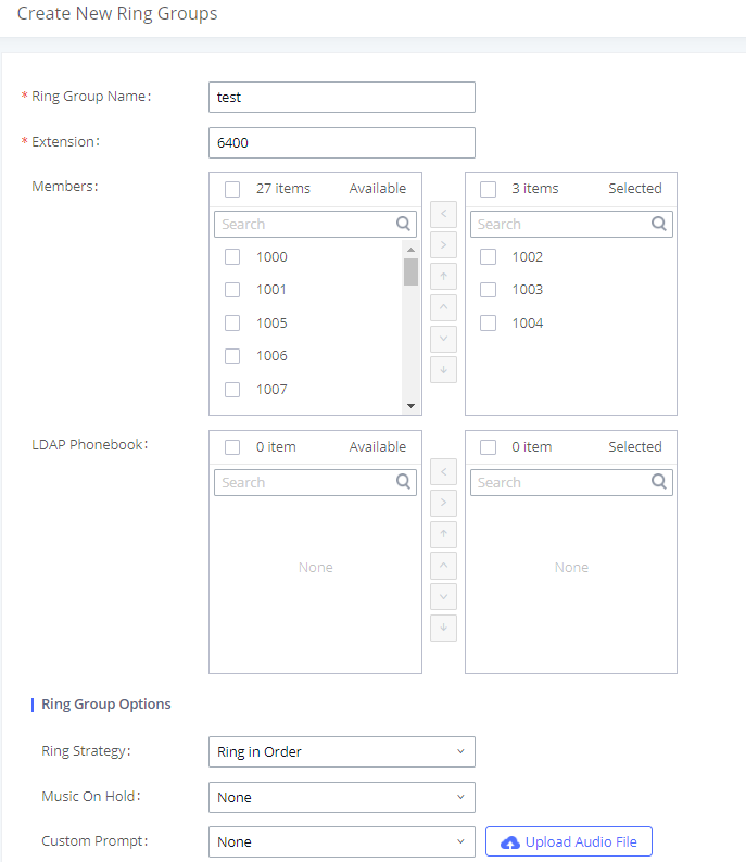
Remote Extension in Ring Group
Remote extensions from the peer trunk of a remote IPPBX can be included in the ring group with local extension. An example of Ring Group with peer extensions is presented in the following:
- Creating SIP Peer Trunk between both IPPBX_A and IPPBX_B. SIP Trunk can be found under Web GUI🡪Extension/Trunk🡪VoIP Trunks. Also, please configure their Inbound/Outbound routes accordingly.
- Click edit button in the menu , and check if Sync LDAP Enable is selected, this option will allow IPPBX_A update remote LDAP server automatically from peer IPPBX_B. In addition, Sync LDAP Password must match for IPPBX_A and IPPBX_B to sync LDAP contact automatically. Port number can be anything between 0~65535, and use the outbound rule created in step 1 for the LDAP Outbound Rule option.
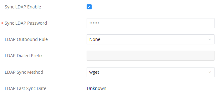
- In case if LDAP server does not sync automatically, user can manually sync LDAP server. Under VoIP Trunks page, click sync button shown in the following figure to manually sync LDAP contacts from peer IPPBX.
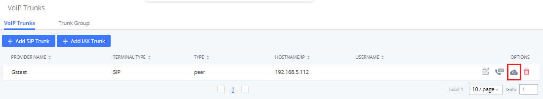
- Under Ring Groups setting page, click “Add”. Ring Groups can be found under Web GUI🡪Call Features🡪Ring Groups.
- If LDAP server is synced correctly, Available LDAP Numbers box will display available remote extensions that can be included in the current ring group. Please also make sure the extensions in the peer IPPBX can be included into that IPPBX’s LDAP contact.
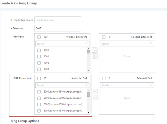
Restrict Calls
Restrict calls is a feature that can be used to restrict calls between internal extensions besides those in the Allowed List.
This section describes the configuration of this feature in the Call Features->Restrict Calls page.
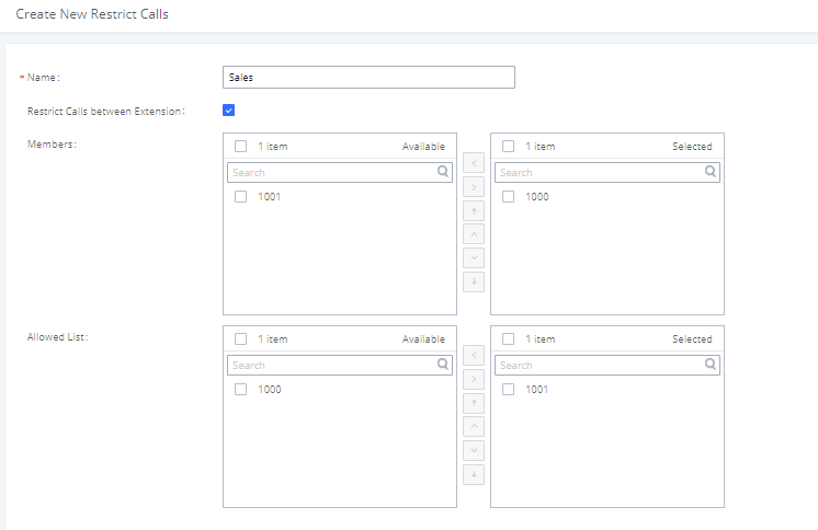
Configure Restrict Calls
- Click on “Add” to add a rule for restrict calls.
- Click on to edit the rule of restrict calls.
- Click on to delete the rule of restrict calls.
Name | Configure Restrict call’s name |
Restrict Calls between extensions | When enabled, members of the group cannot dial other extension, only the numbers in the Allowed List. By default it’s enabled. |
Members | Configure the members that will not be able to call any extensions besides those in the Allowed List. |
Allowed list | Select the extensions that the Members list can be able to call. |
Paging/Intercom
Paging and Intercom Group can be used to make an announcement over the speaker on a group of phones. Targeted phones will answer immediately using speaker. The IPPBX paging and intercom can be used via feature code to a single extension or a paging/intercom group. This section describes the configuration of paging/intercom group under Web GUI🡪Call Features🡪Paging/Intercom.
Paging/Intercom Groups
2-way Intercom
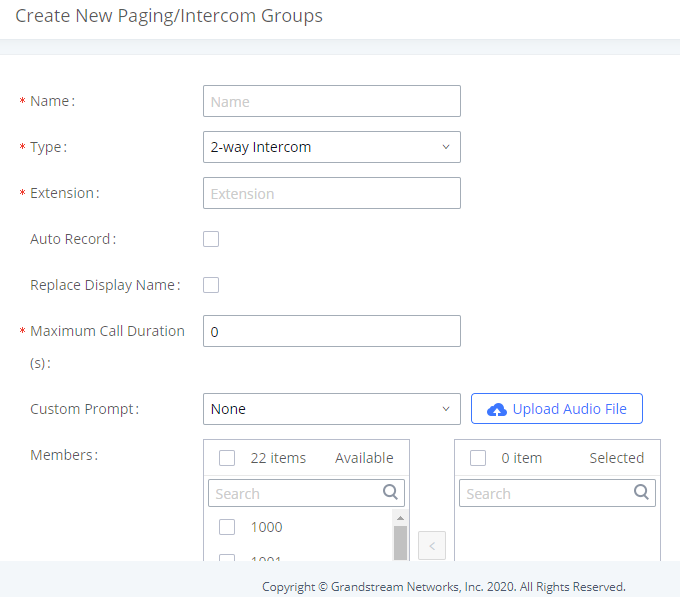
Name | Configure paging/intercom group name. |
Type | Select “2-way Intercom”. |
Extension | Configure the paging/intercom group extension. |
Auto Record | Enable this option to record in WAV format. |
Replace Display Name | If enabled, the IPPBX will replace the caller display name with Paging/Intercom name. |
Maximum Call Duration | Specify the maximum call duration in seconds. The default value 0 means no limit. |
Custom Prompt | This option is to set a custom prompt for a paging/intercom group to announce to caller. Click on ‘Prompt’, it will direct the users to upload the customized voice prompts. Note: Users can also refer to the page PBX Settings🡪Voice Prompt🡪Custom Prompt, where they could record new prompt or upload prompt files. |
Members | Select available users from the left side to the paging/intercom group member list on the right. |
Paging/Intercom Whitelist | Select which extensions are allowed to use the paging/intercom feature for this paging group. |
1-way Paging
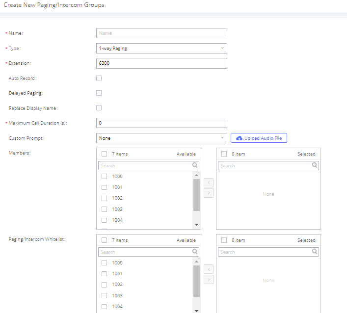
| Name | Configure paging/intercom group name. |
| Type | Select “1-way Paging”. |
| Extension | Configure the paging/intercom group extension. |
| Video Broadcast | If checked, video paging will be supported. If the caller sends a video page, the paging group members will be able to receive and view the video. |
| Auto Record | Enable this option to record in WAV format. |
| Delayed Paging | Allows the announcement to be played after the configured delay paging. If there are many messages, they will be played in sequence. |
| LaggedTime(seconds) | Set the delay paging duration, the default is 5 seconds. |
| Replace Display Name | If enabled, the IPPBX will replace the caller display name with Paging/Intercom name. |
| Maximum Call Duration | Specify the maximum call duration in seconds. The default value 0 means no limit. |
| Custom Prompt | This option is to set a custom prompt for a paging/intercom group to announce to caller. Click on ‘Prompt’, it will direct the users to upload the customized voice prompts.Note: Users can also refer to the page PBX Settings🡪Voice Prompt🡪Custom Prompt, where they could record new prompt or upload prompt files. |
| Members | Select available users from the left side to the paging/intercom group member list on the right. |
| Paging/Intercom Whitelist | Select which extensions are allowed to use the paging/intercom feature for this paging group. |
In case the user wants to broadcast a video, these requirements should be respected.
- H.264 video encoding
- .mkv or .tar/.tgz/tar.gz format
- MKV files must be 30 MB file or less
- Compressed files (.tar/.tgz/tar.gz) must be 50 MB or less.
- File name can only contain alphanumeric characters, hyphens (-) and period (.)
If Auto Record is enabled, recorded video pages will be saved in MKV file format.Saved recordings can be found in the CDR🡪Recordings🡪Video Recordings page.
Multicast Paging
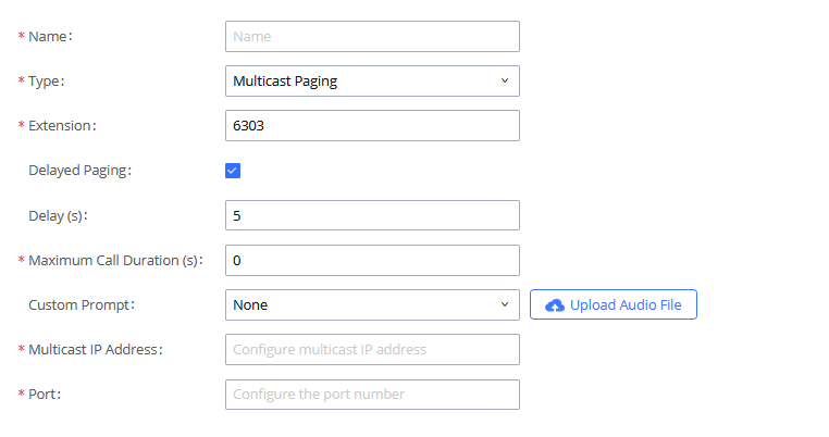
Name | Configure paging/intercom group name. |
Strategy | Select “Multicast Paging”. |
Extension | Configure the paging/intercom group extension. |
Delayed Paging | If enabled, a caller can enter *82 before the paging group extension to start a delayed paging call. In a delayed paging call, the system will prompt the caller to record a message. Once the messaging is recorded and saved, and the configured delay has passed, the paging call will be sent out. When a paging group member answers the call, the recorded message will be played, and the call will end after it is finished playing. |
Delay (s) | Configure the amount of delay in seconds after a message is recorded to send out the delayed paging call. Default is 5 seconds. |
Maximum Call Duration | Specify the maximum call duration in seconds. The default value 0 means no limit. |
Custom Prompt | This option is to set a custom prompt for a paging/intercom group to announce to caller. Click on ‘Prompt’, it will direct the users to upload the customized voice prompts. Note: Users can also refer to the page PBX Settings🡪Voice Prompt🡪Custom Prompt, where they could record new prompt or upload prompt files. |
Play Prompt to Caller | Play the prompt to the caller. |
Prompt Playback Count | Sets the number of times the prompt is played during the page/intercom. To ensure the prompt is played the specified number of times, please set an appropriate max call duration. |
Multicast IP Address/Port | The allowed multicast IP address range is 224.0.1.0 – 238.255.255.255. Note: You can add up to 30 multicast addresses. |
Paging/Intercom Whitelist | Select the extension which can initiate this paging. If none is selected, all extensions will be able to use this paging/intercom group. |
Multicast Community
Multicast community allows creating an extension, which when dialed, can send a preconfigured prompt as a multicast paging to a group of extensions. The user should create first a Paging/Intercom Group with Multicast Paging as the Strategy selected. Please see previous section for more information.
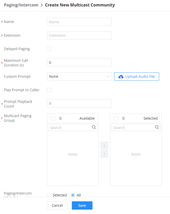
Name | Enter the name of the multicast community. |
Extension | Configure the extension number for the paging/intercom group. When this number is dialed, the paging/intercom will be initiated. |
Delayed Paging | If enabled, a caller can enter *82 before the paging group extension to start a delayed paging call. In a delayed paging call, the system will prompt the caller to record a message. Once the messaging is recorded and saved, and the configured delay has passed, the paging call will be sent out. When a paging group member answers the call, the precorded message will be played, and the call will end after it is finished playing.
|
Maximum Call Duration (s) | The maximum allowed duration of a call in seconds. Default value is 0 (no limit). Note: Please note that the call duration that can be configured can be within the range 0 - 86400. |
Custom Prompt | Choose the custom prompt to play for the callees at the beginning of the paging. The user can also directly upload a prompt file directly on this page. Note: When uploading the custom prompt file, please make sure it respects the following requirements:
|
Play Prompt to Caller | When this option is enabled, the prompt will be played back on the caller's phone. |
Prompt Playback Count | Sets the number of times the prompt is played during the page/intercom. To ensure the prompt is played the specified number of times, please set an appropriate max call duration. Note: The minimum number of playcounts which can be configured is 1 and the maximum is 10. |
Multicast Paging Group | Configures multicast paging groups within a community. When dialing the extension number of the community, users may simultaneously initiate paging to linked multicast paging groups. |
Paging/Intercom Whitelist |
|
Scheduled Paging/Intercom
Pending Paging/Intercom
In this page, the user can create scheduled intercom/paging to be played automatically when the time scheduled arrives.
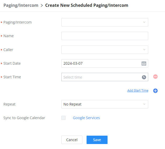
Paging/Intercom | Select existing paging/intercom groups and multicast communities. |
Name | Enter the name of the scheduled Intercom/Paging. |
Caller | Once a caller is selected, and the specified start time is reached, the system will contact the caller. If this call is rejected, the page/intercom will be cancelled. If caller is set to None, the system will call all group members and play the configured prompt. |
Start Date | Select the date of the start of the paging/intercom. |
Start Time | Select the start time of the paging/intercom. |
Repeat | Select the repeat interval of the paging/intercom.
|
Include Holidays | When Every day, Weekly, or Monthly is selected. This option will appear. If enabled, scheduled pages/intercoms will run during holidays. Otherwise, scheduled pages/intercoms displayed on the calendar will not actually be run. |
Sync to Google Calendar | This feature cannot be used if Google Services have not been authorized. Please resolve this in the Integrations > Google Services page. |
Once the paging and intercom has been created, it can be viewed on the same page.
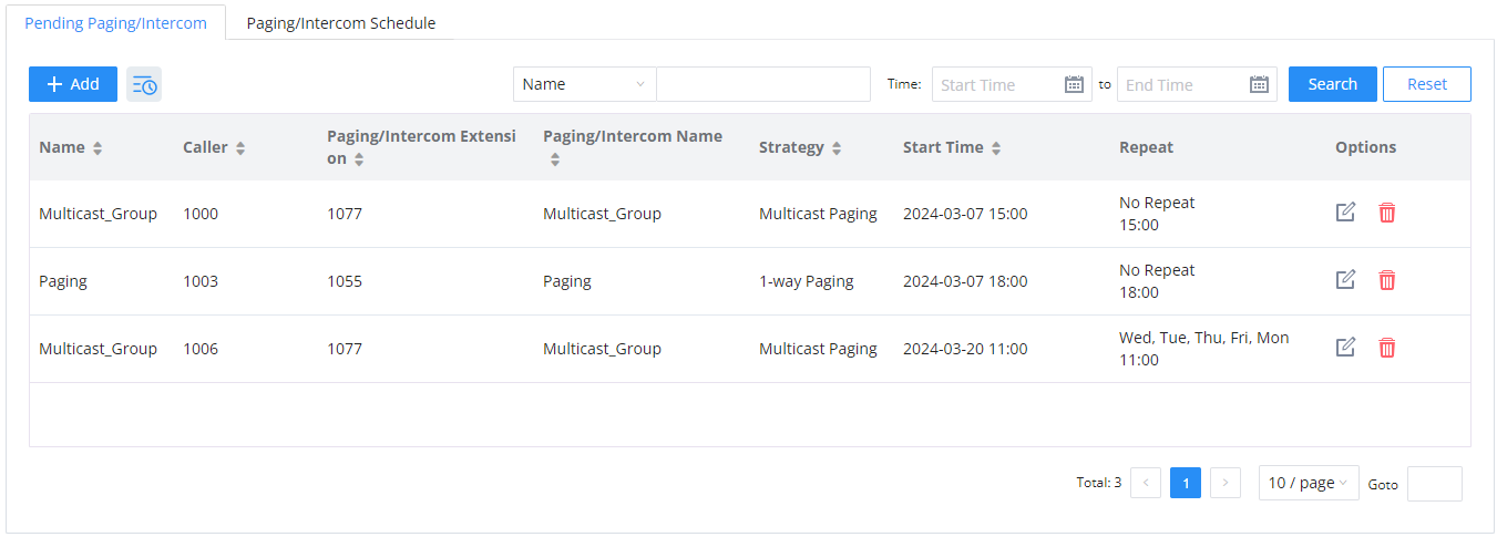
Paging/Intercom Schedule
This section displays the schedule of the paging/intercom which have been scheduled. The user can choose to display per day, week, or per month.
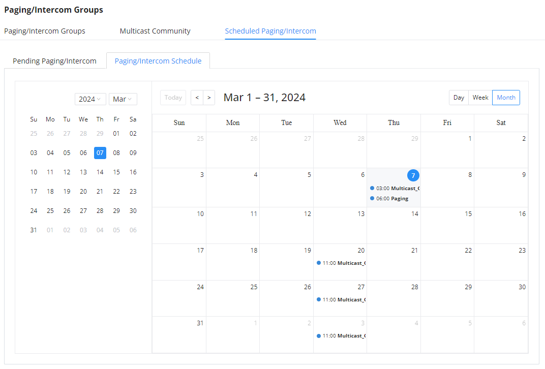
Operator Panel
Configure Operator Panel
Operator Panel settings can be accessed via Web GUI🡪Call Features🡪Operator Panel.
The PBX supports the operator panel so that IPPBX extension can be used as admin to manage calls and activities such as extension status, call queue status, transfer, barge-in, hangup, etc. On Grandstream Wave client, it can display the extensions, ring group, voicemail, call queue, call park status under the management of the extension. This section describes how to configure the operator panel.
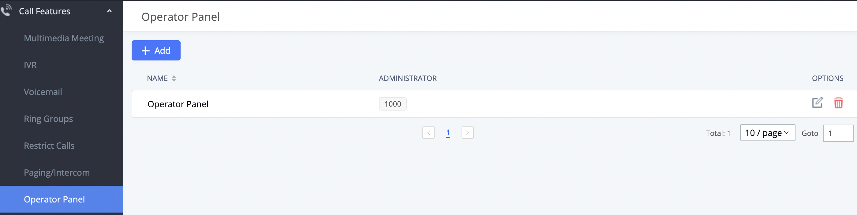
- Click on “Add” to create the operator panel.
- Click on
 to edit the operator panel.
 - Click on
 to delete the operator panel.
Call Queue
The PBX supports call queue by using static agents or dynamic agents. Call Queue system can accept more calls than the available agents. Incoming calls will be held until next representative is available in the system. This section describes the configuration of call queue under Web GUI🡪Call Features🡪Call Queue.
Configure Call Queue
Call queue settings can be accessed via Web GUI🡪Call Features🡪Call Queue.
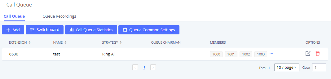
The PBX supports custom prompt feature in call queue. This custom prompt will active after the caller waits for a period of time in the Queue. Then caller could choose to leave a message/ transfer to default extension or keep waiting in the queue.
To configure this feature, please go to IPPBX Web GUI🡪Call Features🡪Call Queue🡪Create New Queue/Edit Queue🡪Queue Options🡪set Enable Destination to Enter Destination with Voice Prompt. Users could configure the wait time with Voice Prompt Cycle.
- Click on “Add” to add call queue.
- Click on to edit the call queue. The call queue configuration parameters are listed in the table below.
- Click on to delete the call queue.
Click on “Global Queue Settings” to configure Agent Login Extension Postfix and Agent Logout Extension Postfix. Once configured, users could log in the call queue as dynamic agent.
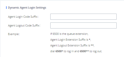
For example, if the call queue extension is 6500, Agent Login Extension Postfix is * and Agent Logout Extension Postfix is **, users could dial 6500* to login to the call queue as dynamic agent and dial 6500** to logout from the call queue. Dynamic agent does not need to be listed as static agent and can log in/log out at any time.
- Call queue feature code “Agent Pause” and “Agent Unpause” can be configured under Web GUI🡪Call Features🡪Feature Codes. The default feature code is *83 for “Agent Pause” and *84 for “Agent Unpause”.
Note: When dialing the “Agent Pause” feature code, users can specify the reason for it. The following reasons are available: (1) Lunch, (2) Hourly Break, (3) Backoffice, (4) Email, and (5) Wrap.
The agent can also dial the feature with the number of the reason of the pause. E.g., if the agent want to perform a pause for lunch, he/she can dial *831 directly instead of waiting for the IVR response.
- Queue recordings are shown on the Call Queue page under “Queue Recordings” Tab. Click on
 to download the recording file in .wav format; click on to delete the recording file. To delete multiple recording files by one click, select several recording files to be deleted and click on “Delete Selected Recording Files” or click on “Delete All Recording Files” to delete all recording files.
Call Center Settings and Enhancements
IPPBX supports light weight call center features including virtual queue and position announcement, allowing the callers to know their position on the call queue and giving them the option to either stay on the line waiting for their turn or activate a callback which will be initiated by the IPPBX one an agent is free.
To configure call center features, press ![]() on an existing call queue and go under the advanced settings tab.
on an existing call queue and go under the advanced settings tab.
Following parameters are available:
Enable Virtual Queue | Enable virtual queue to activate call center features. |
Virtual Queue Period | Configure the time in (s) after which the virtual queue will take effect and the menu will be presented to the caller to choose an option. Default is 20s. |
Virtual Queue Mode | Offered to caller after timeout: After the virtual queue period passes, the caller will enter the virtual call queue and be presented with a menu to choose an option, the choices are summarized below:
Triggered on user request: In this mode, the callers can activate the virtual queue by pressing 2, then they will be presented with the menu to choose an option as below:
|
Virtual Queue Outbound Prefix | System will add this prefix to dialed numbers when calling back users. |
Enable Virtual Queue Timeout | When this option is enabled and after a caller registers a call back request on the virtual queue. While all the agents are busy, the IPPBX will call an agent once he/she is idle again, this timeout is used for how long the IPPBX continues calling the agent and if the agent doesn’t answer the call then the callback request will timeout and expire. |
Write Timeout | Configure the virtual queue callback timeout period in seconds. |
Enable Virtual Queue Position Announcement | Enable the announcement of the caller’s position periodically. Note: Queue position will now be announced to the caller upon entering the queue. |
Position Announcement Interval | Configure the period of time in (s) during which the IPPBX will announce the caller’s position in the call queue. |
Enable Virtual Queue Wait Time Announcement | When enabled the IPPBX will announce the estimated queue wait time to callers if the estimated wait time is longer than 1 minute. |
Queue Chairman | Select the extension to act as chairman of the queue (monitoring). |
Virtual Queue Welcome Prompt | Click on “Upload Audio File” to upload the VQ welcome prompt. |
When enabled, statics agents can conveniently log in and out of a queue by configuring a programmable key on their phones as a shortcut. Notes:
|
The waiting callers are connecting with available members in a parallel fashion until there are no more available members or no more waiting callers.
For example, in a call queue with linear method, if there are two available agents, when two callers call in the queue at the same time, IPPBX will assign the two callers to each of the two available agents at the same time, rather than assigning the second caller to second available agent after the first agent answers the call from the first caller.
Call Queue Statistics
Along with call center features, users can also gather detailed call queue statistics allowing them to make better changes/decision to manage better the call distribution and handling based on time, agent, and queue.
To access call queue statistics, go to Web GUI🡪Call Features🡪Call Queue and click on “Call Queue Statistics”, the following page will be displayed:
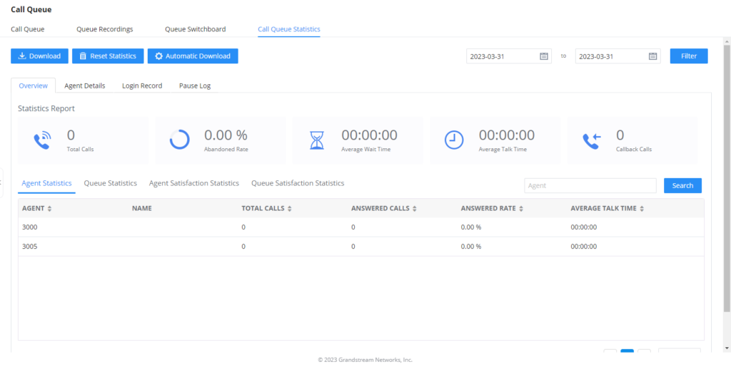
- Agent statistics: shows the number of calls and call-related information of agents;
- Queue Statistics: counts the number of calls in the queue and information such as calls, waiting, and callback;
- Agent satisfaction statistics used for user’s rating of agents;
- Queue satisfaction statistics counts the score survey statistics.
The overview page performs seat statistics, queue statistics, seat satisfaction statistics, and queue satisfaction statistics according to the business. Agent statistics record the number of calls and call-related information of agents; queue counts the number of calls in the queue and information such as calls, waiting, and callback; agent satisfaction statistics are survey statistics based on user ratings of agents; queue satisfaction statistics are user-queue The score survey statistics.
By selecting a time interval, administrators can get detailed statistics for agent(s) such as total calls, answered calls etc, as well as for the queue(s) such as ABANDONED CALLS also a detailed information for the queue’s call log by clicking on Options🡪Information button and the below window will pop up:
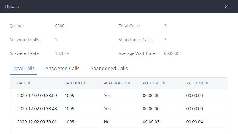
User can download statistics on CSV format by clicking on the “Download”, also the statistics can be cleared using “Reset Statistics” button.
The statistics can be automatically sent to a specific email address on a pre-configured Period, this can be done by clicking on “Automatic Download”, and user will be directed to below page where he can configure the download period (Day/Week/Month) and the Email where the statistics will be sent (Email settings should be configured correctly):
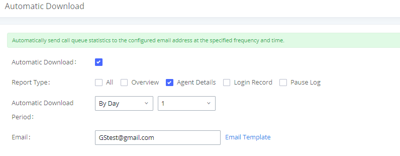
Significantly more information is now available IPPBX’s queue statistics page. In addition to the information presented in previous firmware, users can now view a call log that displays calls to all agents and queues, a dynamic agent login/logout record, and a pause log. Statistics reports for these new pages can be obtained by pressing the Download button in the top left corner of the Call Queue Statistics page. The reports are in .CSV format and will be packaged into a single tar.gz file upon download.
Agent Details is a call log that shows every call to each individual agent from all queues. The following information is available:
- Time – the date and time the call was received.
- Agent – the agent that was rung for the call.
- Queue – the queue that the call went to.
- Caller ID Number – the CID of the caller
- Abandoned – indicates whether the call was picked up or not by that specific agent. If the call rang several agents simultaneously, and this specific agent did not pick up the call, the call will be considered abandoned even if a different agent in the same queue picked it up.
- Wait Time – the amount of time that the call was waiting in queue after dialing in.
- Talk Time – the duration of the call after it was picked up by agent.
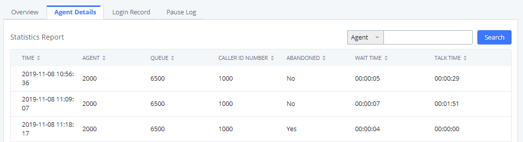
Login Record is a report that shows the timestamps of dynamic agent logins and logouts and calculates the amount of time the dynamic agents were logged in. Dynamic agents are extensions that log in and out either via agent login/logout codes (configured in Global Queue Settings page) or by using the GXP21xx call queue softkey. A new record will be created only when an agent logs out. The following information is available:
- Agent – the extension that logged in and out.
- Queue – the queue that the extension logged in and out of.
- Login Time – the time that the extension logged into the queue.
- Logout Time – the time that the extension logged out of the queue.
- Login Duration – the total length of time that the extension was logged in.
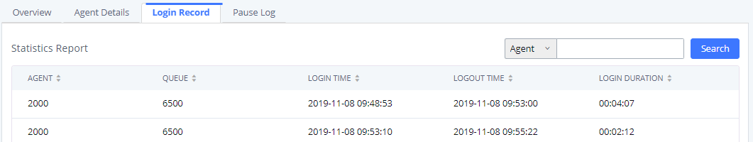
Pause Log is a report that shows the times of agent pauses and unpauses and calculates the amount of time that agents are paused. If an agent is part of several queues, an entry will be created for each queue. An entry will only be created after an agent unpauses. The following information is available:
- Agent: The extension that paused/unpaused.
- Name: The name of the agents that paused/unpaused.
- Queue: The queue that the agent is in.
- Pause Time: The time when the agent paused.
- Resume Time: The time when the agent unpaused.
- Pause Duration: The total length of time the agent was paused for.
- Pause Reason: The reason of the pause (e.g., lunch, coffee break, etc…)
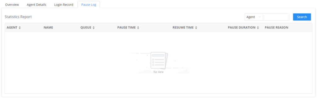
Switchboard
Switchboard is a Web GUI tool for call queue monitoring and management, admin can access to it from the menu Call Features🡪Call Queue then press “Switchboard”.
Following page will be displayed:
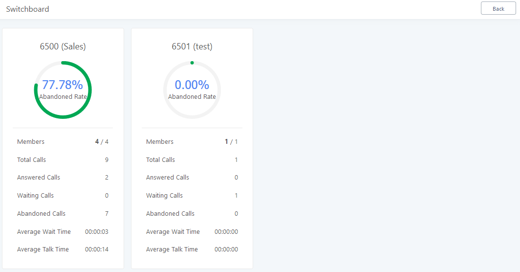
Page above summarizes the available queues statistics and if one of the queues is clicked the user will be directed to page below:
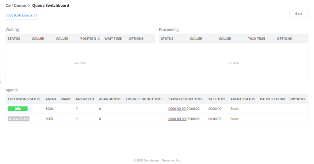
The table below gives a brief description for the main menus:
There are three different privilege levels for Call Queue management from the switchboard: Super Admin, Queue Chairman, and Queue Agent.
- Super Admin – Default admin of the IPPBX. Call queue privileges include being able to view and edit all queue agents, monitor, and execute actions for incoming and ongoing calls for each extension in Switchboard, and generate Call Queue reports to track performance.
- Queue Chairman – User appointed by Super Admin to monitor and manage an assigned queue extension via Switchboard. The Queue Chairman can log into the IPPBX user portal with his extension number and assigned user password. To access the Switchboard, click on “Other Features” in the side menu and click on “Call Queue”. In the image below, User 1001 is the Queue Chairman appointed to manage Queue Extension 6500 and can see all the agents of the queue in the Switchboard and their related information (Extension Status, Agent, Name, Answered, Abandoned, Login/Logout Time, Pause/Resume Time, Talk Time, Agent Status, Pause Reason, and Options). The Chairman is also able to log out dynamic agents from call queues.
- Queue Agent – User appointed by Super Admin to be a member of a queue extension. A queue agent can log into the IPPBX user portal with his extension number and assigned user password. To access the Switchboard, click on “Other Features” in the side menu and click on “Call Queue”. However, a queue agent can view and manage only his own calls and statistics, but not other agents’ in the queue extension. In the image below, User 1000 is a queue agent and can see only his own information in the Switchboard.
Global Queue Settings
As explained before, under this section users can configure the feature codes for Dynamic agent login and logout, and also can now customize the keys for virtual queue options like shown below.
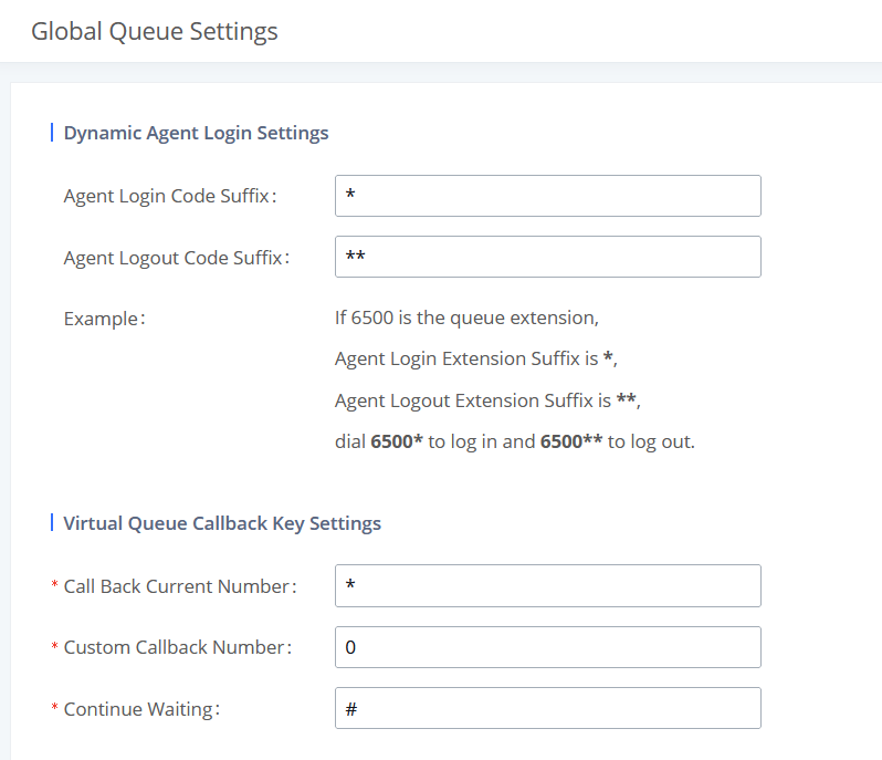
Dynamic Agent Login Settings | |
Agent Login Code Suffix |
Configure the code to dial after the queue extension to log into the queue (i.e. queue extension + suffix).
|
Agent Logout Code Suffix |
Configure the code to dial after the queue extension to log out of the queue (i.e. queue extension + suffix).
|
Enable | Select whether to enable or disable virtual queue callback feature. By default it’s disabled. |
Call Back Current Number | Press the feature key configured to set your current number as callback number. |
Custom Callback Number | Press these feature key configured to set a custom callback number. |
Continue Waiting | Press the feature key configured to continue waiting. |
Pickup Groups
The PBX supports pickup group feature which allows users to pick up incoming calls for other extensions if they are in the same pickup group, by dialing “Pickup Extension” feature code (by default *8).
Configure Pickup Groups
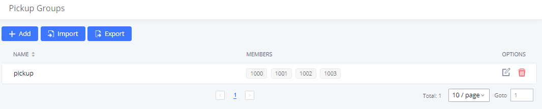
Pickup groups can be configured via Web GUI🡪Call Features🡪Pickup Groups.
- Click on to create a new pickup group.
- Click the
 button to upload the pickup group information in CSV format.
 - Click the
 button to generate pickup group information in .CSV format.
 - Click on to edit the pickup group.
- Click on to delete the pickup group.
Select extensions from the list on the left side to the right side.
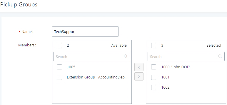
Configure Pickup Feature Code
When picking up the call for the pickup group member, the user only needs to dial the pickup feature code. It is not necessary to add the extension number after the pickup feature code. The pickup feature code is configurable under Web GUI🡪Call Features🡪Feature Codes.
The default feature code for call pickup extension is *8, otherwise if the person intending to pick up the call knows the ringing extension they can use ** followed by the extension number in order to perform the call pickup operation. The following figure shows where you can customize these features codes
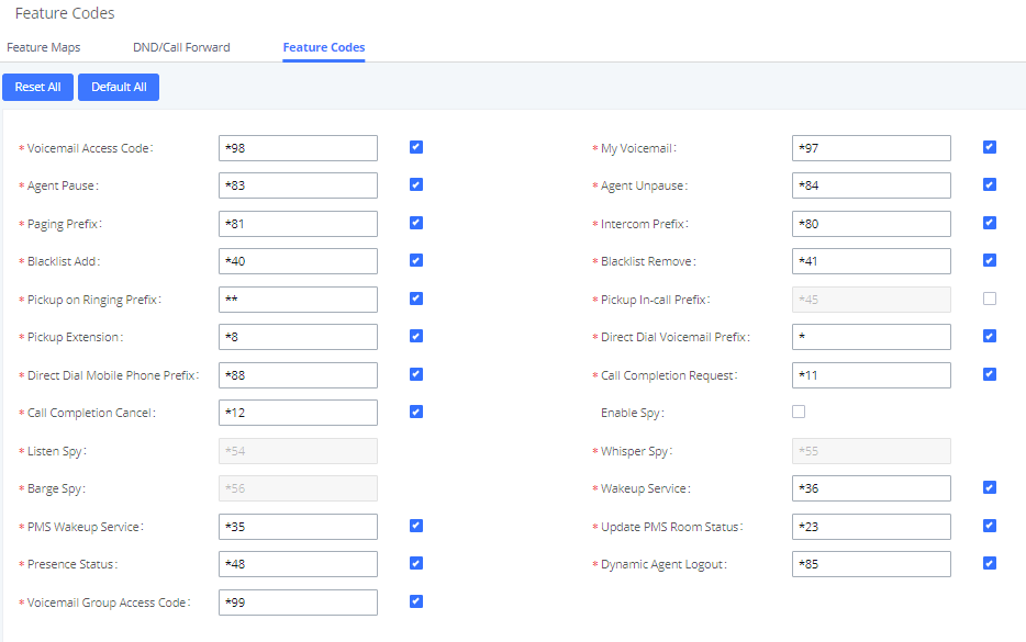
Dial By Name
Dial by Name is a feature on the PBX that allows caller to search a person by first or last name via his/her phone’s keypad. The administrator can define the Dial by Name directory including the desired extensions in the directory and the searching type by “first name” or “last name”. After dialing in, the PBX IVR/Auto Attendant will guide the caller to spell the digits to find the person in the Dial by Name directory. This feature allows customers/clients to use the guided automatic system to contact the enterprise employees without having to know the extension number, which brings convenience and improves business image for the enterprise.
Dial by Name Configuration
The administrators can create the dial by name group under Web GUI🡪Call Features🡪Dial By Name.
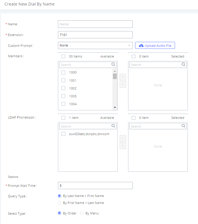
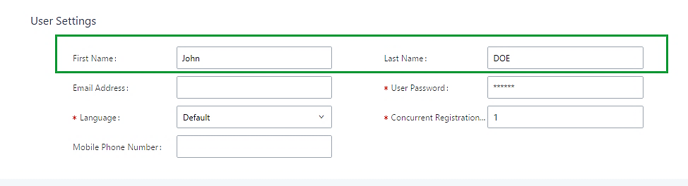
- Name
Enter a Name to identify the Dial by Name group.
- Extension
Configure the direct dial extension for the Dial By Name group.
- Custom Prompt
This option sets a custom prompt for directory to announce to a caller. The file can be uploaded from the page “Custom Prompt”. Click “Upload Audio File” to add additional record.
- Available Extensions/Selected Extensions
Select available extensions from the left side to the right side as the directory for the Dial By Name group. Only the selected extensions here can be reached by the Dial By Name IVR when dialing into this group. The extensions here must have a valid first name and last name configured under Web GUI🡪Extension/Trunk🡪Extensions in order to be searchable in Dial By Name directory through IVR. By specifying the extensions here, the administrators can make sure unscreened calls will not reach the company employee if he/she does not want to receive them directly.
- Prompt Wait Time
Configure “Prompt Wait Time” for Dial By Name feature. During Dial By Name call, the caller will need to input the first letters of First/Last name before this wait time is reached. Otherwise, timeout will occur, and the call might hang up. The timeout range is between 3 and 60 seconds.
- Query Type
Specify the query type. This defines how the caller will need to enter to search the directory.
By First Name: enter the first 3 digits of the first name to search the directory.
By Last Name: enter the first 3 digits of the last name to search the directory.
- Select Type
Specify the select type on the searching result. The IVR will confirm the name/number for the party the caller would like to reach before dialing out.
By Order: After the caller enters the digits, the IVR will announce the first matching party’s name and number. The caller can confirm and dial out if it is the destination party, or press * to listen to the next matching result if it is not the desired party to call.
By Menu: After the caller enters the digits, the IVR will announce 8 matching results. The caller can press number 1 to 8 to select and call or press 9 for results in next page.
The Dial by Name group can be used as the destination for inbound route and key pressing event for IVR. The group name defined here will show up in the destination list when configuring IVR and inbound route. If Dial by Name is set as a key pressing event for IVR, user could use ‘*’ to exit from Dial by Name, then re-enter IVR and start a new event. The following example shows how to use this option.
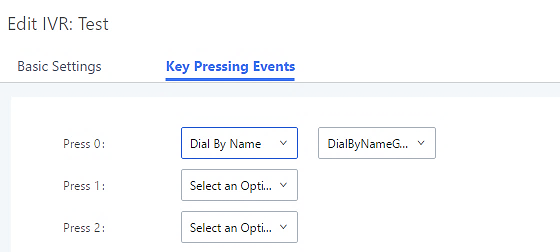

Please refer to [Username Prompt Customization] for Username Prompt Customization.
Speed Dial
Add Speed Dial
The PBX supports Speed Dial feature that allows users to call a certain destination by pressing one or four digits on the keypad. This creates a system-wide speed dial access for all the extensions on the PBX.
To enable Speed Dial, on the PBX Web GUI, go to page Web GUI🡪Call Features🡪Speed Dial.
User should first click on ![]() . Then decide from one digit up to four digits combination used for Speed Dial and select a dial destination from “Default Destination”. The supported destinations include extension, voicemail, conference room, voicemail group, IVR, ring group, call queue, page group, DISA, Dial by Name and external number.
. Then decide from one digit up to four digits combination used for Speed Dial and select a dial destination from “Default Destination”. The supported destinations include extension, voicemail, conference room, voicemail group, IVR, ring group, call queue, page group, DISA, Dial by Name and external number.
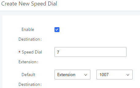

Import Speed Dial
The user can import speed dial entries from a csv file, this reduces the amount of configuring the same speed dial entries on different IPPBXs. To do this, please click on “Import” as the figure below shows.
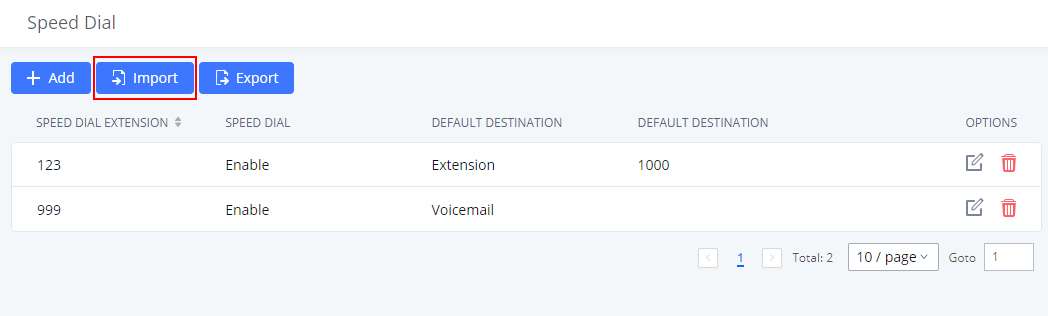
Then select the csv file of the speed dial entries and click ![]()
Export Speed Dial
To export speed dial entries, please click on export as the screenshot below shows, then choose the location where to save the csv file.
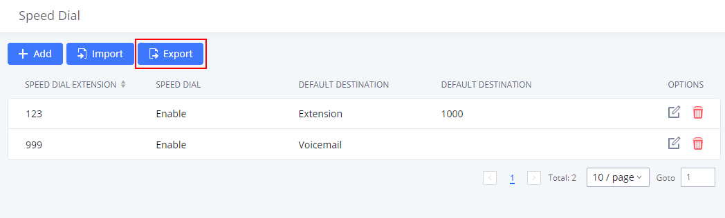
DISA
In many situations, the user will find the need to access his own IP PBX resources, but he is not physically near one of his extensions. However, he does have access to his own cell phone. In this case, we can use what is commonly known as DISA (Direct Inward System Access). Under this scenario, the user will be able to call from the outside, whether it is using his cell phone, pay phone, etc. After calling into the PBX, the user can then dial out via the SIP trunk connected to the PBX as it is an internal extension.
The PBX supports DISA to be used in IVR or inbound route. Before using it, create new DISA under Web GUI🡪Call Features🡪DISA.
- Click on to add a new DISA.
- Click on to edit the DISA configuration.
- Click on to delete the DISA.
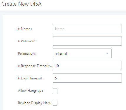
The following table details the parameters to set and configure DISA feature on PBX.
Name | Configure DISA name to identify the DISA. |
Password | Configure the password (digit only) required for the user to enter before using DISA to dial out. Note: The password must be at least 4 digits. |
Permission | Configure the permission level for DISA. The available permissions are "Internal", "Local", "National" and "International" from the lowest level to the highest level. |
Response Timeout | Configure the maximum amount of time the IPPBX will wait before hanging up if the user dials an incomplete or invalid number. The default setting is 10 seconds. |
Digit Timeout | Configure the maximum amount of time permitted between digits when the user is typing the extension. The default setting is 5 seconds. |
Allow Hangup | If enabled, during an active call, users can enter the IPPBX Hangup feature code (by default it is *0) to disconnect the call or hang up directly. A new dial tone will be heard shortly for the user to make a new call. The default setting is "No". |
Replace Display Name | If enabled, the IPPBX will replace the caller display name with the DISA name. |
Once successfully created, users can configure the inbound route destination as “DISA” or IVR key event as “DISA”. When dialing into DISA, users will be prompted with password first. After entering the correct password, a second dial tone will be heard for the users to dial out.
Callback
Callback is designed for users who often use their mobile phones to make long distance or international calls which may have high service charges. The callback feature provides an economic solution for reduce the cost from this.
The callback feature works as follows:
- Configure a new callback on the PBX.
- On the PBX, configure destination of the inbound route for callback.
- Save and apply the settings.
- The user calls number of the PBX using the mobile phone, which goes to callback destination as specified in the inbound route.
- Once the user hears the ringback tone from the mobile phone, hang up the call on the mobile phone.
- The PBX will call back the user.
- The user answers the call.
- The call will be sent to DISA or IVR which directs the user to dial the destination number.
- The user will be connected to the destination number.
In this way, the calls are placed and connected through trunks on the PBX instead of to the mobile phone directly. Therefore, the user will not be charged on mobile phone services for long distance or international calls.
To configure callback on the PBX, go to Web GUI🡪Call Features🡪Callback page and click on ![]() . Configuration parameters are listed in the following table.
. Configuration parameters are listed in the following table.
Event List
Besides BLF, users can also configure the phones to monitor event list. In this way, both local extensions on the same PBX and remote extensions on the VOIP trunk can be monitored. The event list setting is under Web GUI🡪Call Features🡪Event List.
- Click on “Add” to add a new event list.
- Sort selected extensions manually in the Eventlist
- Click on to edit the event list configuration.
- Click on to delete the event list.
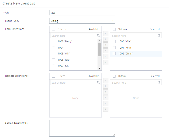
Remote extension monitoring works on the IPPBX via event list BLF, among Peer SIP trunks or Register SIP trunks (register to each other). Therefore, please properly configure SIP trunks on the IPPBX first before using remote BLF feature. Please note the SIP end points need support event list BLF in order to monitor remote extensions.
When an event list is created on the IPPBX and remote extensions are added to the list, the IPPBX will send out SIP SUBSCRIBE to the remote IPPBX to obtain the remote extension status. When the SIP end points register and subscribe to the local IPPBX event list, it can obtain the remote extension status from this event list. Once successfully configured, the event list page will show the status of total extension and subscribers for each event list. Users can also select the event URI to check the monitored extension’s status and the subscribers’ details.
URI | Configure the name of this event list (for example, office_event_list). Please note the URI name cannot be the same as the extension name on the IPPBX. The valid characters are letters, digits, _ and -. |
Local Extensions | Select the available extensions/Extension Groups listed on the local IPPBX to be monitored in the event list. |
Remote Extensions | If LDAP sync is enabled between the IPPBX and the peer IPPBX, the remote extensions will be listed under "Available Extensions". If not, manually enter the remote extensions under "Special Extensions" field. |
Special Extensions | Manually enter the remote extensions in the peer/register trunk to be monitored in the event list. Valid format: 5000,5001,9000 |
Feature Codes
Features codes allow performing certain actions using IP phones. The codes can be directly dialed on the IP phone. Certain feature codes require IVR input, therefore, the user needs to follow the IVR instructions and use DTMF to respond accordingly.
The PBX also allows user to one click enable / disable specific feature code as shown below:
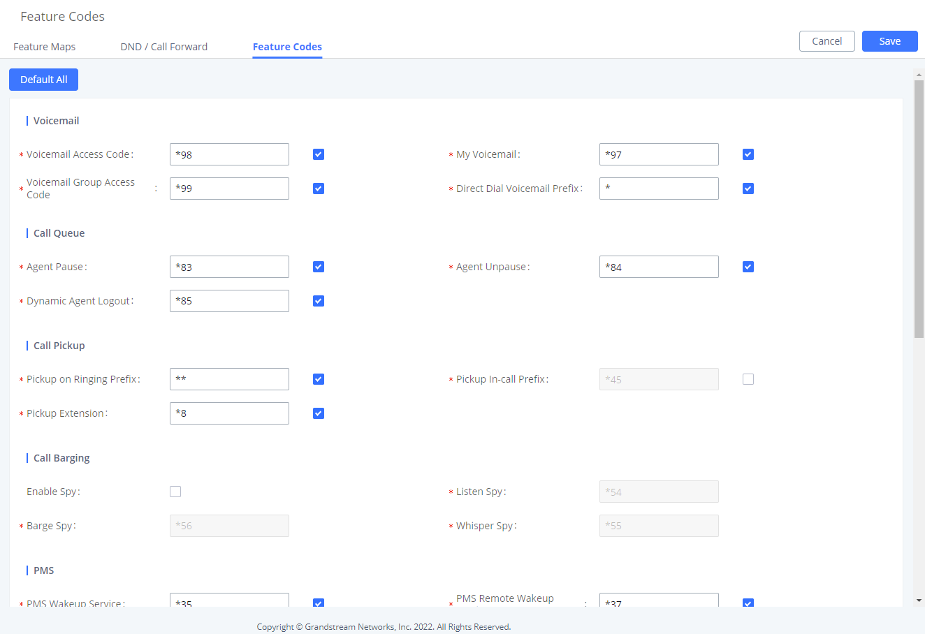
Fax/T.38
The PBX supports T.38 Fax It can convert the received Fax to PDF format and send it to the configured Email address. Fax/T.38 settings can be accessed via Web GUI🡪Call Features🡪FAX/T.38. The list of received Fax files will be displayed on the same web page for users to view, retrieve and delete.
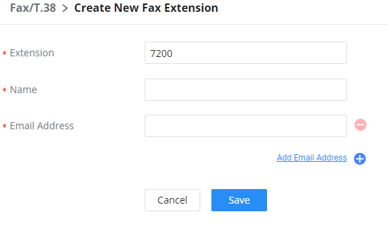
- Click on “Create New Fax Extension”. In the popped-up window, fill the extension, name, and Email address to send the received Fax to.
- Click on “Fax Settings” to configure the Fax parameters.
- Click on to edit the Fax extension.
- Click on to delete the Fax extension.
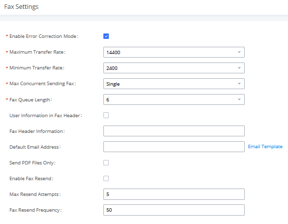
Enable Error Correction Mode | Configure to enable Error Correction Mode (ECM) for the Fax. The default setting is “Yes”. |
Maximum Transfer Rate | Configure the maximum transfer rate during the Fax rate negotiation. The possible values are 2400, 4800, 7200, 9600, 12000, and 14400. The default setting is 14400. |
Minimum Transfer Rate | Configure the minimum transfer rate during the Fax rate negotiation. The possible values are 2400, 4800, 7200, 9600, 12000, and 14000. The default setting is 2400. |
Max Concurrent Sending Fax | Configure the concurrent fax that can be sent by PBX. Two modes “Only” and “More” are supported.
Under this mode, the PBX allows only a single user to send a fax at a time.
Under this mode, the PBX supports multiple concurrent faxes sending by the users. By default, this option is set to “only”. |
Fax Queue Length | Configure the maximum length of Fax Queue from 6 to 10. The default setting is 6. |
If enabled, this will give users the option to send a special header in SIP fax messages. | |
Adds fax header into the fax file. | |
Default Email Address | Configure the Email address to send the received Fax to if the user’s Email address cannot be found. Note: The extension’s Email address or the Fax’s default Email address needs to be configured to receive Fax from Email. If neither of them is configured, Fax will not be received from email. |
Template Variables | Fill in the “Subject:” and “Message:” content, to be used in the Email when sending the Fax to the users. The template variables are:
|
Send PDF Files Only | If enabled, fax emails will no longer attach TIFF files. Only PDF files will be attached. |
Enables the fax resend option which allows the IPPBX to keep attempting to send faxes up to a specified amount of times. Additionally, if fax still fails to send, a Resend button will appear in the File Send Progress list in Other Features🡪Fax Sending to allow manual resending. | |
Configures the number of the maximum attempts to resend the fax. The default value is set to 5. | |
Fax Resend Frequency | Configures the Fax Resend Frequency. The default value is set to 50. |
Parking Lot
User can create parking lots and their related slots under Web GUI🡪 Call Features🡪 Parking Lot. In the Parking Lot page, users can create lots of their own. This allows different groups within an organization to have their own parking lots instead of sharing one large parking lot with others. While creating a new parking lot, users can assign it a range that they think is appropriate for the group that will use the parking lot.
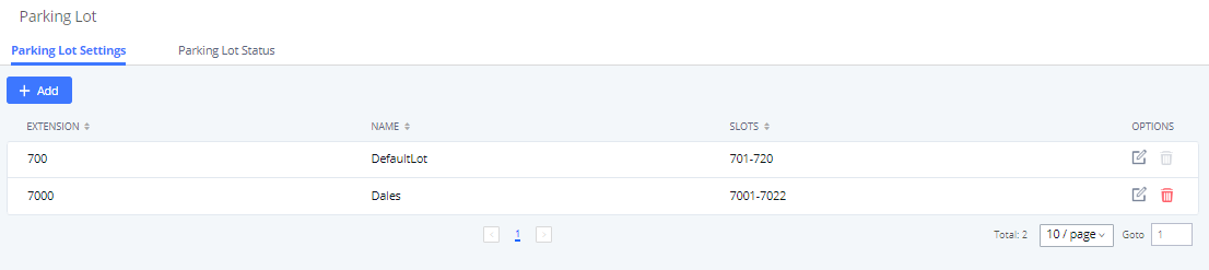
User can create a new Parking lot by clicking on button “Add” :
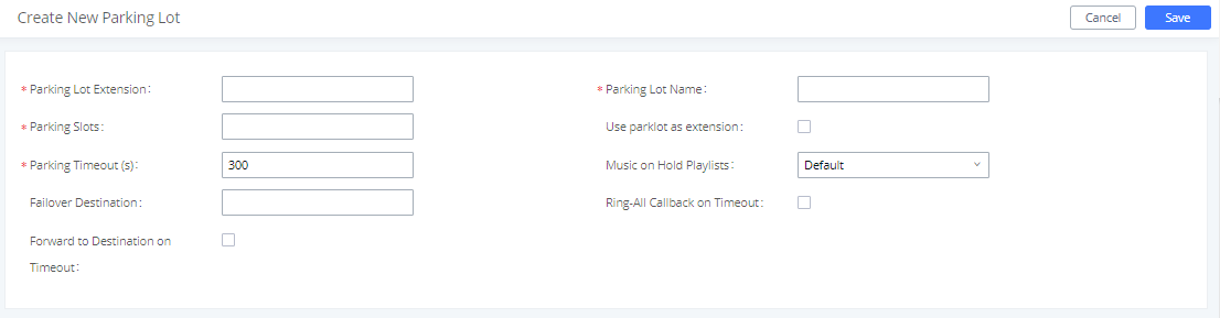
Parking Lot Extension |
|
Parking Lot Name |
|
Parked Slots |
|
Use Parklot as Extension |
|
| |
Music On Hold Classes | Select the Music on Hold Class. |
Configures a callback failover destination when the extension that is called back is busy. The call will be routed to the destination number and this reduces the chance of dropping parked calls. | |
If enabled, all registered endpoints of the extension will ring when callback occurs. Otherwise, only the original endpoint will be called back. | |
Forward to destination on timeout | If enabled, the call will be routed to the configured destination upon timeout. Otherwise, the call will be routed back to the original caller. |
Timeout Destination | This option appears once Forward to Destination on Timeout is enabled. Upon park timeout, the call will be routed to the configured destination. |
Adds an Alert-Info header to parking lot callbacks after the Parking Timeout has been reached. |
Call Park
The PBX provides call park and call pickup features via feature code.
Park a Call
There are two feature codes that can be used to park the call.
- Feature Maps🡪Call Park (Default code #72)
During an active call, press #72 and the call will be parked. Parking lot number (default range 701 to 720) will be announced after parking the call.
- Feature Misc🡪Call Park (Default code 700)
During an active call, initiate blind transfer (default code #1) and then dial 700 to park the call. Parking lot number (default range 701 to 720) will be announced after parking the call.
Retrieve Parked Call
To retrieve the parked call, simply dial the parking lot number and the call will be established. If a parked call is not retrieved after the timeout, the original extension who parks the call will be called back.
Monitor Call Park CID Name Information (GXP21xx, GRP261x Phones Only)
Users can see the CID name information of parked calls. VPK/MPKs must be configured as “Monitored Call Park” with the desired parking lot extension. The display will alternate between displaying the parking lot extension and the call’s CID name. There is no need to configure anything on the IPPBX.
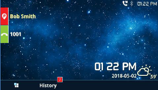
Emergency Calls
Emergency Calls
IPPBX supports configuration and management of numbers to be called in emergency situation, thus bypassing the regular outbound call routing process and allowing users in critical situation to dial out for emergency help with the possibility to have redundant trunks as point of exit in case one of the lines is down.
The PBX is fully compliant with Kari’s Law and Ray Baum’s Act, for more information, please refer to the following links:
https://www.fcc.gov/mlts-911-requirements
https://documentation.grandstream.com/knowledge-base/emergency-calls/
In addition, Emergency calls can be automatically recorded by toggling on the new Auto Record and recordings can be viewed in the new Emergency Recordings tab on the same page. Additionally, users can have these recordings be sent to the configured email address(es).
Email alerts are also supported after enabling the notification for the event under “Maintenance 🡪 System Events”
To configure emergency numbers, users need to follow below steps:
- Navigate on the web GUI under “Call Features 🡪 Emergency Calls”
- Click on
 to add a new emergency number.
 - Configure the required fields “Name, Emergency Number and Trunk(s) to be used to reach the number”.
- Save and apply the configuration.
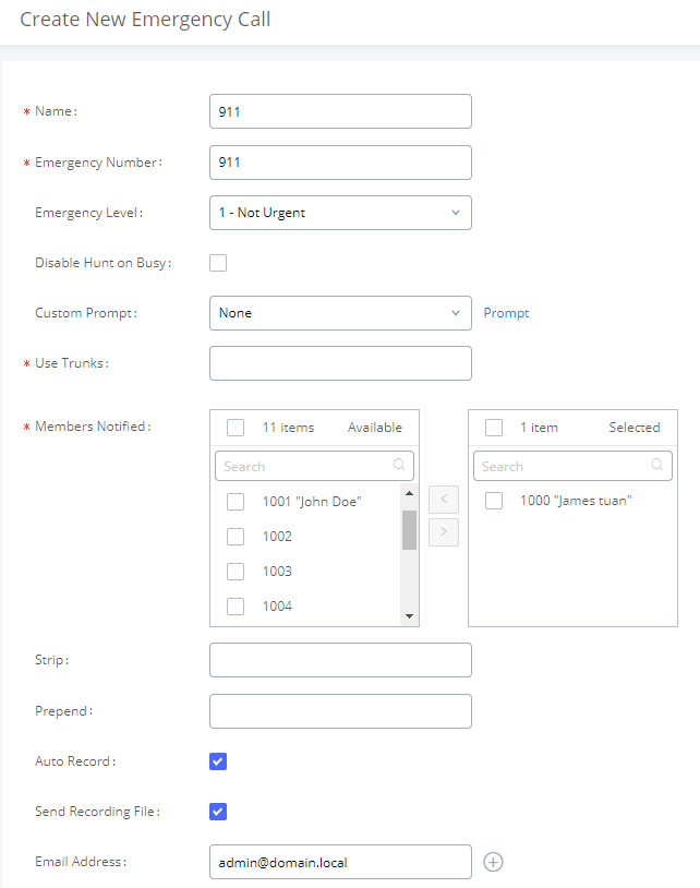
The table below gives more description of the configuration Parameters when creating emergency numbers.
Name | Configure the name of the emergency call. For example, “emergency911″,”emergency211” and etc. |
Emergency Number | Config the emergency service number. For example,”911″,”211″ and etc. |
Emergency Level | Select the emergency level of the number. Level “3” means the most urgent. |
Disable Hunt on Busy | If this option is not enabled, when the lines of trunks which the coming emergency call routes by are completely occupied, the line-grabbing function will automatically cut off a line from all busy lines so that the coming emergency call can seize it for dialing out. Note: This option is not enabled by default. |
Custom Prompt | This option sets a custom prompt to be used as an announcement to the person receiving an emergency call. The file can be uploaded from the page “Custom Prompt”. Click “Prompt” to add an additional record. |
Use Trunks | Select the trunks for the emergency call. Select one trunk at least and select five trunks at most. |
Members Notified | Select the members who will be notified when an emergency call occurs. |
Strip | Specify the number of digits that will be stripped from the beginning of the dialed number before the call is placed via the selected trunk. |
Prepend | Specify the digits to be prepended before the call is placed via the trunk. Those digits will be prepended after the dialing number is stripped. |
Auto Record | If enabled, the calls using this extension or trunk will be automatically recorded, default is disabled Note: Emergency recording will be also available under Emergency Recording Tab. |
Send Recording File | If Enabled the recordings will be sent to the configured Email address(es) |
Email Address | Used to specify the Email address(es) for Emergency calls recordings. |
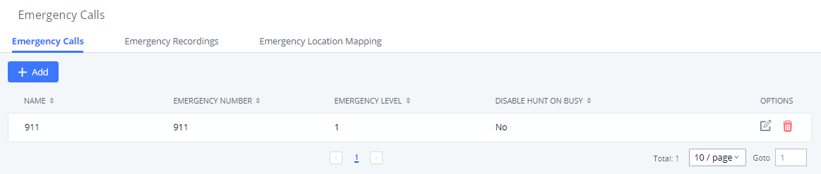
Emergency Recordings
The IPPBX allows recording emergency calls and they can be found under WebUI → Call Feature → Emergency Calls → Emergency Recordings
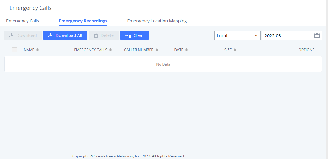
Emergency Location Mapping
In compliance with Kari’s Law and the Ray Baum’s Act, IPPBX’s Emergency Calls feature supports
emergency location mapping. This will allow users to associate subnets with emergency location
identification numbers (ELINs), which can then be used by E911 service providers for example to determine the exact location of callers. The new options can be found under Call Features→Emergency
Calls→Emergency Location Mapping.
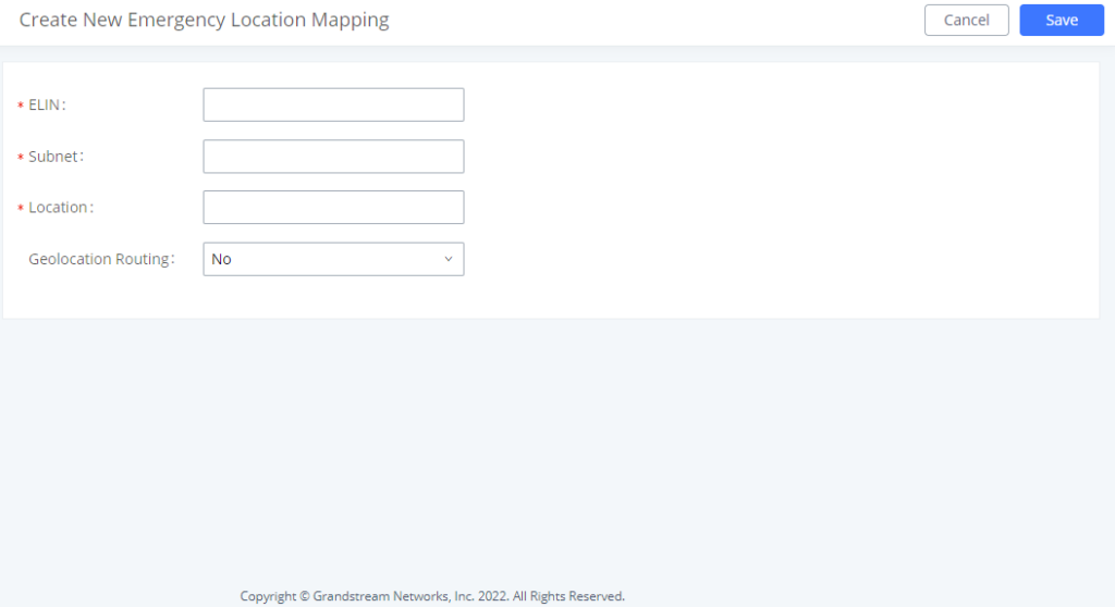
- ELIN: The emergency location identification number registered with the E911 provider. This number will be sent out as the emergency call’s CID number.
- Subnet: The network subnet that the ELIN will be associated with. The ELIN that is sent to E911 providers is based on the subnet that a calling endpoint is registered from. Example: “xxx.xxx.xxx.xxx/24” or “xxxx:xxxx:xxxx:xxxx:xxxx:xxxx:xxxx:xxxx/64”.
- Location: Location associated with the configured subnet. This is used for the IPPBX administrator’s reference.
- Geolocation Routing: Toggles whether to include the Geolocation header in the emergency call SIP INVITE message. The Location field value will be used as the Geolocation header value.
Scheduled Call
Call scheduler feature allows the user to schedule a wakeup call to a specific extension. The user can choose the time and date of the call, and when the time arrives, a call will be initiated to designated extension(s). When the call is answered, the chosen prompt will be played.
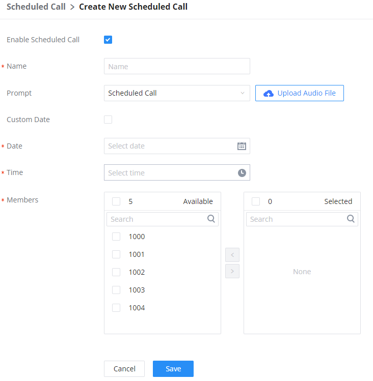
Fax Sending
The IPPBX supports sending Fax via Web GUI . This feature can be found on Web GUI🡪Other Features🡪Fax Sending page. The user can enter the number of the destination, then the fax will be sent to a fax gateway on the receiving end.
After entering the fax number, please uploade the pdf file that you wish to send as a fax.
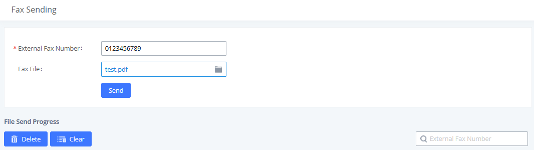
After that you can see the ongoing sending operation on the progress bar.
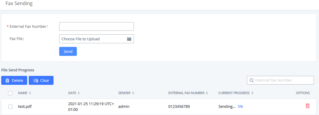
Announcement Center
The IPPBX supports Announcement Center feature which allows users to pre-record and store voice message into the IPPBX with a specified code. The users can also create group with specified extensions. When the code and the group number are dialed together in the combination of code + group number, the specified voice message is sent to all group members and only extensions in the group will hear the voice message.
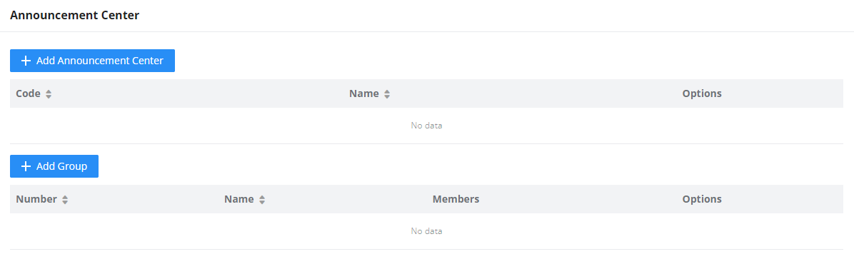
Announcement Center feature can be found under Web GUI🡪Other Features🡪Announcement Center. The following example demonstrates the usage of this feature.
- Click
 to add new group.
 - Give a name to the newly created group.
- Create a group number which is used with code to send voice message.
- Select the extensions to be included in the group, who will receive the voice message.
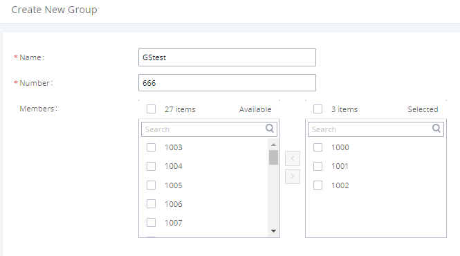
In this example, group “Test” has number 666. Extension 1000, 1001 and 1002 are in this group.
- Click
 to create a new Announcement Center.
 - Give a name to the newly created Announcement Center.
- Specify the code which will be used with group number to send the voice message to.
- Select the message that will be used by the code from the Custom Prompt drop down menu. To create a new Prompt, please click “Prompt” link and follow the instructions in that page.
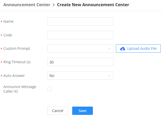
Name | Configure a name for the newly created group to identify the group. Note: Name cannot exceed 64 characters. |
Number | Configure the group number. The group number is used in combination with the code. For example, if group number is 666, and code is 55. The user can dial 55666 to send prompt 55 to all members in group 666. Note: The combination number must not conflict with any number in the system such as extension number or conference number and cannot exceed 64 characters. |
Internal Members | Choose the local extensions to add to the group. |
LDAP Members | Choose the LDAP contacts to add to the group. |
Custom Members | Enter the custom phone numbers to add to the group. Note: The maximum number of custom numbers which can be added are 50 custom number. |
Code and Group number are used together to direct specified message to the target group. All extensions in the group will receive the message. For example, we can send code 55 to group 666 by dialing 55666 from any extension registered to the PBX. All the members in group 666 which are extension 1000, 1001 and 1002 will receive this voice message after they pick up the call.
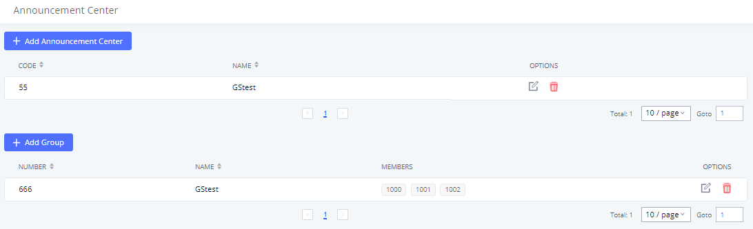
Shared Call Appearance (SCA)
Shared Call Appearance (SCA) functionality has been added to the PBX. With SCA, users can assign multiple devices to one extension, configure endpoints to monitor that extension, make actions on behalf of that extension such as viewing call status and placing and receiving calls, and even barging into existing calls. To configure the SCA functionality, please follow the steps below:
- Users can enable SCA by navigating to the Extensions page, editing the desired extension, and enabling the option SCA.
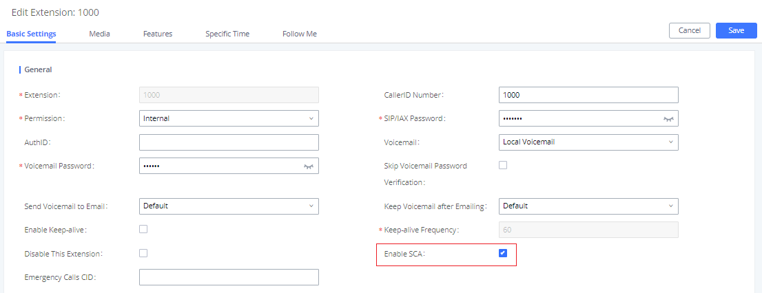
- After enabling the option, navigate to Call Features🡪SCA. The newly enabled SCA extension will be listed. Click the “+” button under the Options column to add a number that will share the main extension’s call appearance, which will be called private numbers.
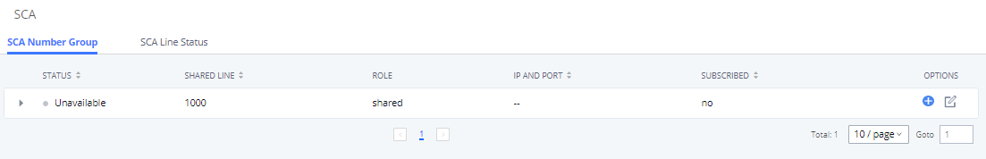
- Configure the private number as desired.
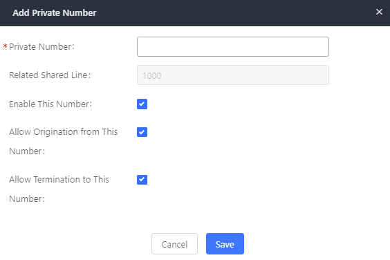
- Once the private number has been created, users must now register a device to it. To properly register a device to the private number, use the configured private number as the SIP User ID. Auth ID and Password will be the same as the main extensions. Once registration is complete, SCA is now configured.
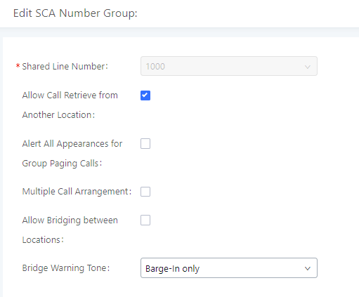
- Next, configure the VPK or MPK to Shared for both the main extension and the private number. SCA is now configured for both endpoint devices.
The following table describe the SCA Number configuration setting:
Private Number | Configures the private number for the SCA. |
Related Shared Line | Display the related shared line. |
Enable This Number | Whether enable this private number. If not enabled, this private number is only record in DB, it will not affect other system feature. |
Allow Origination from This Number | Enable this option will allow calling from this private number. By default, it is enabled. |
Allow Termination to This Number | Enable this option will allows calls to this private number. By default, it is enabled. |
The following table describes the options available when editing the SCA number:
Shared Line Number | While SCA is enabled, this number will be the same as the extension number. |
Allow Call Retrieve from Another Location | Allows remote call retrieval. Must be enabled in public hold. By default, it is enabled. |
Alert All Appearances for Group Paging Calls | Allows all SCA group members to ring when the SCA shared number is paged. If disabled, only the SCA shared number will ring when paged. By default, it is disabled. |
Multiple Call Arrangement | Allows simultaneous calls in an SCA group. By default, it is disabled. |
Allow Bridging between Locations | Allows location bridging for SCA group. Must be enabled when using the Barge-In feature. By default, it is disabled. |
Bridge Warning Tone | Configures the notification in the bridge when another party join.
By default, it is set to “Barge-In Only”. |
Announcement
The Announcement feature (not to be confused with Announcement Paging and Announcement Center) is a feature that allows users to set an unskippable audio file to play to callers before routing them to a configured destination. Announcements can be configured as a destination in the Inbound Routes page.
To configure Announcement, users need to follow below steps:
- Navigate on the web GUI under “Call Features 🡪 Announcement”
-
Click on
to add a new Announcement.
- Configure the required fields Name, Prompt, Default Destination to be used for the announcement.
Save and apply the configuration.
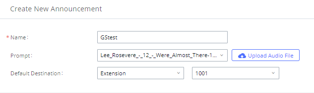
The table below gives more description of the configuration parameters when creating Announcement.
Name | Configure the name of the Announcement. |
Prompt | Audio file that needs to be uploaded in order to be played for a specific destination. |
Default Destination | Select the destination where to play the audio file. |
MESSAGING
In this category, the user can configure settings related to the messaging features offered by the PBX. This includes instant messaging feature offered by the PBX, as well as Live Chat, and Message Broadcast.
IM Settings
In this section, the user can configure settings related to instant messaging feature. The user can either options related to the local instant messaging service or the cloud instant messaging service.
IM Settings
In IM Settings tab, the user can choose to enable or disable read receipts when exchanging messaging using Wave.
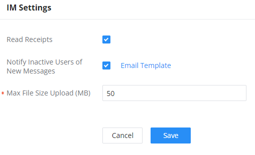
Parameter | Description |
Read Receipts | Toggle on/off r the read receipts in the instant messages exchanged in Wave. |
Notify Inactive Users of New Messages | If an extension under this server has not logged into Wave for more than 7 days, and a new message is received, an email notification will be sent to the extension notifying them of the amount of direct messages and @mentions received in the last 24 hours. Applies to both local IM and Cloud IM. |
Max File Size Upload (MB) | Configures the maximum size of individual files users can upload to Wave chat. Only applicable when using local IM.
|
Cloud IM Service
After enabling Cloud IM, it means that all IM data in Wave is stored in the external server Cloud IM, and is no longer stored locally in UCM.GDMS can configure the External Cloud IM service for UCM devices. At this time, the UCM device synchronizes the configuration item information.
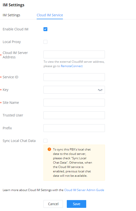
Cloud IM Service | |
Enable Cloud IM | If you have purchased the Cloud IM package or purchased the Grandstream IM server, you can configure it. If you have not purchased it, the configuration will not take effect, but PBX local IM service is allowed. Please note that after enabling this feature, local chat data will not be visible. |
Local Proxy | If enabled, the local proxy will be used to forward files and text messages if the IM server cannot be connected to upon Wave login due to certificate issues. |
Cloud IM Server Address | The address of the server that provides IM service, you can fill in the address of the Cloud IM server provided by the RemoteConnect package or the IM server address of the GDMS. |
Service ID | The service ID of the Cloud IM server. |
Key | The Key to the Cloud IM server. |
Site Name | Enter the name of the site. |
Trusted User | The trusted user of the cloud IM. Only letters, numbers, and special characters are allowed. |
Prepend | As the extension prefix, it is added before the extension number. |
Sync Local Chat Data | Syncing existing local chat data to Cloud IM server. The Wave chat feature will not be available during the syncing process. It is recommended to avoid syncing during active working hours. - Time Range
- Data Type
|
Live Chat
Live Chat feature allows to create chat channels that can be embedded on your website to enable your client to reach your customer service more easily. The client can contact your agents through text chat, and the agent can initiate a call with the client.
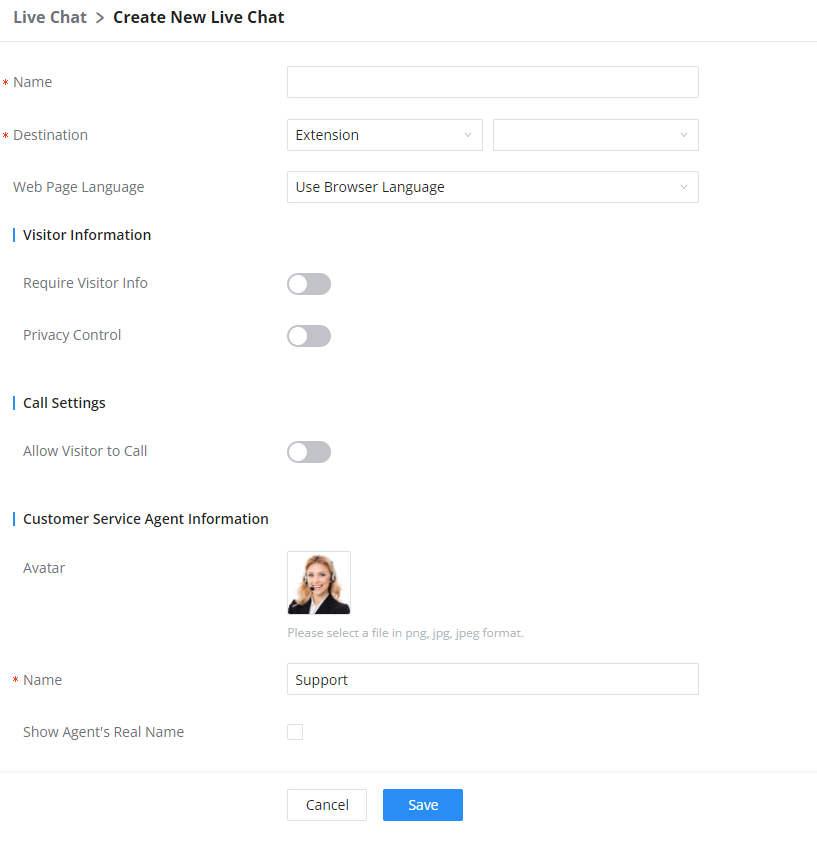
Name | Enter the name of the Live Chat |
Destination | Configure the destination of this Live Chat. |
Web Page Language | Configure the language of visitor page. |
Visitor Information | |
Require Visitor Info | Configure the visitor information required to start a live chat session. |
Privacy Control | If enabled, visitors must consent to allow the processing of personal data and cookies before entering Live Chat. |
Call Settings | |
Allow Visitor To Call | If enabled, visitors will have the option to call the configured destination from this Live Chat. |
Customer Service Agent Information | |
Avatar | Upload the avatar of the agent. Please select a png, jpg, or jpeg format file. |
Name | Enter the name of the agent. |
Show Agent's Real Name | Enable this option to show the agent's real name in the live chat. |
Chat Settings | |
Welcome Message | Configure the initial message to display to visitors when they first enter the live chat session. |
Reply to First Message | Configure the message to send to visitors in response to their first message. |
Visitor Chat Log Retention Time (days) | This value determines how long a visitor's chat history will be kept before it's deleted automatically. |
Live Chat Link Address | This link can be embedded onto web pages. Clicking it will connect visitors to the configured Live Chat destination. This link can also be entered directly into the browser address bar for testing purposes. |
Message Broadcast
Message broadcast feature allows the administrator to broadcast a text message to all the endpoints selected by the administrator. The administrator can select departments or individual extensions to boardcast a text message.
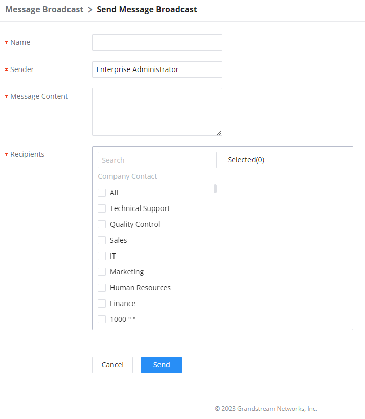
PBX SETTINGS
In this category, the user can find the settings related to the PBX operations, such as, extension range settings, SIP settings, RTP settings, Music on Hold settings
General Settings
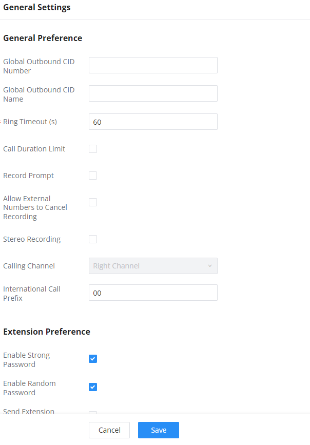
General Preferences | |
Global Outbound CID | Configure the global CallerID used for all outbound calls when no other CallerID is defined with higher priority. If no CallerID is defined for extension or trunk, the global outbound CID will be used as CallerID. |
Global Outbound CID Name | Configure the global CallerID Name used for all outbound calls. If configured, all outbound calls will have the CallerID Name set to this name. If not, the extension’s CallerID Name will be used. |
Ring Timeout | Configure the number of seconds to ring an extension before the call goes to the user’s voicemail box. The default setting is 60. |
Call Duration Limit | Block calls for the configured duration. If Extensions->Features->Call Duration Limit and Outbound Routes->Call Duration Limit are not configured, General Settings->Call Duration Limit will be used. |
Record Prompt | If enabled, users will hear voice prompt before recording is started or stopped. For example, before recording, the IPPBX will play voice prompt “The call will be recorded”. The default setting is “No”. |
Allow External Numbers to Cancel Recording | If enabled, external call parties will be given the option to decline the recording of calls. The IVR will prompt the user to dial *3 in order to cancel the call recording. |
Stereo Recording | If enabled, the caller and callee's audio will be split into two channels during call recording. Not applicable to calls with more than 2 parties. |
Calling Channel | Configure the audio channels for the calling party and the called party. If the caller is selected as the right channel, the callee will be used for the left channel, and vice-versa. Note: This option will be available when "Stereo Recording" is enabled. |
International Call Prefix | When this configuration is empty, International Call Prefix can be empty or +. |
Extension Preferences | |
Enforce Strong Password | If enabled, a strong password policy will be enforced. This does not affect user login passwords, which must be strong. |
Enable Random Password | If enabled, the extension will created with a randomly generated password. |
Send Extension Update Emails | If enabled, an email will be sent to an extension's configured email address after creating it or modifying that extension's settings. |
Disable Extension Range | If set to “Yes”, users could disable the extension range pre-configured/configured on the IPPBX. The default setting is “No”.Note: It is recommended to keep the system assignment to avoid inappropriate usage and unnecessary issues. |
Extension Ranges | The default extension range assignment is:
|
Clicking this button will reset the extension range to their default values. | |
SIP Settings
General
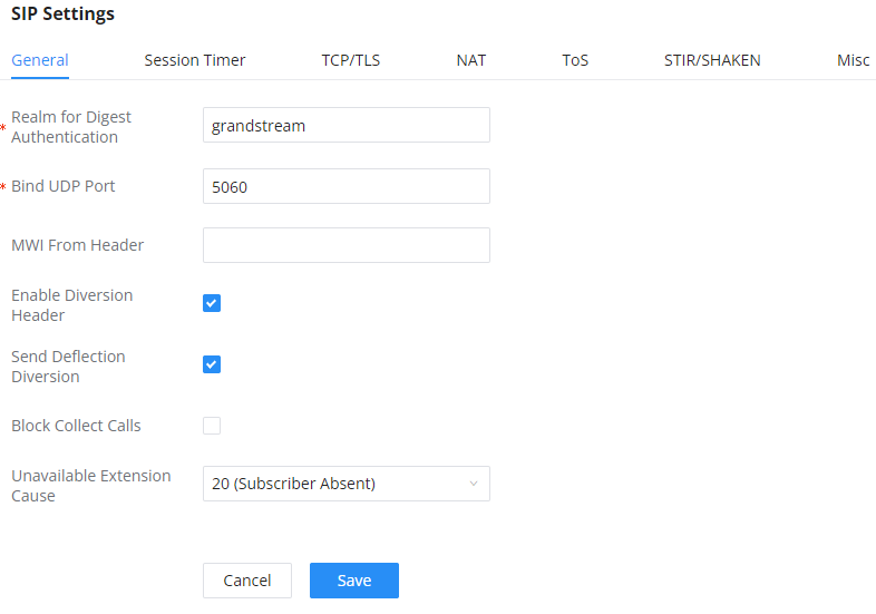
Realm For Digest Authentication | Configure this as the host name or domain name of the PBX. Realms MUST be globally unique according to RFC3261. |
Bind UDP Port | Configure the UDP port used for SIP. The default setting is 5060. |
Bind IPv4 Address | Configure the IPv4 address to bind to. "0.0.0.0" means to bind to all IP addresses. |
Bind IPv6 Address | Configure the IPv6 address to bind to. "[::]" means to bind to all IP addresses. |
MWI From Header | If disabled, the server will not transfer the Diversion Header |
Enable Diversion Header | If set to “No”, all transfers initiated by the endpoint in the IPPBX will be disabled (unless enabled in peers or users). The default setting is “Yes”. |
Send Deflection Diversion | If 'Enable Diversion Header' and this option enabled, the INVITE request will contain Diversion with reason 'deflection' while the inbound call been routed to an external number. |
Block Collect Calls | If enabled, collect calls will be blocked. Note: Collect calls are indicated by the header “P-Asserted-Service-Info: service-code=Backward Collect Call, P-Asserted-Service-Info: service-code=Collect Call”. |
Session Timer
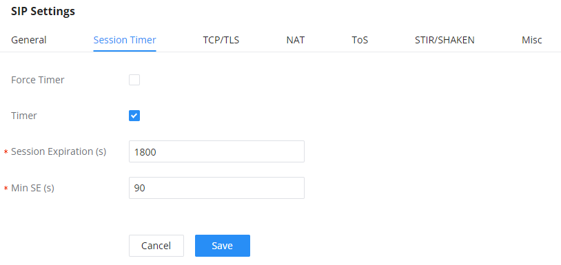
If checked, always request, and run session timer. | |
Timer | If checked, run session timer only when requested by other UA. |
Session Expire | Configure the maximum session refresh interval (in seconds). Default is 1800. |
Min SE | Configure the minimum session refresh interval (in seconds). The default setting is 90. |
TCP/TLS
In this page the administrator can configure the options related to registering SIP endpoints on the PBX.
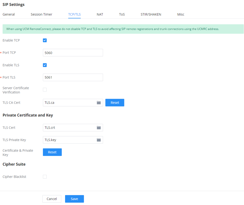
TCP Enable | Configure to allow incoming TCP connections with the UCM630X. The default setting is “No”. |
TCP Bind IPv4 Address | Configure the IP address for the TCP server to bind to. “0.0.0.0” means binding to all interfaces. The port number is optional, and the default port number is 5060. For example, 192.168.1.1:5062. |
TCP Bind IPv6 Address | Configure the IPv6 address for the TCP server to bind to. “[::]” means bind to all interfaces. The port number is optional with the default being 5060. For example, [2001:0DB8:0000:0000:0000:0000:1428:0000]:5060. |
TLS Enable | Configure to allow incoming TLS connections with the UCM630X. The default setting is “Yes”. |
TLS Bind IPv4 Address | Configure the IPv4 address for TLS server to bind to. “0.0.0.0” means binding to all interfaces. The port number is optional, and the default port number is 5061. For example, 192.168.1.1:5063. Note: The IP address must match the common name (host name) in the certificate so that the TLS socket will not bind to multiple IP addresses. |
TLS Bind IPv6 Address | Configure the IPv6 address for TLS server to bind to. “[::]” means bind to all interfaces. The port number is optional with default being 5061. For example, [2001:0DB8:0000:0000:0000:0000:1428:0000]:5061. Note: The IP address must match the common name (host name) in the certificate so that the TLS socket will not bind to multiple IP addresses. |
TLS Do Not Verify | If enabled, the TLS server’s certificate will not be verified when acting as a client. The default setting is “Yes”. |
TLS Self-Signed CA | This is the CA certificate if the TLS server being connected to requires self-signed certificate, including server’s public key. This file will be renamed as “TLS.ca” automatically. |
Clicking on this button will reset the certificates. | |
Private Certificate and Key | |
TLS Cert | This is the Certificate file (*.pem format only) used for TLS connections. It contains private key for client and signed certificate for the server. This file will be renamed as “TLS.pem” automatically. Note: The size of the uploaded certificate file must be under 2MB. |
TLS Key | This file must be named with the CA subject name hash value. It contains CA’s (Certificate Authority) public key, which is used to verify the accessed servers. Note: The size of the uploaded CA certificate file must be under 2MB. |
Clicking on this button will reset the certificates. | |
Cipher Suite | |
Restrict Cipher List | By default, all SIP TLS encryption suites are in effect on the system, and when turned on, you can configure the encryption suites allowed to be used. |
Cipher Suite | Select the encryption suites that are allowed to be used for SIP TLS connections, in the order of priority as configured. |
NAT
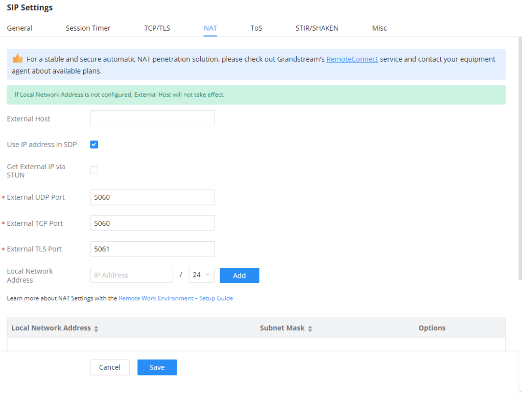
External Host | Configure a static IP address and port (optional) used in outbound SIP messages if the IPPBX is behind NAT. If it is a host name, it will only be looked up once. |
Use IP address in SDP | If enabled, the SDP connection will use the IP address resolved from the external host. |
External UDP Port | Configure externally mapped UDP port when the PBX is behind a static NAT or PAT. |
External TCP Port | Configure the externally mapped TCP port when the IPPBX is behind a static NAT or PAT. |
External TLS Port | Configures the externally mapped TLS port when IPPBX is behind a static NAT or PAT. |
Local Network Address | Specify a list of network addresses that are considered inside of the NAT network. Multiple entries are allowed. If not configured, the external IP address will not be set correctly. A sample configuration could be as follows: 192.168.0.0/16 |
ToS
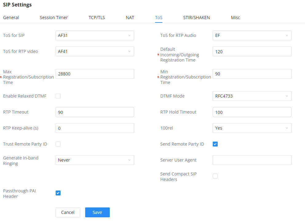
ToS for SIP | Configure the Type of Service for SIP packets. The default setting is None. |
ToS for RTP Audio | Configure the Type of Service for RTP audio packets. The default setting is None. |
ToS for RTP Video | Configure the Type of Service for RTP video packets. The default setting is None. |
Default Incoming/Outgoing Registration Time | Configure the default duration (in seconds) of incoming/outgoing registration. The default setting is 120. |
Max Registration/Subscription Time | Configure the maximum duration (in seconds) of incoming registration and subscription allowed by the IPPBX. The default setting is 3600. |
Min Registration/Subscription Time | Configure the minimum duration (in seconds) of incoming registration and subscription allowed by the IPPBX. The default setting is 60. |
Enable Relaxed DTMF | Select to enable relaxed DTMF handling. The default setting is “No”. |
DTMF Mode | Select DTMF mode to send DTMF. The default setting is RFC4733. If “Info” is selected, SIP INFO message will be used. If “Inband” is selected, a-law or u-law are required. When “Auto” is selected, “RFC4733” will be used if offered, otherwise “Inband” will be used. The default setting is “RFC4733”. |
RTP Timeout | During an active call, if there is no RTP activity within the timeout (in seconds), the call will be terminated. The default setting is no timeout. Note: This setting does not apply to calls on hold. |
RTP Hold Timeout | When the call is on hold, if there is no RTP activity within the timeout (in seconds), the call will be terminated. This value of RTP Hold Timeout should be larger than RTP Timeout. The default setting is no timeout. |
This feature can be used to avoid abnormal call drop when the remote provider requires RTP traffic during proceeding. For example, when the call goes into voicemail and there is no RTP traffic sent out from IPPBX, configuring this option can avoid voicemail drop. When configured, RTP keep-alive packet will be sent to remote party at the configured interval. If set to 0, RTP keep-alive is disabled. | |
100rel | Configure the 100rel setting on IPPBX. The default setting is “Yes”. |
Trust Remote Party ID | Configure whether the Remote-Party-ID should be trusted. The default setting is “No”. |
Send Remote Party ID | Configure whether the Remote-Party-ID should be sent or not. The default setting is “No”. |
Generate In-Band Ringing | Configure whether the PBX should generate Inband ringing or not. The default setting is “Never”.
|
Server User Agent | Configure the user agent string for the PBX. |
Send Compact SIP Headers | If enabled, compact SIP headers will be sent. The default setting is “No”. |
Passthrough PAI Header | Passthrough PAI Header |
STIR/SHAKEN
To prevent robocalls, IPPBX now supports STIR/SHAKE protocols. Related options have been added as a new tab in the SIP Settings page.
Clicking on the Add button will show the following window:
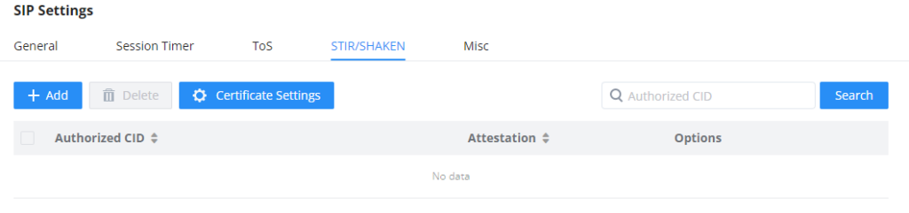
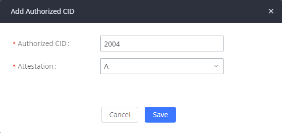
Authorized CID | Configure the authorized CID. |
Attestation | Configure the attestation level, which is the level of confidence of the carrier that the CID has not been spoofed. The following options are available:
|
Clicking on the Certificate Settings button will bring up the following window:
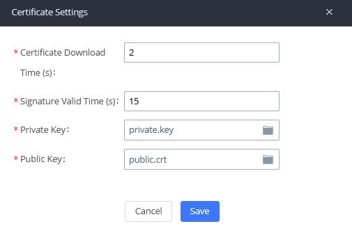
Certificate Download Time (s) | Configure the public key download timeout period, the default value is 2 seconds. |
Signature Valid Time (s) | Configure the validity period of the digital signature, the default value is 15 seconds. |
Private Key | Configure the Private key. Note: The uploaded file must be less than 2MB in file size, only supports the .key format and must be ECC type. This file will automatically be renamed to “private.key”. |
Public Key | Configure the Public Key. Note: The uploaded file must be less than 2MB in file size, only supports the .crt format and must be ECC type. This file will automatically be renamed to “public.crt”. |
Misc
Outbound SIP Registrations | |
Register Timeout | Configure the register retry timeout (in seconds). The default setting is 20. |
Register Attempts | Configure the number of registration attempts before the IPPBX gives up. The default setting is 0, which means the IPPBX will keep trying until the server side accepts the registration request. |
Video | |
Max Bit Rate (kb/s) | |
Support SIP Video | Select to enable video support in SIP calls. The default setting is “Yes”. |
Reject Non-Matching INVITE | If enabled, when rejecting an incoming INVITE or REGISTER request, the IPPBX will always reject with “401 Unauthorized” instead of notifying the requester whether there is a matching user or peer for the request. This reduces the ability of an attacker to scan for valid SIP usernames. The default setting is “No”. |
SDP Attribute Passthrough | |
Enable Attribute Passthrough | If enabled, and IPPBX receives a call that contains unknown FEC/FECC/FBCP attributes, they will be passed through the IPPBX unmodified. |
Early Media | |
Enable Use Final SDP | If enabled, call negotiation will use final response SDP. |
Ignore 180 Response | If enabled, ignore the ringing indication if has sent 183 response. |
Blind Transfer | |
Allow callback when blind transfer fails | If enabled, the IPPBX will call back to the transferrer when blind transfer fails (due to the destination being busy or not answering). Note: This feature applies only to internal calls. |
Blind transfer timeout | Configure the amount of time in seconds that the transferred party will wait for the destination to answer before being redirected back to the transferrer. Default is 60 seconds. |
DNS | |
DNS mode | This option affects the DNS query only during Calls. When you choose A&AAAA, IPPBX will do both A and AAAA type DNS query; when you chose A, IPPBX will only do A type DNS query; and when you chose AAAA, IPPBX will only do AAAA type DNS query. |
Hold | |
Forward HOLD Requests | Configure the IPPBX to forward HOLD requests instead of processing holds internally. This serves to meet the standards set by some providers that require HOLD requests to be passed along from endpoint to endpoint. This option is disabled by default. Note: Enabling this option may cause hold retrieval issues and MOH to not be heard. |
RTP Settings
RTP Settings
RTP Start | Configure the RTP port starting number. The default setting is 10000. |
RTP End | Configure the RTP port ending address. The default setting is 20000. |
Strict RTP | Configure to enable or disable strict RTP protection. If enabled, RTP packets that do not come from the source of the RTP stream will be dropped. The default setting is "Disable". |
RTP Checksums | Configure to enable or disable RTP Checksums on RTP traffic. The default setting is "Disable". |
ICE Support | Configure whether to support ICE. The default setting is enabled. ICE is the integrated use of STUN and TURN structure to provide reliable VoIP or video calls and media transmission, via a SIP request/ response model or multiple candidate endpoints exchanging IP addresses and ports, such as private addresses and TURN server address. |
STUN Server | Configure STUN server address. STUN protocol is a Client/Server and also a Request/Response protocol. It is used to check the connectivity between the two terminals, such as maintaining a NAT binding entries keep-alive agreement. The default STUN Server is stun.ipvideotalk.com. Valid format: [(hostname | IP-address) [':' port] The default port number is 3478 if not specified. |
BFCP UDP Start | Configure BFCP UDP port starting number. The default setting is 50000. |
BFCP UDP End | Configure BFCP UDP port ending number. The default setting is 52999. |
BFCP TCP Start | Configure BFCP TCP port starting number. The default setting is 53000. |
BFCP TCP End | Configure BFCP TCP port ending number. The default setting is 55999. |
TURN Server | Configure TURN server address. TURN is an enhanced version of the STUN protocol and is dedicated to the processing of symmetric NAT problems. |
TURN Server Name | Configure turn server account name |
TURN Server Password | Configure turn server account password. |
Connection Protocol | Protocol used to connect to the TURN server. |
Number of ICE Candidates | This configures the number of pre-collected ICE candidates to gather and send to remote peers. The higher the number, the greater the network traffic consumption. |
Payload Type Settings
The PBX payload type for audio codecs and video codes can be configured here.
Audio Codecs | |
AAL2-G.726 | ADPCM (G.726, 32kbps, AAL2 codeword packing). |
DTMF | Dual-tone Multi-frequency. |
G.721 Compatible | G.721 Compatible |
G.726 | ADPCM (G.726, 32kbps, RFC3551 codeword packing). |
ILBC | ILBC Free Compression. |
Opus | Opus |
G.722.1 | G.722.1: Low-complexity coding, 24kbps |
G.722.1C | G.722.1C: Low-complexity coding, 48kbps |
Audio FEC Payload Type | Audio FEC Payload Type |
Audio RED Payload Type | Audio RED Payload Type |
Video Coding | |
H.264 | H.264 Video. |
H.265 | H.265 Video. |
H.263P | H.263+ Video. |
VP8 | VP8 Video. |
Other Settings | |
Main Video FEC | Main Video FEC. |
RTP FECC | RTP FECC |
RTX | Used for packet retransmission. UCM supports only video RTP retransmission. |
Music On Hold
Music On Hold settings can be accessed via Web GUI🡪PBX Settings🡪Music On Hold. In this page, users could configure music on hold class and upload music files. The “default” Music On Hold class already has 5 audio files defined for users to use.
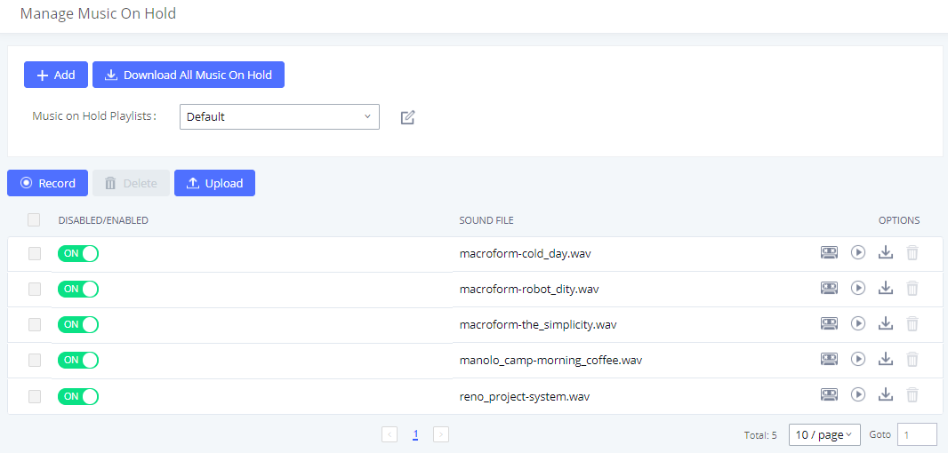
- Click on “Create New MOH Class” to add a new Music On Hold class.
- Click on to configure the MOH class sort method to be “Alpha” or “Random” for the sound files.
- Click on next to the selected Music On Hold class to delete this Music On Hold class.
- Click on
 to start uploading. Users can upload:
 - Single files with 8KHz Mono Music file, or
- Music on hold files in a compressed package with .tar, .tar.gz and .tgz as the suffix. The file name can only be letters, digits, or special characters -_
- the size for the uploaded file should be less than 30M, the compressed file will be applied to the entire MoH.
- Users could also download all the music on hold files from IPPBX. In the Music On Hold page, click on
 and the file will be downloaded to your local PC.
 - Click on
 to disable it from the selected Music On Hold Class.
 - Click on
 to enable it from the selected Music On Hold Class.
 - Select the sound files and click on
 to delete all selected Music On Hold files.
The PBX allows Users to select the Music On Hold file from WebGUI to play it. The PBX will initiate a call to the selected extension and play this Music On Hold file once the call is answered.
Steps to play the Music On Hold file:
- Click on the
 button for the Music On Hold file.
 - In the prompted window, select the extension to playback and click
 .
.
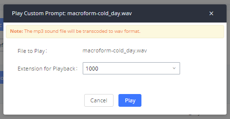
- The selected extension will ring.
- Answer the call to listen to the music playback.
Users could also record their own Music On Hold to override an existing custom prompt, this can be done by following those steps:
- Click on
 .
. - A message of confirmation will pop up, as shown below.
- Click
 .
. - In the prompted window, select the extension to playback and click
 .
.
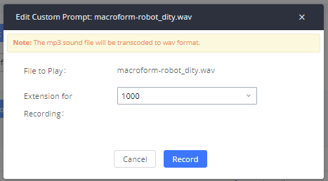
- Answer the call and start to record your new music on hold.
- Hangup the call and refresh Music On Hold page then you can listen to the new recorded file.
Voice Prompt
The IPPBX supports multiple languages in Web GUI as well as system voice prompt. Currently, there are 16 languages supported in system voice prompt: English (United States), Arabic, Chinese, Dutch, English (United Kingdom), French, German, Greek, Hebrew, Italian, Polish, Portuguese, Russian, Spanish, Catalan, Swedish and Turkish.
English (United States) and Chinese voice prompts are preloaded in with the IPPBX already. The other languages provided by Grandstream can be downloaded and installed from the IPPBX Web GUI directly. Additionally, users could customize their own voice prompts, package them and upload to the IPPBX.
Language settings for voice prompt can be accessed under Web GUI🡪PBX Settings🡪Voice Prompt🡪Language Settings.
To download and install voice prompt package in different languages from IPPBX Web GUI, click on “Add Voice Prompt Package” button.
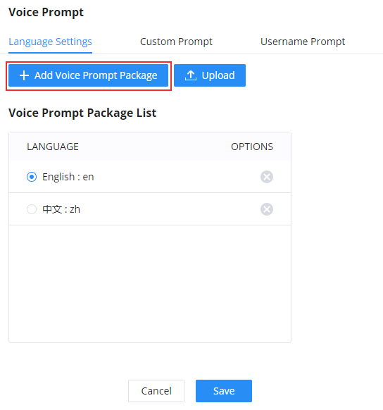
A new dialog window of voice prompt package list will be displayed. Users can see the version number (latest version available V.S. current installed version), package size and options to upgrade or download the language.
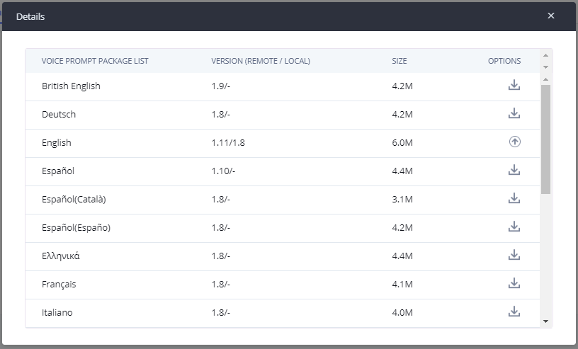
Click on ![]() to download the language to the IPPBX. The installation will be automatically started once the downloading is finished.
to download the language to the IPPBX. The installation will be automatically started once the downloading is finished.
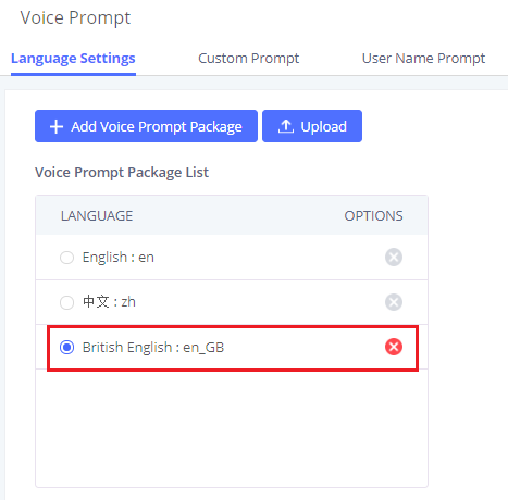
A new language option will be displayed after successfully installed. Users then could select it to apply in the IPPBX system voice prompt or delete it from the IPPBX.
Custom Prompt
On the IPPBX, if the user needs to replace some specific customized prompt, the user can upload a single specific customized prompt from Web GUI🡪PBX Settings🡪Voice Prompt🡪Language Settings and click on “Upload” instead of the entire language pack.
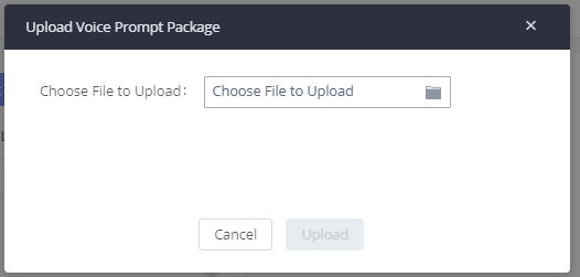
Username Prompt
There are two ways to customize/set new username prompt:
Upload Username Prompt File from Web GUI
- First, Users should have a pre-recorded file respecting the following format:
- PCM encoded / 16 bits / 8000Hz mono.
- In .tar/.tar.gz/.tgz format
- File size under 30M.
- Filename must be set as the extension number with 18 characters max. For example, the recorded file name 1000.wav will be used for extension 1000.
- Go under web GUI PBX Settings 🡪 Voice Prompt 🡪 Username Prompt and click on ”Upload” button.
- Select the recorded file to upload it and press Save and Apply Settings.
- Click on
 to record again the username prompt.
 - Click on to play recorded username prompt.
- Select username prompts and press to delete specific file or select multiple files for deletion using the button ”Delete” .
Record Username via Voicemail Menu
The second option to record username is using voicemail menu, please follow below steps:
- Dial *98 to access the voicemail
- After entering the desired extension and voicemail password, dial “0” to enter the recordings menu and then “3” to record a name.
Another option is that each user can record their own name by following below steps:
- The user dials *97 to access his/her voicemail
- After entering the voicemail password, the user can press “0” to enter the recordings menu and then “3” to record his name.
Call Prompt Tones
SIP Trunk Prompt Tone
Prompt Tone Settings tab has been added to the IPPBX to help users choose which prompt will be played by the IPPBX during call failure, the following voice message responses have been added and can be set to be played for 4XX, 5XX, and 6XX call failures:
- Default for 404 and 604 status codes: “Your call can’t be completed as dialed. Please check the number and dial again.”
- Default for 5xx status codes: “Server error. Please check your device.”
- Default for 403 and 603 status codes: “The call was rejected by the server. Please try again later.”
- Default for all other status codes: “All circuits are busy now. Please try again later.”
Additionally, custom voice messages recorded and uploaded in PBX Settings🡪Voice Prompt🡪Custom Prompt can be used for these failure responses instead of the default messages.
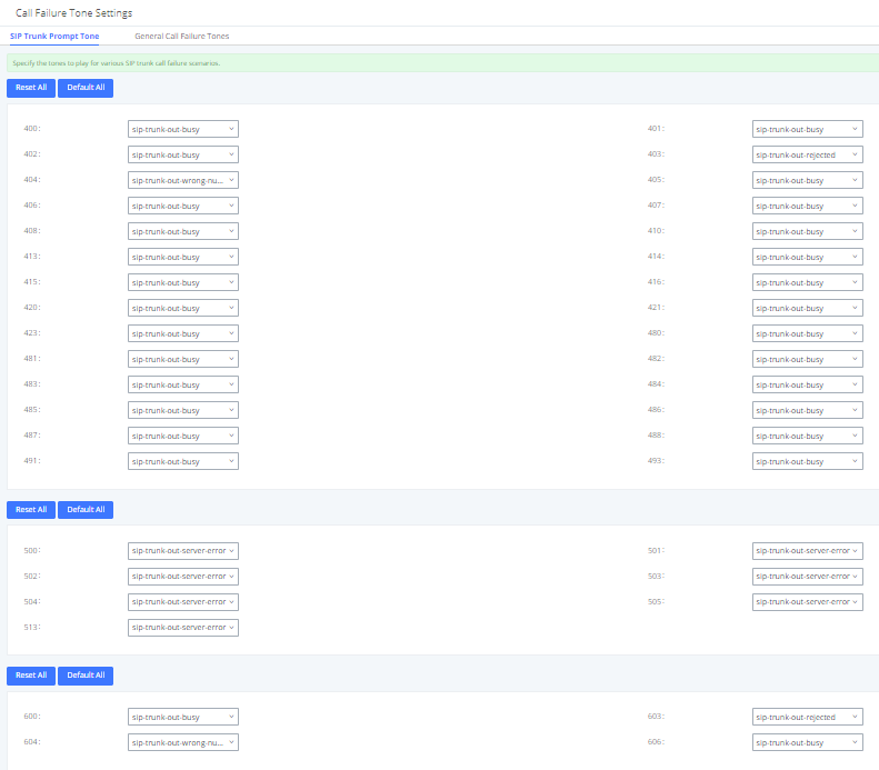
General Call Prompt Tones
Moreover, users also have the possibility to customize the prompt for typical call failure reasons like (no permission to allow outbound calls, busy lines, incorrect number dialed …Etc.).
To customize these prompts user could record and upload their own files under “’PBX Settings 🡪 Voice Prompt 🡪 Custom Prompts” then select each one for specific call failure case under “PBX Settings -> Call Prompt Tones 🡪 General Call Prompt Tones” page as shown on the following figure:
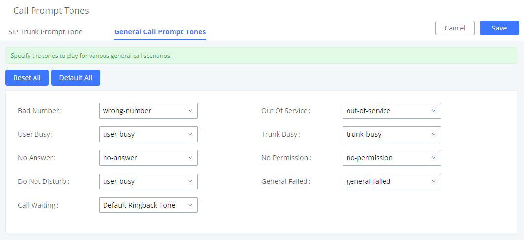
Alert-Info Prompt
The user can change upload the ringtone files which can be used with Alert-info to play various ringtones depending on the configured behaviour. In this setting, the user can view all the ringtones uploaded, play them, download them, or delete them. If the user wishes to upload new ringtones, he/she can click on “Upload” and choose the ringtone files to upload.
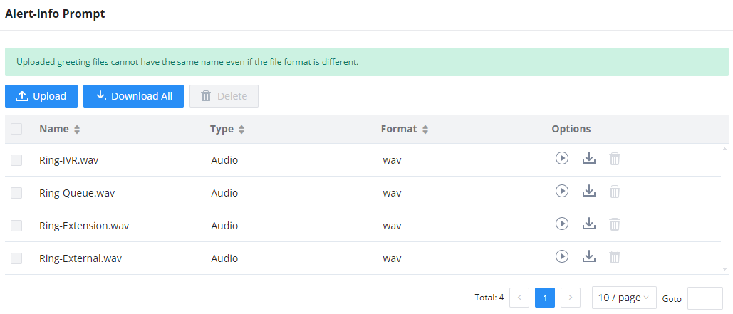
File Manager
Storage Device Manager
IPPBX supports automatic or manual recording of calls and storage of IM chat files. Only recording files and IM files can be stored locally or on the GDMS, meanwhile, video recording files can only be stored on NAS. Local storage means that the files will be stored in the internal memory of the IPPBX. For extra storage capacity the user can plug a USB flash drive or an SD card, the IPPBX will always store in the USB drive first, then the SD card. In case no storage drive is attached, it will automatically start storing the files internally.
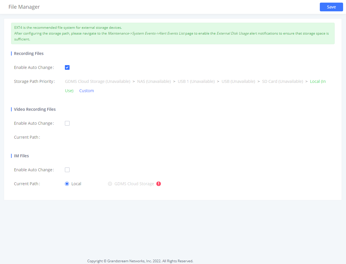
- If “Enable Auto Change” is selected, the files will be automatically saved in the available USB Disk or SD card plugged into the IPPBX. If both USB Disk and SD card are plugged in, the files will be always saved in the USB Disk.
- When “Enable Auto Change” is enabled, the option “Storage Path Priority“will appear. It allows the user to configure the priority of each storage unit in the priority list (The storage on top of the list has the highest priority). The default priority list is GDMS Cloud Storage > NAS > USB 1 > USB > SD Card > Local
- If “Local” is selected, the files will be stored in the internal storage. If a storage drive is inserted, the IPPBX will store the files into the storage drive instead of internal storage. Priority list is USB drive, then SD Card.
- If “GDMS Cloud Storage” is selected, data will no longer be stored locally and if you need to listen to the recording, download the file to the computer side and play it offline.
Once “USB Disk” or “SD Card” is selected, click on “OK”. The user will be prompted to confirm to copy the local files to the external storage device.
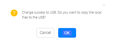
Click on “OK” to continue. The users will be prompted a new dialog to select the categories for the files to be copied over.
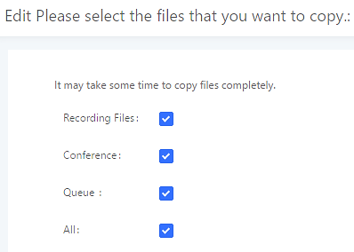
Note
Once a storage device has filled up, the IPPBX will choose the next available storage device based on the Storage Path Priority.
On the IPPBX, users have the following options when select the categories to copy the files to the external device:
- Recording Files: Copy the normal recording files to the external device.
- Conference: Copy the conference recording files to the external device.
- Queue: Copy the call queue recording files to the external device.
- All: Copy all recording files to the external device.
NAS
The IPPBX supports adding and backing up recordings to a network-attached storage (NAS) server. Following table describes NAS settings:
| Enable | Enabled / Disable the NAS recording functionality. |
| Host | Configure the Domain or IP address of the NAS server.Note: Currently, only IP addresses are supported in the Host/IP field. |
| Share Name | Specify the name of the shared folder. |
| Username | Specify the account username to access the NAS server. |
| Password | Configure the account password to access the NAS server. The password can include letters, number, and special characters. |
| Security Mode | Select a security mode based on the server settings to ensure proper connection establishment. The default value is ntlmssp. |
| Status | If configured correctly, the Status field will show “Mounted”, and the newly added NAS server will be shown on the Mounted Netdisk List. Additionally, the NAS will appear as a selectable storage option in the PBX Settings🡪Recording Storage page and CDR🡪Recording Files page. |
SFTP
SFTP integration offers sychronizing files between from the IPPBX to the SFTP server. SFTP is used to synchronize the following data: CDR Records, Recording Files, Voicemail, and Fax.
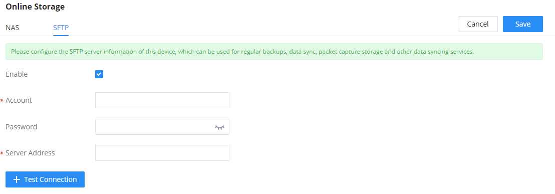
| Enable | Tick this box to enable SFTP integration. |
| Account | Enter the account of the SFTP server. |
| Password | Enter the password of the account of the SFTP server. |
| Server Address | Enter the address of the SFTP server. |
USB Disk/SD Card File Management
This feature allows to browse the SD cards and USB devices which are connected to the GCC device.
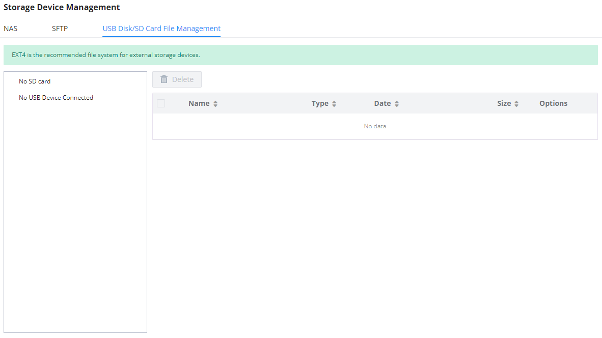
SYSTEM SETTINGS
This section will explain the available system-wide parameters and configuration options on the IPPBX. This includes settings for the following items: General Settings, HTTP server, Security Settings, LDAP Server, Time Settings, and Email Settings.
General Settings
On general settings, the user can configure the Device Name and Enterprise Contact Number.
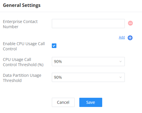
HTTP Server
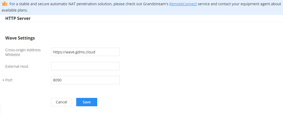
Security Settings
Static Defense
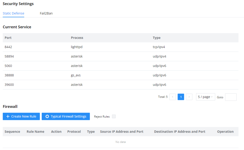
Under Web GUI🡪System Settings🡪Security Settings🡪Static Defense page, users will see the following information:
- Current service information with port, process, and type.
- Typical firewall settings.
- Custom firewall settings.
The following table shows a sample current service status running on the IPPBX.
Port | Process | Type | Protocol or Service |
7777 | Asterisk | TCP/IPv4 | SIP |
389 | Slapd | TCP/IPv4 | LDAP |
6060 | zero_config | UDP/IPv4 | IPPBX zero_config service |
5060 | Asterisk | UDP/IPv4 | SIP |
4569 | Asterisk | UDP/IPv4 | SIP |
38563 | Asterisk | udp/ipv4 | SIP |
10000 | gs_avs | udp/ipv4 | gs_avs |
10001 | gs_avs | udp/ipv4 | gs_avs |
10002 | gs_avs | udp/ipv4 | gs_avs |
10003 | gs_avs | udp/ipv4 | gs_avs |
10004 | gs_avs | udp/ipv4 | gs_avs |
10005 | gs_avs | udp/ipv4 | gs_avs |
10006 | gs_avs | udp/ipv4 | gs_avs |
10007 | gs_avs | udp/ipv4 | gs_avs |
10010 | gs_avs | udp/ipv4 | gs_avs |
10012 | gs_avs | udp/ipv4 | gs_avs |
10013 | gs_avs | udp/ipv4 | gs_avs |
10014 | gs_avs | udp/ipv4 | gs_avs |
10015 | gs_avs | udp/ipv4 | gs_avs |
10018 | gs_avs | udp/ipv4 | gs_avs |
10019 | gs_avs | udp/ipv4 | gs_avs |
10020 | gs_avs | udp/ipv4 | gs_avs |
6066 | Python | udp/ipv4 | python |
3306 | Mysqld | tcp/ipv4 | mysqld |
45678 | Python | udp/ipv4 | python |
8439 | Lighttpd | tcp/ipv4 | HTTP |
8088 | asterisk | tcp/ipv4 | SIP |
8888 | Pbxmid | tcp/ipv4 | pbxmid |
25 | Master | tcp/ipv4 | master |
636 | Slapd | tcp/ipv4 | SLDAP |
4569 | asterisk | udp/ipv6 | SIP |
42050 | asterisk | udp/ipv6 | SIP |
7681 | Pbxmid | tcp/ipv4 | pbxmid |
For typical firewall settings, users could configure the following options on the IPPBX.
Ping Defense Enable | If enabled, ICMP response will not be allowed for Ping requests. The default setting is disabled. To enable or disable it, click on the check box for the LAN or WAN (IPPBX) interface. |
Allows the IPPBX to handle excessive amounts of SYN packets from one source and keep the web portal accessible. There are two options available and only one of these options may be enabled at one time.
SYN Flood Defense will limit the amount of SYN packets accepted by the IPPBX from one source to 10 packets per second. Any excess packets from that source will be discarded. | |
Ping-of-Death Defense Enable | Enable to prevent Ping-of-Death attack to the device. The default setting is disabled. To enable or disable it, click on the check box for the LAN or WAN (IPPBX) interface. |
Under “Custom Firewall Settings”, users could create new rules to accept, reject or drop certain traffic going through the IPPBX. To create a new rule, click on the “Create New Rule” button and a new window will pop up for users to specify rule options.
Right next to the “Create New Rule” button, there is a checkbox for the option “Reject Rules”. If it is checked, all the rules will be rejected except the firewall rules listed below. In the firewall rules, only when there is a rule that meets all the following requirements, the option “Reject Rules” will be allowed to check:
- Action: “Accept”
- Type “In”
- The destination port is set to the system login port (e.g., by default 8089)
- The protocol is not UDP
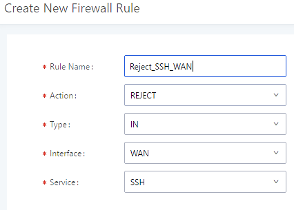
Rule Name | Specify the Firewall rule name to identify the firewall rule. |
Action | Select the action for the Firewall to perform.
|
Type | Select the traffic type.
If selected, users will need to specify the network interface “LAN” or “WAN” (for IPPBX) for the incoming traffic.
|
Interface | Select the interface to use the Firewall rule. |
Service | Select the service type.
If “Custom” is selected, users will need to specify Source (IP and port), Destination (IP and port), and Protocol (TCP, UDP, or Both) for the service. Please note if the source or the destination field is left blank, it will be used as “Anywhere”. |
Source IP Address and Port | Configure a source subnet and port. If set to “Anywhere” or left empty, traffic from all addresses and ports will be accepted. A single port or a range of ports can be specified (e.g., 10000, 10000-20000). |
Destination IP Address and Port | Configure a destination subnet and port. If set to “Anywhere” or left empty, traffic can be sent to all addresses and ports. A single port or a range of ports can be specified (e.g., 10000, 10000-20000). |
Protocol | Select the protocol for the rule to be used. |
Firewall Rule Settings
Save the change and click on the “Apply” button. Then submit the configuration by clicking on “Apply Changes” on the upper right of the web page. The new rule will be listed at the bottom of the page with sequence number, rule name, action, protocol, type, source, destination, and operation. More operations are below:
-
Click on
to edit the rule.
-
Click on
to delete the rule.
Fail2Ban
Fail2Ban feature allows to control the attempts to register to the IPPBX using a SIP endpoint, it allows a set number of attempts. If the client fails to provide the correct authentication ID and the authentication password, the client’s IP address will be blacklist for a time duration which can be configured on the same page.
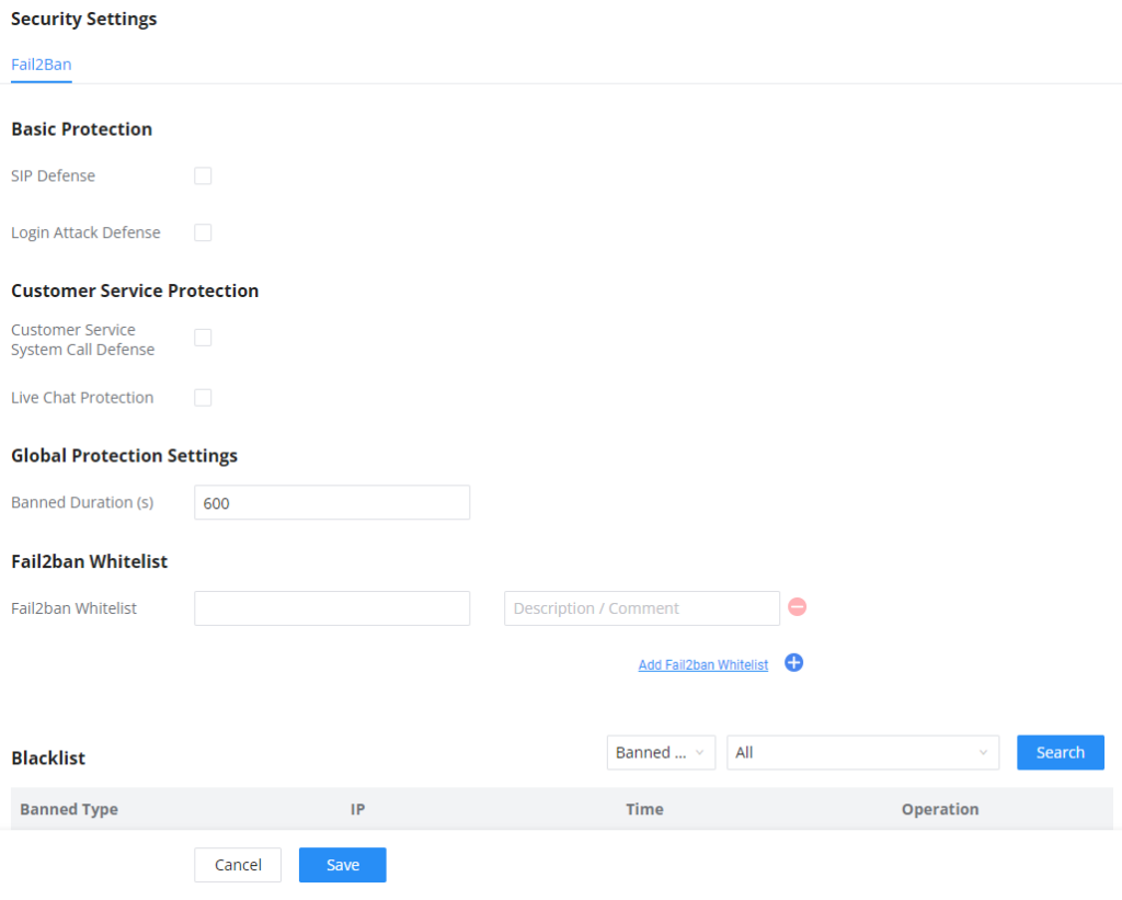
LDAP Server
The IPPBX has an embedded LDAP/LDAPS server for users to manage the corporate phonebook in a centralized manner.
- By default, the LDAP server has generated the first phonebook with PBX DN “ou=pbx,dc=pbx,dc=com” based on the IPPBX user extensions already.
- Users could add new phonebook with a different Phonebook DN for other external contacts. For example, “ou=people,dc=pbx,dc=com”.
- All the phonebooks in the IPPBX LDAP server have the same Base DN “dc=pbx,dc=com”.
Term Explanation:
cn= Common Name
ou= Organization Unit
dc= Domain Component
These are all parts of the LDAP Data Interchange Format, according to RFC 2849, which is how the LDAP tree is filtered.
If users have the Grandstream phone provisioned by the IPPBX, the LDAP directory will be set up on the phone and can be used right away for users to access all phonebooks.
Additionally, users could manually configure the LDAP client settings to manipulate the built-in LDAP server on the IPPBX. If the IPPBX has multiple LDAP phonebooks created, in the LDAP client configuration, users could use “dc=pbx,dc=com” as Base DN to have access to all phonebooks on the IPPBX LDAP server, or use a specific phonebook DN, for example “ou=people,dc=pbx,dc=com”, to access to phonebook with Phonebook DN “ou=people,dc=pbx,dc=com ” only.
IPPBX can also act as an LDAP client to download phonebook entries from another LDAP server.
To access the LDAP server and client settings, go to Web GUI🡪Settings🡪LDAP Server.
LDAP Server Configurations
The following figure shows the default LDAP server configurations on the IPPBX.
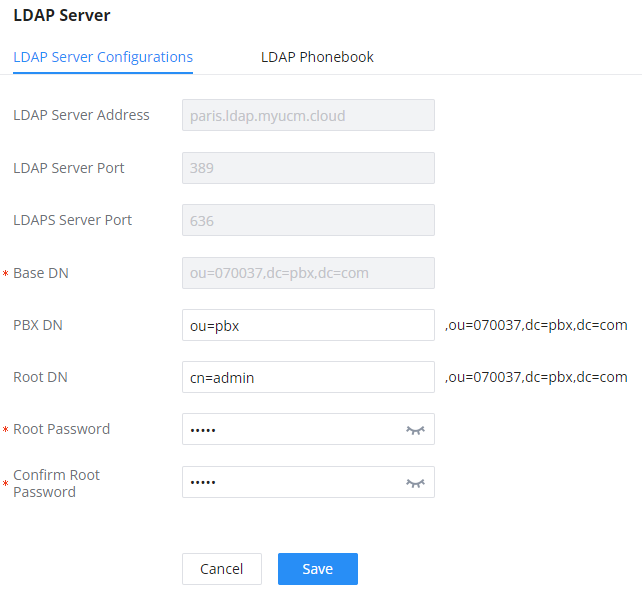
The IPPBX LDAP server supports anonymous access (read-only) by default. Therefore, the LDAP client does not have to configure a username and password to access the phonebook directory. The “Root DN” and “Root Password” here are for LDAP management and configuration where users will need to provide for authentication purposes before modifying the LDAP information.
The default phonebook list in this LDAP server can be viewed and edited by clicking on/for the first phonebook under LDAP Phonebook.
The IPPBX supports secure LDAP (LDAPS) where the communication is encrypted and secure.

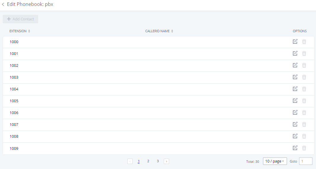
LDAP Phonebook
Users could use the default phonebook, edit the default phonebook, add new phonebook, import phonebook on the LDAP server as well as export phonebook from the LDAP server. The first phonebook with default phonebook dn “ou=pbx,dc=pbx,dc=com” displayed on the LDAP server page is for extensions in this PBX. Users cannot add or delete contacts directly. The contacts information will need to be modified via Web GUI🡪Extension/Trunk🡪Extensions first. The default LDAP phonebook will then be updated automatically.
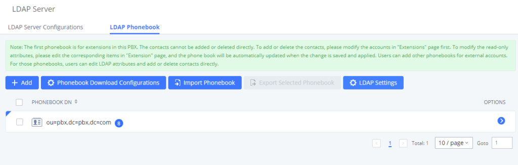
- Add new phonebook
A new sibling phonebook of the default PBX phonebook can be added by clicking on “Add” under “LDAP Phonebook” section.
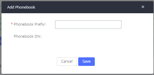
Configure the “Phonebook Prefix” first. The “Phonebook DN” will be automatically filled in. For example, if configuring “Phonebook Prefix” as “people”, the “Phonebook DN” will be filled with “ou=people,dc=pbx,dc=com”.
Once added, users can select ![]() to edit the phonebook attributes and contact list (see figure below) or select
to edit the phonebook attributes and contact list (see figure below) or select ![]() to delete the phonebook.
to delete the phonebook.
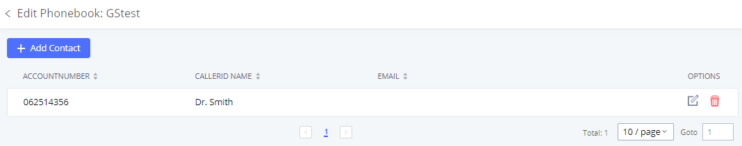
- Import phonebook from your computer to LDAP server
Click on “Import Phonebook” and a dialog will prompt as shown in the figure below.
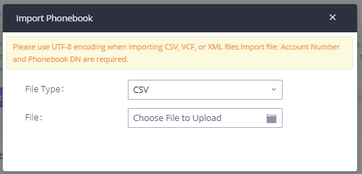
The file to be imported must be a CSV, VCF or XML file with UTF-8 encoding. Users can open the file with Notepad and save it with UTF-8 encoding.
Here is how a sample file looks like. Please note “Account Number” and “Phonebook DN” fields are required. Users could export a phonebook file from the IPPBX LDAP phonebook section first and use it as a sample to start with.
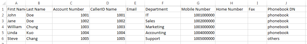
The Phonebook DN field is the same “Phonebook Prefix” entry as when the user clicks on “Add” to create a new phonebook. Therefore, if the user enters “phonebook” in “Phonebook DN” field in the CSV file, the actual phonebook DN “ou=phonebook,dc=pbx,dc=com” will be automatically created by the IPPBX once the CSV file is imported.
In the CSV file, users can specify different phonebook DN fields for different contacts. If the phonebook DN already exists on the IPPBX LDAP Phonebook, the contacts in the CSV file will be added into the existing phonebook. If the phonebook DN does not exist on the IPPBX LDAP Phonebook, a new phonebook with this phonebook DN will be created.
The sample phonebook CSV file in above picture will result in the following LDAP phonebook in the IPPBX.
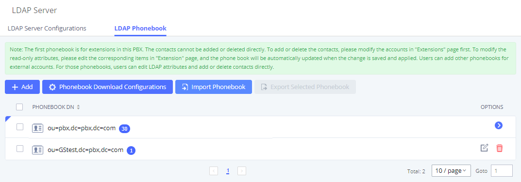
As the default LDAP phonebook with DN “ou=pbx,dc=pbx,dc=com” cannot be edited or deleted in LDAP phonebook section, users cannot import contacts with Phonebook DN field “pbx” if existed in the CSV file.
- Export phonebook to your computer from the IPPBX LDAP server
Select the checkbox for the LDAP phonebook and then click on “Export Selected Phonebook” to export the selected phonebook. The exported phonebook can be used as a record or a sample CSV, VFC or XML file for the users to add more contacts in it and import to the IPPBX again.
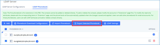
LDAP Settings
Prerequisites to support contacts sync-up to IP Phones, IPPBX needs to support the following:
- If Cloud IM is enabled, IPPBX can send remote IPPBX’s contacts to each end device.
- Contacts from remote IPPBX can be synced by Cloud IM or LDAP sync via trunk. The contacts data must be complete and consistent.
- If Cloud IM is enabled, the contacts sent from IPPBX to end device should integrate Cloud IM contacts.
- If Cloud IM is disabled, the contacts sent from IPPBX to end device should only contain contacts on the IPPBX.
To support contacts sync-up to Wave, it allows Wave to obtain enterprise contacts from Cloud IM or LDAP. On IPPBX SIP peer trunk, if LDAP sync is enabled, end point can obtain remote IPPBX extensions’ info via LDAP. Also, it will allow configuring whether to sync up LDAP contacts on Wave so that Wave doesn’t receive duplicate contacts info.
Under IPPBX webUI🡪 System Settings🡪 LDAP Server, click on “LDAP Settings”, option “Wave enable LDAP phonebook” is available for configuration. If enabled, all Wave users on this IPPBX will display LDAP contacts. Otherwise, it will not display.
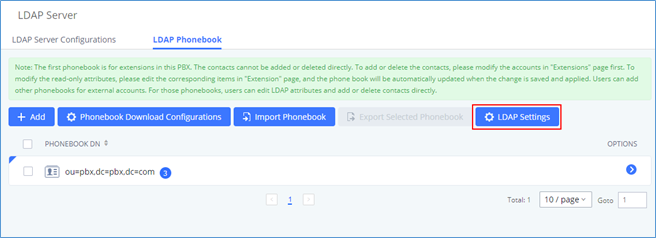
Please note the LDAP contacts displayed on Wave will exclude the duplicate contacts from Cloud IM.
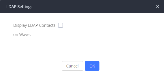
LDAP Client Configuration
The configuration on LDAP client is useful when you use other LDAP servers. Here we provide an example on how to configure the LDAP client on the IPPBX.
Assuming the remote server base dn is “dc=pbx,dc=com”, configure the LDAP client as follows:
LDAP Client Type
Field | Description |
PMS Module | Users can select the desired PMS module from the drop-down list.
|
Wakeup Prompt | A customized prompts that can be played when the wakeup call is answered. To customize it please navigate to PBX Settings 🡪 Voice Prompt 🡪 Custom Prompt |
Username | This username is used to authenticate into the PMS API. |
Password | This password is used to autheticate into the PMS API. |
Back Up Voicemail Recordings | Back up voicemail recordings to external storage after check-out. |
Automatically Clear Wakeup Calls | Scheduled wakeup calls for rooms can be cleared upong checking in or checking out.
|
Automatically Clear Wave Chat History | If enabled, room Wave chat history will be automatically cleared upon check-in or check-out. |
Automatically Reset User/Wave Password | If enabled, the User/Wave password of the room extension will be automatically reset to a random password upon check-out. |
The IPPBX can automatically update the phonebook, by configuring the ‘LDAP Automatic Update Cycle’. Available options are: 1 day/2days/7 days. It is set to ‘None’ by default.
The following figure gives a sample configuration for IPPBX acting as a LDAP client.
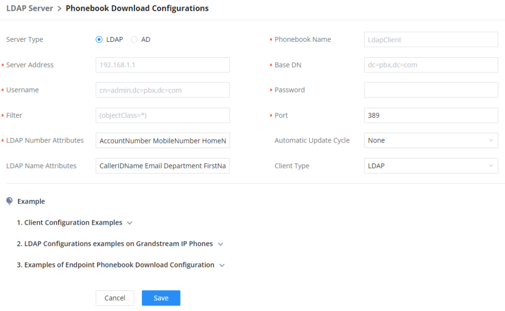
Parameter | Description |
Base DN | Specifies the location in the directory where the search is requested to begin. By default it’s “dc=pbx,dc=com”. |
PBX DN | Specifies the location in the directory where the search for PBX entry is requested to begin. It narrows the search scope and decreases directory lookup time. By default it’s “ou=pbx,dc=pbx,dc=com”. |
Root DN | Specifies the location in the directory where the search for the admin user entry is requested to begin. It narrows the search scope and decreases directory lookup time. By default it’s “cn=admin,dc=pbx,dc=com” |
Root Password | Defines the root password for authentication. By default, is “admin”. |
Confirm Root Password | Confirms the root password for authentication. |
LDAP Cert | Certificate for LDAPS connections. Uploaded files must be less than 2MB in file size and will be automatically renamed to “server.crt”. |
LDAP Private Key | Private key for LDAPS connections. Uploaded files must be less than 2MB in file size and will automatically be renamed to “private.key”. |
LDAP CA Cert | Root certificate for LDAPS connections. Uploaded files will be automatically renamed to “server.ca”. |
To configure Grandstream IP phones as the LDAP clients for IPPBX, please refer to the following example:
- Server Address: The IP address or domain name of the IPPBX
- Base DN: dc=pbx,dc=com
- Username: cn=admin,dc=pbx,dc=com
- Password: admin (by default)
- LDAP Name Attribute: CallerIDName Email Department FirstName LastName
- LDAP Number Attribute: AccountNumber MobileNumber HomeNumber Fax
- LDAP Number Filter: (AccountNumber=%)
- LDAP Name Filter: (CallerIDName=%)
- LDAP Display Name: AccountNumber CallerIDName
- LDAP Version: If existed, please select LDAP Version 3
- Port: 389
The following figure shows the configuration information on a Grandstream GXP2170 to successfully use the LDAP server as configured in [LDAP Server Configurations].
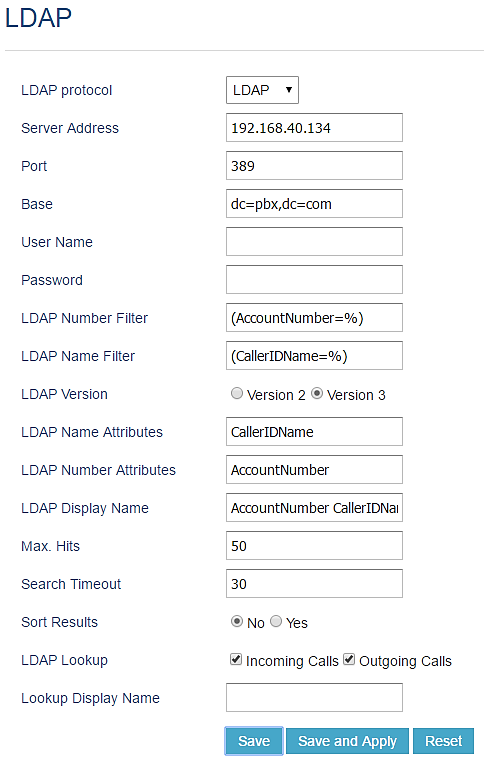
Time Settings
The current system time on the IPPBX can be found under Web GUI🡪System Status🡪Dashboard🡪PBX Status.
Office Time
On the IPPBX, the system administrator can define “office time” which can be used to configure time condition for extension call forwarding and inbound rules. To configure office time, log in to the Web GUI, enter the System Settings🡪Time Settings🡪Office Time, and click the “Add” button to see the following configuration page.
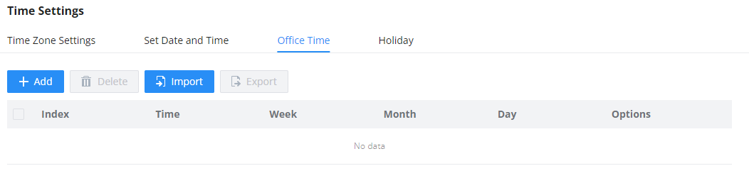
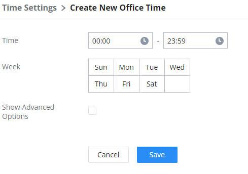
Start Time | Configure the start time for office hour. |
End Time | Configure the end time for office hour |
Week | Select the workdays in one week. |
Show Advanced Options | Check this option to show advanced options. Once selected, please specify “Month” and “Day” below. |
Month | Select the months for office time. |
Day | Select the workdays in one month. |
Select “Start Time”, “End Time” and the day for the “Week” for the office time. The system administrator can also define month and day of the month as advanced options. Once done, click on “Save” and then “Apply Change” for the office time to take effect. The office time will be listed in the web page as the figure shows below.
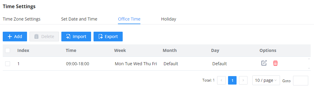
-
Click on
to edit the office time.
-
Click on
to delete the office time.
- Click on “Delete” to delete multiple selected office times at once.
Holiday
On IPPBX, the system administrator can define “holidays” which can be used to configure time condition for extension call forwarding and inbound rules. To configure office time, log in to the Web GUI, enter the System Settings🡪Time Settings🡪Holiday, and click the “Add” button to see the following configuration page.
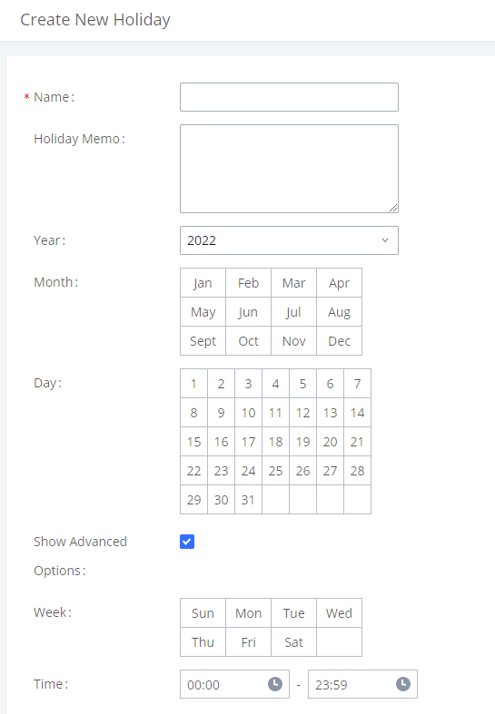
Name | Specify the holiday name to identify this holiday. |
Holiday Memo | Create a note for the holiday. |
Month | Select the month for the holiday. |
Year | Select the Year for the holiday. Note: In the "Year" option, select "All" to set annual fixed holiday information. |
Day | Select the day for the holiday. |
Show Advanced Options | Check this option to show advanced options. If selected, please specify the days as holiday in one week below. |
Week | Select the days as holiday in one week. |
Time | Select the time on which the holiday starts. |
Enter holiday “Name” and “Holiday Memo” for the new holiday. Then select “Month”, “Day” and the exact “Hour”. The system administrator can also define days in one week as advanced options. Once done, click on “Save” and then “Apply Change” for the holiday to take effect. The holiday will be listed in the web page as the figure shows.
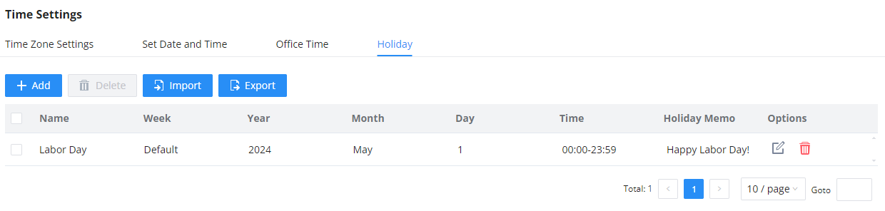
-
Click on
to edit the holiday.
-
Click on
to delete the holiday.
- Click on “Delete” to delete multiple selected holidays at once.
SNMP
SNMP integration in the IPPBX allows the administrator to monitor the components of the IPPBX remotely. SNMP is a useful integration to have a centralized monitoring dashboard that shows all the devices on your network, with that status of internal component. To configure the SNMP integration, please navigate to the web GUI of the IPPBX, then go to System Settings → SNMP → SNMP Settings
SNMP Settings
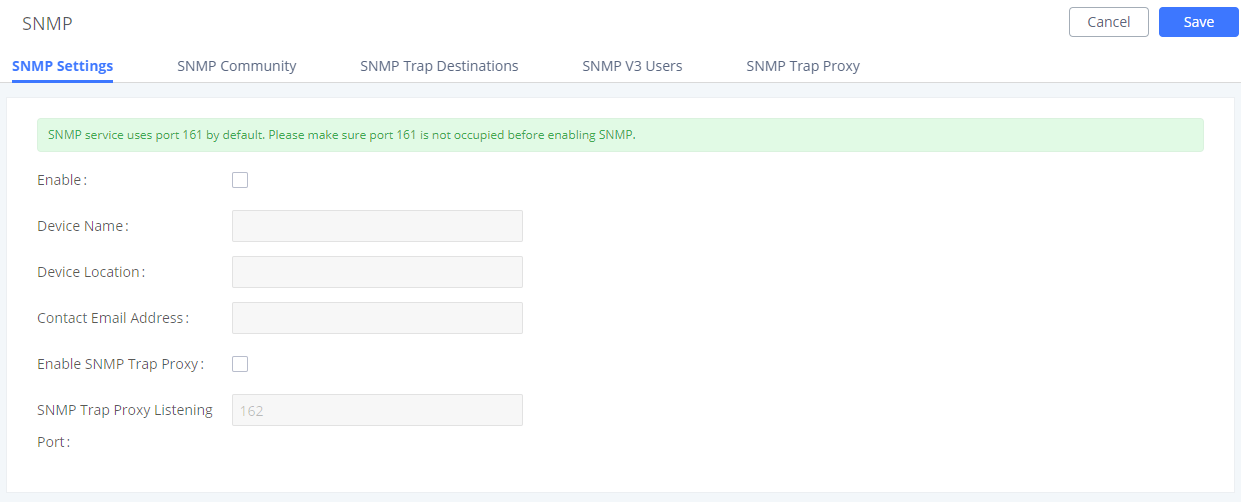
Enable | Tick this box to enable SNMP. |
Device Name | Enter the device name. |
Location | Enter the location. |
Contact Email Address | Enter the email address used to send the SNMP alerts to. |
Enable SNMP Trap Proxy | Tick this box to enable a proxy for SNMP Trap. |
SNMP Trap Proxy Listening Port | The port number on which the SNMP Trap Proxy is listening on. |
SNMP Community
You can also create SNMP communities and affect a certain level of access. An SNMP community is a group created to aggregate many management stations. The community name is used to authenticate and identify these machines in the NMS (Network Management System).
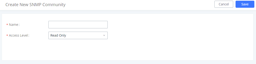
Name | Enter a name for the community |
Access Level | Select an access level:
|
SNMP Traps Destination
SNMP Traps is a very useful feature when there are many network components to manage. Instead of sending requests to all the machines in the network in order to view their SNMP logs risking slowing down or bringing the network to a complete halt, SNMP Traps can be configured so these machines can send unrequested messages to the manager to notify it about critical events and general failures.
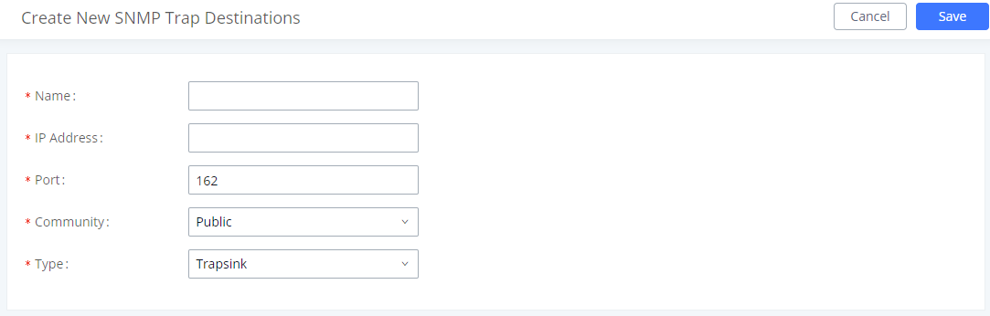
Name | Enter a name of your SNMP Trap destination. |
IP Address | Enter the SNMP Trap destination's IP address. |
Port | Enter the port of the SNMP Trap destination. |
Community | Select the community that you want |
Type | Select the type of SNMP:
|
SNMP Version 3
IPPBX also supports SNMP v3 in case the system administrator decides to add more security to the monitoring process. SNMP v3 is a very good solution to monitor devices that interface directly with Internet. SNMP v3 offers more security than its predecessors by hashing the authentication information, encrypting the SNMP messages exchanged between the managed devices and the network management system which prevent eavesdropping. Also, it prevents any data tampering which protects the integrity of the data exchanged.
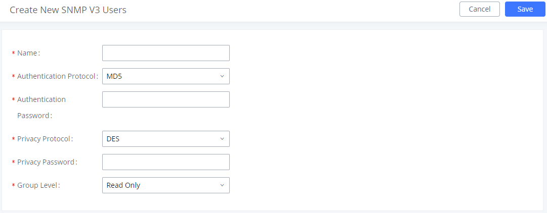
SNMP Trap Proxy
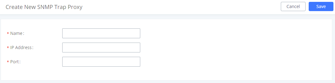
Name | Enter a name for the proxy server. |
IP Address | Enter the proxy server's IP address. |
Port | Enter the proxy server's port. |
TR-069
TR-069 allows remote configuration of the IPPBX. The administrator can use TR-069 to manage multiple IPPBXs at the same time which reduces the time spent on configuring each IPPBX.
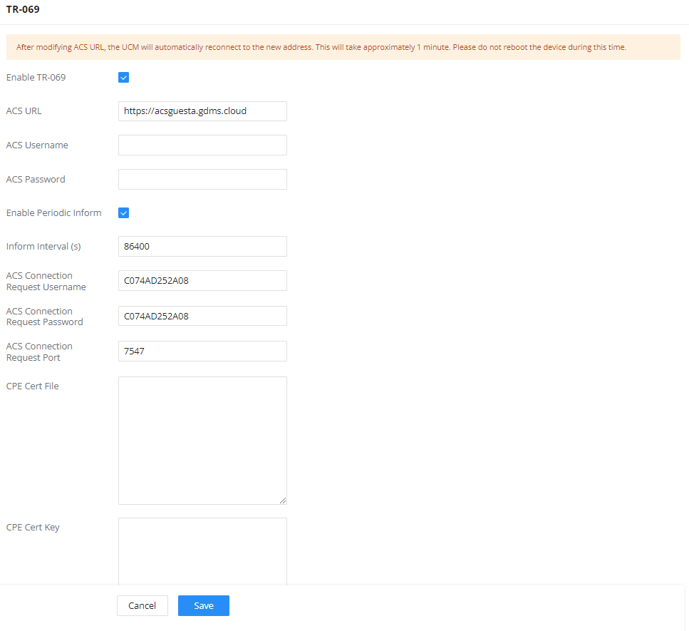
To configure TR-069 on Grandstream devices, set the following parameters:
| Parameter | Description |
|---|---|
Enable TR-069 | Toggle it on to enable TR-069. It is enabled by default |
ACS URL | URL for TR-069 Auto Configuration Servers (ACS), e.g., http://myacs.grandstream.com |
TR-069 Username | ACS username for TR-069 must be the same as in the ACS configuration. |
TR-069 Password | ACS password for TR-069 must be the same as in the ACS configuration. |
Periodic Inform Enable | Enables periodic inform. If set to Yes, the device will send inform packets to the ACS. |
Periodic Inform Interval | A periodic time when IPPBX will send inform packets to TR-069 ACS server. This option is specified in seconds. |
ACS Connection Request Username | The username for the ACS to connect to IPPBX. |
ACS Connection Request Password | The password for the ACS to connect to IPPBX. |
Connection Request Port | Port for incoming connection requests. The default value is 7547. |
CPE Cert File | The Cert file for IPPBX to connect to the ACS via SSL. |
CPE Cert Key | The Cert key for IPPBX to connect to the ACS via SSL. |
CONTACTS
Address book management is under IPPBX web UI->Maintenance, and it has two sections “Contact Management” and “Department management”.
Contact Management
Contact management page displays extension contacts and external contacts information.
- Extension contacts
Extension contacts page shows all the extensions that has “Sync Contact” option enabled in extension settings page. The extension contacts here can be edited or deleted individually or in batch. No new extension contact can be added directly from this page. If an extension contact is deleted from this page, “Sync Contact” option is disabled from this extension. This will not delete the extension from IPPBX.
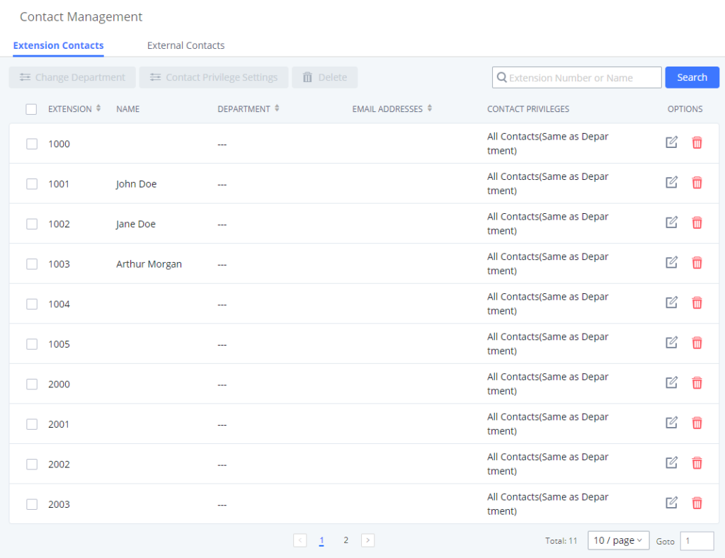
Click Edit icon to configure name, department, email address and etc for each extension contact.
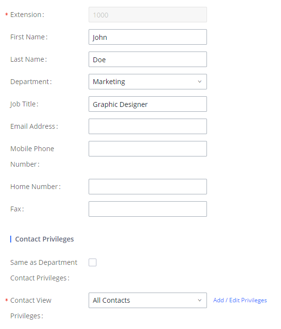
- External contacts
On external contacts page, the admin can create single external contact, import contacts in batch, edit contacts, delete contacts and export contacts.
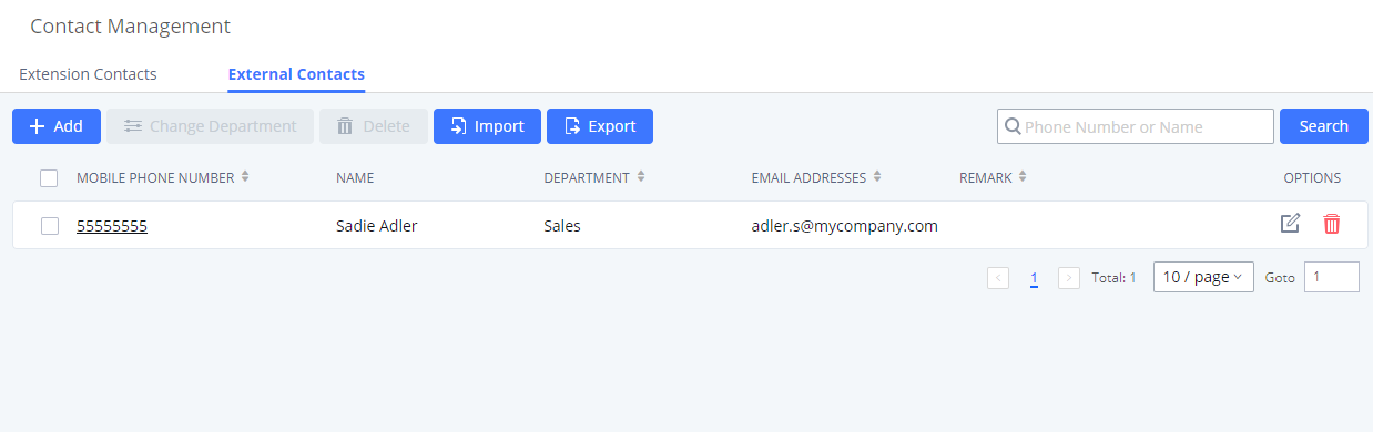
Click on “Export” icon, a CSV format file will be generated with the current external contacts.
Click on “import” icon, then follow the steps below to add external contacts in batch:
- Step 1: For option “On Duplicate External Contacts”, select whether to skip duplicate contact on the imported CSV file or update the duplicate IPPBX contact with the information in the CSV.
- Step 2: Choose file from local PC to upload.
- Step 3: Click on “Upload”.
- Step 4: Click on “Apply” to complete importing external contacts.
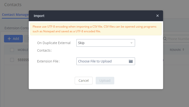
Department Management
Departments are organizational units that allows organizing extensions within groups that specify the specialty of a the extension owners within a company. This makes finding contacts easier within the IPPBX contact books.
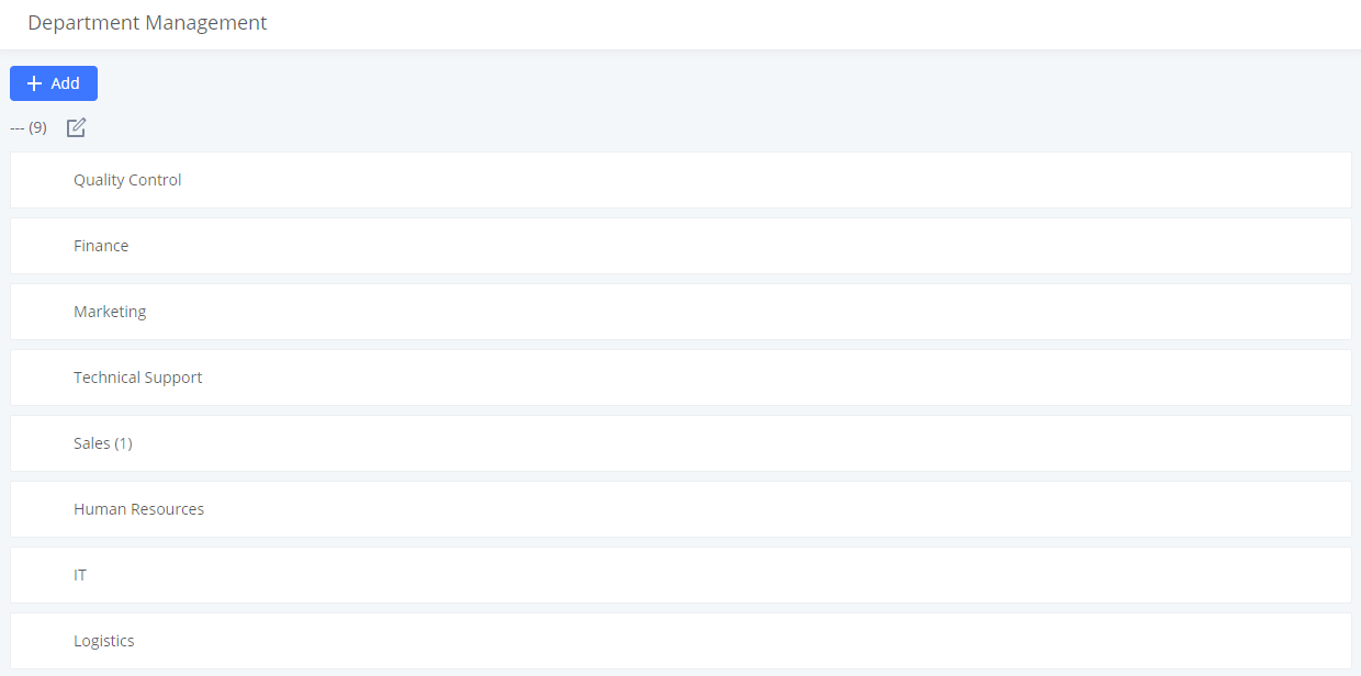
Click on “Add” to create a new department. Configure the department name and select the superior department. By default the superior department is the root directory. If the IPPBX has cloud IM configured, the root directory will be the department in cloud IM.
On the department list:
- Click on
 to create sub department.
 - Click on
 to add member to the department.
 - Click on
 to edit the department.
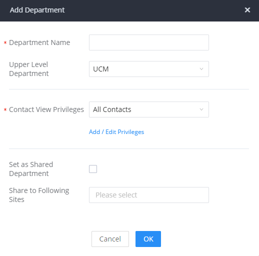
If the IPPBX has Cloud IM enabled and configured, the following options will be available:
- Set as Shared Department: Toggles the shared status of the department. If there are existing cross-server members in this department, this option will be grayed out.
- Share to Following Sites: Select the sites (servers) to that will be allowed to move their extensions in and out of the shared deparmtent.
- Apply Settings to Sub-Level Departments: Only available when editing an exisiting deparmtent. Apply the same sharing settings to its sub-department. If a department has sharing enabled and is configured to be shared with specific sites, its sub-department will also have sharing enabled and be shared with the same sites.
Shared departments can be distinguished by an icon next to their name.
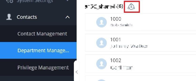
There are 3 potential marks in the center of that icon that represent the permission level that the current IPPBX has for that site
 : The + symbol indicates that the current IPPBX is the creator of the shared department. It has full management priviliges over it, which include the ability to edit it, delete it, add sub-departments under it, add its own extensions to it and remove any extensions from it, including extensions from other servers.
- : The checkmark symbol indicates that the department was shared to the current IPPBX has been authorized to move its own extensions in and out of department.
- : No symbol indicates that the department is from a IPPBX that is under the same Cloud IM account as the current IPPBX, but it has not been shared to the current IPPBX for management. The current IPPBX can only view this shared department and its members but cannot interact with it unless the shared depratment has the current IPPBX’s extensions as members. In this case, the current IPBX can still remove members from the shared department.
If a IPPBX with a shared depratment no longer wants to use CloudIM, it must first do the following:
- If there are no cross-server memebers in its shared departments, it must set them as local departments and assign new parent departments to them.
- If there are existing cross-server members in its shared departments, it must assign the shared departments to another site for management.
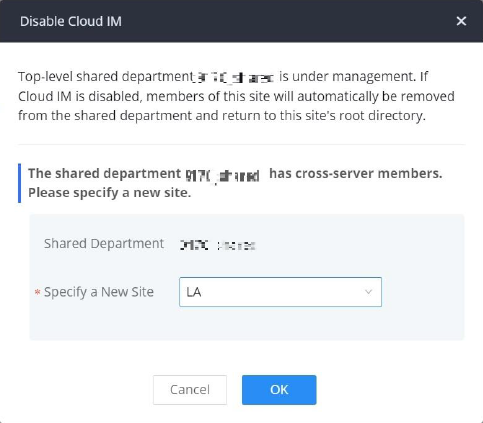
If the IPPBX re-enables Cloud IM, it will not reclaim ownership of its original shared departments.
Shared Departments
Share departmens offer a centralized way for administrators to manage departments and members across multiple servers using the same Cloud IM account. To get started, make sure that the IPPBX has Cloud IM enabled and configured. Then, navigate to Contacts → Department Management, then add/edit a specific department.
Tick the option Set as Shared Department, then select the sites to which the department will be shared. If the user wishes to apply the same sharing settings to the departments nested under the parent department, please tick the option Apply Settings to Sub-Level Departments.
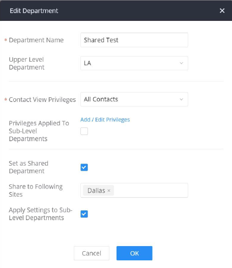
Privilege Management
The user can configure custom privileges other than the default ones (All contacts, Departments and sub-departments contacts). These custom privileges allow more flexible ways of allowing contacts to view all or specific contacts from other departments.
IPPBX admin can add or edit Privilege Management; under IPPBX web UI🡪Contacts Privilege Management, there are 2 default privileges:
- Visible to all contacts.
- Only the contact person’s department and sub-department contacts are visible.
When Cloud IM is enabled on the IPPBX, a third privilege is created:
- Local Contacts: Restricts the contacts shown to the contacts of the local IPPBX.
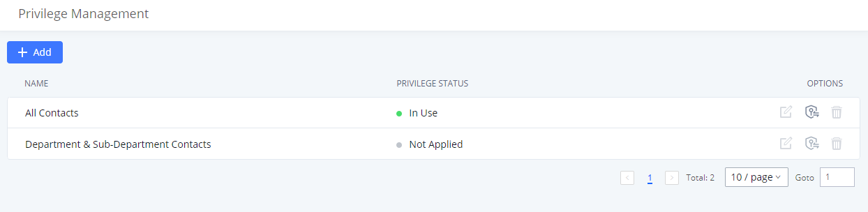
DEVICE MANAGEMENT
Onsite Meeting
For workplaces that require employees to return to physical offices for work, Grandstream IPPBX offers the Onsite Meetings feature, a new way to stay organized and keep up-to-date with in-person meetings. This feature allows administrators to create and manage onsite meeting rooms, specify meeting room locations, schedule meetings, and add conferencing equipment. The new feature can be found under the Device Management > Onsite Meeting page. The first page that appears is the Scheduled Meetings page and tab page, which provide an overview of all created meeting rooms. It provides information about the rooms’ meeting schedules for the day, their locations, their member capacity, and their equipment.
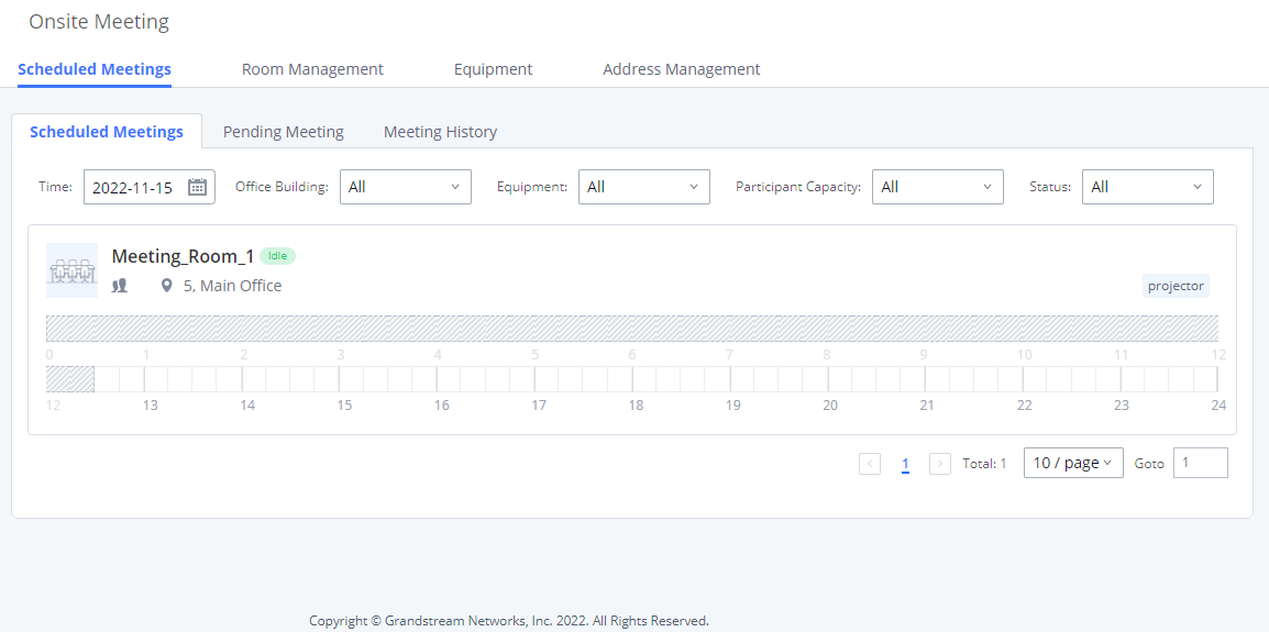
The Pending Meeting tab and Meeting History tab show detailed information about upcoming meetings and previous meetings respectively. From the Pending Meeting tab, users can delete upcoming meetings and extend the duration of ongoing meetings. The Meeting History tab will display the last 6 months of onsite meetings.
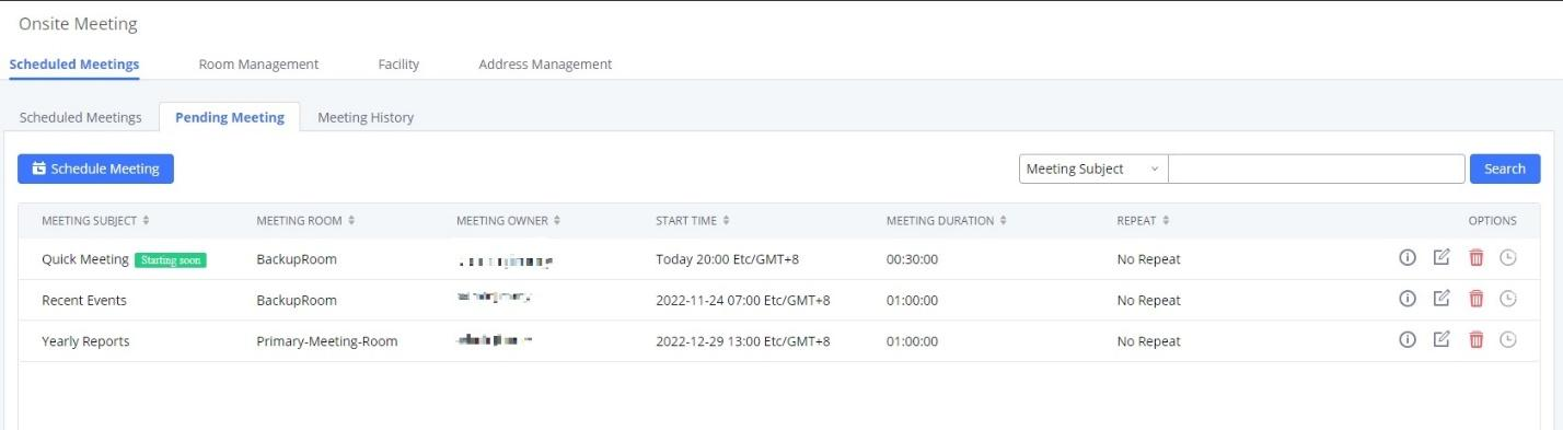
MAINTENANCE
User Management
Custom Privilege
Four privilege levels are supported:
- Super Administrator
- This is the highest privilege. Super Admin can access all pages on IPPBX Web GUI, change configuration for all options and execute all the operations.
- Super Admin can create, edit, and delete one or more users with “Admin” privilege
- Super Admin can edit and delete one or more users with “Consumer” privilege
- Super Admin can view operation logs generated by all users.
- By default, the user account “admin” is configured with “Super Admin” privilege and it is the only user with “Super Admin” privilege. The Username and Privilege level cannot be changed or deleted.
- Super Admin could change its own login password on Web GUI🡪Maintenance🡪Login Settings page.
- Super Admin could view operations done by all the users in Web GUI🡪Maintenance🡪User Management🡪Operation Log
- Administrator
- Users with “Admin” privilege can only be created by “Super Admin” user.
- “Admin” privilege users are not allowed to access the following pages:
Maintenance🡪Upgrade
Maintenance🡪Cleaner
Maintenance🡪Reset/Reboot
Settings🡪User Management🡪Operation Log
- “Admin” privilege users cannot create new users for login.
Note: By default, administrator accounts are not allowed to access backup menu, but this can be assigned to them by editing the option “Maintenance 🡪 User Management 🡪 Custom Privilege” then press ![]() to edit the “Admin” account and include backup operation permission for these types of users.
to edit the “Admin” account and include backup operation permission for these types of users.
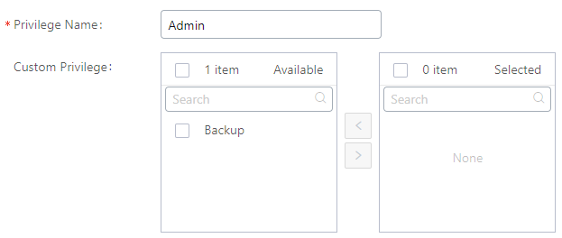
- Consumer
- A user account for Web GUI login is created automatically by the system when a new extension is created.
- The user could log in the Web GUI with the extension number and password to access user information, extension configuration, CDR of that extension, personal data, and Other Features. For more details; please refer to https://documentation.grandstream.com/knowledge-base/user-portal/.
- The SuperAdmin user can click on on the “General_User” in order to enable/disable the custom privilege from deleting their own recording files, changing SIP credentials, and disabling voicemail service in their user portal account.
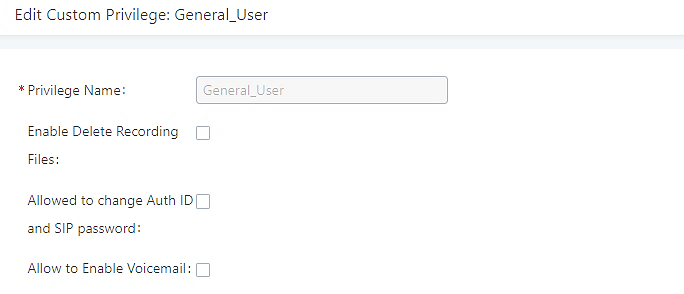
- Custom Privilege
The Super Admin user can create users with different privileges.
- API Configuration
- Backup
- Callback
- Call Queue
- Queue Statistics
- Queue Recordings
- CDR Recordings
- CDR Records
- CDR Statistics
- Dial By Name
- DISA
- Emergency Calls
- Event List
- Extensions
- Extension Groups
- Outbound Routes
- Inbound Routes
- Fax/T.38
- Fax Sending
- Feature Codes
- IVR
- Paging/Intercom
- Parking Lot
- Pickup Groups
- PMS – Wakeup Service
- Ring Groups
- Restrict Calls
- SCA
- Speed Dial
- System Status
- System Events
- LDAP Server
- Time Settings
- Multimedia Meeting
- Voicemail
- Voice Prompt
- Schedule Call
- PMS – Wakeup Service
- Zero Config
- Announcement
- RemoteConnect
Log into the GCC device as super admin and go to Maintenance🡪User Management🡪Custom Privilege, create privilege with customized available modules.
When you add CDR Records and CDR Recording Files custom privileges, additional privileges will appear (All Deletion of CDR and Allow Deletion of DCR Recordings , respectively). This offers more flexibility on the privileges that the admin assigns to the user.
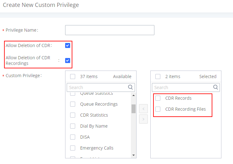
To assign custom privilege to a sub-admin, navigate to Web GUI🡪Maintenance🡪User Management🡪User Information🡪Create New User/Edit Users, select the custom privilege from “Privilege” option.
User Portal/Wave Privileges
The user can create customize privileges related to an extension’s User Portal and Wave. The created privilege can be affected to the extensions to limit or allow them to use certain functionalities related to Wave and the User Portal.
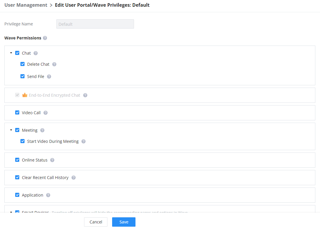
Wave Permissions
- Chat: Toggles ability to use the Wave Chat feature.
- Delete Chat: Toggles support for Wave to delete chats and chat history. This data will only be deleted on the Wave client side.
- Send File: Toggles file/image sending support in Wave chat. If disabled, users will still be able to download, view and forward chat files.
- End-to-End Encrypted Chat*: Toggles ability to use the Wave End-to-End Encrypted Chat feature.
- Video Call: Toggles ability to use the Wave Video Call feature.
- Meeting: Toggles ability to use the Wave Meeting feature.
- Start Video During Meeting: Toggles ability to use the Wave Start During Meeting feature.
- Online Status: Toggles ability to set Wave online status such as “Busy”, “Appear Away”, “Do Not Disturb”, “Appear Offline”, etc. If unchecked, the status will be displayed as only either “Online” or “Idle”.
- Clear Recent Call History: Toggles ability to delete recent call history entries and entire recent call history on Wave.
- Application: Toggles ability to access the “Applications” page under Wave Desktop and Wave Web.
- Smart Devices: Toggling off privileges will hide the corresponding pages and options in Wave.
- Door System
- Monitor
- Call Device (CTI)
- 3rd Party Applications
- App Store: Toggles ability to access the Wave App Store. If unchecked, the App Store will be hidden, but installed apps can still be used.
- Pre-installed Apps*: Configure Wave pre-installed add-ins and related settings.
User Portal/Wave Privileges
- Account Settings: If unchecked, the User Portal -> Basic Information -> Account Settings page and the Wave -> Sidebar -> User -> Account Settings option will be hidden.
- Extension Settings: If unchecked, the extension’s User Portal->Basic Information->Extensions page and the Wave->Sidebar->User->Call Settings option will be hidden.
- Do Not Disturb: Toggles ability to set DND through the User Portal.
- SIP/IAX Password & AuthID: Toggles ability to access the SIP/IAX Password and AuthID settings under the User Portal->Basic Information->Extensions->Basic Settings page.
- Configuration Voicemail
- Deleting Recordings: Toggles ability to delete recordings through the User Portal and Wave. For Wave, this includes the ability to delete call logs, meeting details,and recordings.
- Personal Data: Toggling off privileges will hide the corresponding pages and options in the User Portal and Wave.
- CDR
- Follow Me
- Voicemail
- Recordings files
- Fax Files
- SCA
- Other Features: Toggling off privileges will hide the corresponding pages and options in the User Portal and Wave.
- Fax Sending
- Call Queue
- Schedule Call
*: Features which are marked by an asterisk are a part of RemoteConnect plans.
User Endpoint Access Point
The User Endpoint Access History tab allows the administrator to view the access history of all extensions, the time on which the access has occurred, the IP addresses from which the extensions were accessed, and whether they were accessed from the User Portal, Wave Web/Desktop, or mobile. Extension access from the SIP endpoints won’t be logged in this page.
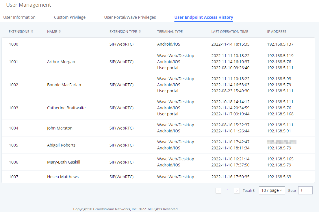
Operation Log
Super Admin has the authority to view operation logs on GCC601X(PBX Module) Web GUI🡪Maintenance🡪User Management🡪Operation Log page. Operation logs list operations done by all the Web GUI users, for example, Web GUI login, creating trunk, creating outbound rule etc. There are 7 columns to record the operation details “Date”, “Username”, “IP Address”, “Results”, “Page Operation”, “Specific Operation” and “Remark”.
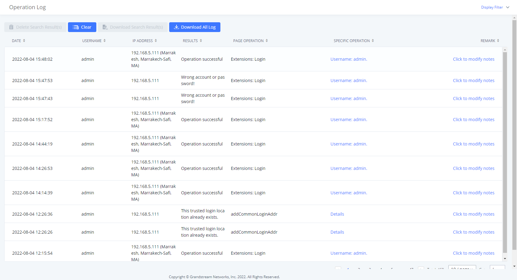
The operation log can be sorted and filtered for easy access. Click on ![]() or
or ![]() at the top of each column to sort. For example, clicking on
at the top of each column to sort. For example, clicking on ![]() for “Date” will sort the logs according to newer operation date and time. Clicking on
for “Date” will sort the logs according to newer operation date and time. Clicking on ![]() for “Date” will reverse the order.
for “Date” will reverse the order.
User could also filter the operation logs by time condition, IP address and/or username. Configure these conditions and then click on ”Display Filter”.
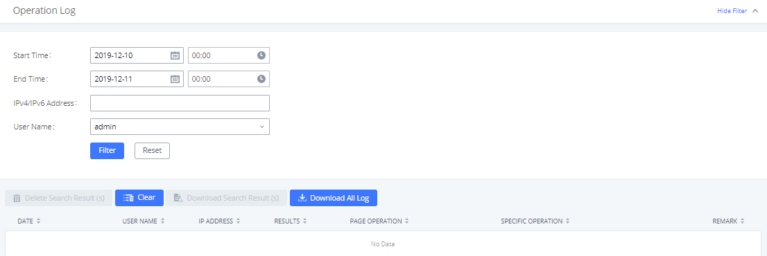
The above figure shows an example that operations made by user “support” on device with IP 192.168.40.173 from 2014-11-01 00:00 to 2014-11-06 15:38 are filtered out and displayed.
To delete operation logs, users can perform filtering first and then click on ![]() to delete the filtered result of operation logs. Or users can click on
to delete the filtered result of operation logs. Or users can click on ![]() to delete all operation logs at once.
to delete all operation logs at once.
Syslog
On the IPPBX, users could dump the syslog information to a remote server under Web GUI🡪Maintenance🡪Syslog. Enter the syslog server hostname or IP address and select the module/level for the syslog information as well as Process Log Level.
The default syslog level for all modules is “error”, which is recommended in your IPPBX settings because it can be helpful to locate the issues when errors happen.
Some typical modules for IPPBX functions are as follows and users can turn on “NOTICE” and “VERBOSE” levels besides “error” level.
- pbx: This module is related to general PBX functions.
- pjsip: This module is related to SIP calls.
System Events
The IPPBX can monitor important system events, log the alerts, and send Email notifications to the system administrator.
Alert Events List
The system alert events list can be found under Web GUI 🡪 Maintenance 🡪 System Events. The following event and their actions are currently supported on the IPPBX which will have alert and/or Email generated if occurred:
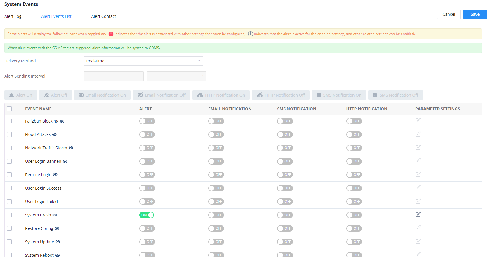
Alert Events |
Fail2ban Blocking |
Flood Attacks |
System Crash |
TLS Cert Expiration |
Cloud IM Abnormal |
Data Sync Backup |
Switching File Storage Path |
Emergency Calls |
SIP Outgoing Call through Trunk Failure |
SIP Internal Call Failure |
Remote Concurrent Calls |
Excessive Outbound Calls |
Outbound Call Duration |
Trunk Outbound Call Duration Usage |
Trunk Concurrent Calls |
Register SIP Trunk Failed |
SIP Peer Trunk Status |
Register SIP trunk failed |
SIP Lost Registration |
Click on
![]() to configure the parameters for each event. See examples below.
to configure the parameters for each event. See examples below.
- Fail2ban blocking: If the system Fail2ban is blocking, the event will be recorded in the alert log.
- User login banned: If user login is blocked, the event will be recorded in the alert log.
- Remote Login: An alert will be generated upon a remote login.
- System Update
- Restore Config: Once the system configuration is restored, the configuration restoration event will be recorded in the alert log.
- System Update: Once the system is upgraded, the system upgrade event will be recorded in the alarm log.
- System Reboot: IPPBX will detect the system restart and will send an alert for it. There are two kinds of reboots that the IPPBX detects, normal and abnormal reboots. Normal reboots are the reboots that are done when you press the restart button on the web UI, reboot that occur after updating the firmware, HA backup reboot etc… Abnormal reboots are the reboots that occur due to a system failure. Normal reboots are registered in the alert log and they are not pushed to GDMS, while abnormal reboots are registered in the alert list and are pushed to GDMS.
- HA failure warning: After the HA dual-system hot backup disaster recovery function is enabled in the IPPBX device, the HA fault alarm is automatically turned on. When the device has a software and hardware related fault, an HA fault alarm is generated.
- Cloud IM Abnormal: An alert message will be generated f the Cloud IM encounter any issue or exhibit any abnormal behavior.
- Modify Super Admin Password: Once the super administrator password is modified, the system will record the password modification event in the alarm log.
- Emergency Calls: If the system generates an emergency call, the event will be recorded in the alert log.
- Register SIP trunk failed
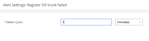
- Detect Cycle: The IPPBX will detect the failure of SIP trunk registration at a set interval. Users can enter the number and then select second(s)/minute(s)/hour(s)/day(s) to configure the cycle.
- SIP peer trunk status: If the SIP peer trunks status is abnormal, the event will be recorded in the alert log.
- SIP Outgoing Call through Trunk Failure: If the system SIP trunk outgoing call fails, the event will be recorded in the alert log.
- Register SIP failed
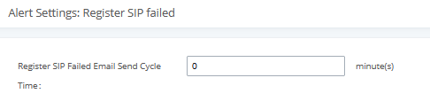
Configure the sending period of the SIP registration failure alert. The first registration failure alert of the same IP to the same SIP account will be sent immediately, and then no alerts will be sent for similar failure warnings in the cycle time. After the cycle time expires, an alert will be sent again to count the number of occurrences of similar SIP registration failure alerts during the cycle. When set to 0, alerts are always sent immediately.
- SIP lost registration: If System SIP extension registration is lost, the event will be recorded in the alert log. SIP Internal Call Failure: If the system SIP extension call fails within the office, the event will be recorded in the alert log.
- High Frequency Outgoing Call: When an extension initiates calls frequently, an alert will be logged in the alert log and a notification will be pushed to the GDMS and through email as well.
- Remote concurrent calls: If the remote concurrent call fails, the event will be recorded in the alert log.
- Trunk Outbound Call Duration Usage:
- Trunk Concurrent Calls: When the system detects that the number of concurrent calls of a certain relay exceeds the threshold set by the relay within a certain period of time, the event will be recorded in the alarm log. Calls are not restricted if the threshold is exceeded.
- User login success: Successful user login events will be recorded in the alert log.
- User login failed: User login failure events will be recorded in the alert log.
- Data Sync Backup: If the system performs data synchronization and backup abnormalities, the event will be recorded in the alert log.
Alert Log
Under Web GUI🡪Maintenance🡪System Events🡪Alert Log, system messages from triggered system events are listed as alert logs. The following screenshot shows system crash alert logs.
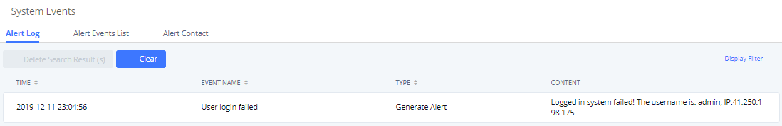
User could also filter alert logs by selecting a certain event category, type of alert log, and/or specifying a certain time period. The matching results will be displayed after clicking on
![]() . Alert logs are classified into two types by the system:
. Alert logs are classified into two types by the system:
- Generate Alert: Generated when alert events happen, for example, alert logs for disk usage exceeding the alert threshold.
- Restore to Normal: Generated when alert events being cleared, for example, logs for disk usage dropping back below the alert threshold.
User could filter out alert logs of “Generate Alert” or “Restore to Normal” by specifying the type according to need. The following figure shows an example of filtering out alert logs of type of “Restore to Normal”.
Alert Contact
This feature allows the administrator to be notified when one of the Alert events mentioned above happens. Users could add administrator’s Email address under Web GUI🡪Maintenance🡪System Events🡪Alert Contact to send the alert notification to an email (Up to 10 Email addresses can be added) or also specify an HTTP server where to send this alert.
Super Admin Email | Configure the email addresses to send alert notifications to. Up to 10 email addresses can be added. |
Admin Email | Configure the email addresses to send alert notifications to. Up to 10 email addresses can be added. |
Email Template | Please refer to section [Email Templates] |
Protocol | Protocol used to communicate with the server. HTTP or HTTPS. Default one is HTTP. |
HTTP Server | The IP address or FQDN of the HTTP/HTTPS server. |
HTTP Server Port | HTTP/HTTPS port |
Warning Template | Customize the template used for system warnings. By default: {“action”:”${ACTION}”,”mac”:”${MAC}”,”content”:”${WARNING_MSG}”} |
Notification Template | Customize the notification template to receive relevant alert information. By default: {“action”:”${ACTION}”,”cpu”:”${CPU_USED}”,”memery”:”${MEM_USED}”,”disk”:”${DISK_USED}”,”external_disk”:”${EXTERNAL_DISK_USED}”} Note: The notification message with “action:0” will be sent periodically if Notification Interval is set. |
Notification Interval | Modifies the frequency at which notifications are sent in seconds. No notifications will be sent if the value is “0”. Default value: 20 |
Template Variables | ${MAC} : MAC Address ${WARNING_MSG} : Warning message ${TIME} : Current System Time ${CPU_USED} : CPU Usage ${MEM_USED} : Memory Usage ${ACTION} : Message Type. Refer to [Alert Events] ${DISK_USED} : Disk Usage ${EXTERNAL_DISK_USED} : Disk Usage |
Backup
Backup/Restore
Users could backup the IPPBX configurations for restore purpose under Web GUI🡪Maintenance🡪Backup🡪Backup/Restore.
Click on ”Backup” to create a new backup file. Then the following dialog will show.
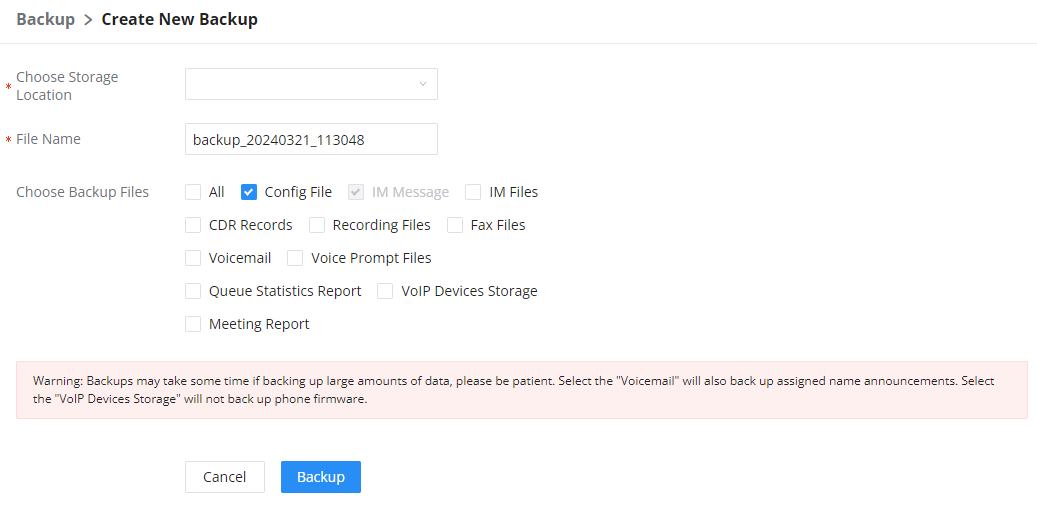
- Choose the location of where the backup will be stored.
- Choose the type(s) of files to be included in the backup.
- Name the backup file.
- Click on “Backup” to start backup.
Data Sync
Besides local backup, users could backup the voice records/voice mails/CDR in a daily basis to a remote server via SFTP protocol automatically under Web GUI🡪Maintenance🡪Backup🡪Data Sync.
The client account supports special characters such as @ or “.” Allowing the use email address as SFTP accounts. It allows users as well to specify the destination directory on SFTP server for backup file. If the directory does not exist on the destination, IPPBX will create the directory automatically.
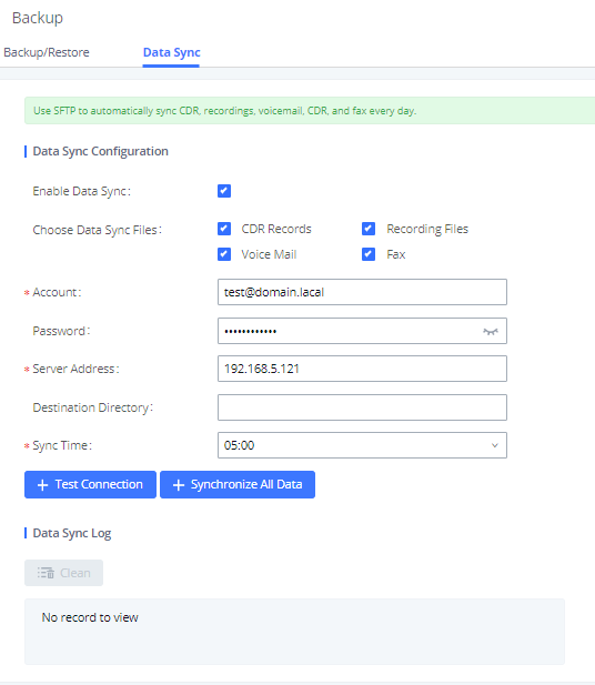
Enable Data Sync | Enable the auto data sync function. The default setting is “No”. |
Account | Enter the Account name on the SFTP backup server. |
Password | Enter the Password associate with the Account on the SFTP backup server. |
Server Address | Enter the SFTP server address. |
Specify the directory in SFTP server to keep the backup file. Format: ‘xxx/xxx/xxx’, If this directory does not exist, IPPBX will create this directory automatically. | |
Sync Time | Enter 0-23 to specify the backup hour of the day. |
Before saving the configuration, users could click on ![]() . The IPPBX will then try connecting the server to make sure the server is up and accessible for the IPPBX. Save the changes and all the backup logs will be listed on the web page. After data sync is configured, users could also manually synchronize all data by clicking on
. The IPPBX will then try connecting the server to make sure the server is up and accessible for the IPPBX. Save the changes and all the backup logs will be listed on the web page. After data sync is configured, users could also manually synchronize all data by clicking on ![]() instead of waiting for the backup time interval to come.
instead of waiting for the backup time interval to come.
System Cleanup
Reboot
Users could perform reset and reboot under Web GUI>Maintenance>System Cleanup>Reboot.
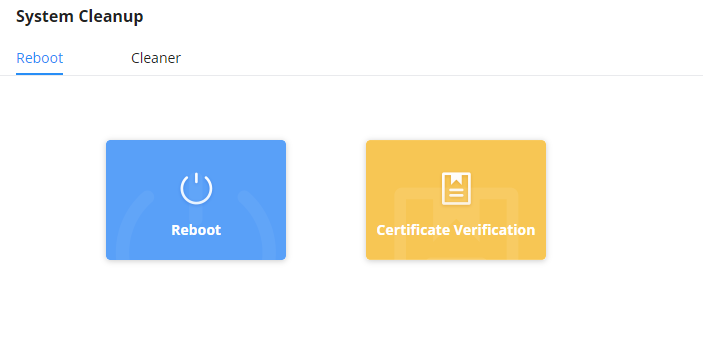
Reboot
When the user clicks on reboot, a confirmation prompt will appear. To proceed with rebooting the device, please click “OK”.
Certificate Verification
This option is used to verify the validity of the TLS certificate used to connect to the PBX module over HTTPS.
Cleaner
Users could configure to clean the Call Detail Report/Voice Records/Voice Mails etc… manually and automatically under Web GUI🡪Maintenance🡪System Cleanup/Reset🡪Cleaner.
The following screenshot show the settings and parameters to configure the manual cleaner feature on IPPBX.
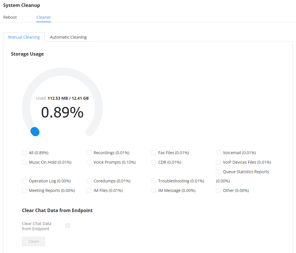
IPPBX regularly cleans up CDRs, report data, chat data, recording files, historical appointment meeting records, voice mail, backup files, and fax files. The report data includes queue statistics report and conference room call statistics report; chat data includes chat messages and chat shared files; historical appointment conferences include audio and video conference appointment records. Automatic cleanup is not enabled by default and supports regular cleanup of database data based on dimensions such as cleanup time, cleanup conditions, and cleanup interval.
User can also set an automatic cleaning under Cleaner🡪Automatic Cleaning. The following screenshot show the settings and parameters to configure the cleaner feature on IPPBX.
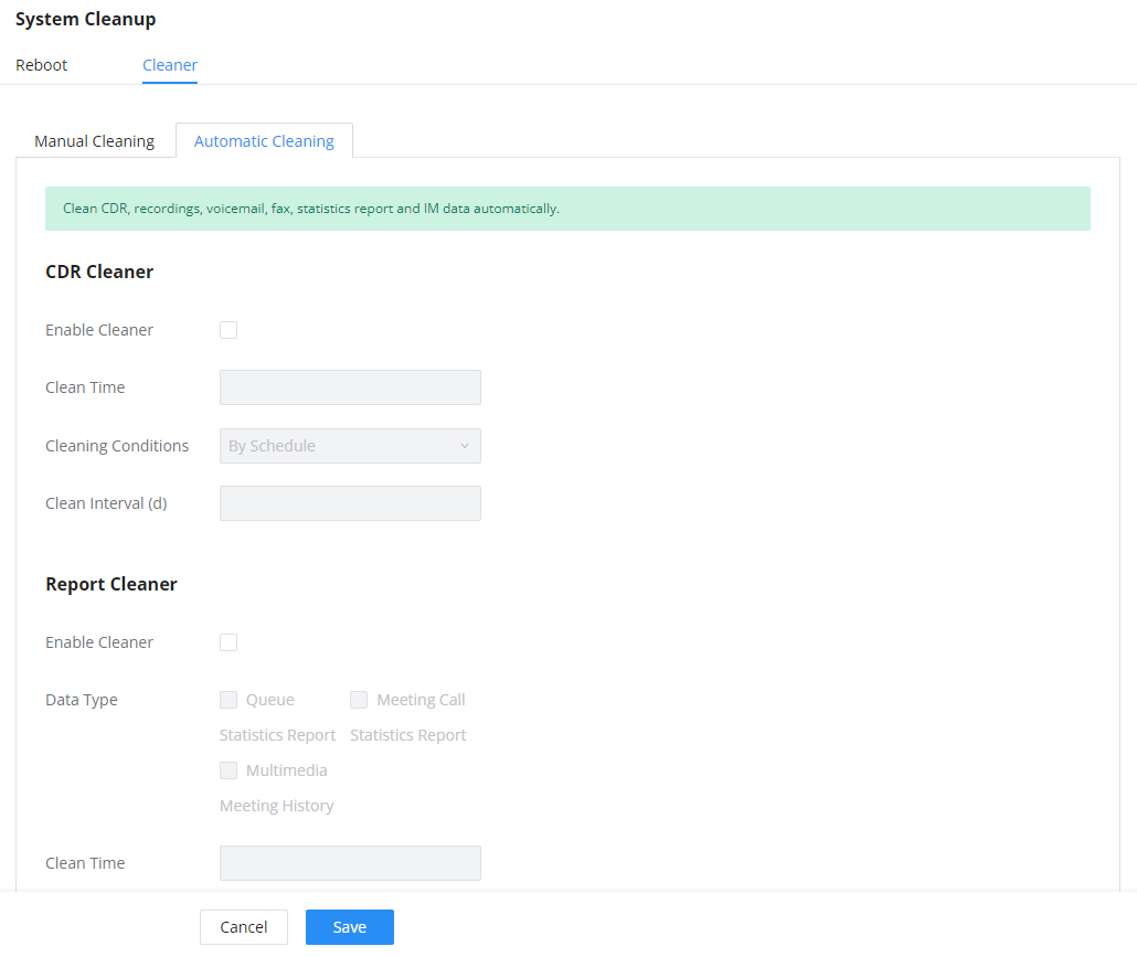
Enable CDR Cleaner | |
CDR Clean Time | Enter 0-23 to specify the hour of the day to clean up CDR. |
Cleaning Conditions | By Schedule: If the clean interval is 3, cleaning will be performed every 3 days to remove all records that were generated 3 days ago. Keep Last X Records: If the max number of CDR has been reached, CDR will be deleted starting with the oldest entry at the configured cleaning time.(Note: The amount of records displayed on the page of call queue statistics is not one-to-one with the actual amount of records in the database.) Keep Last X Days: Delete all entries older than X days. |
Clean Interval | Enter 1-30 to specify the day of the month to clean up CDR when By Schedule is selected as Cleaning Conditions. |
Max Entries | Set the maximum number of CDR entries to keep when Keep Last X Records is selected as Cleaning Conditions. |
Keep Last X Day | Enter the number of days of call log entries to keep when Keep Last X days is selected as Cleaning Conditions. |
Enable Report Cleaner | Enable scheduled queue log cleaning. By default, is disabled. |
| |
Enter the hour of the day to start the cleaning. The valid range is 0-23. | |
Cleaning Conditions | By Schedule: If the clean interval is 3, cleaning will be performed every 3 days to remove all records that were generated 3 days ago. Keep Last X Records: If the max number of Queue Statistics has been reached, Queue Statistics will be deleted starting with the oldest entry at the configured cleaning time.(Note: The amount of records displayed on the page of call queue statistics is not one-to-one with the actual amount of records in the database.) Keep Last X Days: Delete all entries older than X days. |
Enter how often (in days) to clean queue logs when By Schedule is selected as Cleaning Conditions. The valid range is 1-30. | |
Max Entries | Set the maximum number of Queue Statistics entries to keep when Keep Last X Records is selected as Cleaning Conditions. |
Keep Last X Day | Enter the number of days of call log entries to keep when Keep Last X days is selected as Cleaning Conditions. |
Enable Conference Statistics Report Cleaner | Enable scheduled Conference log cleaning. By default, is disabled. |
Cleaning Conditions |
|
Clean Interval | Enter how often (in days) to clean queue logs when By Schedule is selected as Cleaning Conditions. The valid range is 1-30. |
Max Entries | Set the maximum number of Conference Statistics Report entries to keep when Keep Last X Records is selected as Cleaning Conditions. |
Keep Last X Day | Enter the number of days of call log entries to keep when Keep Last X days is selected as Cleaning Conditions. |
Enable File Cleaner | Enter the Voice Records Cleaner function. |
Clean Files in External Device | If enabled the files in external device (USB/SD card) will be atomically cleaned up as configured. |
Choose Cleaner File | Select the files for system automatic clean.
|
Clean time | Enter the hour of the day to start the cleaning. The valid range is 0-23. |
Cleaning Conditions |
|
File Clean Interval | Enter 1-30 to specify the day of the month to clean up the files. |
File Clean Threshold | Enter the internal storage disk usage threshold (in percent). Once this threshold is exceeded, the file cleanup will proceed as scheduled. Valid range is 0-99. |
Keep Last X Days | Automatically delete all recordings older than this x days when the threshold is reached. If not set, all data is cleared |
Cleaner Log | Press Clean “button” to clean the cleaner’s log. |
All the cleaner logs will be listed on the bottom of the page.
Network Troubleshooting
Ethernet Capture
Ethernet Capture allows capturing the traffic of the IPPBX for troubleshooting purposes. To access Ethernet Capture feature, please navigate to Maintenance → Network Troubleshooting → Ethernet Capture
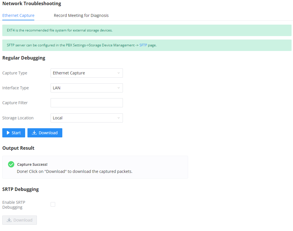
The capture packets can be stored locally and downloaded for analysis. However, if the user is diagnosing a randomly-occurring issue, he/she can run a continuous packet capture which can be limited by the size of the packet capture and the number of packet capture instances
Capture Type | Ethernet Capture: Gets a packet capture of all network traffic going through the device. WebSocket Capture: Gets a packet capture of WebSocket protocol. Mainly used for troubleshooting Wave Web calling and conferencing issues. |
Interface Type | Select the network interface to monitor. |
Capture Filter | Enter the filter to obtain the specific types of traffic, such as (host, src, dst, net, proto…). |
Storage Location |
|
Save to External Storage | When or more external storage units are connected to the UCM6300 series, the user will be able to pick which one to use. |
Destination Directory | When SFTP is selected, this option will appear. Please enter the directory path in which you would like to store the captured packets. |
Packet Capture Size | This option appears only when "External Storage" or "SFTP" options are selected. |
Number of Packet Capture | Define the maximum number of the packets captured. The available options are 5, 10, and 20 packets. |
Start capturing network traffic. | |
Stop capturing network traffic. | |
Download the captured packets. This option can only be used when the captured packets are stored locally. | |
Enable SRTP Debugging | Check this box to troubleshoot calls encrypted with TLS/SRTP. |
The output result is in .pcap format. Therefore, users could specify the capture filter as used in general network traffic capture tool (host, src, dst, net, protocol, port, port range) before starting to capture the trace.
Record Meeting For Diagnosis
Recording the meeting on the IPPBX allows the user to take a recording sample of a meeting to diagnose the issues that might be encountered. This allows the user to pinpoint the connections which are encountering issues when using the meeting feature.
Service Check
Enable Service Check to periodically check IPPBX service status. Check Cycle is configurable in seconds and the default setting is 60 sec. Check Times is the maximum number of failed checks before restart the IPPBX. The default setting is 3. If there is no response from IPPBX after 3 attempts (default) to check, current status will be stored and the internal service in IPPBX will be restarted.
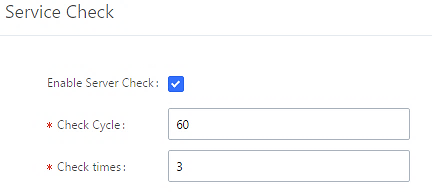
CDR
CDR
CDR (Call Detail Record) is a data record generated by the PBX that contains attributes specific to a single instance of phone call handled by the PBX. It has several data fields to provide detailed description for the call, such as phone number of the calling party, phone number of the receiving party, start time, call duration, etc.
On the IPPBX, the CDR can be accessed under Web GUI🡪CDR🡪CDR. Users could filter the call report by specifying the date range and criteria, depending on how the users would like to include the logs to the report. Click on “Filter” button to display the generated report.
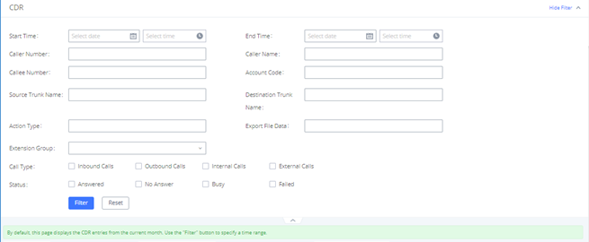
Call Type | Groups the following:
|
Status | Filter with the call status, the available statuses are the following:
|
Source Trunk Name | Select source trunk(s) and the CDR of calls going through inbound the trunk(s) will be filtered out. |
Destination Trunk Name | Select destination trunk(s) and the CDR of calls going outbound through the trunk(s) will be filtered out. |
Filter calls using the Action Type, the following actions are available:
| |
Extension Group | Specify the Extension Group name to filter with. |
Select the fields that will be exported, the following fields are available:
| |
Account Code | Select the account Code to filter with. If pin group CDR is enabled, the call with pin group information will be displayed as part of the CDR under Account Code Field. |
Start Time | Specify the start time to filter the CDR report. Click on the calendar icon on the right and the calendar will show for users to select the exact date and time. |
End Time | Specify the end time to filter the CDR report. Click on the calendar icon on the right and the calendar will show for users to select the exact date and time. |
Caller Number | Enter the caller number to filter the CDR report. CDR with the matching caller number will be filtered out. User could specify a particular caller number or enter a pattern. ‘.’ matches zero or more characters, only appears in the end. ‘X’ matches any digit from 0 to 9, case-insensitive, repeatable, only appears in the end. For example: 3XXX: It will filter out CDR that having caller number with leading digit 3 and of 4 digits’ length. 3.: It will filter out CDR that having caller number with leading digit 3 and of any length. |
Caller Name | Enter the caller name to filter the CDR report. CDR with the matching caller name will be filtered out. |
Enter the callee number to filter the CDR report. CDR with the matching callee number will be filtered out. Note: The “Callee Number” filter field supports specifying Pattern (example: 3XXX) or using Leading digits (example: 3.) as filtering options. |
The call report will display as the following figure shows.
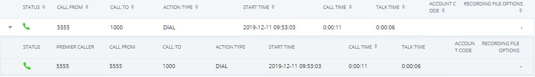
The CDR report has the following data fields:
- Start Time
Format: 2019-12-11 09:53:03
- Action Type
Example:
IVR
DIAL
WAKEUP
- Call From
Example format: 5555
- Call To
Example format: 1000
- Call Time
Format: 0:00:11
- Talk Time
Format: 0:00:06
- Account Code
Example format:
Grandstream/Test
- Status
Answered, Busy, No answer or Failed.
Users could perform the following operations on the call report.
- Sort by “Start Time”
Click on the header of the column to sort the report by “Start Time”. Clicking on “Start Time” again will reverse the order.
- Download Searched Results
Click on “Download Search Result(s)” to export the records filtered out to a .csv file.
- Download All Records
Click on “Download All Records” to export all the records to a .csv file.
- Delete All
Click on ![]() button to remove all the call report information.
button to remove all the call report information.
- Delete Search Result
On the bottom of the page, click on ![]() button to remove CDR records that appear on search results.
button to remove CDR records that appear on search results.
- Play/Download/Delete Recording File (per entry)
If the entry has audio recording file for the call, the three icons on the rightest column will be activated for users to select. In the following picture, the second entry has audio recording file for the call.
Click on ![]() to play the recording file; click on
to play the recording file; click on ![]() to download the recording file in .wav format; click on
to download the recording file in .wav format; click on ![]() to delete the recording file (the call record entry will not be deleted).
to delete the recording file (the call record entry will not be deleted).
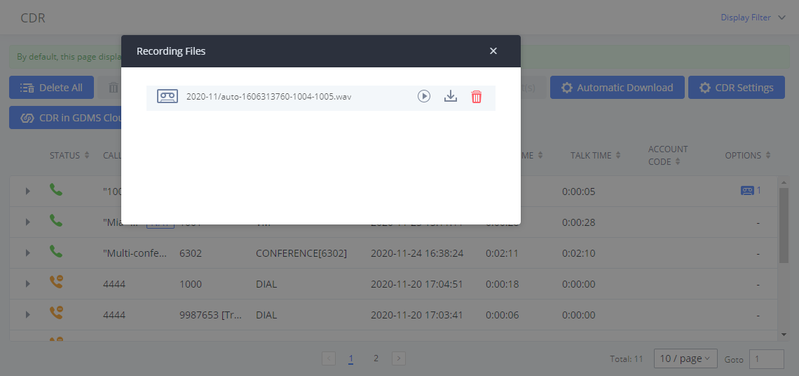
- Automatic Download CDR Records
User could configure the IPPBX to automatically download the CDR records and send the records to multiple Email recipients in a specific hour. Click on “Automatic Download Settings” and configure the parameters in the dialog below.
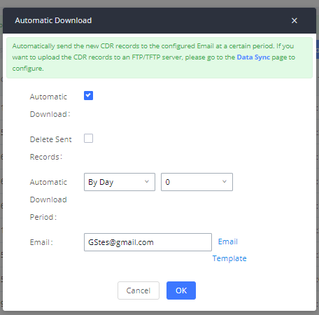
To receive CDR record automatically from Email, check “Enable” and select a time period “By Day” “By Week” or “By Month”, select Hour of the day as well for the automatic download period. Make sure you have entered an Email or multiple email addresses where to receive the CDR records.
The user can click on the option icon for a specific call log entry to view details about this entry, such as premier caller and transferred call information.

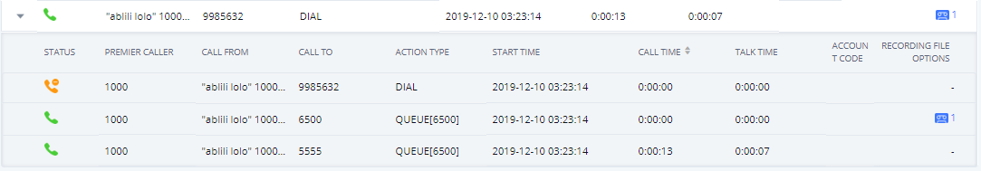
Downloaded CDR File
The downloaded CDR (.csv file) has different format from the Web GUI CDR. Here are some descriptions.
- Caller number, Callee number
“Caller number”: the caller ID.
“Callee number”: the callee ID.
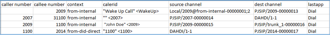
- Context
There are different context values that might show up in the downloaded CDR file. The actual value can vary case by case. Here are some sample values and their descriptions.
from-internal: internal extension makes outbound calls.
ext-did-XXXXX: inbound calls. It starts with “ext-did”, and “XXXXX” content varies case by case, which also relate to the order when the trunk is created.
ext-local: internal calls between local extensions.
- Source Channel, Dest Channel
Example:

“SIP” means it is a SIP call. There are three format:
(a) PJSIP/NUM-XXXXXX, where NUM is the local SIP extension number. The last XXXXX is a random string and can be ignored.
(c) PJSIP/trunk_X/NUM, where trunk_X is the internal trunk name, and NUM is the number to dial out through the trunk.
(c) PJSIP/trunk_X-XXXXXX, where trunk_X is the internal trunk name and it is an inbound call from this trunk. The last XXXXX is a random string and can be ignored.
There are some other values, but these values are the application name which are used by the dialplan.
Local/@from-internal-XXXXX: it is used internally to do some special feature procedure. We can simply ignore it.
Hangup: the call is hung up from the dialplan. This indicates there are some errors or it has run into abnormal cases.
Playback: play some prompts to you, such as 183 response or run into an IVR.
ReadExten: collect numbers from user. It may occur when you input PIN codes or run into DISA
CDR Export Customization
Users can select the data they want to see in exported CDR reports by first clicking on the Filter button on the CDR page under CDR🡪CDR and selecting the desired information in the Export File Data field.
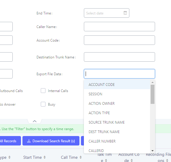
CDR in GDMS Cloud
Cloud Storage for CDR Record which can be displayed under CDR 🡪 CDR in GDMS Cloud.
Statistics
The IPPBX supports the function of concurrent call statistics. This function provides users with statistics on the number of concurrent calls of all VOIP trunks (SIP trunks ). Users can set search criteria to generate custom charts. Select the trunk and time to view the chart of the maximum number of concurrent calls corresponding to the trunk in a certain day or month.
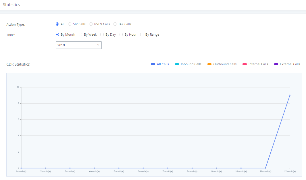
Trunk Type | Select one of the following trunk type.
|
Call Type | Select one or more in the following checkboxes.
|
Time Range |
|
Recordings
This page lists all the recording files recorded by “Auto Record” per extension/ring group/call queue/trunk, or via feature code “Audio Mix Record”. If external storage device is plugged in, for example, SD card or USB drive, the files are stored on the external storage. Otherwise, internal storage of the IPPBX will be used.
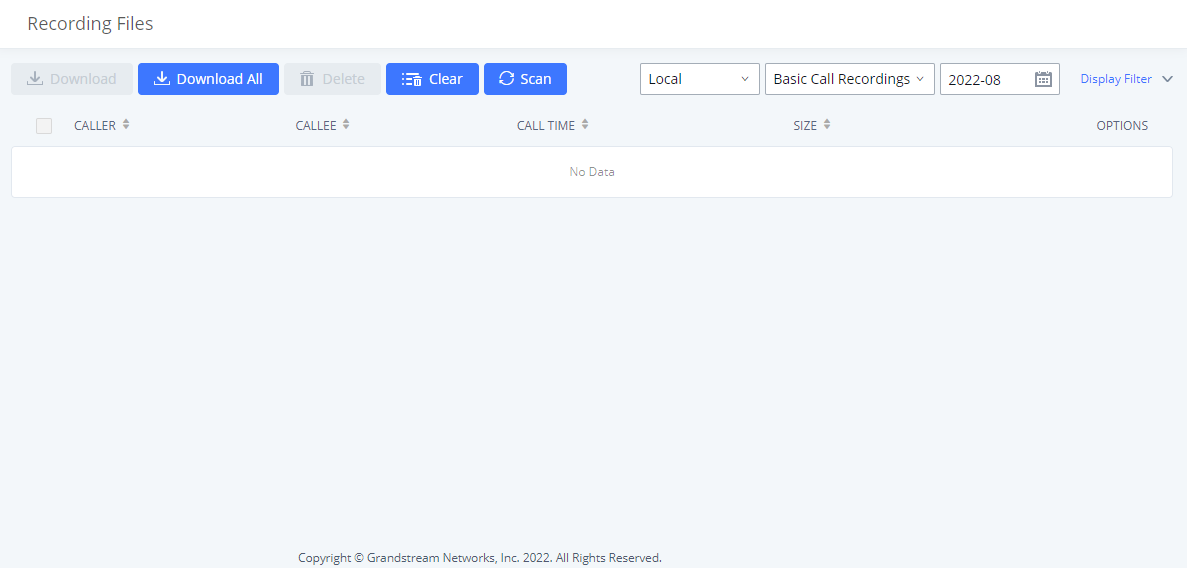
- Click on “Download” to batch-download the selected recording files.
- Click on “Download All” to download all the recording files.
- Click on “Delete” to batch-delete the selected recording files.
- Click on “Clear” to delete all the recording files.
- Click on “Scan” to retrieve the file information and display all the recording files on external storage. The IPPBX automatically retrieves the info of the first 5000 files from external storage already. This button can be used when the number of files stored on the external storage exceeds 5000 files and it requires manual file scanning.
- Select either “USB Disk” or “Local” to show recording files stored on external or internal storage, depending on selected storage space.
- Select whether to show call recordings, queue recordings or conference recordings.
- Click on to download the recording file in .wav format.
- Click on to delete the recording file.
- To sort the recording file, click on the title “Caller”, “Callee” or “Call Time” for the corresponding column. Click on the title again can switch the sorting mode between ascending order or descending order.
REMOTECONNECT
An integrated & important part of Grandstream’s GDMS cloud-based device management service which runs on Amazon Web Services (AWS) with 99.999% reliability. RemoteConnect cloud service supports hassle-free Work-From-Home audio/video communications & collaborations using WebRTC-based license-free “Grandstream Wave” softphones for desktop/Web/mobile devices (plus GUV series of USB headsets/Webcams), zero-touch out-of-box automated NAT firewall traversal for remote users & devices, IT-friendly remote management of the IPPBX and attached endpoint devices, and more.
The RemoteConnect can be configured under RemoteConnect tab on the web UI of the IPPBX.
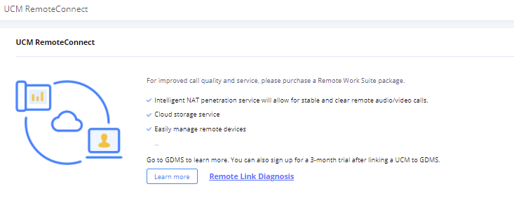
On the GDMS platform, sign in and go to Device🡪PBX Device page, click on “Add Device” to add your IPPBX device to the GDMS system, once done an open beta plan will be assigned to the IPPBX.
In daily operation, the user can click the “Diagnosis” button to diagnose the remote service system. The specific diagnosis content includes media service (STUN/TURN), GDMS link and heartbeat detection, tunnel service (SIP/Web Socket), Cloud IM, IPPBX bandwidth speed measurement.
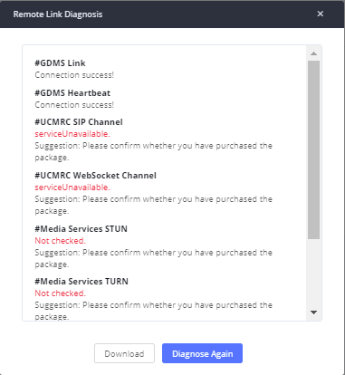
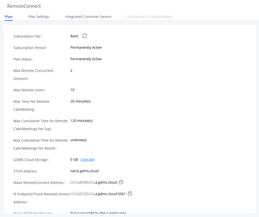
Plan Settings
After IPPBX is added into GDMS, all SIP extensions on the IPPBX will be synced up to GDMS automatically for users to allocate and manage SIP extension for their end devices. Also, the media NAT Traversal service, alert event sync configuration items are checked by default, the CDR data cloud storage in GDMS should be manually checked according to user needs.
The IPPBX supports to allow authorized GDMS user to access IPPBX without entering the password once the super admin or admin checks “Enable Passwordless Remote Access”. If super admin enables this option, then the IPPBX will be accessed using the super admin account. If admin enables this option, then the IPPBX will be accessed using the admin account. Super admin and admin can see whether this option is enabled. Additionally, super admin can disable all accounts who enabled this option while admin can only disable access for the account itself.
The settings are under IPPBX web GUI: RemoteConnect🡪Plan Settings.
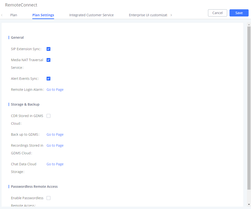
After adding IPPBX to the GDMS platform, IPPBX will synchronize all SIP extensions to the GDMS platform, this allows to use the GDMS platform for account allocation and terminal management.
The accounts synchronized to GDMS platform can be viewed on the GDMS-> VoIP Account->SIP Account page. As shown in the figure below:
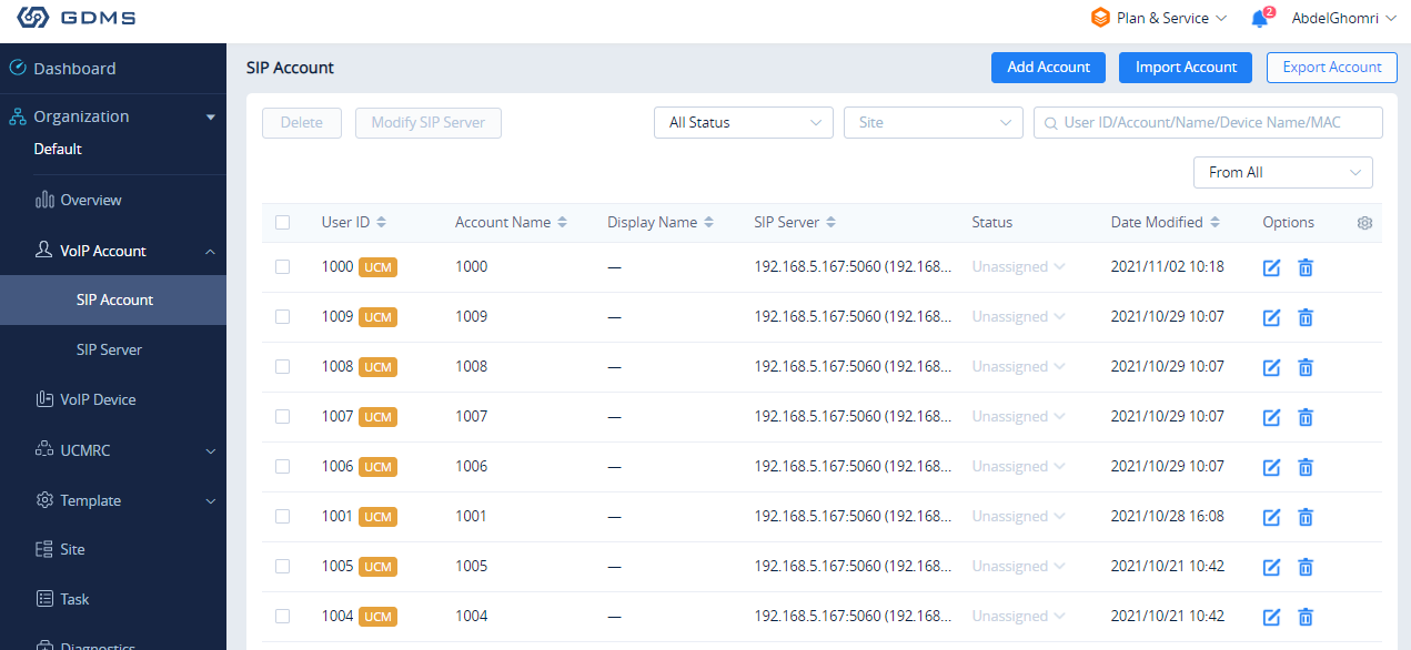
The Media NAT Traversal provides a fully automatic intelligent external network penetration service to ensure that you can make normal calls/conferences on the external network.
CDR data cloud storage provides a service of dumping to GDMS to prevent CDR from continuously increasing occupying IPPBX storage space.
Alarm event synchronization is to synchronize the alarm information generated on IPPBX to the GDMS server.
Allow the administrator/super administrator to open it. After clicking on open with an account, the subsequent password-free login will use the account. All administrators and super administrators can see whether this IPPBX is enabled.
Super administrators can check and uncheck all the exemption lists; administrators can check and uncheck the exemption status of this account, and the corresponding account exemption access function will be closed after cancellation.
Integrated Customer Service
To configure the Integrated Customer Service, go to the Web GUI 🡪 RemoteConnect 🡪 Integrated Customer Service page that allows users to download the SDK provided by the customer service system and integrate it on the website, so that the website can contact customer service for call operations. The call queue is used as the customer service number.
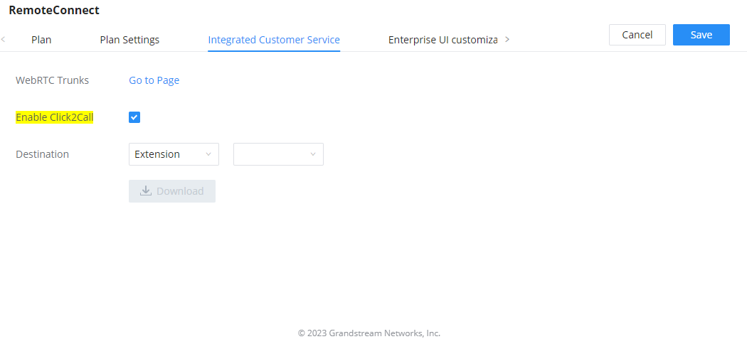
Enabling Click2Call will allow users to initiate a direct call from the web browser by clicking on the call button embedded on the website graphical interface. The calls initiated can be directed to call queues or a specific extension.
Enterprise UI Customization
With a RemoteConnect plan, on the Web GUI 🡪 RemoteConnect 🡪 Enterprise UI Customization page, users can edit the company name and select a local image file as the new logo. The company name acts on the text part with the logo, and the pictures are in different formats and sizes according to the logo position, which are 64*64px (only ico format is supported), 256*256px, 80*80px, which supports users in the “IPPBX management platform/login” “”, “Reset Password”, “Email Template”, “Wave_PC”, “Wave Login”, “Browser Label”, “Guide Page” interface preview.
- LOGO 1: Replaces Browser tab icon
- LOGO 2: Replaces the Grandstream banner on the top left corner of the management login page and emails.
- LOGO 3: Replaces the Grandstream logo on the top left corner of the Wave Web interface and IPPBX management interface.
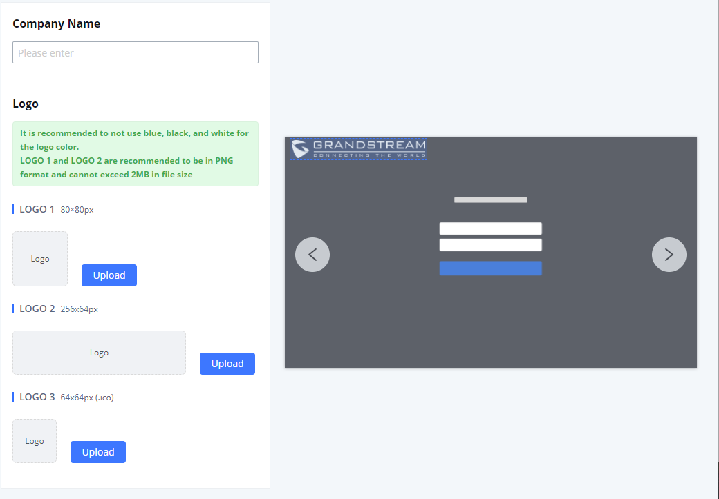
Statistics
After using RemoteConnect, all remote calls will be logged and concurrent remote calls will be displayed on the IPPBX. The concurrent remote calls can be viewed under IPPBX web GUI🡪RemoteConnect🡪Statistics page.
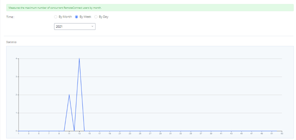
For more information, please visit http://ucmrc.gdms.cloud/intro.html
GDMS Cloud Storage Space
When the correspondent RemoteConnect plan is active, the user can access to a GDMS Cloud Storage Space to get an overview about how the storage space is being used. The data is represented in four categories of file types: CDR Data, Backup Data, Recording Files, and IM Files.
The user is also able to see the names of all the files stored in the GDMS Cloud Storage Space.
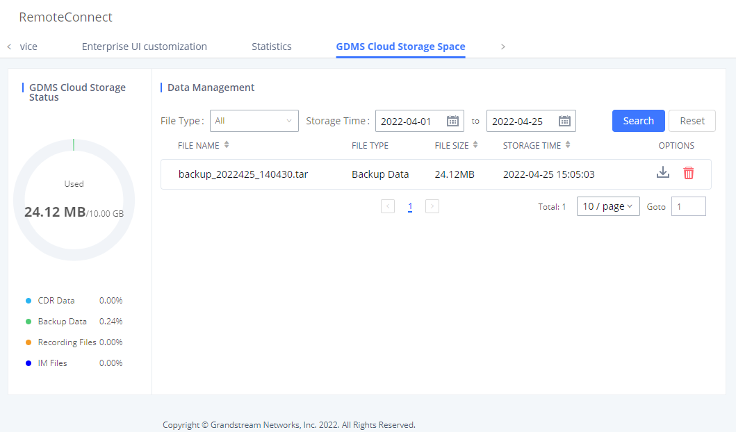
INTEGRATIONS
API Configuration
PBX API allows creating an interface between the IPPBX and an application to send HTTPS requests to the database of the IPPBX.
API Settings
Before accessing the API, the administrators need to enable API and configure the access/authentication information on the PBX first under Integrations 🡪 API Configuration. The API configuration parameters are listed in the tables below.
Field | Description |
PMS Module | Users can select the desired PMS module from the drop-down list.
|
Wakeup Prompt | A customized prompts that can be played when the wakeup call is answered. To customize it please navigate to PBX Settings 🡪 Voice Prompt 🡪 Custom Prompt |
Username | This username is used to authenticate into the PMS API. |
Password | This password is used to autheticate into the PMS API. |
Back Up Voicemail Recordings | Back up voicemail recordings to external storage after check-out. |
Automatically Clear Wakeup Calls | Scheduled wakeup calls for rooms can be cleared upong checking in or checking out.
|
Automatically Clear Wave Chat History | If enabled, room Wave chat history will be automatically cleared upon check-in or check-out. |
Automatically Reset User/Wave Password | If enabled, the User/Wave password of the room extension will be automatically reset to a random password upon check-out. |
For more details on CDR API (Access to Call Detail Records), REC API (Access to Call Recording Files) and PMS API, please refer the document in the link here:
- https://documentation.grandstream.com/knowledge-base/cdr-rec-api/
- https://documentation.grandstream.com/knowledge-base/cdr-rec-api/
- PMS API
API Queries Supported
The new API supports now new queries listed below which will accomplish certain requests and get data about different modules on PBX.
| Queries Supported |
| getSystemStatus |
| getSystemGeneralStatus |
| listAccount |
| getSIPAccount |
| updateSIPAccount |
| listVoIPTrunk |
| addSIPTrunk |
| getSIPTrunk |
| updateSIPTrunk |
| deleteSIPTrunk |
| listOutboundRoute |
| addOutboundRoute |
| getOutboundRoute |
| updateOutboundRoute |
| deleteOutboundRoute |
| listInboundRoute |
| addInboundRoute |
| getInboundRoute |
| updateInboundRoute |
| deleteInboundRoute |
| playPromptByOrg |
| listBridgedChannels |
| listUnBridgedChannels |
| Hangup |
| callbarge |
| listQueue |
| getQueue |
| updateQueue |
| addQueue |
| deleteQueue |
| loginLogoffQueueAgent |
| pauseUnpauseQueueAgent |
| listPaginggroup |
| addPaginggroup |
| getPaginggroup |
| updatePaginggroup |
| deletePaginggroup |
| listIVR |
| addIVR |
| getIVR |
| updateIVR |
| deleteIVR |
| cdrapi |
| recapi |
| pmsapi |
| queueapiget |
| getPinSets |
| addPinSets |
| updatePinSets |
| deletePinSets |
| cleanTerminalChatInformation |
| getSIPAccountQR |
| getCallQueuesMemberMessage |
| getQueueCalling |
CDR Real-time Output Settings | |
Enable | Enables real-time CDR output module. This module connects to selected IP addresses and ports and posts CDR strings as soon as it is available. |
Server Address | CDR server IP address |
Port | CDR server IP port |
Upload Prompts User Configuration | |
Username | Username used to upload prompts. |
Password | Password used to upload prompts. |
Upload Voice Prompt via API
Customers now can use the “Upload Prompts User Configuration” to upload/replace voice prompt files as an alternative method to the manual upload method on IPPBX PBX Settings🡪 Voice Prompt🡪 Custom Prompt.
The workflow of the prompt file upload goes as:
An HTTP/HTTPS request is sent to the IPPBX to upload/replace a voice prompt file, the request should include authentication details to the IPPBX and the name of the file to be uploaded. Then the IPPBX will contact an FTP server that should be hosted on the same IP address of the HTTP/HTTPS requester and download the prompt file from the FTP server.
The steps and conditions to upload the voice prompt via API are listed below:
- Configure the prompt User under Other Features 🡪 API Configuration 🡪 Upload Prompts User Configuration. By default, the username and password for voice prompt user are “Username: uploader; Password: uploader123”.
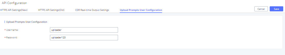
- Hash the password of the user configured to an MD5 Encryption format.
- Set the permission on the FTP server to Anonymous on the local computer hosting the FTP server and make sure that the default FTP port 21 is used.
- Send an HTTP/HTTPS command to trigger the Prompt file upload on the IPPBX. If IPPBX’s HTTP server is set to HTTPS, the example of the request sent to the IPPBX is:
https://192.168.124.89:8089/cgi?action=uploadprompt&username=uploader&password=9191a6394c21b3aabd779213c7179462&filename=test.mp3
If IPPBX’s HTTP server is set to HTTP, the example of the request sent to the IPPBX is:
https://192.168.124.89:8089/cgi?action=uploadprompt&username=uploader&password=9191a6394c21b3aabd779213c7179462&filename=test.mp3
For more details on CDR API (Access to Call Detail Records) and REC API (Access to Call Recording Files), please refer the document in the link here:
https://documentation.grandstream.com/knowledge-base/cdr-rec-api/AMI
The IPPBX supports Asterisk Manager Interface (AMI) with restricted access. AMI allows a client program to connect to an Asterisk instance commands or read events over a TCP/IP stream. It is particularly useful when the system admin tries to track the state of a telephony client inside Asterisk.
User could configure AMI parameters on IPPBX Web GUI🡪Integrations🡪AMI. For details on how to use AMI on IPPBX, please refer to the following AMI guide:
https://documentation.grandstream.com/knowledge-base/ami-asterisk-management-interface/CTI Server
IPPBX does support CTI server capabilities which are designed to be a part of the CTI solution suite provided by Grandstream, including GXP21XX and GXP17XX enterprise IP phones along with GS Affinity app.
Mainly the IPPBX will by default listening on port TCP 8888 for the connections from GS affinity application in order to interact, modify and serve data requests by the application which includes setting call features for the connected extension as call forward and DND.
Users can change the listening port under the menu page, Web GUI🡪Integrations🡪CTI Server as shown on below screenshot:
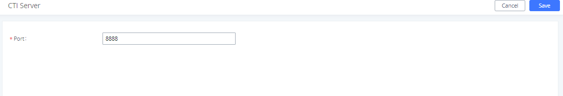
More information about GS affinity and CTI Support on Grandstream products series please refer to the following link:
https://documentation.grandstream.com/knowledge-base/gs-affinity-user-guide/CRM
Customer relationship management (CRM) is a term that refers to practices, strategies and technologies that companies use to manage and analyze customer interactions and data throughout the customer lifecycle, with the goal of improving business relationships with customers.
The PBX support the following CRMs: SugarCRM, VtigerCRM, Salesforce CRM and ACT! CRM, which allows users to look for contact information in the Contacts, Leads and / or Accounts tables, shows the contact record in CRM page, and saves the call information in the contact’s history.
Sugar CRM
Configuration page of the SugarCRM can be accessed via admin login, on the IPPBX WebGUI🡪Other Features🡪CRM.
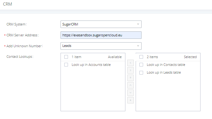
- Select “SugarCRM” from the CRM System Dropdown in order to use SugarCRM.
CRM System | Select a CRM system from the dropdown menu. |
CRM Server Address | Enter the IP address of the CRM server. |
Add Unknown Number | Add the new number to this module if it cannot be found in the selected module. |
Contact Lookups | Select from the “Available” list of lookups and press |
Once settings on admin access are configured:
- Click on
 and
and  .
. - Logout from admin access.
- Login to the IPPBX as user and navigate under “User Portal🡪Other Feature🡪CRM User Settings”.
Click on “Enable CRM” and enter the username/password associated with the CRM account then click on
![]() and
and
![]() . The status will change from “Logged Out” to “Logged In”. User can start then using SugarCRM features.
. The status will change from “Logged Out” to “Logged In”. User can start then using SugarCRM features.
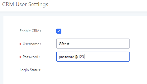
Vtiger CRM
Configuration page of the VtigerCRM can be accessed via admin login, on the IPPBX WebGUI🡪Other Features🡪CRM.
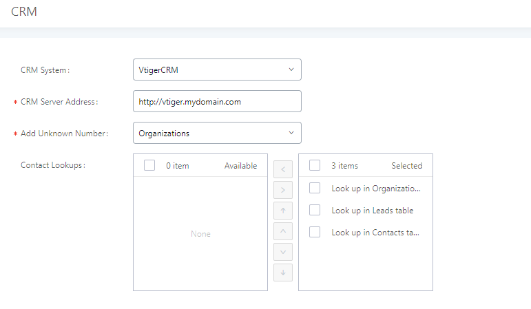
- Select “Vtiger CRM” from the CRM System Dropdown in order to use Vtiger CRM.
CRM System | Select a CRM system from the dropdown menu. |
CRM Server Address | Enter the IP address of the CRM server. |
Add Unknown Number | Add the new number to this module if it cannot be found in the selected module. |
Contact Lookups | Select from the “Available” list of lookups and press |
Once settings on admin access are configured:
- Click on and .
- Logout from admin access.
- Login to the IPPBX as user and navigate under “User Portal🡪Other Features🡪CRM User Settings”.
Click on “Enable CRM” and enter the username/password associated with the CRM account then click on ![]() and
and ![]() . The status will change from “Logged Out” to “Logged In”. User can start then using SugarCRM features.
. The status will change from “Logged Out” to “Logged In”. User can start then using SugarCRM features.

Salesforce CRM
Configuration page of the Salesforce CRM can be accessed via admin login, on the IPPBX Web GUI🡪Other Features🡪CRM”.
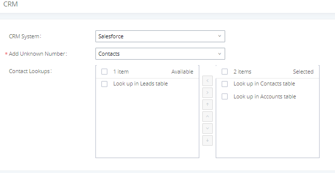
- Select “Salesforce” from the CRM System Dropdown in order to use Salesforce CRM.
CRM System | Select a CRM system from the dropdown menu, four CRM systems are available: SugarCRM, VtigerCRM, Salesforce and ACT! CRM. |
Add Unknown Number | Add the new number to this module if it cannot be found in the selected module. |
Contact Lookups | Select from the “Available” list of lookups and press |
Once settings on admin access are configured:
- Click on and .
- Logout from admin access.
- Login to the IPPBX as user and navigate under “User Portal🡪Other Features🡪CRM User Settings”.
Click on “Enable CRM” and enter the username, password and Security Token associated with the CRM account then click on ![]() and
and ![]() . The status will change from “Logged Out” to “Logged In”. User can start then using Salesforce CRM features.
. The status will change from “Logged Out” to “Logged In”. User can start then using Salesforce CRM features.
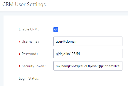
ACT! CRM
Configuration page of the ACT! CRM can be accessed via admin login, on the IPPBX Web GUI🡪Other Features🡪CRM”.
The configuration steps of the ACT! CRM are as follows:
- Navigate to Other Features🡪CRM and select the “ACT! CRM” option.
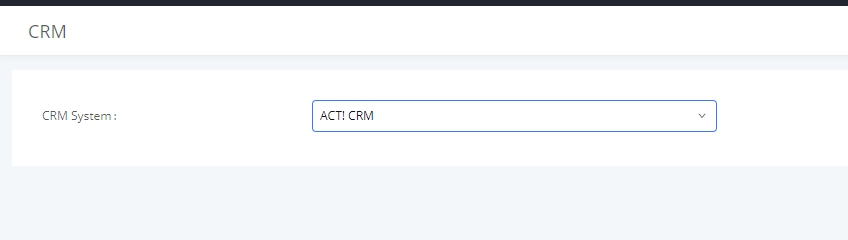
- Log into the IPPBX as a regular user and navigate to Other Features🡪CRM User Settings and check “Enable CRM” option and enter the username and password, which will be the ACT! CRM account’s API Key and Developer Key, respectively. To obtain these, please refer to the ACT! CRM API developer’s guide here: https://mycloud.act.com/act/Help
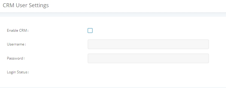
PMS
PBX supports Hotel Property Management System PMS, including check-in/check-out services, wakeup calls, room status, Do Not Disturb which provide an ease of management for hotel applications. This feature can be found on Web GUI🡪Integrations🡪PMS.
PMS API
The PMS API allows users to use their own middleware to work with PMS systems instead of currently supported integrations.
Additionally, this API allows access to read and modify certain IPPBX parameters that current supported PMS integrations cannot. To use this, users must first enable and configure the HTTPS API settings.
For more details, please refer to online https://documentation.grandstream.com/knowledge-base/https-api/, Pmsapi section.
Connecting to PMS
On the IPPBX WebGUI🡪Other Features🡪PMS🡪Basic Settings” set the connection information for the PMS platform.
Field | Description |
PMS Module | Users can select the desired PMS module from the drop-down list.
|
Wakeup Prompt | A customized prompts that can be played when the wakeup call is answered. To customize it please navigate to PBX Settings 🡪 Voice Prompt 🡪 Custom Prompt |
Username | This username is used to authenticate into the PMS API. |
Password | This password is used to autheticate into the PMS API. |
Back Up Voicemail Recordings | Back up voicemail recordings to external storage after check-out. |
Automatically Clear Wakeup Calls | Scheduled wakeup calls for rooms can be cleared upong checking in or checking out.
|
Automatically Clear Wave Chat History | If enabled, room Wave chat history will be automatically cleared upon check-in or check-out. |
Automatically Reset User/Wave Password | If enabled, the User/Wave password of the room extension will be automatically reset to a random password upon check-out. |
In order to use some PMS features please activate the feature code associated under “Call Features🡪Feature Codes”
- Update PMS Room Status
- PMS Wake Up Service
PMS Features
Room Management
In Room Management tab, the user can create a room and affect up to two extensions to it. This will appear in Room Status tab, and from there the user can change the Check-in/Check-out
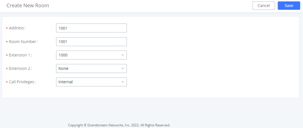
Call Privileges allows the administrator to set the level of call privilege of the room.
Room Status
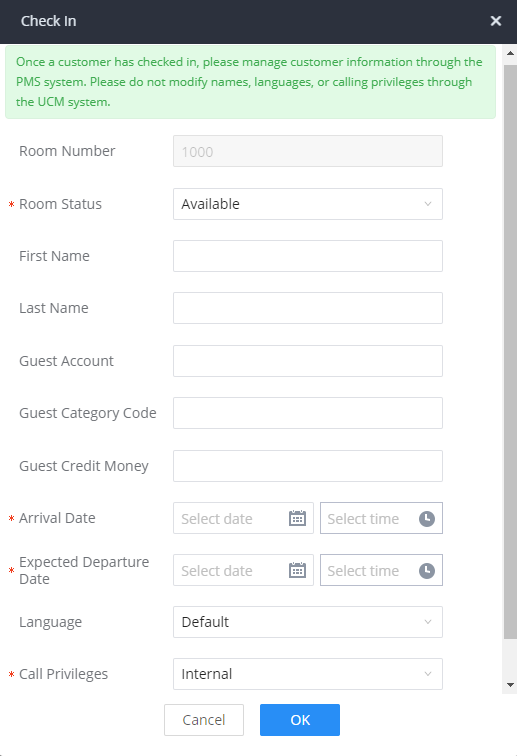
After clicking “OK” the client entry will be added to the list.
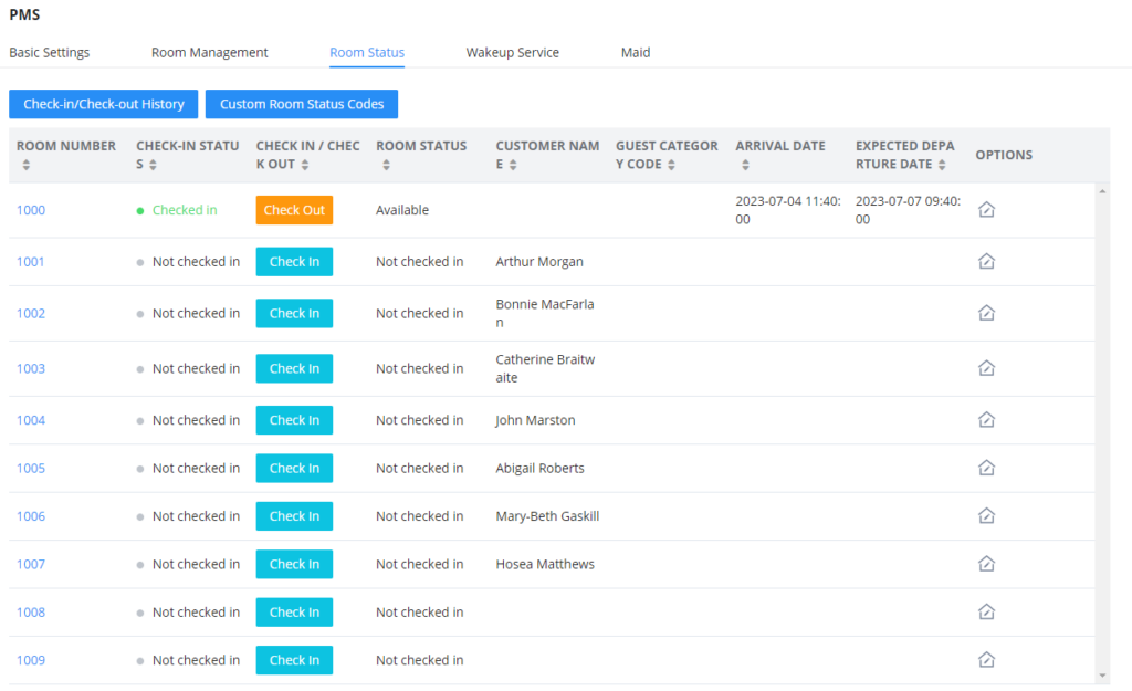
The user can click on Check-in/Check-out Records to view the history of the checked-in and checked-out guests.
Custom Room Status Codes
The user can customize the existing room statuses or add more statuses along with the corresponding name. The user can customize the status code to up to 16-digit code. To customize room status, please click on ![]() .
.
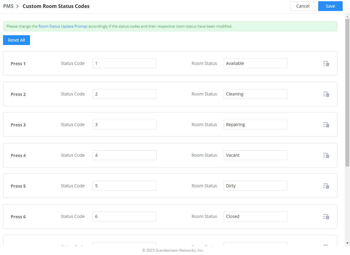
Wake Up Service
In order to create a New Wake up service, user can click on ”Add”, the following window will pop up:
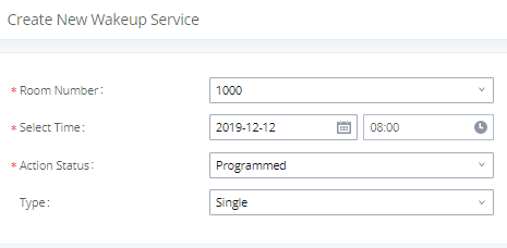
Field | Description |
Select the room number where to call with a limitation of 63 characters. | |
Select Time | Set the time of the wakeup call |
Show the status of the call:
Note: Editing an already executed wakeup service will automatically change the service’s status to “Programmed”. | |
Type |
|
Once the call is made on the time specified, the following figure show the status of the wakeup call.

This call has been executed but has been rejected, that why we can see the “Busy” status.
Housekeeper
In order to create a new housekeeper, click on ![]() under IPPBX WebGUI🡪Integrations🡪PMS🡪Housekeeper.
under IPPBX WebGUI🡪Integrations🡪PMS🡪Housekeeper.
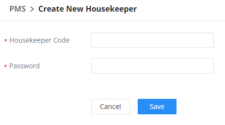
Housekeeper Code | Enter the Code to use when the houskeeper wants to change the status of the room. |
Password | Enter the password associated with the housekeeper. |
Local PMS
PBX offers a local Property Management System to give the user basic management features without having to purchase a PMS for the most basic property management actions. In addition to Room Management, Rooms Status for checking-in and checking-out, Wakeup Service, and Housekeeper functions, the PBX allows a number of additional functions upon checking-out, like backing up voicemail recordings, clearing wakeup calls and Wave history automatically, in addition to resetting Wave’s password. The user can use the Local PMS feature to check-in and check-out clients from the web user interface.
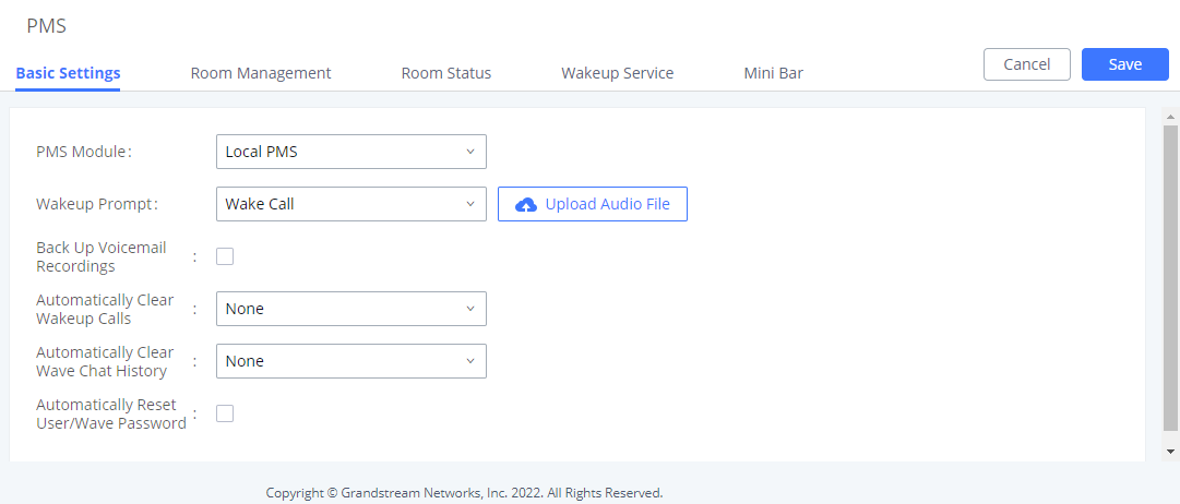
Field | Description |
PMS Module | Users can select the desired PMS module from the drop-down list.
|
Wakeup Prompt | A customized prompts that can be played when the wakeup call is answered. To customize it please navigate to PBX Settings 🡪 Voice Prompt 🡪 Custom Prompt |
Username | This username is used to authenticate into the PMS API. |
Password | This password is used to autheticate into the PMS API. |
Back Up Voicemail Recordings | Back up voicemail recordings to external storage after check-out. |
Automatically Clear Wakeup Calls | Scheduled wakeup calls for rooms can be cleared upong checking in or checking out.
|
Automatically Clear Wave Chat History | If enabled, room Wave chat history will be automatically cleared upon check-in or check-out. |
Automatically Reset User/Wave Password | If enabled, the User/Wave password of the room extension will be automatically reset to a random password upon check-out. |
QueueMetrics
The QueueMetrics docking tool provides an interface for IPPBX system and QM docking. Pass the IPPBX call queue report to QueueMetrics in a richer form. QueueMetrics is a call center control platform that supports login and logout of frequently used agents in the call center, provides call reports, real-time queue monitoring and other functions.
Parameter | Description |
Enable QueueMetrics Integration | Tick this box to enable QueueMetrics integration module. |
QueueMetrics URL | Enter the URL of the QueueMetrics on-premise server you have installed. (i.e. http://xxx.xxx.xxx.xxx:8080/queuemetrics.). |
Username | Please enter the username used to interface with QueueMetrics. This is typically the QueueMetrics webqloader user. Please confirm that the user is enabled to avoid connection failure. |
Webqloader Password | Please enter the webqloader password. |
Partition | Enter the data storage partition identifier |
Outbound Call Tracking | If enabled, QueueMetrics will track the outgoing calls of all extensions. Note: Outbound Call Tracking is available only on the UCM63XX. |
Google Services
Google Services integration allows integrating the PBX with Google Calendar to automatically synchronize the created Multimedia and Onsite Meetings schedule with Google Calendar of the host and the participants. In order to use this integration the user needs to enable API on Google Cloud Console and obtain the Client ID and the Client Secret, then enter the authorized redirect URIs.
Google Calendar Authorization
In Google Calendar Authorization configuration page, please enter the generated OAuth2.0 Client ID, OAuth2.0 Client Secret, and Authorized redirect URIs to integrate the PBX with Google Calendar.
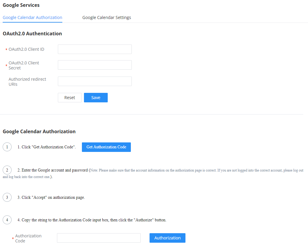
Google Calendar Settings
On Google Calendar Settings configuration page the user can enable “Google Calendar Auto Refresh Synchronization” to synchronize the meetings created automatically with Google Calendar. The user can also create a calendar label to mark different events on the calendar with customized labels.
To learn more about labels, please refer to the following link: https://support.google.com/calendar/answer/12377581
Wave Integration