


OVERVIEW
Overview Page
The overview page provides an overall view of the GCC601X(W)’s information presented in a Dashboard style for easy monitoring. Please refer to the figure and table below:
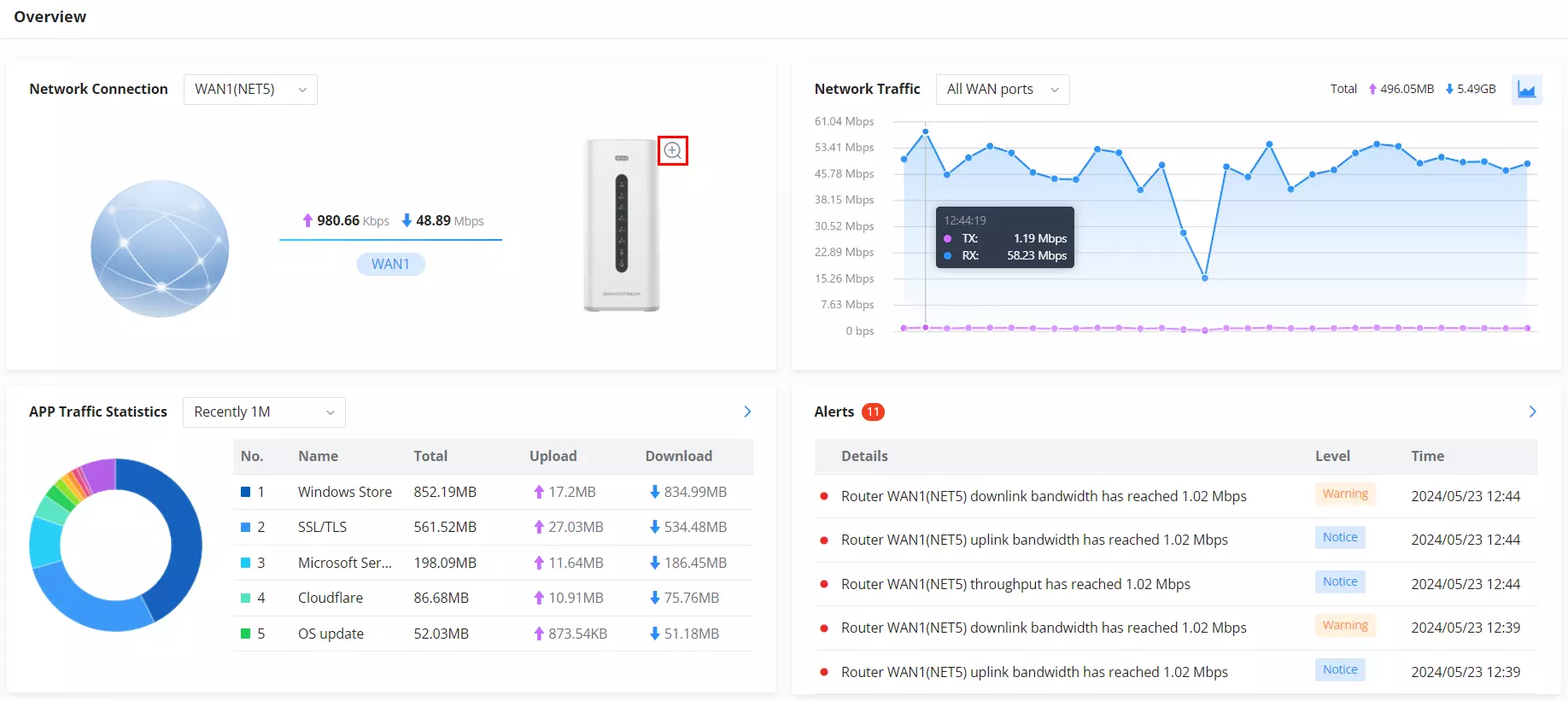
- Under Network Traffic and APP Traffic Statistics, users can hover the mouse cursor over the graphs to display more details.
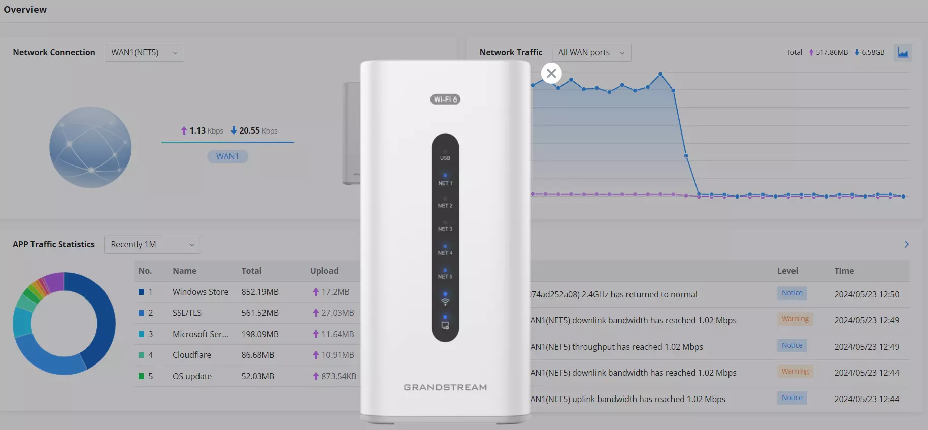
- Under Network Connection, users can click on the “Zoom icon” to display a virtual GCC device with live LED indicators.
Network Connection | Displays the current state of the network connection for the selected WAN port and shows the current upload and download speed. Note: the user can select the WAN port from the drop-down list. |
Network Traffic | Shows network traffic in real time. Note: the user can select the WAN port from the drop-down list or select All WAN ports. |
Alerts | Shows Alerts General, Important or Emergency with details and time. |
APP Traffic Statistics | Displays traffic statistics based on apps usage (%). |
Overview page
Port Info
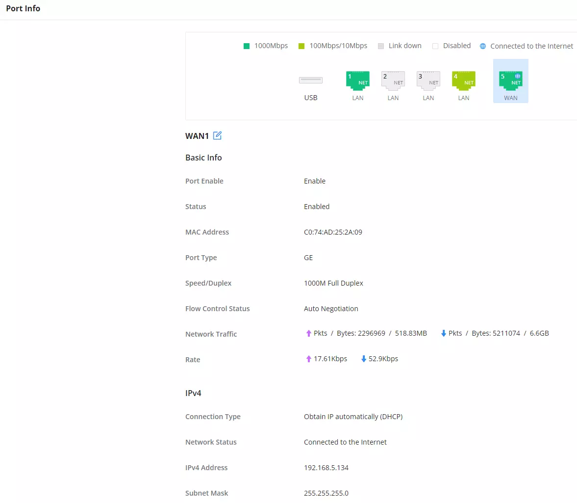
The Port Info page displays an overview of all port statuses, including the USB Port, Gigabit ports, and SFP ports, indicating the links up with a green color and links down with a grey color. Furthermore, the user can click on the port icon to get more info about the selected link; refer to the figure below:
Navigate to Overview → Port Info:
NETWORK SETTINGS
Port Configuration
To access port configuration, please access the user interface of the GCC601X(W) and then navigate to Network Settings → Port Configuration.
- Port Status
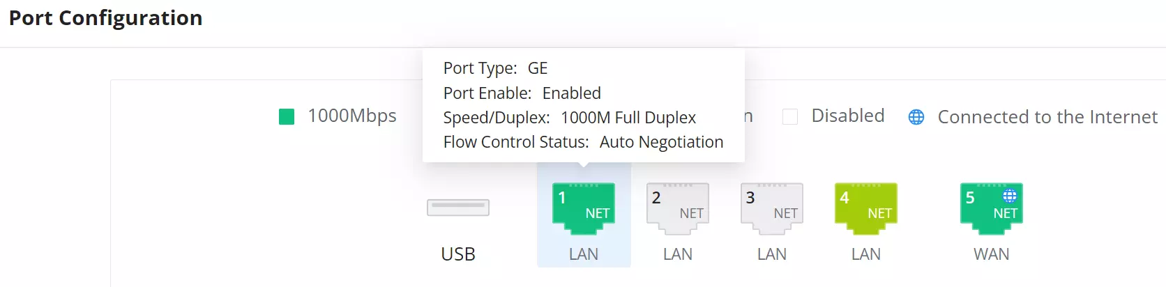
At the top, you can find the status of all the ports.
- Purple color: port speed is 2.5 Gbps (works only with SFP ports and 2.5 Gbps SFP module).
- Green color: port speed is 1 Gbps.
- Light green color: port speed is 100Mbps/10Mbps.
- Grey color: link down.
- White color: port disabled.
- Internet icon: port connected to the internet (for WAN ports).
- Port Configuration
The Port Configuration page allows the user to configure the settings related to all the ports, including the gigabit Ethernet ports (GE) and SFP optical ports. Editable settings include Port Name, Port Mode, Speed/Duplex, and Flow Control.
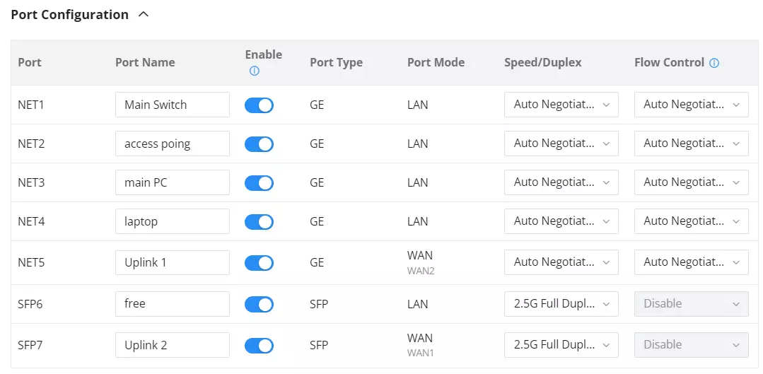
Port | This field indicates the port number. |
Port Name | This indicates the port name. |
Enabled | Toggle ON or OFF the port. Note: When set to disabled, this physical port is disabled and all port-based configurations do not take effect. |
Port Type | This field indicates the port type.
|
Port Mode | This indicates the port role.
|
Speed/Duplex | In this setting, the user can configure the duplex mode as well as the speed of the port. The duplex setting of the port can be set to: 1000M Full Duplex or 2.5G Full Duplex. When the mode is set to Auto Negotiation, the GCC device will determine based on the settings negotiated with the device connected. |
Flow Control | The user can enable or disable flow control using this option. Note: When the setting is set to Auto Negotiation, the GCC device will determine based on the settings negotiated with the device connected. |
Port configuration – part 2
- PoE Configuration
The user can also control the power limit on each PoE port of the GCC601X(W).
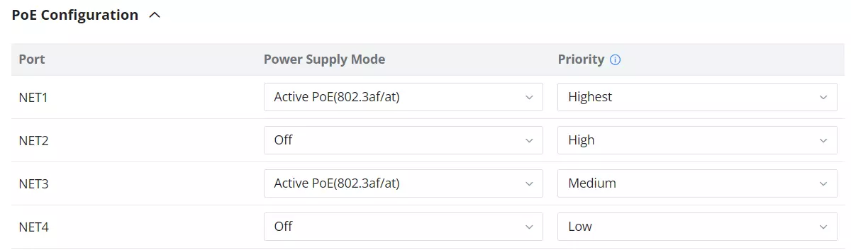
Port | This field indicates the port number. |
Power Supply Mode | This option configures the power supply mode for the port, there are two options:
|
Priority | Defines the power supply order for PoE ports when power is limited. The available priority levels are: – Highest – High – Medium – Low Note: Power is allocated based on the following rules: • Priority setting takes precedence — ports with higher priority (e.g., Highest) will always receive power before those with lower priority. • If multiple ports share the same priority, the system will prioritize the port with the lowest number (e.g., NET1 before NET5). • Only connected ports are considered — if some ports are disconnected, they are skipped entirely during power distribution. |
Port configuration – PoE configuration
WAN
WAN ports provide uplink connectivity to the Internet or an upstream network. The WAN ports can be connected to a DSL modem or another router, and they support configuring static IPv4/IPv6 addresses as well as PPPoE.
On supported models, the USB port can also be used as a WAN interface by selecting USB in the Port field and connecting a compatible USB 4G/5G dongle to the device.
For the list of USB 4G/5G dongles that have been tested and verified, refer to USB 4G/5G Dongle Compatibility on the Grandstream Documentation Portal.
On this page, the user can modify the settings for each WAN port, delete existing WAN ports, or add new WAN ports. Adding a WAN port will reduce the number of available LAN ports. When there is more than one WAN port, load balancing or backup (Failover) can be configured between multiple WAN ports.
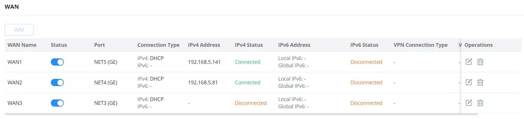
Click the “Add” button to add another WAN port or click the “edit icon” to edit the previously created ones.
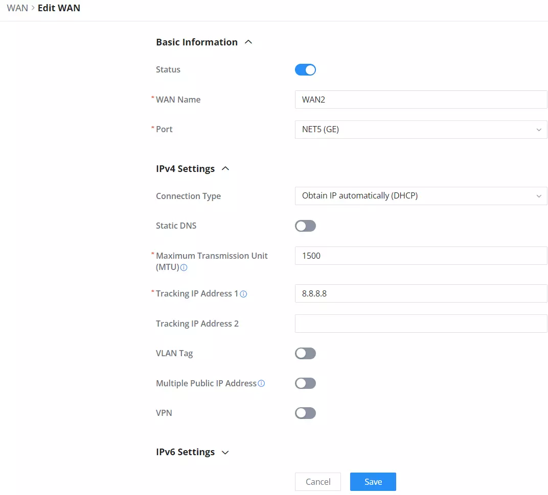
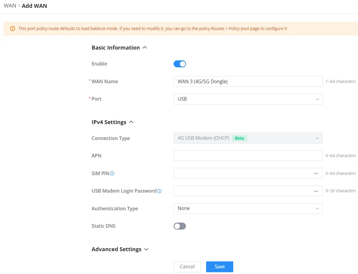
Please refer to the following table for network configuration parameters on the WAN port.
Basic Information | |
Enable | Click to enable or disable the WAN |
WAN Name | Enter a name for the WAN port |
Port | Select from the drop-down list the port to be used as a WAN. |
IPv4 Settings | |
Connection Type |
The default setting is “Obtain IP automatically (DHCP)”. |
Static DNS | Toggle ON or OFF to enable or disable static DNS |
APN | Access Point Name provided by the mobile operator for data services. Note: Displayed only when the Connection Type is 4G USB Modem (DHCP). |
SIM PIN | PIN code configured on the SIM card (if any). Multiple incorrect PIN attempts can cause the SIM card to be locked (PIN lock). Note: Displayed only when the Connection Type is 4G USB Modem (DHCP). |
USB Modem Login Password | Optional login information required by some USB modems / operators for management or authentication. Note: Displayed only when the Connection Type is 4G USB Modem (DHCP). |
Authentication Type | Authentication method used for the mobile data session.
Select the method required by the mobile operator. Note: Displayed only when the Connection Type is 4G USB Modem (DHCP). |
Preferred DNS Server | Enter the preferred DNS Server, ex: 8.8.8.8 |
Alternative DNS Server | Enter the altenative DNS Server, ex: 1.1.1.1 |
VPN | Toggle ON or OFF to enable or disable VPN |
VPN Connection Type |
|
Username | Enter the username to authenticate into the VPN server. |
Password | Enter the password to authenticate into the VPN server. |
Server Address | Enter the IP address or the FQDN of the VPN server. |
MPEE Encryption (if PPTP is selected) | When PPTP is chosen as the VPN Connection Type, the user can choose to toggle on or off the MPEE Encryption. |
IP Type |
|
IP Address | If IP Type is set to Static IP, specifies the static IP address. |
Subnet Mask | If IP Type is set to Static IP, specifies the subnet mask. |
Default Gateway | If IP Type is set to Static IP, specifies the default gateway. |
VPN Static DNS | Enable this option to use the statically assigned DNS server addresses. |
Preferred DNS Server | If VPN Static DNS is enabled, specifies the preferred DNS server. |
Alternative DNS Server | If VPN Static DNS is enabled, specifies the alternative DNS server. |
Maximum Transmission Unit (MTU) | This configures the value of the maximum transmit unit. The valid range for this value is 576 – 1460. Note: Please do not change this value unless it’s necessary. |
IPv6 Settings | |
IPv6 | Enable this option to use IPv6 on this specific WAN port. |
Connection Type |
|
IPv6 Address/Prefix Length | When the Connection Type is set to Static IP, the user can enter the static IP address and prefix length. Note: This option appears only when the Connection Type is set to Static IPv6. |
IPv6 PD/Prefix Length | When the Connection Type is set to Static IP, the user can enter the IPv6 PD and prefix length. Note: This option appears only when the Connection Type is set to Static IPv6. |
Default Gateway | Enter the IP address of the default gateway Note: This option appears only when the Connection Type is set to Static IPv6. |
Static DNS | Enable this option to enter statically assigned DNS. Note: This option appears only when the Connection Type is set to DHCPv6. |
Preferred DNS Server | Enter the IP address of the preferred DNS server. Note: This option appears only when the Connection Type is set to Static IPv6. |
Alternative DNS Server | Enter the IP address of the alternative DNS server Note: This option appears only when the Connection Type is set to Static IPv6. |
IPv6 Relay to VLAN | Once enabled, relay IPv6 addresses to clients on the LAN side. Note: This function will take effect only “IPv6 Relay from WAN” is enabled on VLAN. |
Advanced Settings | |
Maximum Transmission Unit (MTU) | Configures the maximum transmission unit allowed on the wan port.
|
WAN Port MAC Address | Select the MAC address of the WAN port from the drop-down list:
|
Use default MAC address | Shows the default MAC address if the option Use default MAC address is selected. |
Custom MAC Address | Enters the custom MAC address if the option Use custom MAC address is selected. |
Tracking IP Address 1 | Configures tracking IP address of WAN port to determine whether the WAN port network is normal. Note: to modify this configuration item, enter a stable and pingable host IP. If the IP address of the host entered is unstable or cannot be pinged, a network exception may be caused. |
Tracking IP Address 2 | Add another alternative address for Tracking IP Address |
VLAN Tag | Toggle ON or OFF to enable or disable VLAN Tag |
VLAN Tag ID | Enter the VLAN Tag ID with the priority Notes: • Priority is 0~7 with 7 being the highest priority. Default is 0. • Multiple WANs can use the same VLAN ID. |
Bridge mode | oggle ON to enable Bridge Mode, which allows the WAN port to act as a bridge between specific VLANs. |
VLAN Tag ID/Port/Priority | • Enter the VLAN Tag ID and assign a port for traffic bridging. |
Multiple Public IP Address | Toggle ON or OFF to enable or disable Multiple Public IP Address Note: Please use with Port Forward function, so that you can access to router via public IP address. |
Public IP Address | Enter a public IP address Note: Click on “Plus” or “minus” icons to add or delete public IP addresses. |
WAN Settings
Bridge Mode
Overview:
Bridge Mode allows VLAN-tagged WAN traffic to be mapped directly to specific LAN ports, enabling seamless passthrough of ISP-provided services. This is commonly used in multi-service deployments such as Triple Play setups, where Internet, IPTV, and VoIP services are separated using VLANs and assigned to designated ports.
Users can configure multiple VLAN Tag IDs, assign each to a port, and define priority levels (0-7) for QoS handling. Each port can only be bridged by one WAN interface.
Navigation:Network Settings → WAN → Add/Edit WAN → Scroll to Bridge Mode under Advanced Settings.
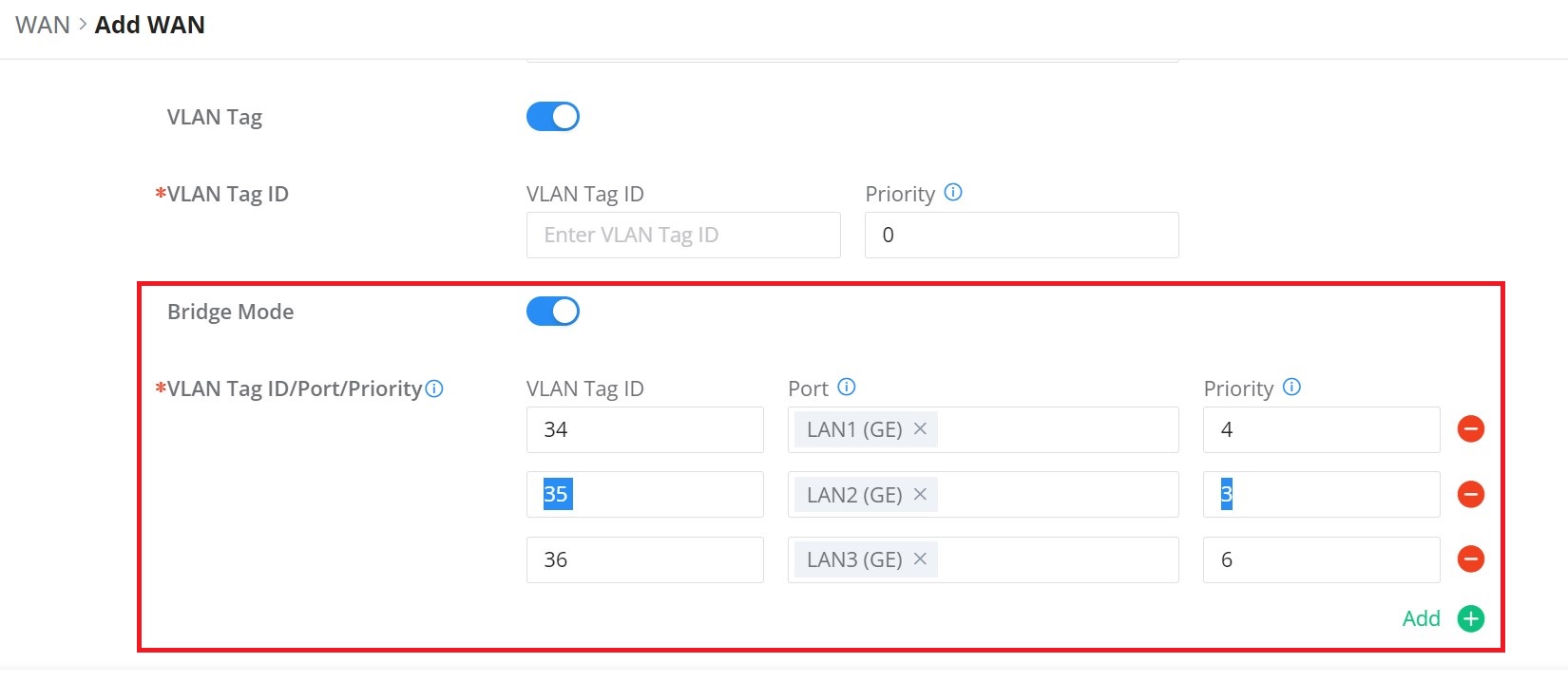
| Field | Description |
|---|---|
| Bridge Mode | Toggle to enable bridging of VLAN-tagged traffic to LAN ports. |
| VLAN Tag ID | Enter the VLAN ID provided by the ISP for service separation. |
| Port | Select the LAN/SFP port to map the VLAN traffic. Each port can only be assigned once. |
| Priority | Set traffic priority (0–7), where 7 is the highest. Used for QoS handling. |
| Add / Remove | Add multiple VLAN-to-port mappings or remove existing ones. |
Notes:
- This feature is typically configured based on ISP instructions.
- Ensure VLAN IDs and port assignments align with your service provider’s requirements.
- Priority settings optimize traffic flow for services like VoIP or IPTV.
LAN
To access the LAN configuration page, log in to the GCC601x(w) WebGUI and go to Network Settings → LAN. VLAN configuration, such as adding VLANs or setting up a VLAN port, can be found here on this page, as well as the ability to add Static IP Bindings, local DNS Records, and Bonjour Gateway.
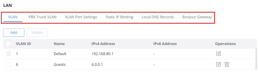
VLAN
GCC601X(W) integrates VLAN to enhance security and add more functionalities and features. VLAN tags can be used with SSIDs to separate them from the rest. Also, the user can allow these VLANs only on specific LANs for more control and isolation, and they can be used as well with policy routing.
- Add or Edit VLAN
To add or edit a VLAN, navigate to Network Settings → LAN. Click the “Add” button or click the “Edit” icon.
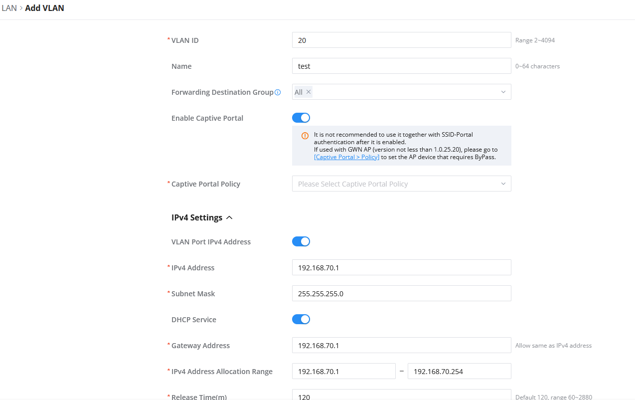
VLAN ID | Enter a VLAN ID Note: VLAN ID range is from 2 to 4094. |
Name | Enter the VLAN name |
Forwarding Destination Group | By default, “All” is selected, and the interfaces set in the default rule of the policy pool (WAN or VPN) are selected by default and cannot be unchecked here, and subsequent new interfaces are automatically included. |
Enable Captive Portal | Toggle this option to activate Captive Portal authentication for devices connected through this VLAN. It is not recommended to enable this alongside SSID-Portal authentication. |
Captive Portal Policy | Select the Captive portal policy from the drop-down list or click on “Add Policy ” to add a new one. |
IPv4 Settings | |
VLAN Port IPv4 Address | Toggle ON/OFF to enable or disable the use of the IPv4 address. |
IP Address | Enter the IPv4 address of the VLAN interface. |
Subnet Mask | Enter the subnet mask of the VLAN. |
DHCP Service | Toggle the button to enable DHCP service on this VLAN. |
Gateway Address | When DHCP Service is enabled, enter the gateway address to be provided to DHCP clients on this VLAN. |
IPv4 Address Allocation Range | When DHCP Service is enabled, enter the range of IPv4 addresses that can be assigned to clients on this VLAN. |
Release Time(m) | Enter the DHCP lease time in minutes. |
DHCP Option | Configure DHCP options to provide additional configuration parameters to DHCP clients. Up to 32 DHCP options can be configured.
|
Preferred DNS Server | Enter the preferred DNS server address to be provided to DHCP clients. |
Alternative DNS Server | Enter the alternative DNS server address to be provided to DHCP clients. |
IPv4 Routed Subnet | Toggle the button to allow hosts on this VLAN to access the Internet through the WAN interface. |
Interface | When IPv4 Routed Subnet is enabled, select the WAN interface through which hosts on this VLAN access the Internet. |
IPv6 Settings | |
VLAN Port IPv6 Address | Toggle ON/OFF to enable or disable the use of the IPv6 address. |
IPv6 Address Source | Select the WAN port from which the IPv6 address prefix is obtained. |
IPv6 Address Prefix / Prefix Length | Enter the IPv6 address prefix and prefix length. |
Interface ID | Toggle ON or OFF the interface ID |
Customize Interface ID | Enter the interface ID |
IPv6 Preferred DNS Server | Enter the IPv6 Preferred DNS Server |
IPv6 Alternative DNS Server | Enter the IPv6 Alternative DNS Server |
IPv6 Relay form WAN | Once enabled, clients will get IPv6 addresses directly from the WAN side. Note: This function will take effect only “IPv6 Relay to VLAN” is enabled on the WAN side. |
IPv6 Address Assignment | Select from the drop-down list the IPv6 address assignment
|
Add/Edit VLAN
PBX VLAN
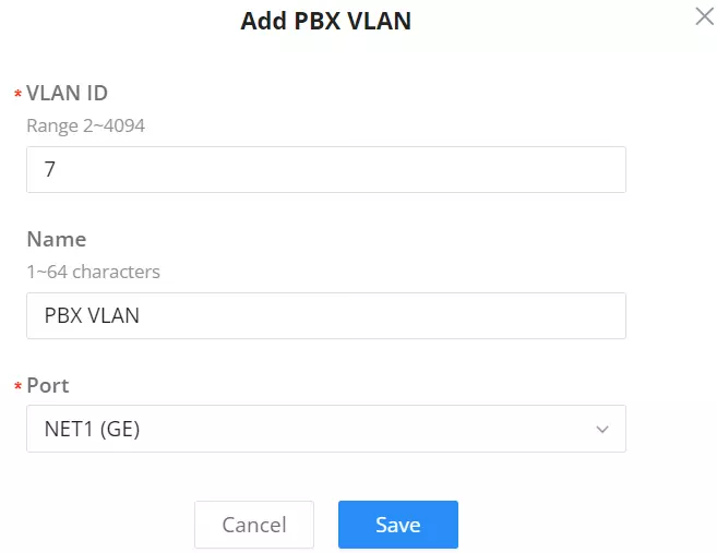
PBX VLAN allows creating an interface to connect the GCC device to an ITSP through a SIP Trunk. The interface is segregated using a VLAN, however, no VLAN tagging/untagging is occurring beyond the interface. When creating a PBX VLAN, choose the VLAN ID, then specify the port of the PBX VLAN. On the PBX module, specify the IP address and mask for the interface, then specify the gateway. These options should be provided by the ITSP and set statically on the interface. For more information, please refer to the following sections of the GCC PBX documentation to learn how to configure a SIP trunk using PBX VLAN in the following link.
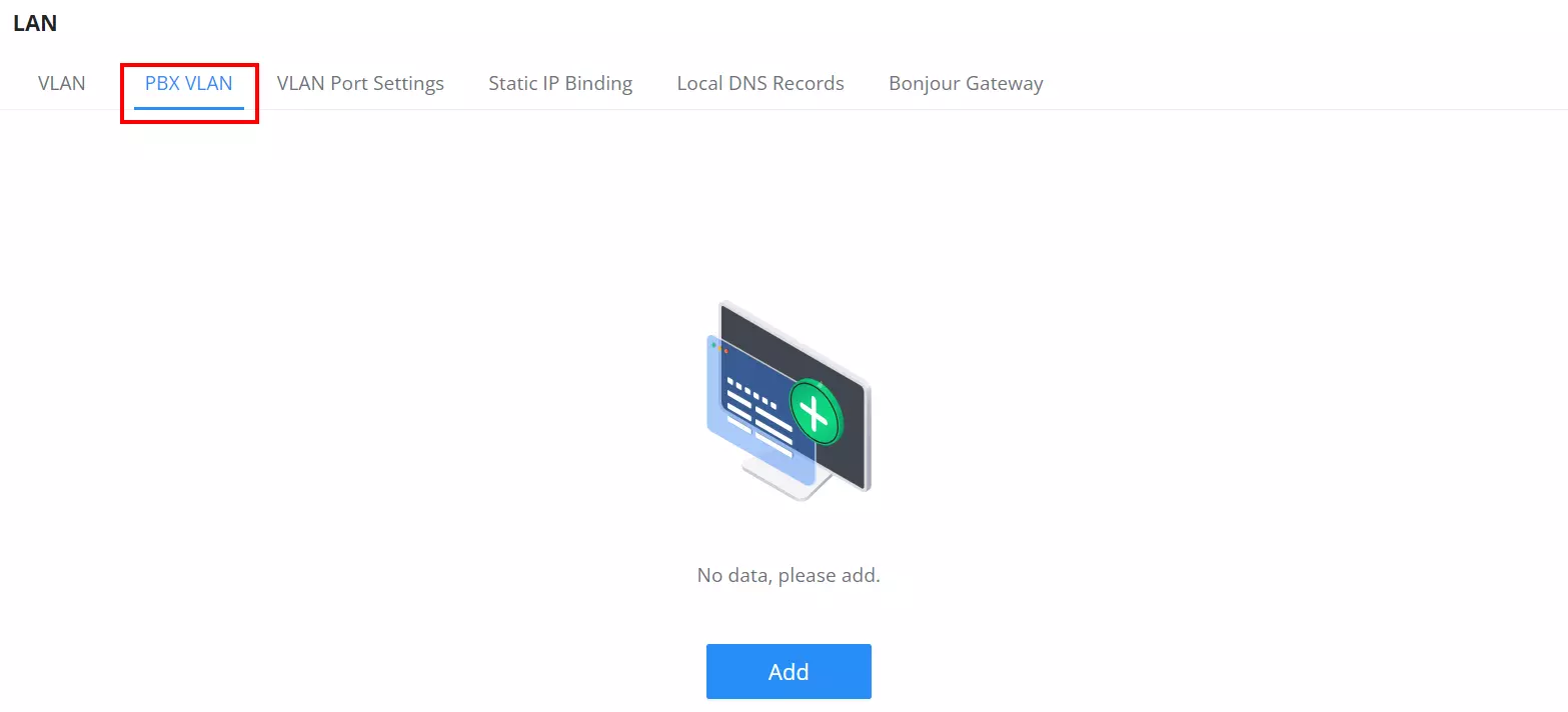
To add a PBX VLAN, navigate to the Networking module → Networking Settings → LAN page → PBX VLAN tab. Click the “Add” button to add a PBX VLAN.
Specify a VLAN ID, name and then select the port as shown below:
VLAN Port Settings
The user can use LAN ports to allow only specific VLANs on each LAN port, and in case there are more than one VLAN, then there is an option to choose one VLAN as the default VLAN ID (PVID or Port VLAN Identifier). Click the “Edit icon” to edit the VLAN Port Settings or click the “Delete icon” to delete that configuration and bring back the default settings which is by default VLAN 1.
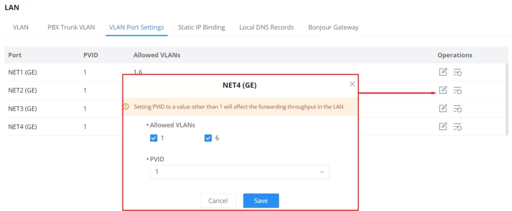
| Allowed VLANs | Choose the VLANS to be allowed on this port. |
| PVID | Select the Port VLAN Identifier or the default VLAN ID |
Static IP Binding
The user can set static IP binding to devices in which the IP address will be bound to the MAC address. Any traffic that is received by the router that does not have the corresponding IP address and MAC address combination will not be forwarded.
To configure Static IP Binding, please navigate to Network Settings → LAN → Static IP Binding, refer to the figure and table below:
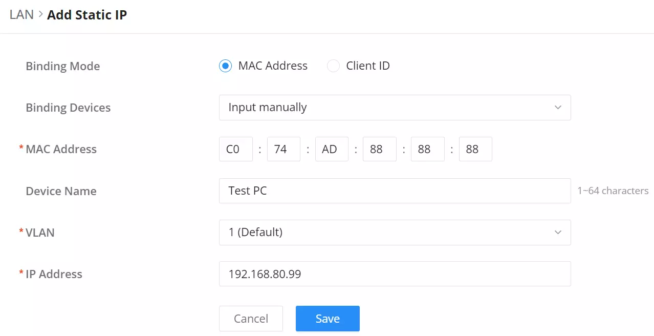
Binding Mode | select the binding mode, either using the client MAC address or Client ID. |
Binding Devices | Select the device MAC address from connected devices list. Note: only available bindind mode is set to MAC Address. |
Client ID Type | Select the client ID type, either based on:
Note: only available bindind mode is set to Client ID. |
MAC Address | Enter the MAC Address Note: only available bindind mode or Client ID Type is set to MAC Address |
ASCII | Enter the ASCII Note: only available Client ID Type is set to ASCII |
Hex | Please enter XX:XX:XX:XX format or a valid even-digit hexadecimal number string, the first two digits need to enter the type value. Note: only available Client ID Type is set to Hex |
Device Name | Enter a name for the device |
VLAN | Select the VLAN ID to assign to the bound device. This ensures the device operates under the configured VLAN policies. |
IP Address | Enter the static IP address to assign it to the selected device. |
Static IP Binding
Local DNS Records
Local DNS Records is a feature that allows the user to add DNS records into the GCC601X(W), which can be used to map the domain name to an IP address. This feature can be used when the user needs to access a specific server using a domain name instead of an IP address, and when they do not want to include the entry in public DNS servers. To add a local DNS record, please navigate to Network Settings → LAN → Local DNS Records, then click “Add“
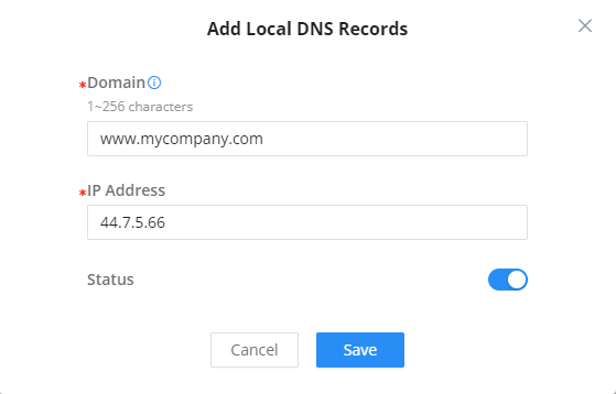
- Enter the domain name in “Domain“
- Then, enter the IP address to which the domain name will be mapped to.
- Toggle on the “Status” for the mapping to take effect.
Bonjour Gateway
The Bonjour service is a zero-configuration network that enables the automatic discovery of devices and services on a local network. For example: it can be used on a local network to share printers with Windows® and Apple® devices.
Once enabled, Bonjour services (such as Samba) can be provided to Bonjour-supporting clients under multiple VLANs. Once enabled, configure the services of the VLANs and proxies that need to intercommunicate.
To start using Bonjour Gateway, toggle ON the service first, then select the VLAN, the services, and the operational mode as shown below:
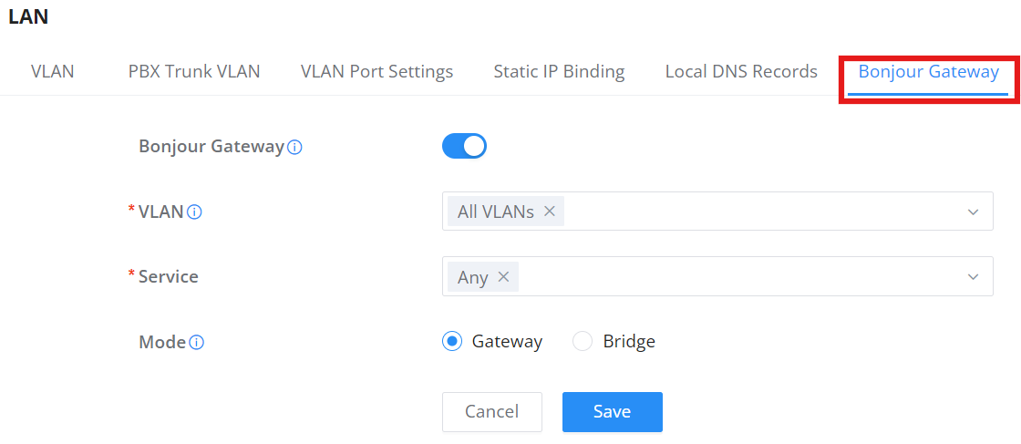
- Bonjour Gateway: Toggle to enable or disable mDNS discovery across VLANs.
- VLAN: Select the specific VLANs that require intercommunication.
- Service: Select the specific services to be discovered (e.g., AirPlay, AirPrint, Chromecast, Samba).
- Mode: Choose how the router handles the discovery packets between networks.
| Mode | Description |
| Gateway | The router proxies mDNS packets and rewrites the source IP address to the router’s gateway IP. |
| Bridge | The router transparently forwards mDNS packets without modifying the packet content. |
IGMP
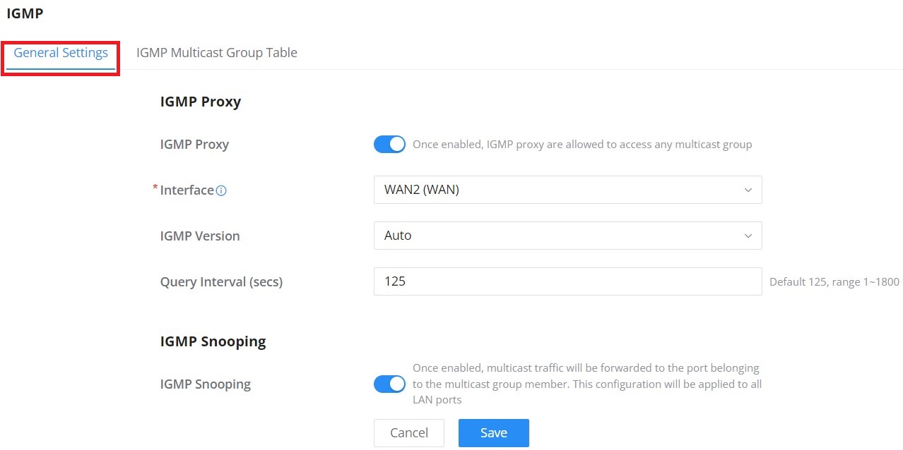
When IGMP Proxy is enabled, the GWN router can issue IGMP messages on behalf of the clients behind it; then the GCC601X(W) will be able to access any multicast group.
To start using IGMP Proxy:
- Toggle ON IGMP Proxy first.
- Select the WAN interface to be used from the drop-down list (Note: IGMP Proxy cannot be enabled on a WAN port with bridge mode enabled)
- Select the version, be default is Auto.
The user can also enable IGMP Snooping. Once enabled, multicast traffic will be forwarded to the port belonging to the multicast group member. This configuration will be applied to all LAN ports.
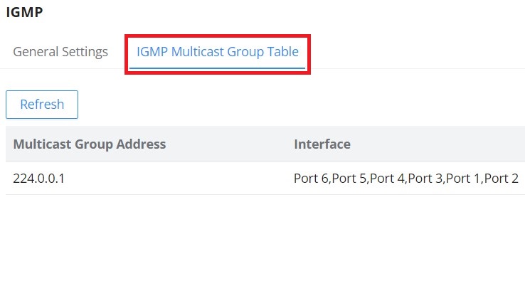
On the IGMP Multicast Group Table, all the active multicast groups will be displayed here.
Network Acceleration
Network acceleration allows the GCC601X(W) to transfer data at a higher rate when Hardware acceleration is enabled. This ensures high performance.
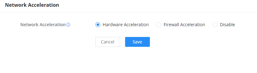
- Hardware Acceleration: All the network traffic will use dedicated hardware acceleration. Once enabled, QoS, rate limit, and traffic statistics will not take effect.
- Firewall Acceleration: Only IDS/IPS and app traffic authorized by the firewall will use dedicated hardware acceleration. Once enabled, QoS rate limit will not take effect.
VPN
VPN stands for “Virtual Private Network”, and it encrypts data in real time to establish a protected network connection when using public networks.
VPN allows the router to be connected to a remote VPN server using PPTP, IPSec, L2TP, OpenVPN®, ZeroTier, and WireGuard® protocols, or configure an OpenVPN® server and generate certificates and keys for clients.
GCC6000 series devices support the following VPN functions:
- PPTP: Client and server
- IPSec: Site-to-site and client-to-site
- OpenVPN®: Client and server
- ZeroTier: Client
- L2TP: Client
- WireGuard®: Server
Protocol Overviews:
- OpenVPN®: Secure, open-source VPN protocol suitable for cross-platform connections (Windows, Mac, Android, iOS). Supports certificate-based authentication and is ideal for remote workforce access or site-to-site encryption over public networks.
- ZeroTier: Provides seamless LAN-like connectivity over the internet using peer-to-peer tunnels, bypassing NAT and firewall complexity without additional network configuration.
- WireGuard®: Lightweight and modern protocol with fast setup and minimal overhead. Ideal for mobile users or low-resource devices. Supports quick configuration export for peers.
- IPSec (Site-to-Site): Enterprise-grade encryption standard. Suitable for building permanent tunnels between two fixed locations (e.g., HQ ↔ Branch). Supports dynamic IP updates and hardware acceleration.
- PPTP: Legacy protocol with broad compatibility. Easy to configure but not recommended for high-security needs. Best for internal or low-risk use cases.
For more details on how to configure each VPN protocol separately, please refer to the guides below:
- OpenVPN®
- L2TP
- PPTP Guide
- WireGuard®
- IPSec
- ZeroTier
VPN page can be accessed from the Networking module Web GUI → VPN.
Setup Wizard
The main purpose of the Setup Wizard is to help users quickly and efficiently configure VPNs like WireGuard®, IPSec, OpenVPN®, ZeroTier, PPTP, and L2TP. It allows you to configure VPN connections with minimal manual input by automating most of the necessary steps and parameters. This makes it particularly useful for users who may not be familiar with more advanced networking settings.
- Easy Deployment: The wizard simplifies VPN deployment, supporting various networking scenarios, including both client-to-site and site-to-site connections.
- Predefined Configuration: Users can select from predefined VPN options, such as WireGuard®, IPSec, OpenVPN®, etc., based on their needs. Each type of VPN comes with different available scenes and configurations.
Purpose: The primary goal of this wizard is to make VPN setup faster and easier by automating many of the common settings. This reduces the likelihood of misconfigurations and ensures a smoother setup experience, especially for users who may not have in-depth knowledge of VPN protocols.
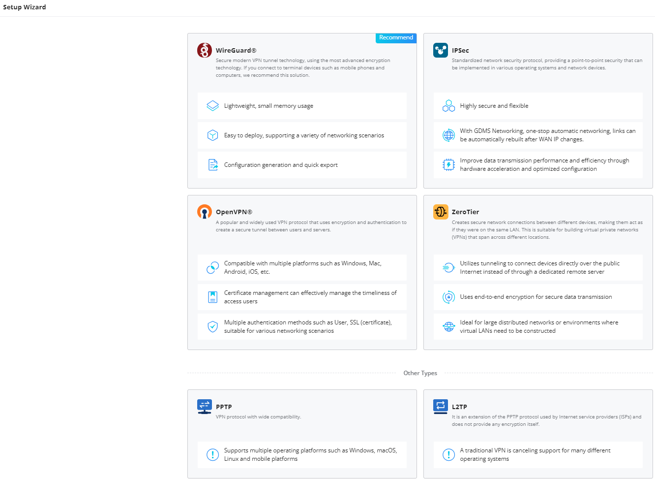
Relation to Manual Configuration: It’s important to note that the VPN Setup Wizard mirrors the same configuration process as manually configuring VPNs, but in a more user-friendly way. Advanced users can still manually configure VPNs if needed, but for most users, the wizard offers a more accessible method.
VPN-Type Specific:
The wizard is tailored for each VPN type. For instance:
- WireGuard®: Prioritizes fast, low-latency connections with a simple and secure setup.
- IPSec: Provides robust encryption and secure communication for both site-to-site and client-to-site scenarios.
- OpenVPN®: Allows more customizable security options, such as user-based certificate management and SSL encryption.
- ZeroTier: Creates secure peer-to-peer tunnels over the Internet, allowing remote devices to behave as if they’re on the same LAN. Ideal for building virtual LANs across distributed environments without relying on dedicated servers.
- PPTP/L2TP: While legacy protocols, these are supported for backward compatibility with older devices and systems.
By following this wizard, users can rapidly configure the required VPN connections without needing to navigate complex settings manually, making it an ideal solution for businesses looking to enhance security without complexity.
- WireGuard® Setup Wizard
WireGuard uses fewer parameters for faster setup. You’ll be prompted to:
- Name the connection
- Choose the router and WAN interface
- Assign the local IP and subnet
For advanced features like Peers and Remote Clients, refer to WireGuard® Manual Configuration.

- IPSec Setup Wizard
Designed for secure office-to-office tunnels. Simply select the Site-to-Site mode, and the wizard handles tunnel basics like endpoint roles and tunnel IPs.
Why use this:
- Ideal for permanent, encrypted connections between two static sites
- Supports automatic rebuild after WAN IP changes
For detailed control and manual tuning, see IPSec Site-to-Site Setup.

- OpenVPN® Setup Wizard
Choose between:
- Client-to-Site – For remote users to connect securely to a central office.
- Site-to-Site – To connect two office networks over the internet.
Once selected, the wizard will guide you through server selection, certificate management, and encryption options.
For advanced configuration, refer to OpenVPN® Manual Setup.

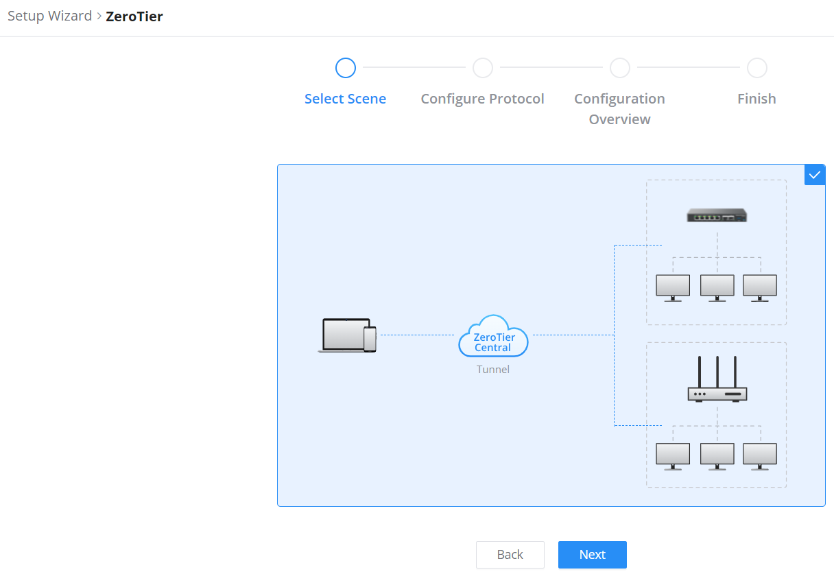
- ZeroTier
ZeroTier is available as a selectable VPN type in the Setup Wizard.
Choose this option to create a secure virtual network overlay between distributed devices using ZeroTier Central as the orchestrator. It simplifies peer-to-peer connections across NAT, firewalls, and different networks.
For full configuration steps, see ZeroTier VPN
- PPTP Setup Wizard
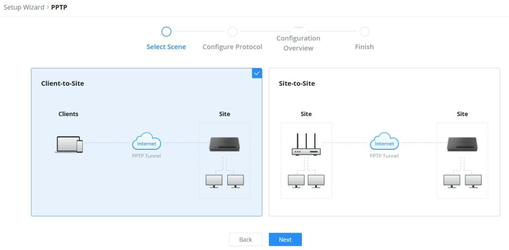
Choose:
- Client-to-Site – For basic remote user access
- Site-to-Site – For simple office-to-office bridging
PPTP is the easiest to set up, but less secure. Only use it in trusted environments or for quick internal access.
For more configuration options, refer to PPTP Setup.
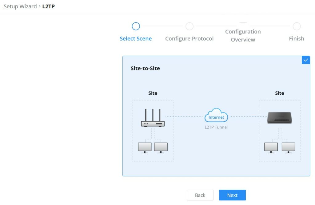
- L2TP Setup Wizard
Designed for simple site-to-site tunnels over the internet. Select Site-to-Site mode, and the wizard will guide you through configuring endpoints and authentication settings.
Why use this:
- Suitable for connecting two office networks through an L2TP tunnel.
- Useful in environments where legacy VPN compatibility is required.
For detailed configuration and advanced options, see L2TP Setup.
WireGuard®
WireGuard® is a free, open-source VPN solution that offers high performance, ease of use, and robust security for encrypting virtual private networks. The GCC6000 series routers support WireGuard® VPN with features like automatic client generation and QR code scanning for easy setup on mobile devices and other devices with camera support. WireGuard® can be configured to create Peers for Site-to-Site connections or to establish clients for terminal devices, such as mobile phones and computers.
To start using WireGuard® VPN, please navigate to Web UI → VPN → WireGuard® page. Click the “Add” button to add a WireGuard® server as shown below:

Please refer to the figure and table below when filling out the fields.
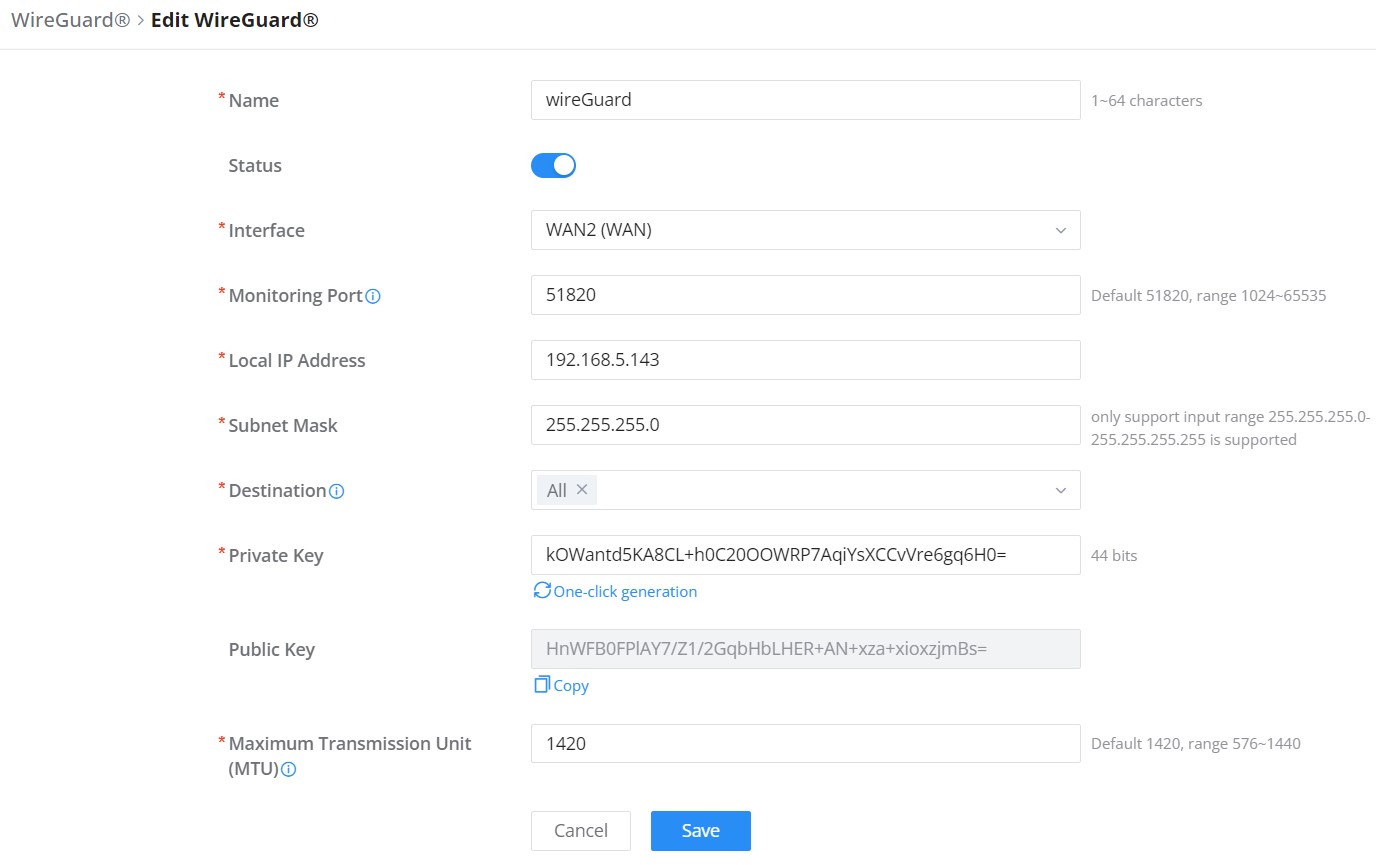
Name | Specify a name for Wireguard® VPN. |
Status | Toggle ON or OFF to enable or disable the Wireguard® VPN. |
Interface | Select from the drop-down list the WAN port. |
Monitoring Port | Set the local listening port when establishing a WireGaurd® tunnel. Default: 51820 |
Local IP Address | Specify the network that WireGuard® clients (Peers) will get IP address from. |
Subnet Mask | Configures the IP address range available to the Peers. |
Destination | Select the Destination(s) from the drop-down list. Note: When selecting “All”, subsequent new interfaces will be automatically included. |
Private Key | Click on “One-Click Generation” text to generate a private key. |
Public Key | The public key will be generated according to the private key. Click on “Copy” text to copy the public key. |
Maximum Transmission Unit (MTU) | This indicates the size of the packets sent by the router. Please do not change this value unless necessary. By default is 1450. |
Add/Edit WireGuard®
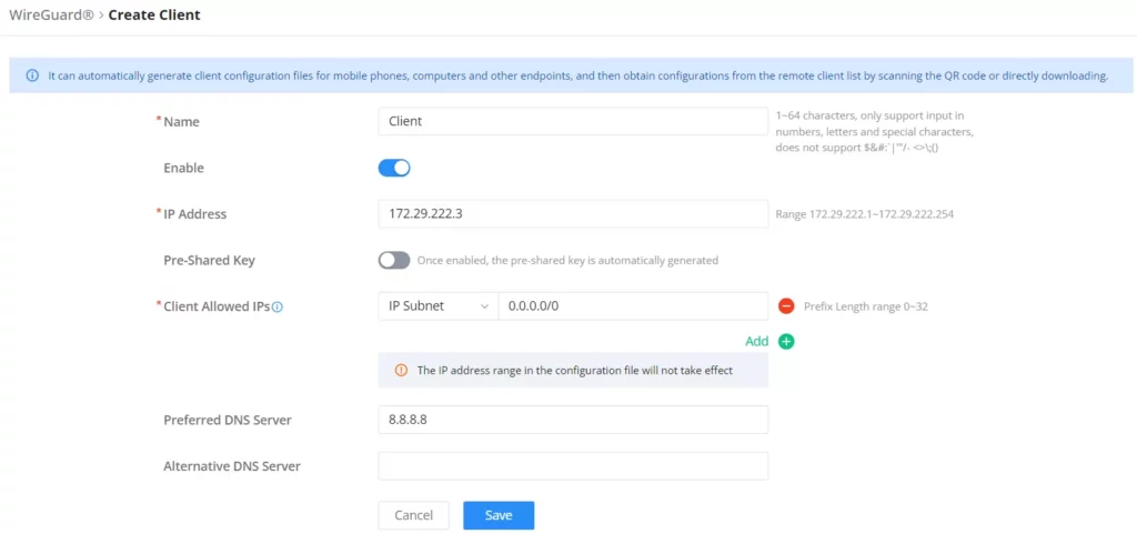
Once finished configuring WireGuard®, click the ” Add client” icon to generate clients very quickly and easily as shown in the figures below:

Enter a name and toggle status ON, then click the “Save” button.
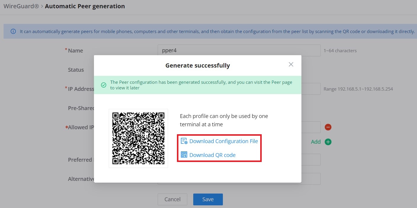
Now, the user can either download the configuration file and share it, or download a QR code for devices like mobile phones to scan.
For more details, refer to this guide: WireGuard® Site-to-Client.
Peers
On the Peers tab, users can create Site-to-Site connections by clicking the ‘Add‘ button to configure new WireGuard peers.
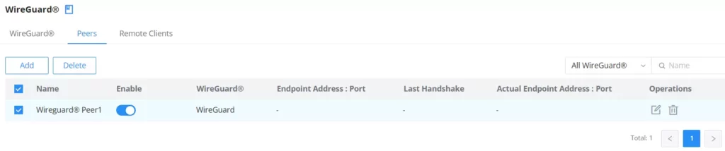
for more details, refer to this guide: WireGuard® Site-to-Site.
Please refer to the figure below when filling out the fields.
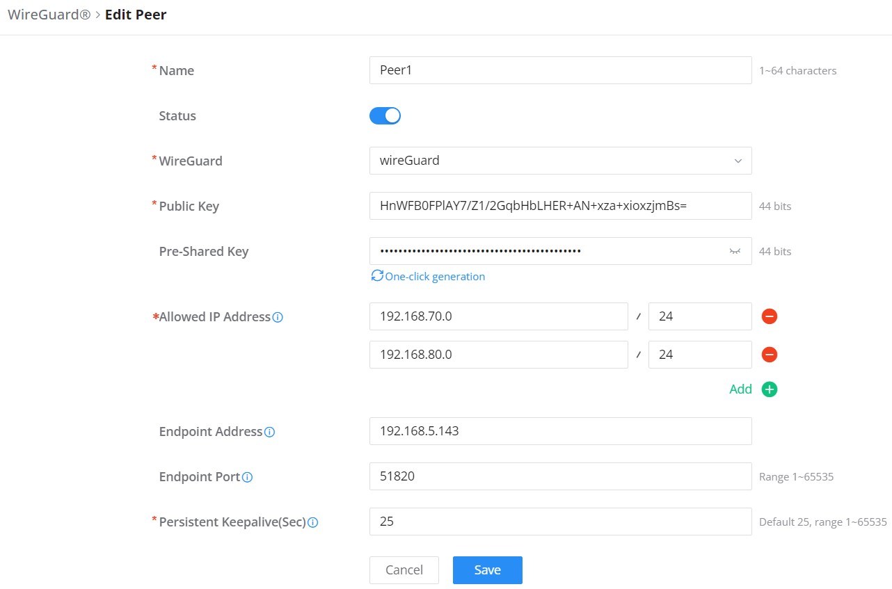
Field | Description |
Name | Define a name for the peer (1-64 characters). |
Enable | Toggle to enable or disable the peer connection. |
WireGuard® | Select the WireGuard® instance associated with this peer. |
Public Key | Enter the public key of the remote peer (44 bits). |
Pre-Shared Key | (Optional) Enter a pre-shared key for additional security (44 bits). |
Allowed IP Address | Specify the IP ranges allowed to communicate through this peer (CIDR format). |
Endpoint Address | Enter the IPv4 address or domain name (FQDN) of the remote endpoint. |
Endpoint Port | Define the port used to connect to the remote endpoint (Range: 1-65535). |
Persistent Keepalive | Set the interval (in seconds) to maintain the connection (Default: 25). |
WireGuard® – add/edit peer
Remote Clients
The Remote Clients tab displays a list of all connected WireGuard® clients. Each client connection is shown with relevant details such as:
- Name: The client’s configured name.
- Enable: Toggle to enable or disable the connection for the client.
- WireGuard®: Displays the WireGuard® instance the client is connected to.
- Last Handshake: Shows when the last successful handshake with the client occurred.
- Actual Endpoint Address : Port: Displays the client’s current IP address and port.
Operations include:
- View connection details.
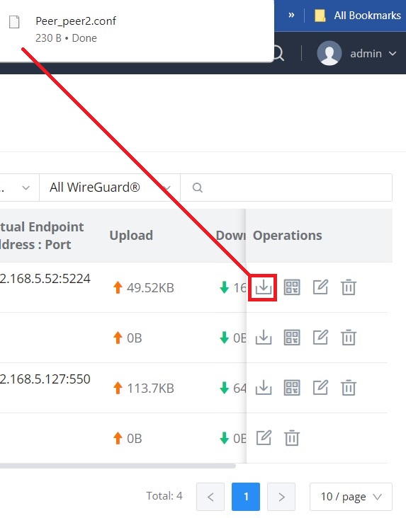
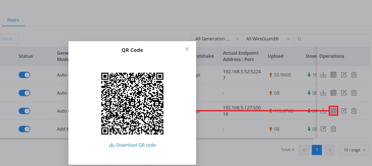
- Download client configuration file or QR code.
- Edit or delete the client configuration
To view connected clients, navigate to VPN → WireGuard® → Remote Clients.

The user can download the config file after adding the client.
Or scanning the QR code for devices with camera support.
IPSec
IPSec, or Internet Protocol Security, is mainly used to authenticate and encrypt packets of data sent over the network layer. To accomplish this, they use two security protocols – ESP (Encapsulation Security Payload) and AH (Authentication Header); the former provides both authentication and encryption, whereas the latter provides only authentication for the data packets. Since both authentication and encryption are equally desirable, most of the implementations use ESP.
IPSec supports two different encryption modes; they are Tunnel (default) and Transport mode. Tunnel mode is used to encrypt both payloads as well as the header of an IP packet, which is considered to be more secure. Transport mode is used to encrypt only the payload of an IP packet, which is generally used in gateway or host implementations.
IPSec also involves the IKE (Internet Key Exchange) protocol, which is used to set up the Security Associations (SA). A Security Association establishes a set of shared security parameters between two network entities to provide secure network layer communication. These security parameters may include the cryptographic algorithm and mode, traffic encryption key, and parameters for the network data to be sent over the connection. Currently, there are two IKE versions available – IKEv1 and IKEv2. IKE works in two phases:
Phase 1: ISAKMP operations will be performed after a secure channel is established between two network entities.
Phase 2: Security Associations will be negotiated between two network entities.
IKE operates in three modes for exchanging keying information and establishing security associations – Main, Aggressive, and Quick mode.
• Main Mode: is used to establish phase 1 during the key exchange. It uses three two-way exchanges between the initiator and the receiver. In the first exchange, algorithms and hashes are exchanged. In the second exchange, shared keys are generated using the Diffie-Hellman exchange. In the last exchange, verification of each other’s identities takes place.
• Aggressive mode: provides the same service as the main mode, but it uses two exchanges instead of three. It does not provide identity protection, which makes it vulnerable to hackers. The main mode is more secure than this.
• Quick mode: After establishing a secure channel using either the main mode or aggressive mode, the quick mode can be used to negotiate general IPsec security services and generate newly keyed material. They are always encrypted under a secure channel and use a hash payload that is used to authenticate the rest of the packet.
IPSec Site-to-Site
To build an IPSec secure tunnel between two sites located in two distant geographical locations, we can use the sample scenario below:
The branch office router needs to connect to the Headquarters office via an IPSec tunnel; on each side, we have a GCC device. Users can configure the two devices as follows:
The branch office router runs a LAN subnet 192.168.1.0/24, and the HQ router runs a LAN subnet 192.168.3.0. The public IP of the branch office router is 1.1.1.1, and the IP of the HQ router is 2.2.2.2.
Go to VPN → IPSec → Site-to-Site, then click the button to add a VPN Client.
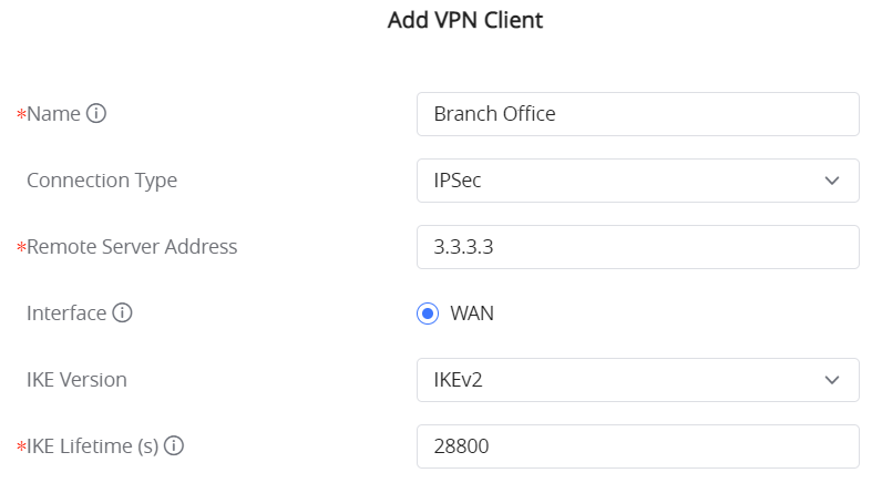
○ Phase 1
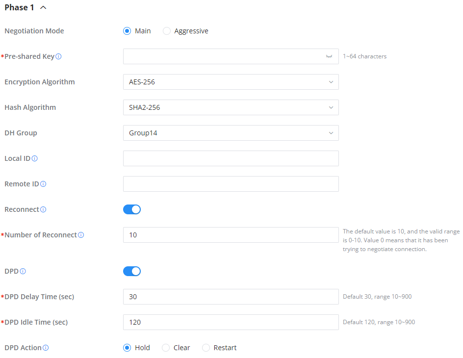
○ Phase 2
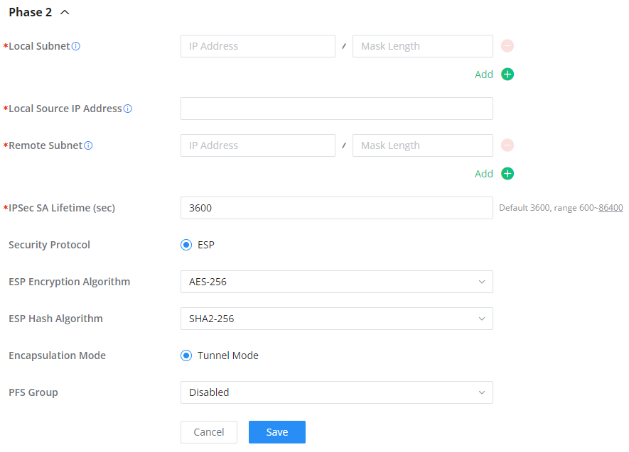
After this is done, press “Save” and do the same for the HQ Router. The two routers will build the tunnel and the necessary routing information to route traffic through the tunnel back and from the branch office to the HQ network.
- Create the remote user credentials:
To create the remote user account, which will be required to be entered on the client side and authenticated on the server side, please refer to the Remote Users section.
IPSec Client-to-Site
Go under VPN → IPSec → Client-to-Site, then fill in the following information:
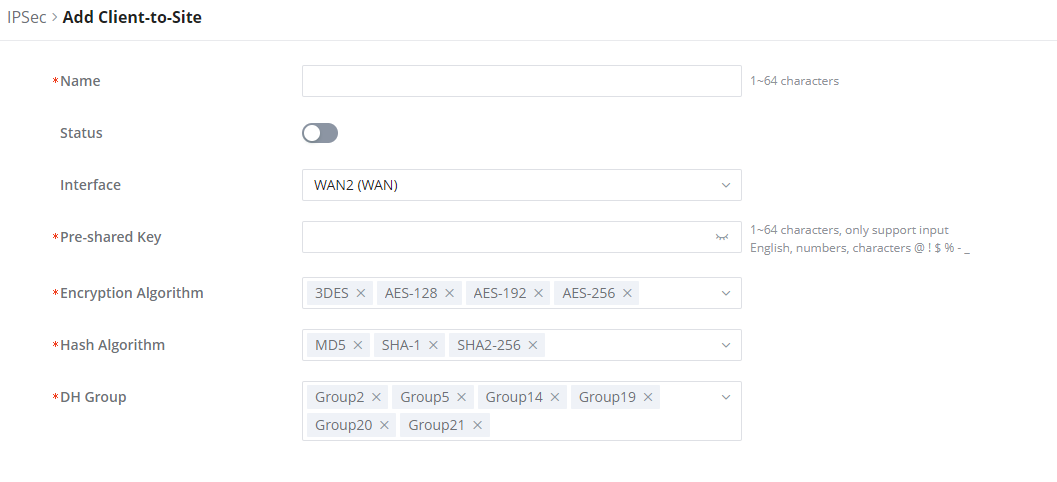
OpenVPN®
OpenVPN®is a virtual private network solution that establishes a secure connection to a distant host. VPN provides the possibility to reach hosts that are located on a local area network and be logically located in that same local area network, hence the name Virtual Private Network. The connection between the client and the server is authenticated using a username and password and/or TLS encryption.
Typically, users can set up a client-to-server connection, the client being a computer, and the server being a GWN router or a GCC device. The user can also set up a site-to-site VPN connection using OpenVPN® to interconnect two sites securely. In the following sections, you can find an explanation for all the configuration fields for OpenVPN®.
OpenVPN® Client
There are two ways to use the device as an OpenVPN® client:
1. Upload the client certificate created from an OpenVPN® server to the GCC6000 device.
2. Create client/server certificates on the GCC6000 device and upload the server certificate to the OpenVPN® server.
Go to Go to VPN → OpenVPN® → OpenVPN® Clients and follow the steps below:
Click on the button. The following window will pop up.
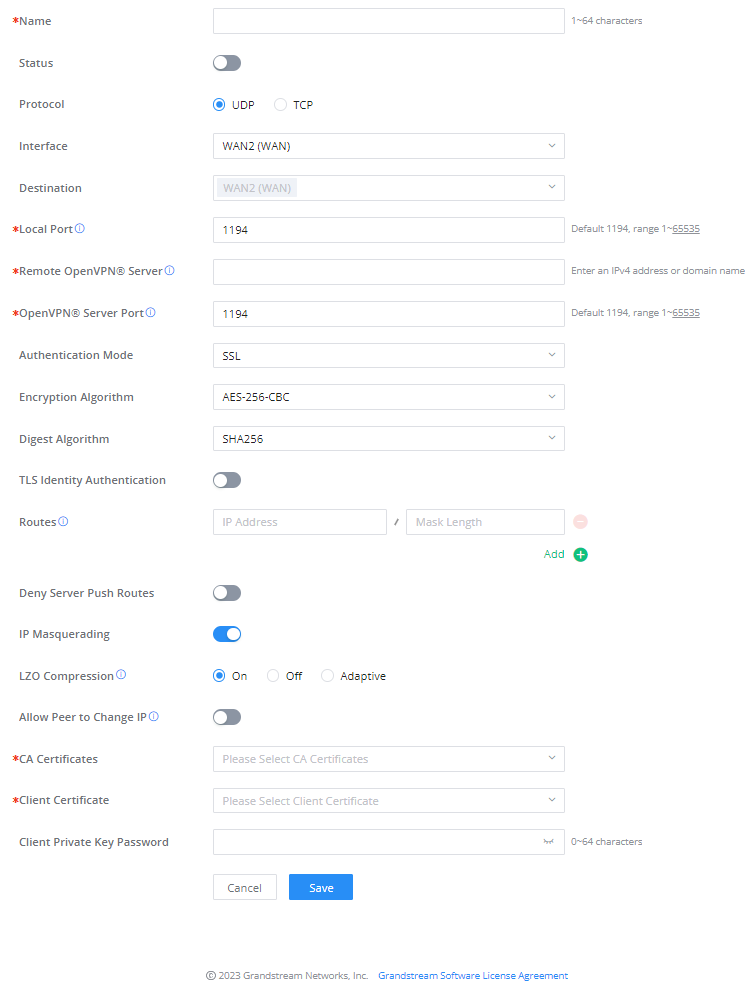
Click after completing all the fields.
Name | Enter a name for the OpenVPN® Client. |
Status | Toggle on/off the client account. |
Protocol | Specify the transport protocol used.
Note: The default protocol is UDP. |
Interface | Select the WAN port to be used by the OpenVPN® client. |
Destination | Select the WANs, VLANs and VPNs (clients) destinations that will be used by this OpenVPN® client. |
Local Port | Configures the client port for OpenVPN®.The port between the OpenVPN® client and the client or between the client and the server should not be the same. |
Remote OpenVPN® Server | Configures the remote OpenVPN® server. Both IP address and domain name are supported. |
OpenVPN® Server Port | Configures the remote OpenVPN® server port |
Authentication Mode | Choose the authentication mode.
|
Encryption Algorithm | Choose the encryption algorithm. The encryption algorithms supported are:
|
Digest Algorithm | Select the digest algorithm. The digest algorithms supported are:
|
TLS Identity Authentication | Enable TLS identity authentication direction. |
TLS Identity Authentication Direction | Select the indentity authentication direction.
|
TLS Pre-Shared Key | Enter the TLS pre-shared key. |
Routes | Configures IP address and subnet mask of routes, e.g., 10.10.1.0/24. |
Deny Server Push Routes | If enabled, client will ignore routes pushed by the server. |
IP Masquerading | This feature is a form of network address translation (NAT) which allows internal computers with no known address outside their network, to communicate to the outside. It allows one machine to act on behalf of other machines. |
LZO Compression | Select whether to activate LZO compression or no, if set to “Adaptive”, the server will make the decision whether this option will be enabled or no. |
Allow Peer to Change IP | Allow remote change the IP and/or Port, often applicable to the situation when the remote IP address changes frequently. |
CA Certificates | Click on “Upload” and select the CA certificate |
Client Certificate | Click on “Upload” and select the Client Certificate. |
Client Private Key Password | Enter the client private key password. |
OpenVPN® Client
OpenVPN® Server
To use the GCC6000 as an OpenVPN® server, you will need to start creating OpenVPN® certificates and remote users.
To create a new VPN server, navigate to Web UI → VPN → OpenVPN® page → OpenVPN® Servers tab.
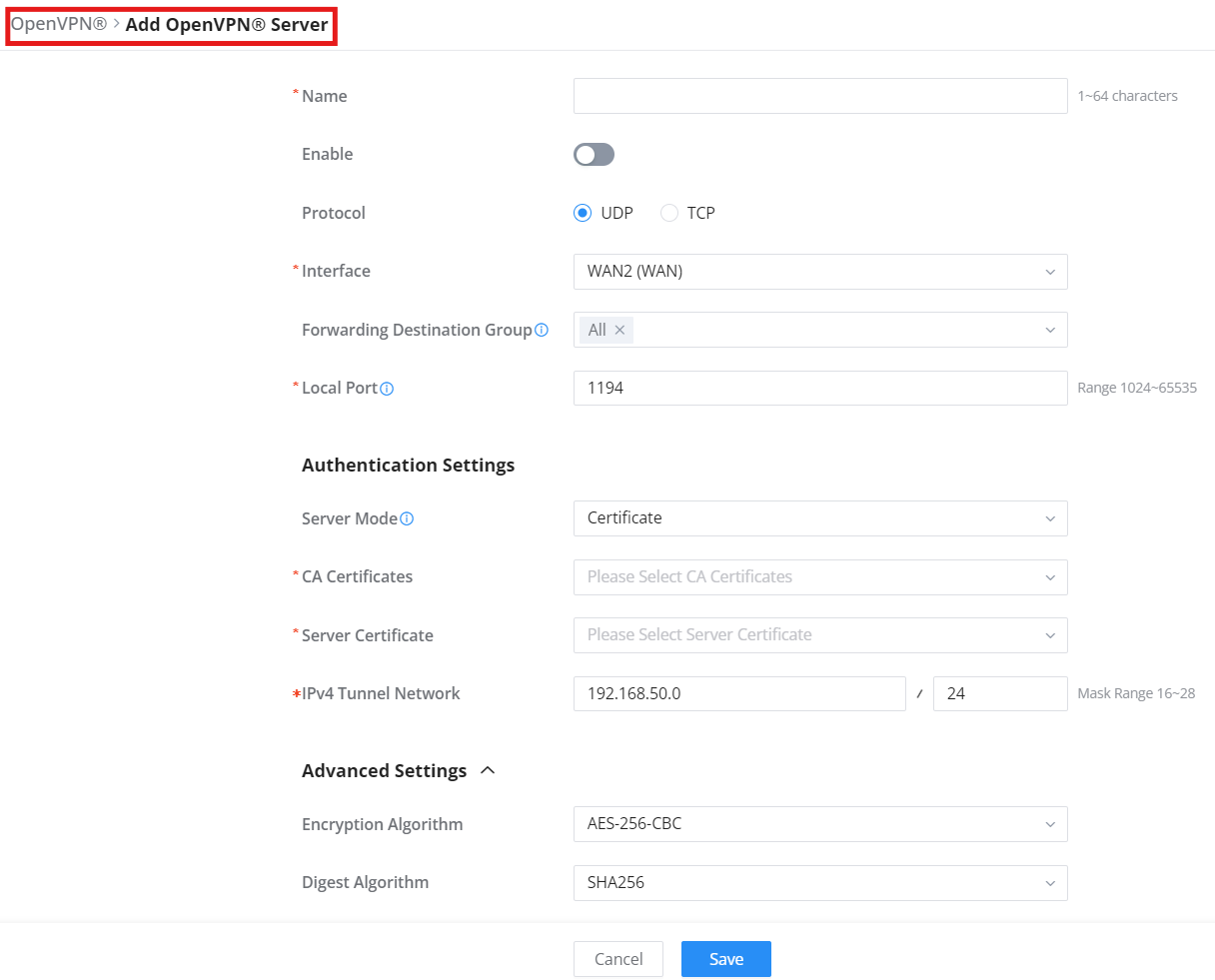
Clickafter completing all the fields.
Refer to the table below:
Name | Enter a name for the OpenVPN® server. |
Status | Toggle ON or OFF to enable or disable the OpenVPN® Server. |
Protocol | Choose the Transport protocol from the dropdown list, either TCP or UDP. The default protocol is UDP. |
Interface | Select from the drop-down list the exact interface (WAN). |
Destination | Select from the drop-down list the destination (WAN or VLAN). |
Local Port | Configure the listening port for OpenVPN® server. The default value is 1194. |
Server Mode | Select the authentication method used between the server and connected clients. support for RADIUS-based authentication modes. Available options: Certificate: Only certificates are used (no username/password). User Authentication: Username and password only. Certificate + User: Requires both certificate and user login. RADIUS Authentication: Uses external RADIUS server for authentication. Certificate Authentication + RADIUS Authentication: Dual validation with both certificate and RADIUS. PSK: Uses a pre-shared key for IP-based tunneling. Notes: • If the Server Mode is set to Certificate, User Authentication, Certificate + User, or PSK, go to Remote Users to configure the corresponding user settings. • If the OpenVPN® Server uses RADIUS Authentication, all clients connecting to the VPN must use User Authentication. |
Encryption Algorithm | Choose the encryption algorithm from the dropdown list to encrypt data so that the receiver can decrypt it using same algorithm. |
Digest Algorithm | Choose digest algorithm from the dropdown list, which will uniquely identify the data to provide data integrity and ensure that the receiver has an unmodified data from the one sent by the original host. |
TLS Identicy Authentication | This option uses a static Pre-Shared Key (PSK) that must be generated in advance and shared among all peers. This feature adds extra protection to the TLS channel by requiring that incoming packets have a valid signature generated using the PSK key. |
TLS Identity Authentication Direction | Select from the drop-down list the direction of TLS Identity Authentication, three options are available (Server, Client or Both). |
TLS Pre-Shared Key | If TLS Identicy Authentication is enabled, enter the TLS Pre-Shared Key. |
Allow Duplicate Client Certificates | Click on “ON” to allow duplicate Client Certificates |
Redirect Gateway | When redirect-gateway is used, OpenVPN® clients will route DNS queries through the VPN, and the VPN server will need to handle them. |
Push Routes | Specify route(s) to be pushed to all clients. Example: 10.0.0.1/8 |
LZO Compression Algorithm | Select whether to activate LZO compression or no, if set to “Adaptive”, the server will make the decision whether this option will be enabled or no. |
Allow Peer to Change IP | Allow remote change the IP and/or Port, often applicable to the situation when the remote IP address changes frequently. |
CA Certificate | Select a generated CA from the dropdown list or add one. |
Server Certificate | Select a generated Server Certificate from the dropdown list or add one. |
IPv4 Tunnel Network/Mask Length | Enter the network range that the GWN70xx will be serving from to the OpenVPN® client. Note: The network format should be the following 10.0.10.0/16. The mask should be at least 16 bits. |
Create OpenVPN® Server
- Create the remote user credentials:
To create the remote user account, which will be required to be entered on the client side and authenticated on the server side, please refer to the Remote Users section.
ZeroTier
ZeroTier is a secure, peer-to-peer virtual networking solution that allows devices in different physical locations to appear on the same local network. It simplifies remote access and interconnectivity across NATs and firewalls — without requiring port forwarding or static IPs.
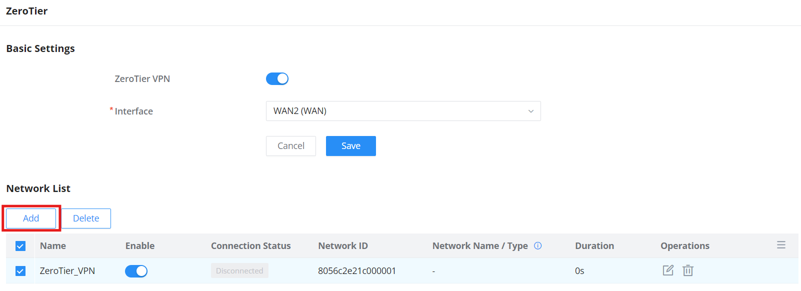
Navigate to: VPN → ZeroTier
Basic Settings – ZeroTier
- ZeroTier VPN: Toggle to enable/disable the service
- Interface: Choose the WAN interface to bind the ZeroTier tunnel (e.g., WAN1, WAN2)
Add a Network
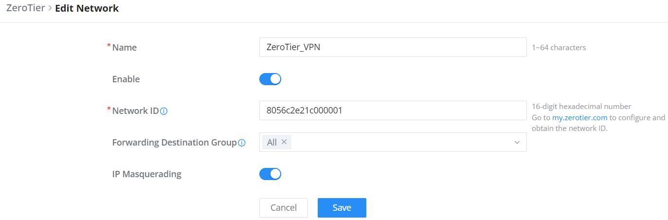
Click Add to create a new virtual network entry.
| Field | Description |
|---|---|
| Name | Custom network name (1–64 characters) |
| Network ID | 16-digit hexadecimal ZeroTier network ID (created via my.zerotier.com) |
| Forwarding Destination Group | Select which routing group to forward traffic to |
| IP Masquerading | Enable to allow NAT for this virtual network |
Best Practice
For best results:
- Enable IP Masquerading when accessing internet-bound devices
- Only enable known and secure network IDs
- Refer to your ZeroTier Central account for full network creation, member control, and routing rules
For step-by-step instructions, real-world use cases, and best practices on setting up ZeroTier across supported GCC60xx devices, please refer to the official configuration guide: ZeroTier Configuration Guide
PPTP
A data-link layer protocol for wide-area networks (WANs) based on the Point-to-Point Protocol (PPP) and developed by Microsoft, enables network traffic to be encapsulated and routed over an unsecured public network such as the Internet. Point-to-Point Tunneling Protocol (PPTP) allows the creation of virtual private networks (VPNs), which tunnel TCP/IP traffic through the Internet.
PPTP Clients
To configure the PPTP client on the GCC6000, navigate to VPN → PPTP → PPTP Clients and set the following:
1. Click on the “Add” button.
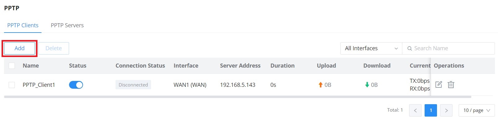
The following window will pop up.
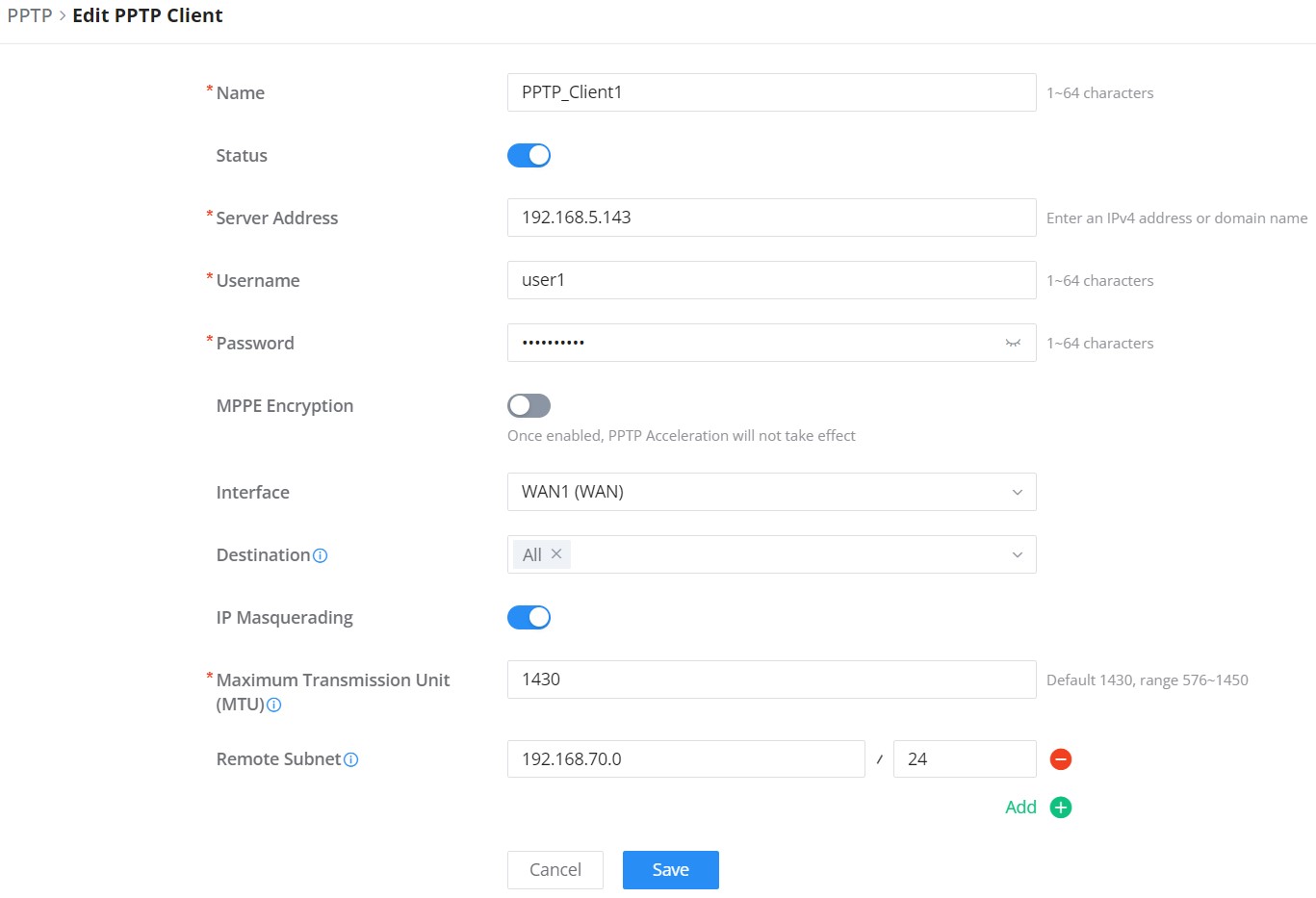
Name | Enter a name for the PPTP client. |
Status | Toggle on/off the VPN client account. |
Server Address | Enter the IP/Domain of the remote PPTP Server. |
Username | Enter the Username for authentication with the VPN Server. |
Password | Enter the Password for authentication with the VPN Server. |
Interface | Choose the interfaces. Note: Set forwarding rules in firewall automatically to allow traffic forwarded from VPN to the selected WAN port. If remote device is allowed to access, please set the corresponding forwarding rules in firewall. |
Forwarding Destination Group | Choose to which destination group or WAN to allow traffic from the VPN, this will generate automatically a forwarding rule under the menu Firewall → Traffic Rules → Forward. |
Remote Subnet | Configures the remote subnet for the VPN. The format should be “IP/Mask” where IP could be either IPv4 or IPv6 and mask is a number between 1 and 32. example: 192.168.5.0/24 |
MPPE Encryption | Enable / disable the MPPE for data encryption. By default, it’s disabled. |
IP Masquerading | This feature is a form of network address translation (NAT) which allows internal computers with no known address outside their network, to communicate to the outside. It allows one machine to act on behalf of other machines. |
Maximum Transmission Unit (MTU) | This indicates the size of the packets sent by the router. Please do not change this value unless necessary. |
PPTP Client Configuration
PPTP Servers
To add a PPTP Server, please navigate to Web UI → VPN → PPTP page → PPTP Servers tab, then click on the “Add” button.
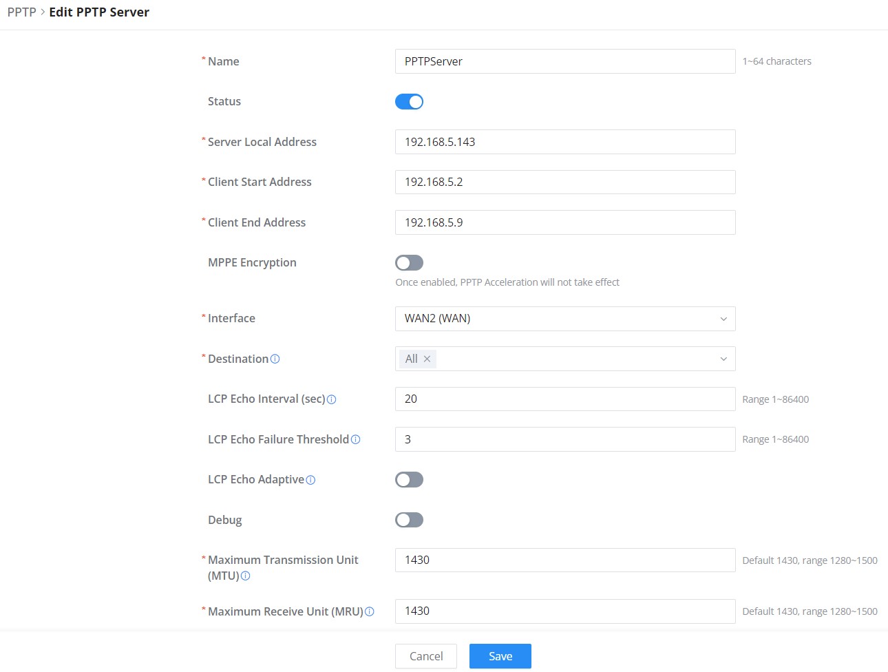
Name | Enter a name for the PPTP Server. |
Enable | Toggle ON or OFF to enable or disable the PPTP Server VPN. |
Client Address Type | Used to select the IP address source method for PPTP clients after they connect.
|
Local Subnet | Select the local subnet for the VPN clients. |
Server Local Address | Specify the server local address |
Client Start Address | specify client start IP address |
Client End Address | specify client end IP address |
Interface | Select from the drop-down list the exact interface (WAN port). |
Forwarding Destination Group | Select the Destination from the drop-down list (WAN or VLAN). Note: When selecting “All”, subsequent new interfaces will be automatically included. |
MPPE Encryption | Enable / disable the MPPE for data encryption. By default, it’s disabled. |
LCP Echo Interval (sec) | Configures the LCP echo send interval. |
LCP Echo Failure Threshold | Set the maximum number of Echo transfers. If it is not answered within the set request frames, the PPTP server will consider that the peer is disconnected and the connection will be terminated. |
LCP Echo Adaptive |
|
Debug | Toggle On/Off to enable or disable debug. |
Maximum Transmission Unit (MTU) | This indicates the size of the packets sent by the router. Please do not change this value unless necessary. By default is 1430. |
Maximum Receive Unit (MRU) | MRU indicates the size of the received packets. By default is 1430. |
Preferred DNS Server | specify the preferred DNS server. Ex: 8.8.8.8 |
Alternative DNS Server | specify the alternative DNS server. Ex: 1.1.1.1 |
PPTP Server
- Create the remote user credentials:
To create the remote user account, which will be required to be entered on the client side and authenticated on the server side, please refer to the Remote Users section.
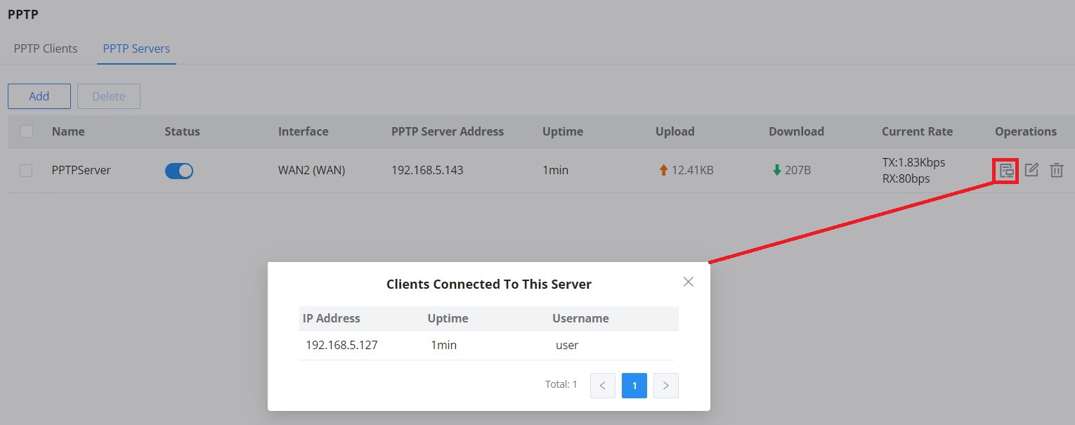
To view the clients connected to this server, click on the “Client List” icon as shown below:
L2TP
The L2TP Client allows secure tunneling to a remote L2TP server. This interface includes support for IPSec Encryption, offering enhanced security and configurable Phase 1/Phase 2 parameters.
To configure the L2TP client on the GCC6000 device, navigate under “VPN → VPN Clients” and set the following:
1. Click on the “Add” button, and the following window will pop up.


Field | Description |
Name | Set a name for the L2TP connection (1–64 characters). |
Enable | Toggle to activate or deactivate the L2TP client. |
Interface | Select the WAN interface used for the connection. |
Forwarding Destination Group | Choose a group to forward traffic to after tunnel connection. |
Server Address | Enter the domain or IP address of the remote L2TP server. |
Username | Provide the username for L2TP authentication. |
Password | Enter the L2TP authentication password. |
IPSec Encryption | Enable to encrypt traffic over the L2TP tunnel using IPSec. Automatically adjusts MTU to 1300. |
Pre-shared Key | Required if IPSec is enabled. Must match the key configured on the L2TP server. |
Remote Subnet | Specify the subnet (IP/mask) on the remote network. |
Advanced Settings | |
IP Masquerading | Enable NAT for outbound traffic from the VPN tunnel. |
Maximum Transmission Unit (MTU) | Set the MTU size (Range: 576–1300 when IPSec is enabled). |
IKE Version | Choose IKEv1 or IKEv2 for key negotiation. |
Negotiation Mode | Select ‘Main’ or ‘Aggressive’ mode for Phase 1. |
Encryption Algorithm | Set preferred encryption methods for Phase 1. |
Hash Algorithm | Choose hashing algorithms for Phase 1. |
DH Group | Define the Diffie-Hellman group(s) for key exchange. |
Local ID | Optional: Enter an identifier for the local endpoint. |
Remote ID | Optional: Enter the identifier for the remote endpoint. |
Security Protocol | Set to ESP (Encapsulating Security Payload) for data encryption. |
ESP Encryption Algorithm | Select encryption algorithms for Phase 2. |
ESP Hash Algorithm | Set hashing methods for Phase 2. |
Encapsulation Mode | Choose between Tunnel or Transport mode. |
PFS Group | Enable and set Perfect Forward Secrecy (optional). |
L2TP Client Configuration
Click “Save” after completing all the fields.

Remote Users
To create the VPN user accounts, please navigate to VPN → Remote Users, then click “Add”. The account configured will be used for the client to authenticate to the VPN server. The remote client user that can be created in this section is for PPTP, IPSec, and OpenVPN.

If the remote user is using OpenVPN®, the configuration file can be exported as an .ovpn file. This file can then be modified as needed to fit the user’s requirements.
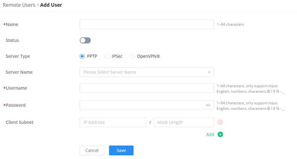
Name | Enter a name for the user. This name will not be used to log in. |
Status | Enable or disable this account. |
Server Type | Choose the type of the server.
|
Server Name | Enter the server’s name. |
Username | Enter the username. This username will be used to log in. |
Password | Enter the password. |
Client Subnet | Specify the client subnet. |
Add VPN Remote Users
To authenticate a remote user into the VPN server successfully, the username and password are used alongside the client certificate. To create a client certificate, please refer to the Certificates section.
To configure the VPN clients for each VPN server type, please refer to the respective VPN client configuration above.
ROUTING
Routing Table
The Routing Table page displays the routes currently configured on your Grandstream device. It shows key information such as the IP address, protocol type, outgoing interface, next hop, and administrative distance for each route.
You can toggle between IPv4 Routing Table and IPv6 Routing Table using the tabs at the top of the page. Additionally, you can filter routes based on outgoing interfaces or search for a specific next hop.
- IP Address: The destination network or IP address.
- Protocol Type: Indicates the type of routing (e.g., Direct, Static, VPN).
- Outgoing Interface: The network interface used for routing traffic to the destination.
- Next Hop: The IP address of the next device in the routing path.
- Administrative Distance: The trustworthiness of the route.
To view the routing table, navigate to Routing → Routing Table.

Policy Routes
In this section, the user can create a policy route to either load balance or backup (Failover) between 2 or more WAN ports. This feature allows a network administrator to make advanced routing decisions for traffic passing through the router and for high granularity control over policies that dictate what WAN port and even VLAN traffic should use. Traffic controlled this way can be balanced across multiple VLANs.
Load Balance Pool
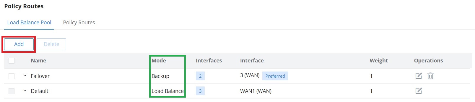
To create a load balance rule, navigate to the Routing → Policy Routes page → Load Balance Pool tab, click on the “Add” button, then select the mode (Load Balance or Backup). After selecting the WAN ports from the drop-down list, specify the load balancing strategy to use; the available options are:
- Connection-Based: Traffic will be distributed evenly among the links and will rely on the weight values only to define the priority.
- Source IP address: Traffic will be distributed to the links based on the source IP address. Traffic from the same IP address will be routed through the same interface, reducing potential network issues.
- Source & Destination IP Addresses: Traffic will be distributed to links based on the source IP address and destination IP address. Traffic with the same source IP address and destination IP address will be routed through the same interface.
In addition, specify the weight for each port added; the weight determines the priority for each interface, and the higher the weight, the higher the priority.
Please refer to the figures below:


Policy Route
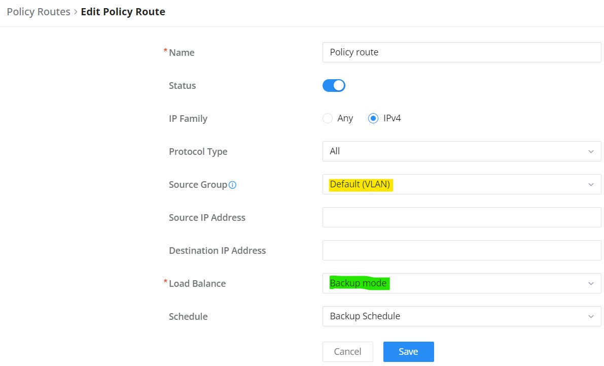
On the second tab (Policy Routes), the user can specify which Networks (VLANs) can use which Load Balance rule (must be created first). Also, the user can specify the protocol type, source, and destination IP and even assign a schedule for it.
To create a Policy Route, please navigate to the Routing → Policy Routes page → Policy Routes tab, then click on the “Add” button as shown below:

Static Routes
Static routing is a form of routing by manually configuring the routing entries, rather than using dynamic routing traffic for any service that requires a static address that never changes.
GCC601X(W) supports setting IPv4 or IPv6 Static Routes, which can be accessed from GCC601X(W)WebGUI Routing → Static Routing.
To add a new Static Route, the user needs to click .
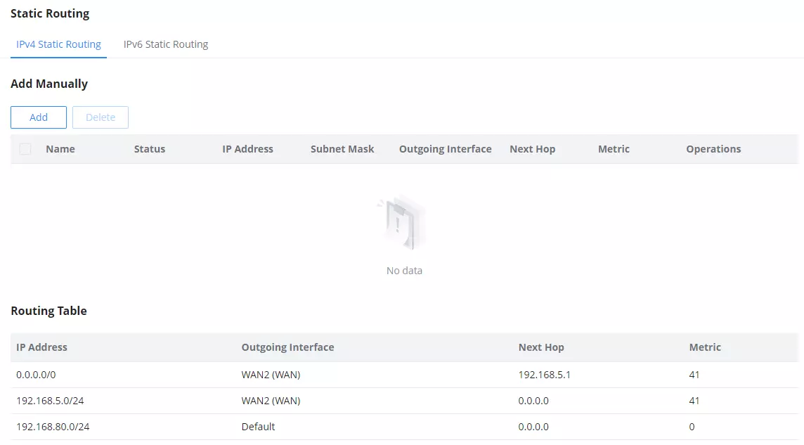
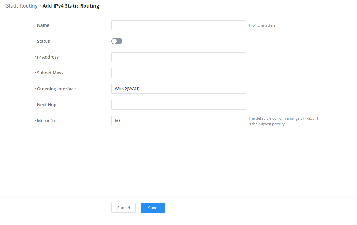
Name | Specify a name for the Static Routing |
Status | enable or disable the Static Routing |
IP Address | Specify the IP address |
Subnet Mask | Enter the Subnet Mask |
Outgoing Interface | Select the ougoing interface (WAN, VLAN or Blackhole). Note: Blackhole used to direct traffic destined for specific locations to a blackhole (i.e., a virtual drop point), where the traffic will be discarded instead of being forwarded to any destination. |
Next Hop | Specify the next Hop |
Metric | When there are multiple routings in the network that can reach the same destination, the priority of routing rules can be adjusted by setting metric, and the packets will be forwarded according to the path with the smallest metric. |
Add IPv4 Static Routing
Open Shortest Path First (OSPF)
Open Shortest Path First (OSPF) is a dynamic routing protocol used in IP networks to determine the best path for data packets across the network. In Grandstream GCC6000 devices, OSPF allows for efficient routing across large and complex networks by exchanging routing information between routers, ensuring each router knows the most optimal path to various network destinations.
The GCC6000 device supports a robust OSPF configuration to provide flexibility, security, and scalability for enterprise-level networks. OSPF is designed to work within an Autonomous System (AS), ensuring fast convergence and optimal routing decisions based on link state information.
To view or configure OSPF settings, navigate to Routing → OSPF.
Global Settings
The Global Settings tab contains important configurations to enable and fine-tune OSPF on your Grandstream GCC6000 device. Some of the key options on this page include:
- Router ID: This field defines a unique IPv4 address that identifies your router within the OSPF network. It must be set for the router to participate in OSPF.
- Always Advertise Default Route: This toggle ensures that the router always advertises the default route (0.0.0.0/0) to other routers in the OSPF network, designating it as a gateway.
- Metric: The metric determines the cost of a route in OSPF. Lower values indicate a more preferred route, guiding the OSPF protocol in route selection.
- Metric Type: You can choose between:
- Type 1: Considers both the OSPF metric and other route costs.
- Type 2: Considers only the OSPF metric, typically used for external routes.
- External Route Import: This section allows you to import routes from other routing protocols such as Direct, Static, RIP, and BGP, giving you flexibility when integrating with different network setups.

Interface Settings
In this section, users can view, add, or modify OSPF configurations for each interface on the device. The interface settings allow fine-tuning of OSPF behavior by defining key parameters like intervals for OSPF hello packets, authentication types, and the cost metric for each interface.
To navigate: Routing → OSPF → Interface Settings

To add a new OSPF interface, they can click on the Add button. To edit an existing interface, click on the Edit icon next to the interface. Refer to the images for a visual guide.

Key Configurations:
- Name: A customizable label for the interface.
- Enable: Toggle to enable or disable OSPF for this interface.
- Interface: Select the specific interface (e.g., VLAN) where OSPF should run.
- Area ID: Identifies the OSPF area the interface belongs to (default:
0.0.0.0for backbone). - Hello Interval (Sec): The interval between OSPF Hello packets to maintain neighbor relationships (default: 10 seconds).
- Dead Interval (Sec): The interval after which a neighbor is considered down if no Hello packet is received (default: 40 seconds).
- Cost: Determines the OSPF route cost; lower values are preferred.
- Priority: Controls the interface’s eligibility to become the Designated Router (DR).
- Authentication Type: Choose between No Authentication, Simple Password, or MD5 Authentication for OSPF packets.
These configurations help ensure optimal routing behavior and secure communication between OSPF-enabled devices.
Area Settings
The OSPF Area Settings tab allows users to configure OSPF areas to optimize routing and control traffic within different network zones. This section is essential for network segmentation and ensuring efficient routing within the Open Shortest Path First (OSPF) protocol in the GCC6000 device. OSPF divides networks into multiple areas to decrease routing overhead and enhance scalability.
To navigate to this page, go to Routing → OSPF → Area Settings.
To Add or Edit an Area:
- Click the Add button to create a new area.
- Click the Edit icon next to an existing area to modify its configuration.

Key Configurations in Area Settings:
- Area ID: A unique identifier for the OSPF area, defined in IPv4 format or an integer.
- Area Type: Options include:
- None: No special designation for the area.
- Stub: Restricts external route advertisements to minimize routing overhead.
- NSSA (Not-So-Stubby Area): Balances between a stub and full OSPF area by allowing specific external routes.
- No Summary: Prevents summarized routes from being sent into the area, promoting more specific routing information.
- Conversion Type: Manages area type conversions:
- Never: Disables conversion.
- Always: Enables automatic conversion.

Neighbor Info
The Neighbor Info tab provides a summary of neighboring OSPF routers that have formed adjacencies with your Grandstream GCC6000 device. This feature helps monitor OSPF neighbor relationships and troubleshoot connectivity between routers in a network running OSPF.
To view this information, navigate to Routing → OSPF → Neighbor Info.
Key Parameters Displayed in Neighbor Info:
- Neighbor ID: The unique identifier of the neighboring router.
- Priority: Indicates the priority value of the neighbor, which helps in determining the designated router (DR) and backup designated router (BDR).
- Status: Shows the current state of the OSPF neighbor (e.g., Full, Init, 2-Way).
- Dead Time: The countdown before the neighbor is considered down, based on the Hello interval.
- Neighbor Address: The IP address of the neighbor.
- Interface: The interface on your router that is communicating with the neighbor.
- Uptime: The amount of time the OSPF neighbor relationship has been established.
This tab helps monitor OSPF relationships in real-time and identify potential routing issues.

RIP
Routing Information Protocol (RIP) is a distance-vector routing protocol used by routers to exchange routing information within a local network or across networks. In the GCC6000 device, RIP allows the configuration of both RIP Version 1 (RIPv1) and RIP Version 2 (RIPv2) to determine how routers communicate route information, maintain updated routing tables, and ensure efficient network management.
The RIP section is divided into four main tabs:
- Global Settings
- Interface Settings
- Route Advertisement
- Neighbor Info
Each tab provides specific configurations for setting up and managing RIP routing on your network.
RIP – Global Settings
The Global Settings tab is where the general RIP configuration is defined. You can enable RIP, choose the RIP version, and configure important parameters such as RIP Distance, Timers, and External Route Import options.
To navigate to this section: Go to Routing → RIP → Global Settings.
- RIP: Toggle to enable or disable RIP on the GCC6000 device.
- RIP Version:
- RIPv1: Basic, classful routing protocol, no subnet information.
- RIPv2: Classless routing protocol with subnet and route tags support.
- RIP Distance: Specifies the administrative distance for RIP routes, which helps in determining the reliability of the route (default is 120).
- Always Advertise Default Route: When enabled, the router will always advertise a default route to other routers.
Timer Configuration:
- Update Timer: The interval (in seconds) between route update messages.
- Invalid Timer: The duration (in seconds) after which a route is considered invalid if no update has been received.
- Garbage Collection Timer: The time after which an invalid route is removed from the routing table.
External Route Import:
You can configure the router to import external routes from the following sources:
- Direct Routes
- Static Routes
- OSPF Routes
- BGP Routes
For each protocol type, you can configure the metric values that affect the priority of the route.

RIP – Interface Settings
The RIP Interface Settings tab allows users to configure RIP interfaces on the GCC6000 device. It displays a list of interfaces that can participate in the RIP routing protocol. Users can manage settings like the RIP version used for transmitting and receiving, authentication types, and other advanced options for RIP routing.
To add an interface, click the Add button, or to edit an interface, click the edit icon. See the provided images for visual guidance.

Key Parameters:
- Interface: Specifies the interface that RIP will run on (e.g., VLAN, physical interface).
- RIP Tx Version / RIP Rx Version: Select the RIP version for transmitting and receiving routes.
- RIPv2 Broadcast: Enable/disable broadcasting RIP version 2 messages.
- Interface Suppression: Suppresses sending RIP updates on the interface.
- Loop Protection: Protects from routing loops using the Split Horizon method.
- Authentication Type: Choose the type of authentication for RIP (e.g., MD5).
- Secret: Authentication key (password) for MD5 or simple authentication.

RIP – Route Advertisement
The Route Advertisement tab in the RIP section allows users to define specific routes that need to be advertised to other routers in the network. This is essential for controlling which sub-networks are shared across the RIP protocol. Proper route advertisement ensures efficient routing and network management by determining what parts of the network can be reached through the RIP-enabled router.
Navigation: To view or modify Route Advertisement settings, navigate to Routing → RIP → Route Advertisement.

Key Features in the Route Advertisement Tab:
- Subnet Address / Mask Length: Displays the list of subnets being advertised along with their corresponding subnet mask lengths.
- Add Route Advertisement: This feature allows users to add one or more subnets to advertise across the network. When adding, users need to provide both the Subnet Address and the Mask Length (e.g.,
/24for Class C networks). - Operations: Each route entry has options to edit or delete the advertisement.
If the user wishes to add a new route advertisement, they can click on the Add button and provide the required subnet address and mask length. Once configured, these routes will be shared across the network via RIP.

RIP – Neighbor Info
The Neighbor Info tab in the RIP configuration provides details about the neighboring RIP routers that communicate with the router to exchange routing information. This tab displays crucial information regarding the neighbors, which helps in managing and troubleshooting RIP routing within the network.
Navigation: To view RIP neighbor details, navigate to Routing → RIP → Neighbor Info.
Key Information Displayed:
- Interface: The network interface that is communicating with the neighbor router.
- RIP Version Info: Displays the version of RIP used by the neighbor router.
- Default Distance: Indicates the default administrative distance for the neighbor.
- Neighbor Address: The IP address of the neighboring RIP router.
- Update Time: The last time an update was received from the neighboring router.

Border Gateway Protocol (BGP)
The Border Gateway Protocol (BGP) is a key exterior gateway routing protocol used to exchange routing information between different autonomous systems (AS) over the internet. BGP plays a critical role in determining the best path for data packets as they travel across various networks. On Grandstream GCC6000 device, BGP is configured under the Routing section, offering a powerful solution for network administrators to control traffic between different AS networks.
To configure BGP on Grandstream routers, navigate to Routing → BGP.
BGP – Global Settings
The Global Settings tab in BGP configuration allows the user to define the general BGP parameters essential for the protocol’s operation.
Key Parameters:
- AS (Autonomous System): The AS number identifies the autonomous system to which the router belongs. It is a required value with a valid range from 1 to 4,294,967,295.
- Router ID: A unique identifier in IPv4 format for the router. The router ID is required and helps identify this router in the BGP network.
External Route Import:
- This section allows users to configure which route types (Direct, Static, OSPF, and RIP) can be imported into the BGP routing table.
- Protocol Type: You can check the boxes for the route types to import, and set their respective route metrics, which determine the preference for routes. Lower metric values have higher preference.

BGP – Peer
In the BGP (Border Gateway Protocol) Peer tab, users can view, add, or edit BGP peers that are configured on the router. A BGP peer is a neighboring router with which routing information is exchanged. Peers are established through their IP address and ASN (Autonomous System Number).
To add or modify a BGP peer:
- Click on the Add button to create a new peer.
- To modify an existing peer, click the Edit icon next to the peer you want to change.

Key configurable fields in this tab include:
- Remote AS: The Autonomous System Number of the remote peer.
- Remote Address: The IP address of the remote BGP peer.
- Connection Hold Time: The maximum amount of time to hold a BGP connection without receiving a keepalive message.
- Connect Retry Time: The interval to retry establishing a BGP connection.
- Keepalive Time: The frequency of sending keepalive messages to ensure the peer is active.
- MD5 Authentication: Optional security for BGP connections using an MD5 password for session authentication.

BGP – Route Advertisement
The Route Advertisement tab allows users to manage BGP-advertised routes by adding or removing specific subnets. Here, you can define which networks are advertised to BGP peers.

To add or modify an advertised route, click Add or the Edit icon. The configuration will prompt you to enter the subnet address and mask length, then click Save.
Key configurable fields in this tab include:
Subnet Address / Mask Length: Specify the network’s IP address and the corresponding subnet mask length (e.g., 10.0.0.0 / 24).

BGP – Peer Info
The Peer Info tab in the BGP section provides details on the active BGP peers. Here, users can monitor the status and connection of their BGP peers to ensure proper route exchange.
- BGP Version Info: Shows the BGP protocol version in use, typically version 4.
- Peer Address: Displays the IP address of the BGP peer.
- Peer AS: Shows the Autonomous System (AS) number of the peer.
- Status:
- Established: Indicates a fully functional BGP connection where routes are being successfully exchanged between peers. This state confirms that the BGP connection is active and stable.
- Active: Shows the BGP connection is active but may not have fully exchanged routes.
- Uptime: Tracks how long the peer connection has been established and active.
You can click the Refresh button to update the status of the peers. This allows users to quickly verify if their BGP peers are properly connected and whether routes are being exchanged as expected.

VRRP
VRRP (Virtual Router Redundancy Protocol) is a feature that lets you set up multiple routers to work together, intending to create a backup plan. It ensures that if one router (the primary or “Master” router) goes down, another router (the “Backup” router) automatically takes over, provided that both routers share the same virtual IP
VRRP Group
Users can create VRRP groups to represent a collection of routers configured to provide high availability for a virtual IP address. Within a group, the fields defined for each group are as follows:


VRID | This is the unique Virtual Router Identifier for the VRRP group, used to distinguish it from other VRRP groups on the same network. Accepts values from 1 to 255. |
Enable | Activate or deactivate the VRRP group. When enabled, the VRRP instance starts functioning according to the configuration. |
VRRP Name | Defines a descriptive name assigned to the VRRP group for easier identification, supporting up to 64 characters. |
Priority | Specifies the priority of this router within the VRRP group. The router with the highest priority becomes the Master. Valid range: 1 to 254, with 255 reserved for the router owning the virtual IP. |
Interface | The physical or virtual network interface where the VRRP group operates. This is the interface through which the VRRP group advertises its presence. |
Virtual IP | The shared IP address assigned to the VRRP group. This is the IP address clients use to connect to the network service, ensuring high availability. |
Track Interface | This is an optional interface that the VRRP group monitors for status changes. If the tracked interface goes down, the VRRP priority of the router decreases to allow a Backup router to take over. |
Advanced Settings | |
Preemptive Mode | When enabled, allows a higher-priority router to take over the Master role from the current Master after recovering from a failure. |
Notification Interval (seconds) | Defines how often (in seconds) VRRP advertisements are sent by the Master router to inform Backup routers of its availability. A shorter interval provides faster failover detection. Range: 1 to 255 seconds. |
VRRP Versions | Specifies the VRRP protocol version to use. |
Plaintext Authentication | An optional field to configure a simple plaintext password for authenticating VRRP packets. Supports 0 to 8 alphanumeric characters. |
VRRP Group
Sync Group
A Sync Group is used to logically group VRRP instances (identified by VRIDs) that require synchronization. This is particularly useful in scenarios involving device redundancy or managing failover configurations for multiple interfaces (e.g., LAN and WAN).
By grouping and syncing these VRIDs, the router ensures cohesive failover behavior, improving reliability in case of interface or device failure.

- Add: Opens the configuration window to create a new Sync Group. You can define the group name, select VRIDs, and enable or disable the group.
- Delete: Deletes a selected Sync Group from the list. This action removes its configuration from the device.
- Refresh: Updates the current page to display the latest status or changes in the Sync Group list.

Name | The user-defined identifier for the Sync Group. This name is used to distinguish groups for easier management. It can have between 1 and 64 characters. |
Enable | A toggle to activate or deactivate the Sync Group. When enabled, the device starts syncing the VRIDs defined in this group. |
VRID | Lists the available VRRP IDs that can be included in the Sync Group. Each VRID corresponds to a VRRP group configured earlier. |
Sync Group
Log
The Log section provides a detailed record of VRRP-related events and operations, such as state transitions (e.g., Master to Backup), priority changes, or synchronization updates. This aids in monitoring the protocol’s behavior, diagnosing issues, and ensuring proper failover functionality.

Users can export the logs in a CSV file by clicking the  button.
The notifications settings allow users to enable email notifications to be sent to the configured email when an event occurs on the VRRP setup.

For more information on how to set up the VRRP on your GCC device, please refer to the following guide: GCC6000 – VRRP User Guide
TRAFFIC MANAGEMENT
Traffic Statistics
The Traffic Statistics page allows administrators to monitor network traffic based on device identifiers. You can select whether to track traffic by MAC address or by IP address, depending on your network needs.
When traffic statistics are enabled, the GCC601X(W) will start identifying the traffic and generating statistics. The statistics will be represented graphically as shown in the screenshot below. The feature displays the name and the type of the service generating the traffic to easily identify which services are being used and which clients are using them.

To enable traffic statistics, navigate to the Traffic Management → Traffic Statistics → Basic Settings tab.
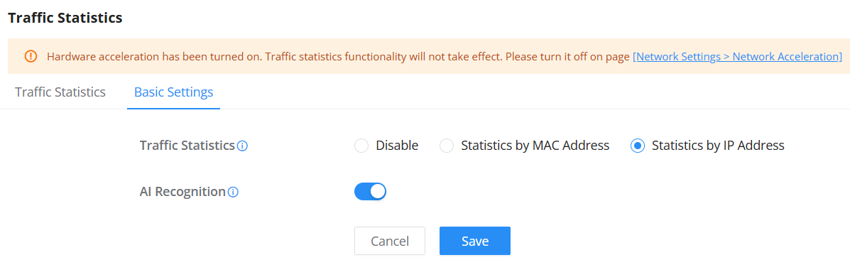
| Field | Description |
|---|---|
| Traffic Statistics | Select how traffic data is collected: • Disable • Statistics by MAC Address – Recommended for LAN device management and security control. • Statistics by IP Address – Recommended for WAN-level traffic analysis. |
| AI Recognition | Enable AI deep learning to improve application classification accuracy. May increase CPU and memory usage. |
| Note | Traffic statistics are inactive if Hardware Acceleration is turned on. |
QoS
Quality of Service (QoS) is a feature that allows the prioritization of the latency-sensitive traffic exchanged between the WAN and the LAN hosts. This will offer more control over the usage of a limited bandwidth and ensure that all application services are not affected by the amount of traffic exchanged.
General Settings
On this page, the user will be able to allocate a percentage of the download and the upload bandwidth to 4 classes. These classes can be assigned to applications to determine which application traffic will be prioritized, including the inbound and the outbound traffic. Also, it’s possible to tag outbound traffic with DSCP tags for each class.
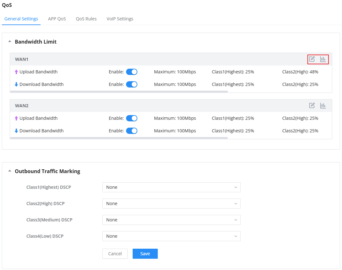
To set the upload/download bandwidth percentage for each class, click on the edit button  .
.
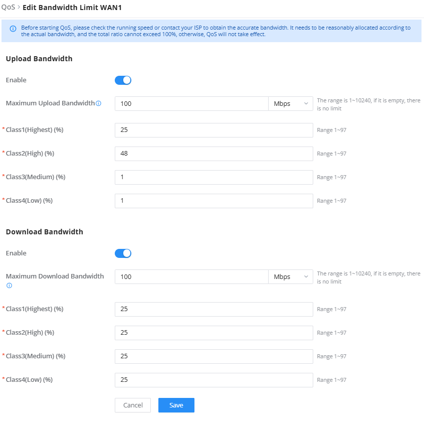
Upload/Download Bandwidth | |
Status | Toggle QoS for the WAN port on/off |
Maximum Upload/Download Bandwidth | Specify the maximum upload/download speed for the WAN port. The supported range is 1–2560 Mbps. |
Class1 (High) | Specify the bandwidth percentage allocated for Class 1. |
Class2 (Medium) | Specify the bandwidth percentage allocated for Class 2. |
Class3 (Low) | Specify the bandwidth percentage allocated for Class 3. |
Class4 (Lowest) | Specify the bandwidth percentage allocated for Class 4. |
Edit Bandwidth limit
Click on the  bandwidth statistics icon to get a general overview of the upload/download bandwidth status.
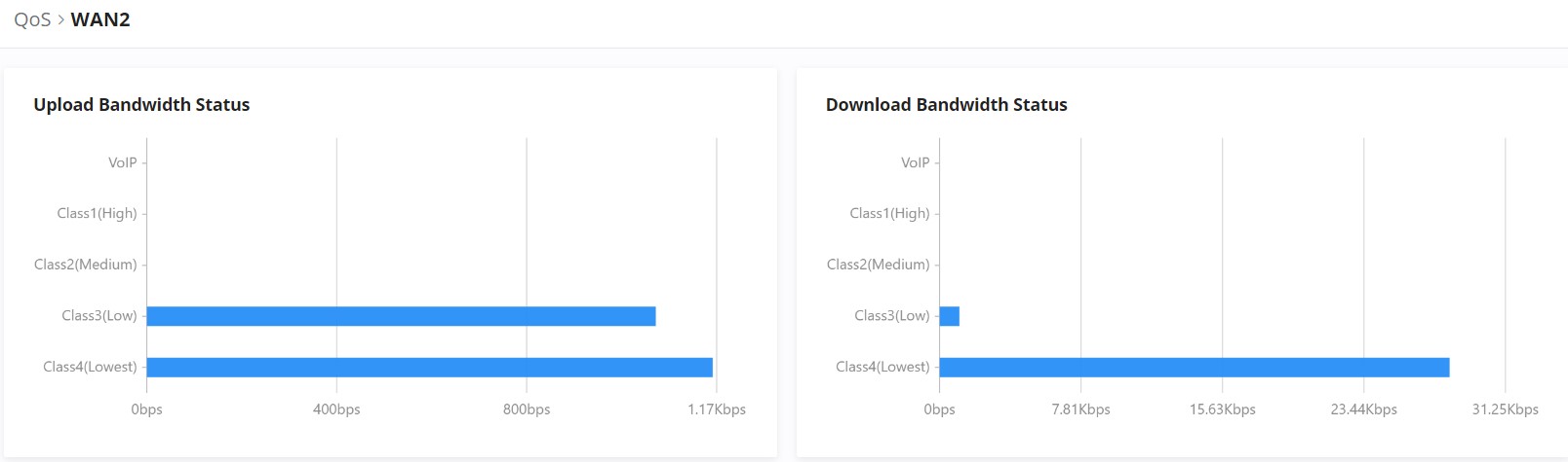
APP QoS
GCC601X(W) can prioritize the traffic of applications by category or individually. The priority level can be set in 4 classes, class 1 having the highest priority and class 4 having the lowest priority. To access APP Class settings, please access the web GUI of the router, then navigate to Traffic Management → QoS → APP QoS.
- Application Priority
Under Application Priority, users can select a category, then specify the priority (Highest, High, Medium, Low, or None). Please check the figure below:
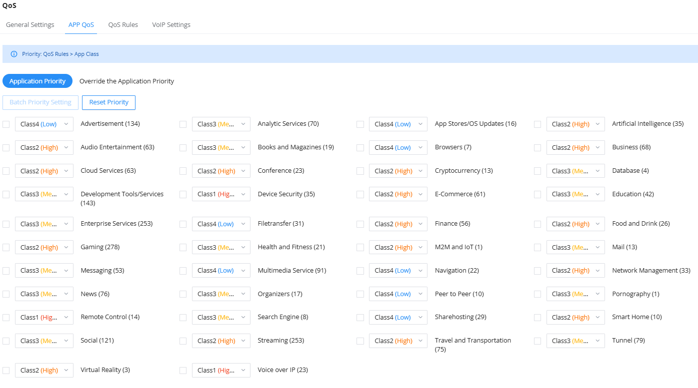
It’s also possible to select many categories and then click on “Batch Settings” to apply QoS Priority on all of them at once.
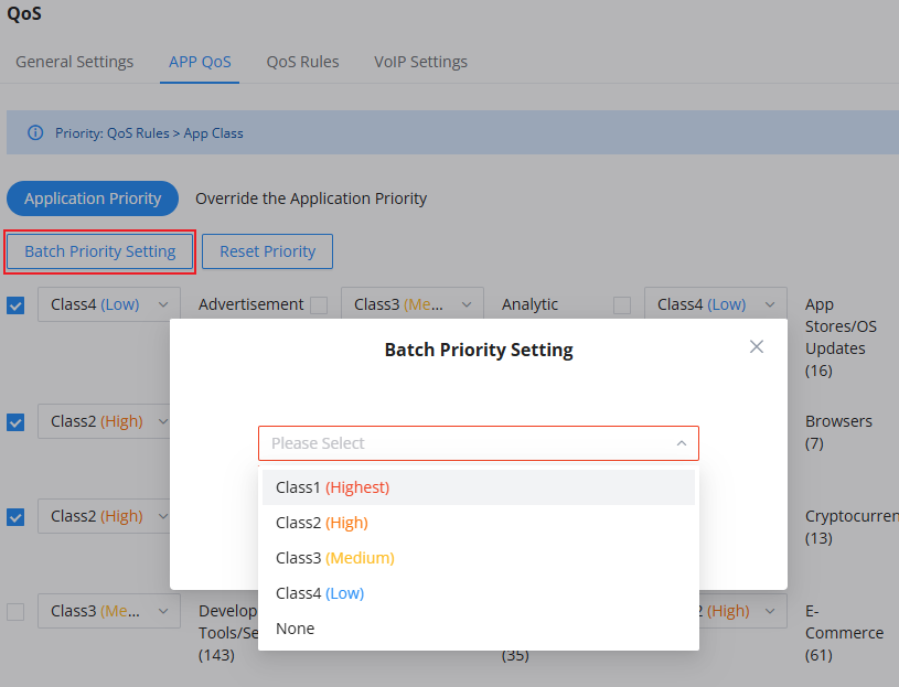
- Override the Application Priority
The previous option (Application Priority) applies the priority to the whole category. If the users want to make an exception or add a specific application, under “Override the Application Priority“, click on the “Add” button as shown below:

Then, select the specific applications even from different categories, and after that, select the QoS priority from the drop-down list. This will override the Application Priority applied to the whole category.
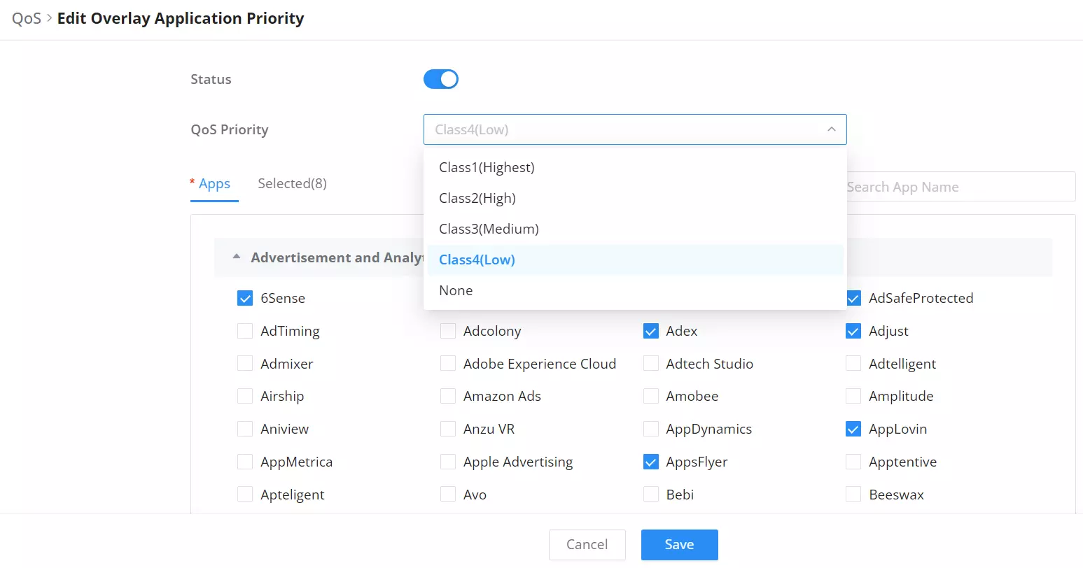
QoS Rules
QoS class rules are rules that set the QoS based on source and/or destination IP addresses, and source and destination ports.
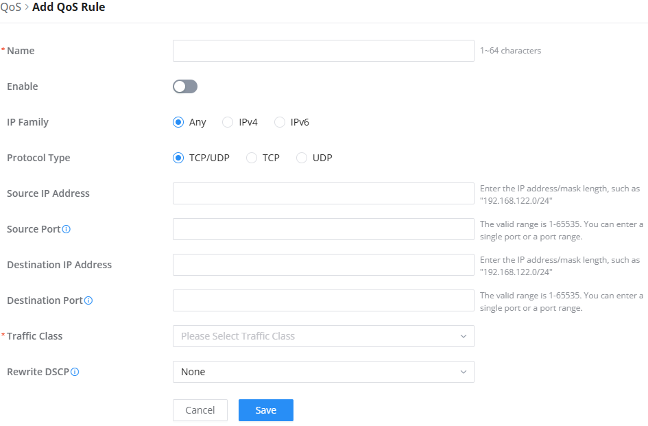
Name | Enter the name of the class. The character limit is 1-94 characters. |
Enable | Turns the QoS rule on or off without deleting it. |
IP Family | Choose the IP family:
|
Protocol Type | Choose the protocol type:
|
Source IP Address | Enter the source IP address/mask length. E.g.,”192.168.122.0/24″ |
Source Port | Enter a single port number, multiple port numbers, or a range of ports number. Example: – To enter a single port number, type the port number such as “3074”. – To enter multiple port numbers, type the port numbers with a comma in between each port number, such as “3074, 5060, 10000”. – To enter a range of port, enter the first port number in the range, then type a dash (-) and enter the last port number in the range. E.g., “10000-20000” Note: The valid range of port numbers that can be entered is 1-65535. |
Destination IP Address | Enter the destination IP address/mask length. E.g.,”192.168.122.0/24″ |
Destination Port | Enter a single port number, multiple port numbers, or a range of ports number. Example: – To enter a single port number, type the port number such as “3074”. – To enter multiple port numbers, type the port numbers with a comma in between each port number, such as “3074, 5060, 10000”. – To enter a range of port, enter the first port number in the range, then type a dash (-) and enter the last port number in the range. E.g., “10000-20000” Note: The valid range of port numbers that can be entered is 1-65535. |
Traffic Class | Assigns a priority class (e.g., Class1 (Highest), Class2, Class3, Class4) to determine traffic handling. |
Rewrite DSCP | The DSCP for the current priority overrides the DSCP of the corresponding priority in the outbound traffic marking, and takes precedence. |
QoS – Add Class Rules
VoIP Settings
The VoIP Prioritization feature on the GCC601X(W) enhances the quality of voice communication by prioritizing VoIP traffic such as SIP and PBX. These settings ensure that voice data takes precedence over other network traffic, improving the reliability and quality of phone calls.
To configure these settings, navigate to Traffic Management → QoS → VoIP Settings in the Web UI.
- SIP Service Configuration
- Go to Traffic Management → QoS → VoIP Settings.
- Select the SIP Service tab.
- Toggle SIP Prioritization to enable prioritization for SIP traffic.
- Enter the SIP UDP Port (default is 5060).
By enabling this setting, VoIP SIP traffic is given priority over other types of data traffic, ensuring better voice communication quality.

- PBX Service Configuration
- Go to Traffic Management → QoS → VoIP Settings.
- Select the PBX Service tab.
- Click Add to configure a new PBX service.
- Fill in the necessary fields (explained in the table below).
- After adding, enable the PBX service to prioritize traffic for this specific server.


| Field | Description |
|---|---|
| Name | Descriptive name for the PBX server (e.g., Local PBX or Backup PBX). |
| IP Address | The IP address of the PBX server that will handle the VoIP traffic. |
| Port | Range 1-65535; enter multiple ports separated by commas, e.g., 4, 6-10; leave blank for all ports. |
Once configured, PBX traffic is prioritized, ensuring consistent quality for calls routed through the designated PBX servers.
Bandwidth Limit
The Bandwidth Limit feature helps to limit bandwidth by specifying the maximum upload and download limit; then this limit can be applied to each IP/MAC address or applied to all IP addresses in the IP address range. Navigate to Web UI → Traffic Management → Bandwidth Limit.
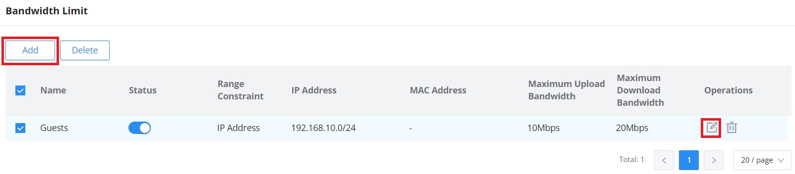
To add a bandwidth rule, please click on the “Add” button or click on the “Edit” icon as shown above.
Please refer to the figure below:
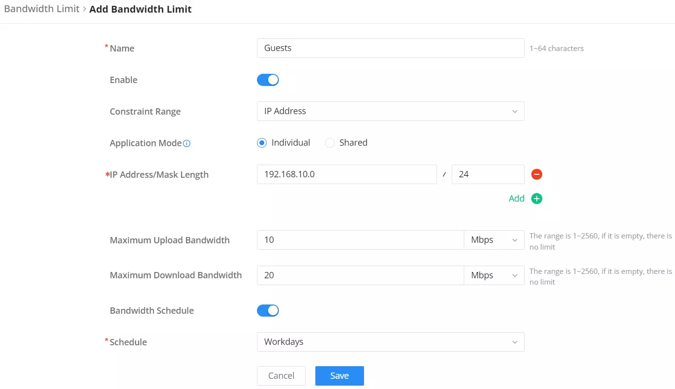
Name | Enter a name for this rule. (1-64 characters) |
Enable | Enable/disable the rule |
Constraint Range | Select the constraint range:
Default is “IP Address” |
MAC Address | Specify the MAC address when the “Constraint Range” is set to “MAC Address” |
Application Mode | Individual: Set the maximum upload bandwidth and maximum download bandwidth that can be used by each IP address/IP address segment. Shared: Set the sum of the maximum upload bandwidth and maximum download bandwidth that can be used by all IP addresses in the IP address range. Note: It applies to “Constraint Range = IP Address” only |
IP Address/Mask Length | Set the IP Address(es) and thier maskes. Note: It applies to “Constraint Range = IP Address” only |
Maximum Upload Bandwidth | Set the Maximum Upload Bandwidth. The range is 1~2560, if it is empty, there is no limit |
Maximum Download Bandwidth | Set the Maximum Download Bandwidth. The range is 1~2560, if it is empty, there is no limit |
Bandwidth Schedule | Enabled or disable Bandwidth schedule. |
Schedule | Select or add a schedule to apply. |
Add or Edit Bandwidth rule
Intelligent Speed Limit
When intelligent speed limit is enabled, it automatically limits the speed of download or upload traffic when the CPU load is high.
To enable Intelligent Speed Limit, navigate to Traffic Management → Intelligent Speed Limit, then toggle ON the feature.
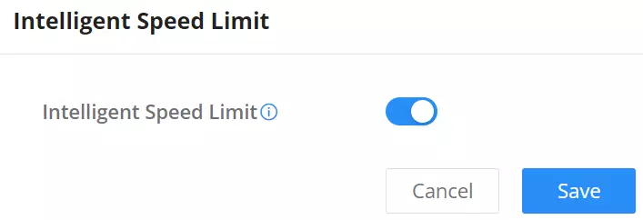
ACCESS CONTROL
SafeSearch
The GCC601X(W) offers a SafeSearch feature on Bing, Google, and YouTube. Enabling this option will hide any inappropriate or explicit search results from being displayed.
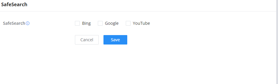
Network Sharing Control
Network Sharing Control prevents a client connected to the LAN from redistributing its network connection through a mobile hotspot, personal router, or another forwarding device.
Wireless service and this protection are configured in separate GCC modules. Create or edit the SSID under Network Nodes → Wi-Fi Management → SSIDs, and associate the SSID with the required network or VLAN. After wireless clients connect and receive IP addresses from that network, configure this feature under Networking → Access Control → Network Sharing Control. Network Sharing Control applies to client IP traffic handled by the GCC and is not attached directly to an individual SSID.
When the feature is enabled, the GCC sets the Time to Live (TTL) value of packets sent to LAN clients to 1. The intended client can receive the traffic normally. If that client attempts to forward the traffic to another device, the additional routing hop reduces the TTL to 0 and the packet is discarded. This prevents the downstream device from using the shared connection.
- Create or confirm the SSID and its associated network or VLAN under Network Nodes → Wi-Fi Management → SSIDs.
- Navigate to Networking → Access Control → Network Sharing Control, then enable Network Sharing Control.
- If selected clients must remain allowed to share their connection, add them under IP Exception using the appropriate address method.
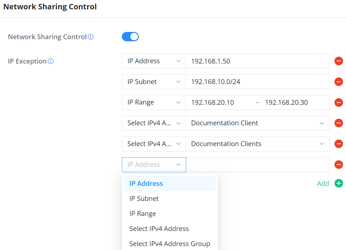
| Parameter | Description |
|---|---|
| Network Sharing Control | Enables or disables the TTL-based restriction that prevents LAN clients from forwarding their connection to downstream devices. |
| IP Exception | Defines the clients that are allowed to share their network connection while Network Sharing Control is enabled. |
| IP Address | Exempts one directly entered IPv4 address. |
| IP Subnet | Exempts every IPv4 address within the specified subnet and prefix length. |
| IP Range | Exempts every IPv4 address from the specified starting address through the ending address. |
| Select IPv4 Address | Exempts a previously saved, reusable IPv4 address object. |
| Select IPv4 Address Group | Exempts a previously saved group containing one or more IPv4 address objects. |
EXTERNAL ACCESS
By default, all the requests initiated from the WAN side are rejected by the GCC601X(W) external access features allow hosts located on the WAN side to access the services hosted on the LAN side of the GCC601X(W).
DDNS
Dynamic Domain Name System (DDNS) allows users to map a dynamic IP address to a fixed domain name, making it easier to access devices on networks where the IP address may change. This is especially useful for remote access to networked devices without requiring a static IP.
GCC6000 devices support DDNS configuration, enabling seamless remote access through a consistent domain name, regardless of IP changes. Key features include:
- Multiple Provider Support: Choose from popular DDNS providers to match your existing account.
- Public IP Detection: When positioned behind a NAT, the GCC6000 devices can detect and register the public IP address for accurate DDNS updates.
- Customizable Update Intervals: Set the frequency of updates to ensure the DDNS server always has the current IP address.
- Interface Selection: Specify the WAN interface used for DDNS, allowing flexibility in multi-WAN environments.
These features make the GCC6000 devices ideal for environments requiring reliable remote access, even in networks with dynamic IP addresses.

Field | Description |
Service Provider | Dropdown selection of available Dynamic DNS providers (e.g., dyndns.org, changeip.com, etc.). Note: Requires registration at the chosen provider’s website to obtain the domain, username, and password for DDNS services. Custom option allowing you to manually configure any third-party DDNS service by providing the update URL and parameters. |
Service Provider Name | Set the Service Provider Name. (1-64 characters) Note: This field appears only when “Service provider” is sset to “Custom”. |
Service Provider URL | Fill in the URL format according to the service provider’s URL format specifications and ensure that the URL contains http:// or https:// protocol type and the <domain>, <ip>, <username>, and <password> placeholders. Example: https://ddns.example.com/update?hostname=<domain>&myip=<ip>&username=<username>&password=<password> Note: This field appears only when “Service provider” is sset to “Custom”. |
Enable | Toggle to enable or disable the DDNS service for the selected provider. |
Username | Enter the username provided by the DDNS service provider. Range: 1-32 characters. |
Password | Enter the password associated with the DDNS service provider. Range: 1-32 characters. |
Domain | Enter the domain or hostname to be updated by the DDNS service. |
Interface | Select the WAN interface to associate with the DDNS update. |
IP Source | Choose between ‘WAN IP’ or ‘Public IP’ for the source of IP to send to the DDNS provider. Default: WAN IP. Note: Use ‘Public IP’ if behind a NAT to detect and use the device’s public IP address for the DDNS update |
Update Interval (Min) | Set the interval in minutes for updating the IP address of the device to the DDNS server. Default: 10. Range: 1-1440. Note: Increasing interval reduces frequency of updates to the DDNS server |
DDNS Page
Port Forwarding
Port forwarding allows forwarding requests initiated from the WAN side of the GCC601X(W) to a LAN host. This is done by configuring either the port only or the port and the IP address in case we want to restrict access over that specific port to one IP address. Once the GCC601X(W) receives the request on the IP address, the GCC601X(W) will verify the port on which the request has been initiated and will forward the request to the host IP address and the port of the host which is configured as the destination.
Port forwarding can be used in the case when a host on the WAN side wants to access a server on the LAN side.
Navigate to External Access → Port Forward:
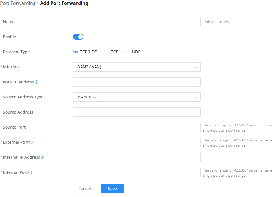
Refer to the following table for the Port Forwarding option when editing or creating a port forwarding rule:
Name | Enter a name for the port forwarding rule. |
Status | Toggle on/off the rule status. |
Protocol Type | Select the transport protocol used.
|
Interface | Select the WAN port |
WAN IP Address | Enter the WAN IP address for Internet clients to access this server; if an interface is selected, leave this field blank and all IP addresses on that interface can be used for port forwarding. |
Source Address Type | Select the address type that will be entered
|
Source Address | Sets the IP address that external users access to this device. If not set, any IP address on the corresponding WAN port can be used |
Source Port | Set a single or a range of Ports. |
External Port | The service port that the router provides to the WAN. External users obtain services by sending requests to this port. You can enter a port number or a range of ports (e.g. 5-23). |
Internal IP Address | Set the The IP address of the network host acting as the server in the LAN IP address. |
Internal Port | The service port provided by the router to the local network, i.e. the LAN service port. If the source port is entered in a range, the destination port must also be entered in a range, and the port range difference must be consistent (for example, the source port can be entered as 10-20, and the destination port can be entered as 11-21, and the port range difference is 10). |
Port Forwarding page
The Port Forwarding page includes a Clone button, allowing administrators to quickly duplicate existing port forwarding rules. This simplifies the creation of similar rules without manual re-entry.
To clone a rule, select the desired entry and click Clone. The duplicated rule can then be edited if needed before saving.

DMZ
Configuring the DMZ, the GCC601X(W) will allow all external access requests to the DMZ host. This is
This section can be accessed from Web GUI → External Access → DMZ.
GCC601X(W) supports DMZ, where it is possible to specify a Hostname IP Address to be put on the DMZ.
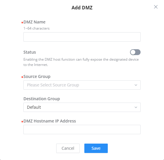
Enabling the DMZ host function, the computer set as the DMZ host can be completely exposed to the Internet, realizing two-way unrestricted communication.
Refer to the table below for DMZ fields:
DMZ Name | Enter a name for the DMZ rule. |
Status | Toggle on/off the status of the DMZ rule. |
Source Group | Select the interface to allow access to the DMZ host. |
Destination Group | Select the VLAN on which the DMZ host belong. |
DMZ Hostname IP Address | Enter the DMZ host IP address. |
DMZ Page
UPnP
GCC601X(W) supports UPnP that enables programs running on a host to configure automatically port forwarding.
UPnP allows a program to make the GCC601X(W) open necessary ports, without any intervention from the user, without making any checks.
UPnP settings can be accessed from GCC601X(W) Web GUI → External Access → UPnP.
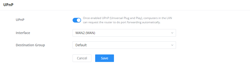
UPnP | Click on “ON” to enable UPnP. Note: Once enabled UPnP (Universal Plug and Play), computers in the LAN can request the router to do port forwarding automatically |
Interface | Select the interface (WAN) |
Destination Group | Select the LAN Group |
UPnP Settings
When UPnP is enabled, the ports will be shown in the section below. The information shown includes the application name, IP address of the LAN host that has requested the opening of the port, the external port number, the internet port number, and the transport protocol used (UDP or TCP).
TURN Service
TURN stands for Traversal Using Relays around NAT, and it’s a network service that helps establish peer-to-peer connections between devices that are behind a NAT or Firewall. Real-time communication like video conferencing, Voice over IP, etc benefit from the TURN service to establish connections between peers when the NAT or the Firewall blocks or modifies the traffic.
Navigate to Web UI → External Access → TURN Service. The service is OFF by default; toggle Status ON to turn on the service. The default TURN Server Port is 3478; it is also possible to add or remove a username and password by clicking the “minus” and “Plus” icons.
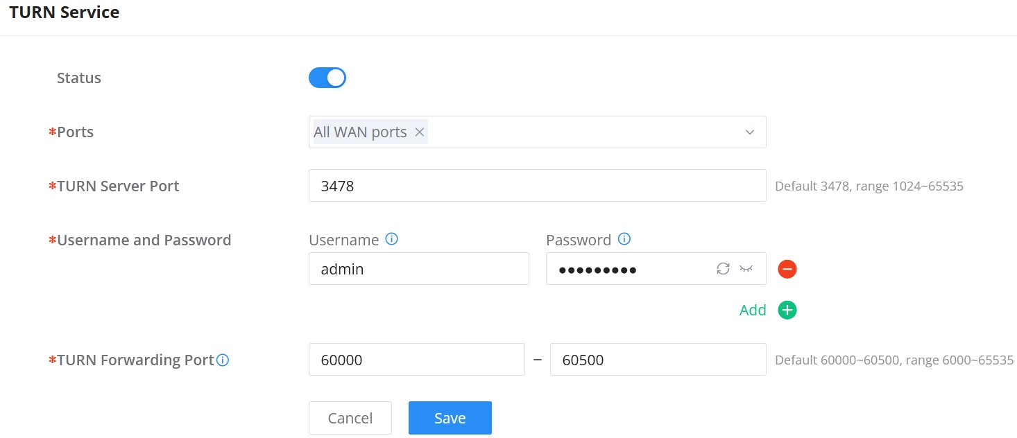
MAINTENANCE
GCC601X(W) offers multiple tools and options for maintenance and debugging to help further troubleshooting and monitoring the GCC601X(W) resources.
TR-069
It is a protocol for communication between CPE (Customer Premise Equipment) and an ACS (Auto Configuration Server) that provides secure auto-configuration as well as other CPE management functions within a common framework.
TR-069 stands for a “Technical Report” defined by the Broadband Forum that specifies the CWMP “CPE WAN Management Protocol”. It commonly uses HTTP or HTTPS as transport for communication between CPE and the ACS. The message exchange uses SOAP (XML_RPC) for the configuration and management of the device.
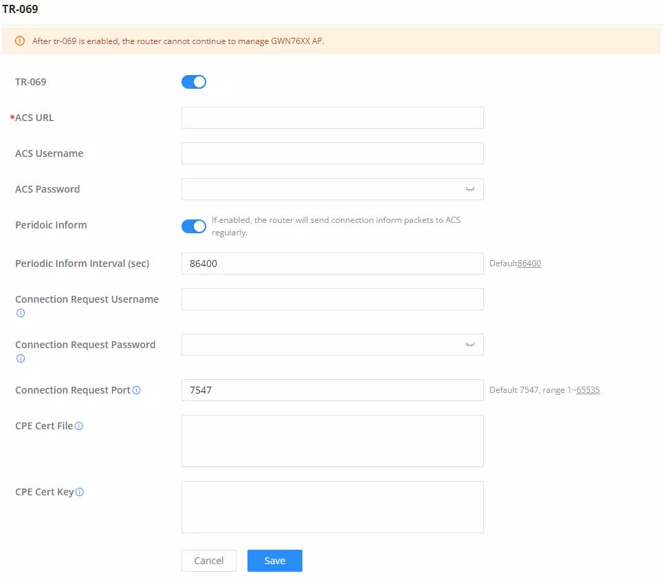
TR-069 | Enable/disable TR-069 |
ACS URL | Enter the FQDN or the IP address of the ACS server. |
ACS Username | Enter the username. |
ACS Password | Enter the password. |
Periodic Inform | If enabled, the GCC6020 will send connection inform packets to ACS regularly. |
Periodic Inform Interval (sec) | This configures the time duration between each inform sent by the device to the ACS server. |
Connection Request Username | When ACS server sends a connection request to the device, the username that the device authenticates ACS must be consistent with the configuration of ACS side. |
Connection Request Password | The password that the device authenticates ACS must be consistent with the configuration of ACS server. |
Connection Request Port | The port for ACS to send connection request to the GCC6020. This port cannot be occupied by other device features. |
CPE Cert File | Enter the certificate that the device needs to use when connecting to ACS through SSL. |
CPE Cert Key | Enter the certificate key that the device needs to use when connecting to ACS through SSL. |
TR-069 page
SNMP
GCC601X(W) supports SNMP (Simple Network Management Protocol), which is widely used in network management for network monitoring to collect information about monitored devices.
To configure SNMP settings, go to Web GUI → Maintenance → SNMP. On this page, the user can either enable SNMPv1, SNMPv2c, or SNMPv3, and enter all the necessary parameters.
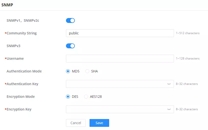
To configure SNMPv1 or SNMPv2, please refer to the table below:
SNMPv1, SNMPv2 | Enable/disable SNMPv1 and SNMPv2 |
Community String | Enter the shared password of the community. |
SNMP – SNMPv1 or SNMPv2
To configure SNMPv3, please refer to the table below:
SNMPv3 | Enable/disable SNMPv3. |
Username | Enter a username. |
Authentication Mode | Select the algorithm used for the authentication. |
Authentication Key | Select the authentication password. |
Encryption Mode | Select the encryption protocol used for the encryption of the data. |
Encryption Key | Enter the encryption key. |
SNMP – SNMPv3
System Diagnostics
Many debugging tools are available on GCC601X(W)’s Web GUI to check the status and troubleshoot GCC601X(W)’s services and networks.
To access these tools, navigate to “Web UI → System Settings → System Diagnosis“
Capture
This section is used to capture packet traces from the GCC601X(W) interfaces (WAN ports and network groups) for troubleshooting purposes or monitoring. It’s even possible to capture based on MAC address or IP Address; once done, the user can click the “Start Capturing” button and the file (CAP) will start downloading right away. It’s also possible to select the storage location (internal storage, USB, microSD, or SSD) if available.

If a storage option is available and the capture file is stored on it, the storage option tab will list the available capture files to download to your local machine or delete to save storage.

One-click Debug
The One-click Debug feature allows administrators to capture system logs and diagnostic data automatically for troubleshooting purposes. It runs a background process and provides a downloadable file with debugging results.
How It Works:
- Click Start to begin capturing logs.
- The process will stop automatically if:
- It exceeds 30 minutes, or
- The debug file reaches 20MB.
- Once completed, the debug result can be downloaded using the download icon.
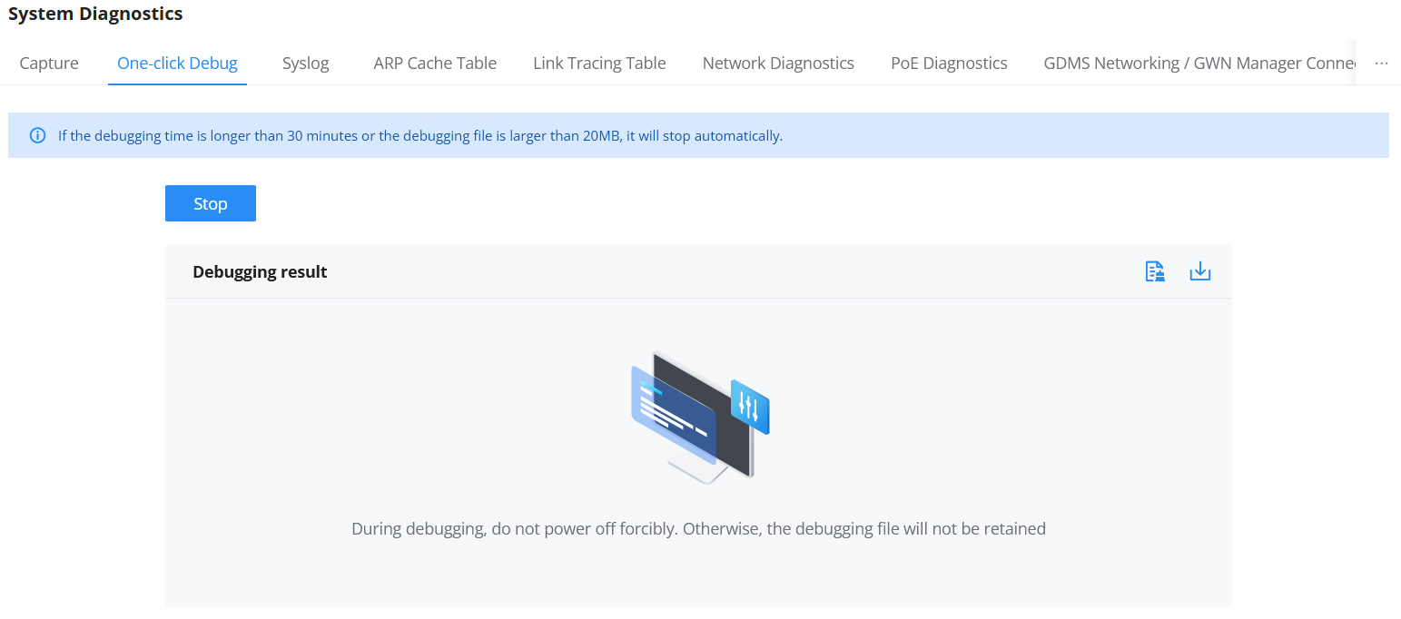
Important Notes:
- Do not power off the device during debugging; otherwise, the debug file will not be saved.
- Use this tool when requested by support or when diagnosing persistent system issues.
Syslog
The Syslog page allows you to collect and manage system logs for Networking, Network Nodes, and Firewall modules. Logs can be stored locally or forwarded to an external syslog server using standard protocols.
GCC601X(W) supports dumping the Syslog information to a remote server under Web GUI → System Settings → System Diagnosis → Syslog Tab
Enter the Syslog server Hostname or IP address and select the level for the Syslog information. Nine levels of Syslog are available: None, Emergency, Alert, Critical, Error, Warning, Notice, Information, and Debug.
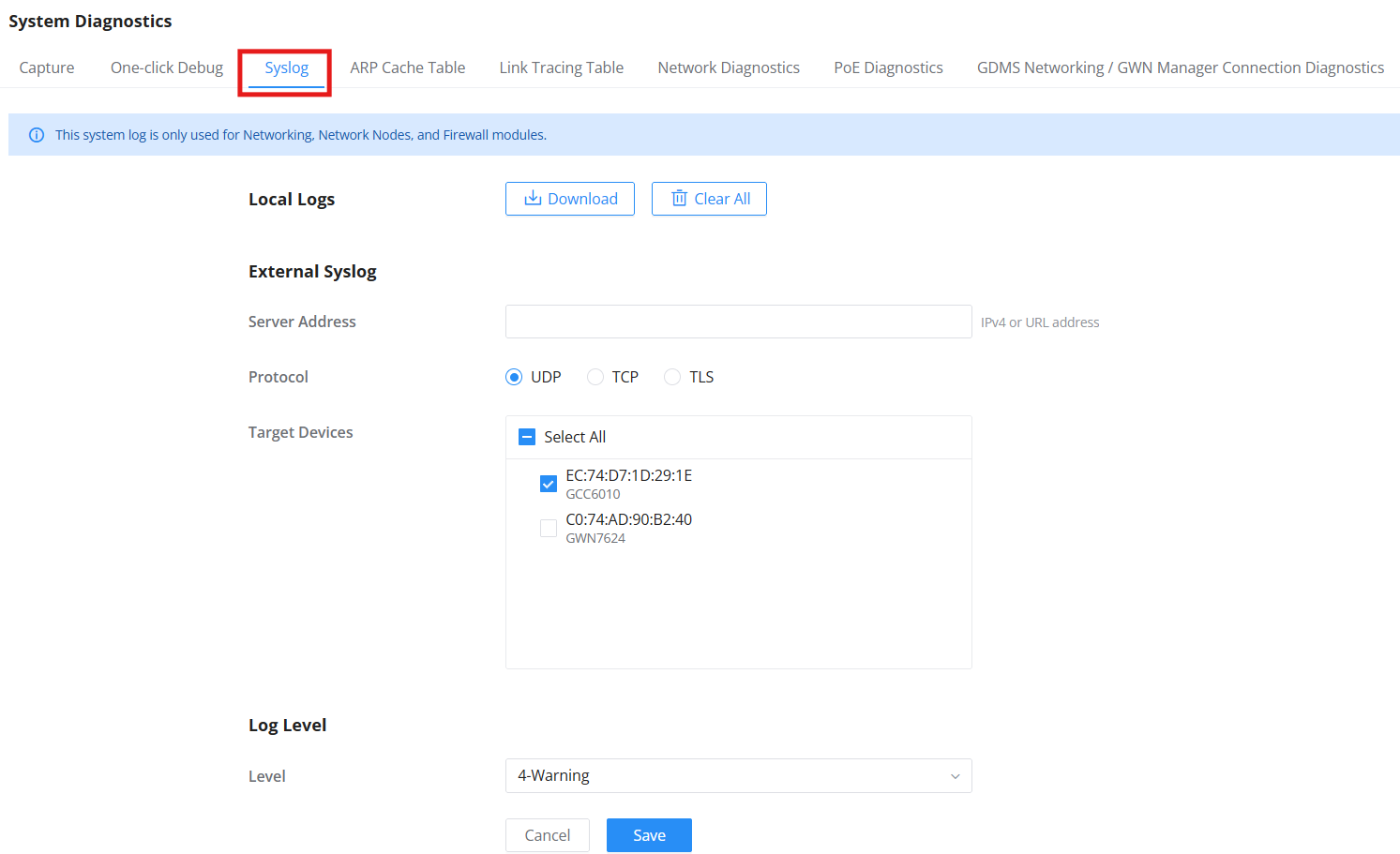
| Field | Description |
|---|---|
| Local Logs | View and manage stored logs directly on the device. • Download – Export logs as a file. • Clear All – Delete all stored logs. |
| Server Address | Enter the IPv4 or URL of the external syslog server. |
| Protocol | Select the transport protocol: UDP, TCP, or TLS. |
| Target Devices | Select one or more devices to monitor with the syslog output. |
| Log Level | Choose the minimum severity level to be captured: • None • Debug • Info • Notice • Warning • Error • Critical • Alert • Emergency |
Notes:
- This system log applies only to Networking, Network Nodes, and Firewall modules.
- Be sure to configure an appropriate log level to avoid unnecessary noise or missed issues.
ARP Cache Table
GCC601X(W) keeps an ARP table record of all the devices that have been assigned an IP address from the GCC601X(W). The record will keep the device’s information when the device is offline. To access the ARP Cache Table, please navigate to System Diagnostics → ARP Cache Table.
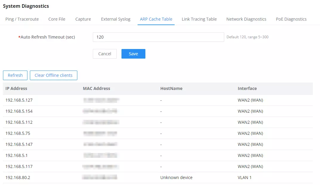
Link Tracing Table
The Link Tracing Table shows the flow of traffic by displaying the source IP address/Port (the green color) and the reply IP address/port (the blue color); other information can also be displayed, such as IP Family, Protocol Type, Life Time, Status, Packets/Bytes, etc.
Users/Administrators can also delete the flow of certain IP addresses/Ports (Source and Destination) or then click on the “Delete” button to clear the link tracing statistics.
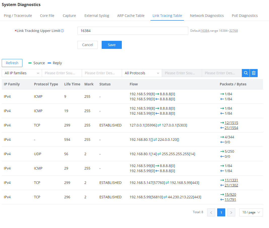
Network Diagnostics
The Network Diagnostics feature allows the user to quickly diagnose the connection link on a specific WAN interface.

PoE Diagnostics
The PoE Diagnostics page offers insight about the ports and their components as well as the power used and the temperature. The information provided can be useful when the user encounters an issue with the PoE function of the GCC601X(W).
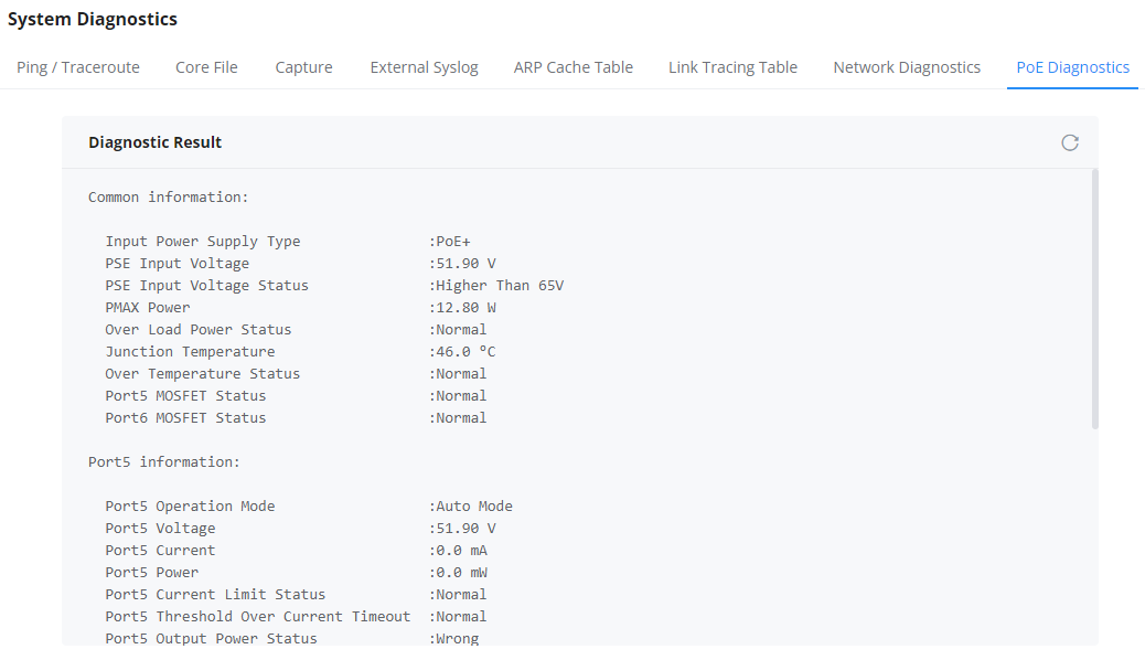
Cloud/Manager Connection Diagnostics
When the GCC601x(W) device is added to GWN.Cloud or GWN Manager, users can check the connection status (connected or not) and even diagnose the problem.
Network tools
Ping/Traceroute/NSlookup
The Network Tools section provides essential diagnostic utilities to troubleshoot network connectivity issues. You can select between Ping, Traceroute, and NSlookup to verify reachability and trace network paths to a remote host.
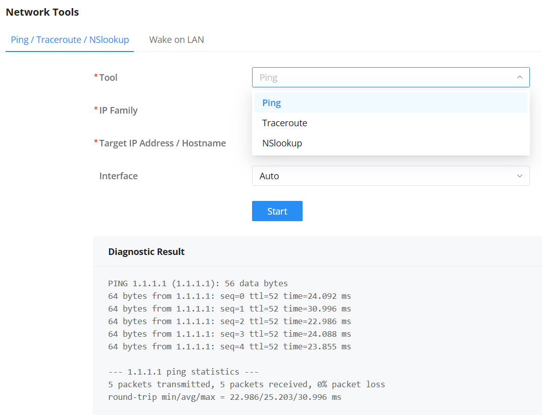
| Field | Description |
|---|---|
| Tool | Choose the diagnostic method: • Ping – Tests connectivity to a host. • Traceroute – Displays the path packets take to reach the destination. • NSlookup – Resolves domain names to IP addresses. |
| IP Family | Select IPv4 or IPv6 for the test. |
| Target IP Address / Hostname | Enter the destination address or domain name to test. |
| Interface | (Optional) Select the interface to use for testing. Default is Auto. |
| Start | Click to execute the selected test. |
Diagnostic Result:
After running a tool, the result is displayed in the Diagnostic Result section below the form, showing real-time output for the selected diagnostic.
Wake on LAN
The Wake on LAN feature allows administrators to remotely power on devices within the same LAN using a “magic packet.” Devices must be connected via wired Ethernet for this function to operate correctly.
How to Use
- Click Add to register a device.
- Choose to:
- Add Manually: Enter the device’s MAC address and description.
- Discovered Devices: Select from detected devices on the LAN.
- (Optional) Enable Schedule Wakeup to automate power-on at a defined time.
- Click Save to finalize the configuration.
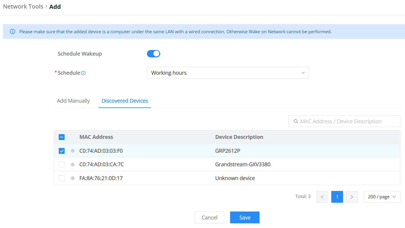
Field Descriptions:
| Field | Description |
|---|---|
| Schedule Wakeup | Enable to send automatic wake-up signals based on a defined schedule. |
| Schedule | Select a predefined time for automated wake-up commands. |
| MAC Address | Unique hardware address of the target device. |
| Device Description | Optional label to identify the device. |
Alerts & Notifications
Alerts
The Alerts page displays alerts about the network; the user can specify to display only certain types (System, Performance, Security, or Network) or the levels. To check the alerts that have been generated, please navigate to Maintenance → Alerts & Notifications page → Alerts tab.
The alerts can be displayed either by type or level. However, that is not the only way to display them. The user can filter through the alert log using a date interval or search by MAC address or device name.
Alerts Types
The available types are System, Performance, Security, and Network, or the user can choose to display all the types.
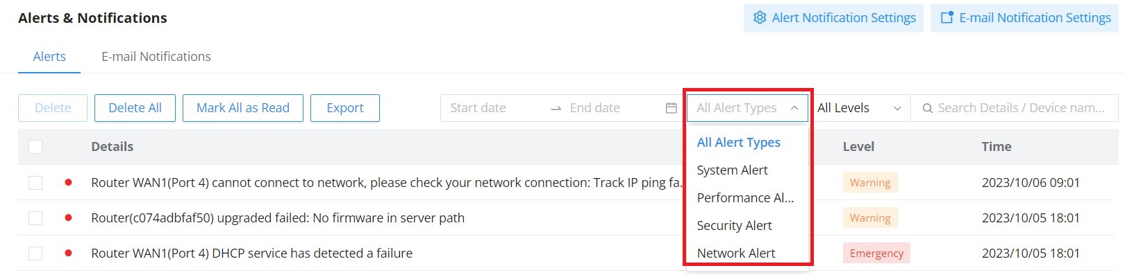
Alerts Levels
The user can filter the alert level by the following levels: All Levels, Emergency, Warning or Notice.
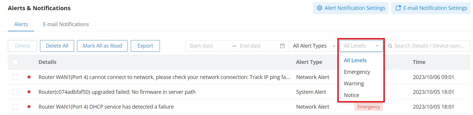
Alert Notification Settings
To enable the notifications on the Alerts tab, please click on the “Alert Notification Settings” button as shown below:
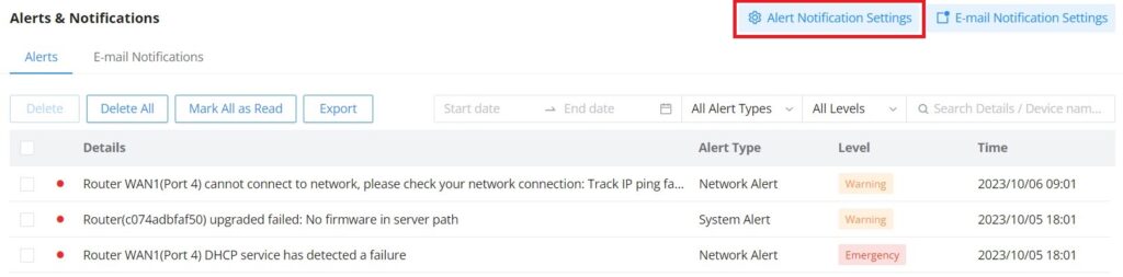
The figures below show all the possible alert notifications that the user can enable on the Alerts tab, organized into 4 categories: System Alert, Performance Alert, and Network Alert.
Please refer to the figures below:

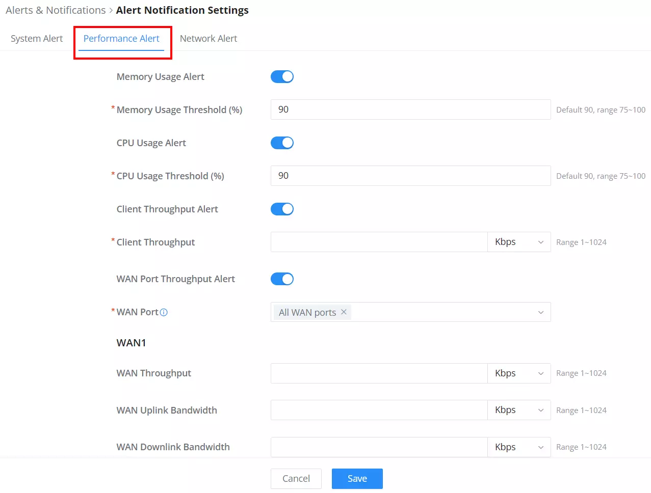
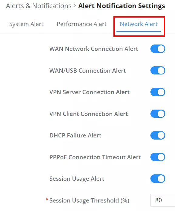
E-mail Notifications
On this tab, the user can set up the E-mails that will receive the notifications. Once the feature is enabled, the user can fill in the fields according to SMTP parameters. Refer to the figure below:
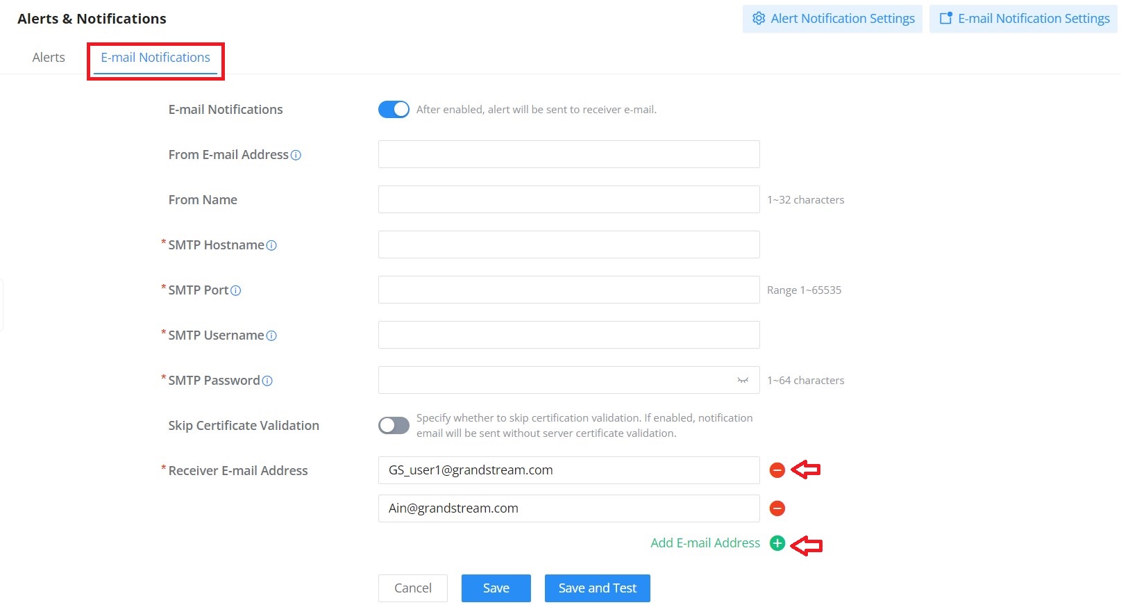
It’s possible to add more than one receiver E-mail address as shown in the figure above.
- Click on the “Minus” icon to delete the receiver’s E-mail address.
- Click on the “Plus” icon to add the receiver’s E-mail address.
E-mail Notification Settings
To select what notifications will be sent to the receiver’s E-mail addresses, please click on the “E-mail Notification Settings” button as shown below:
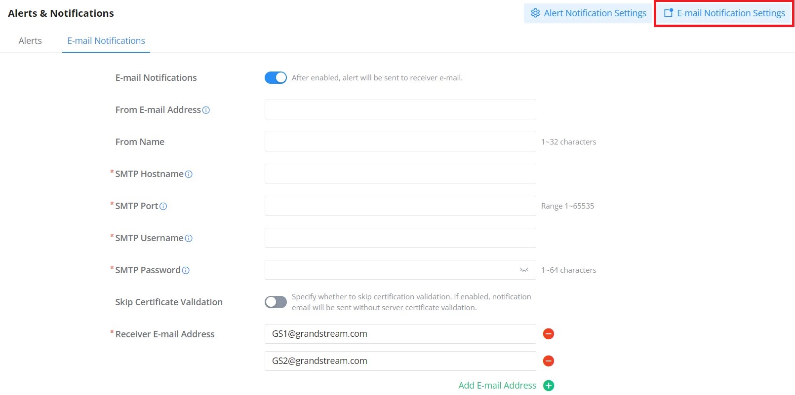
The figures below show all the possible E-mail notifications that the user can send to the pre-configured receiver E-mail Addresses, organized into 4 categories:
- System
- Performance
- Network

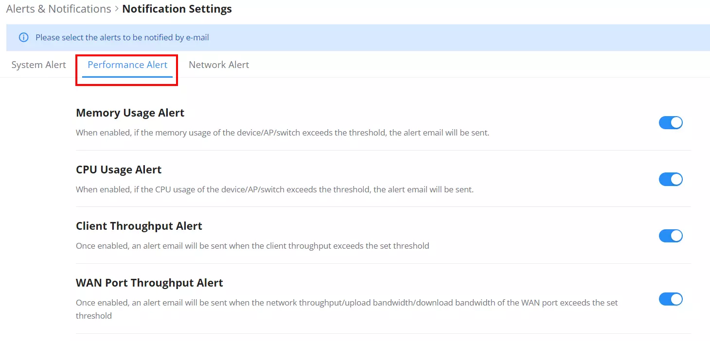
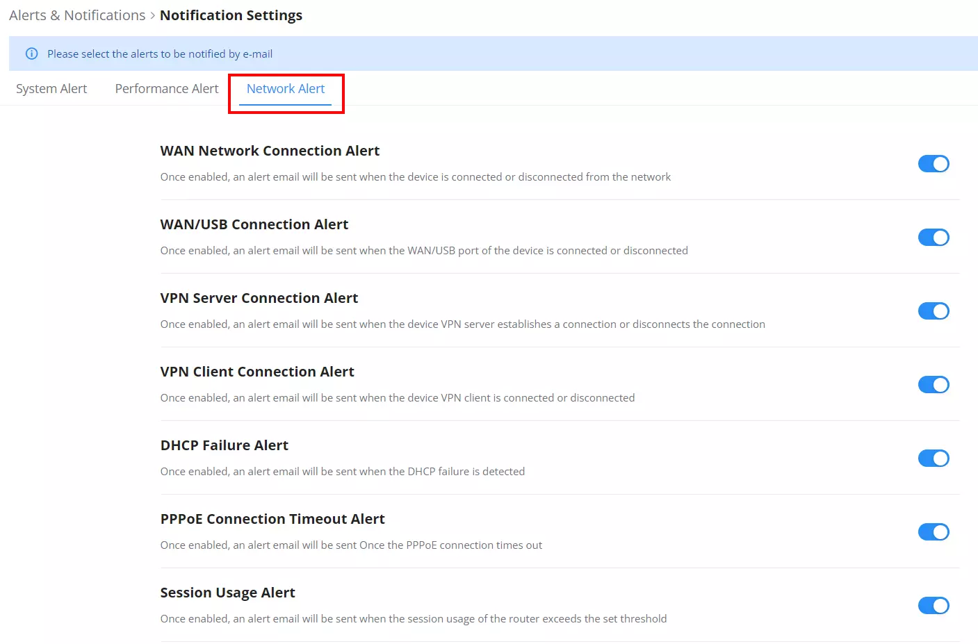
SYSTEM SETTINGS
Email Settings
The Email Settings page allows administrators to configure system email notifications. When enabled, alerts are sent to the specified recipient addresses. This is typically used for system events, errors, or important status updates.
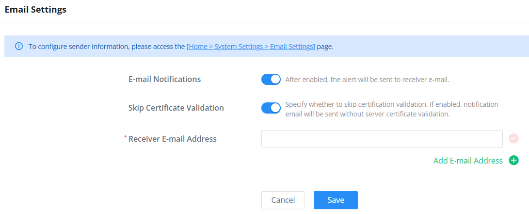
Field Descriptions:
| Field | Description |
|---|---|
| E-mail Notifications | Toggle to enable or disable alert email notifications. |
| Skip Certificate Validation | When enabled, the system will bypass server certificate checks when sending email. Use with caution. |
| Receiver E-mail Address | Enter the recipient email address(es) that will receive notifications. Use Add to include multiple. |
Note: To configure the sender email information, go to: Home → System Settings → Email Settings.
File Sharing
The GCC601X(W) devices allow users to share files over the network using USB flash drives, external hard drives, and microSD cards.
When a supported storage device is connected, it will appear in the External Device List and can be accessed by clients on the local network.
Clients can access shared directories using:
- Windows:
file://<IP address> - Mac/Linux:
smb://<IP address>
Supported formats: ext4 (recommended), exFAT, FAT32, F2FS, NTFS
You can also enable or disable Anonymous Login for access control.
Navigate to System Settings → File Sharing.
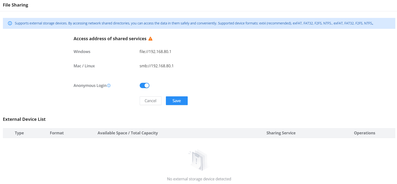
Profiles
MAC Group
The MAC Group is a feature in GCC devices that enables the user to create a group of MAC addresses from the available ones or manually add the MAC Address.
To create a new MAC group, navigate to: “Profiles → MAC Group“ then click the “Add” button.
- Add devices from the list:
Enter the name of the MAC Group, then add the devices from the list.

- Add Devices Manually:
Enter the name of the MAC Group, then add the devices’ MAC addresses.
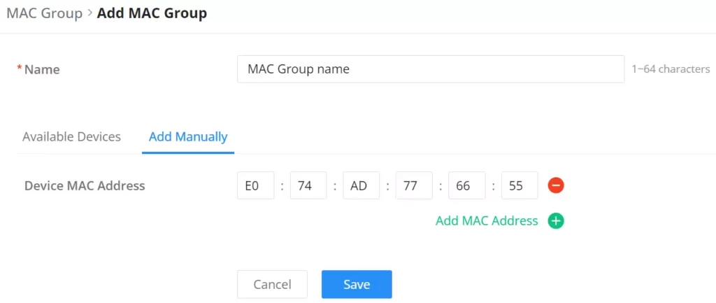
After the MAC Group is created, to take effect, the user needs to apply it, for example, like the SSID:
Navigate to ” Web UI → AP Management → SSIDs“, either click on “Add” button to create new SSID or click on “Edit” icon to edit previously created SSID, scroll down to “Access Security” section then look for “Blocklist Filtering” option and finally select from the list the previously created MAC address, the user can select one or more, or click on “Add” at the bottom of the list to create new one.
Please refer to the figure below:

IP Address Group
The IP Address Group feature allows users to manage groups of IP addresses for applying policies such as security rules, NAT, or firewall settings. Both IPv4 and IPv6 addresses are supported. By grouping addresses, you can manage multiple addresses with ease, improving policy efficiency and reducing errors.
To configure IP Address Groups, follow these steps:
Navigate to Profiles → IP Address Group from the main menu.
IPv4 Address
The IPv4 Address feature lets you add individual IPv4 addresses, subnets, or ranges for use in policies like NAT or firewall settings. Once addresses are added, you can group them for better management.
Steps to add an IPv4 Address:
- Navigate to Profiles → IP Address Group → IPv4 Address.
- Click Add to create a new IPv4 address.
- Enter a Name for the address.
- Select the Type from:
- IP Address
- IP Address/Mask Length
- IP Address Range
- Fill in the relevant details (e.g., IP address, subnet mask, or range).
- Click Save to add the IPv4 address.


IPv4 Address Group
The IPv4 Address Group feature allows you to combine multiple IPv4 addresses into one group, simplifying the application of policies like SNAT or firewall rules.
Steps to create an IPv4 Address Group:
- Navigate to Profiles → IP Address Group → IPv4 Address Group.
- Click Add to create a new IPv4 group.
- Enter a Name for the group.
- Select the IPv4 addresses you wish to include in the group from the list.
- Click Save to create the group.


IPv6 Address
The IPv6 Address feature lets you add IPv6 addresses or networks, which can be used in settings such as firewall rules or NAT configurations.
Steps to add an IPv6 Address:
- Navigate to Profiles → IP Address Group → IPv6 Address.
- Click Add to create a new IPv6 address.
- Enter a Name for the address.
- Select the Type:
- IP Address
- IP Address/Prefix Length
- Fill in the relevant IPv6 address or prefix.
- Click Save to add the IPv6 address.


IPv6 Address Group
The IPv6 Address Group feature allows you to group multiple IPv6 addresses into one group. This makes it easier to apply policies to multiple addresses at once.
Steps to create an IPv6 Address Group:
- Navigate to Profiles → IP Address Group → IPv6 Address Group.
- Click Add to create a new IPv6 group.
- Enter a Name for the group.
- Select the IPv6 addresses to include from the list.
- Click Save to create the group.


IP Address Group – Example
Here’s an example of how to use an IPv4 Address Group in a Source NAT (SNAT) configuration:
- Navigate to Routing → SNAT.
- Click Add to create a new SNAT rule.
- Select the Destination Group as WAN1 (WAN).
- Under Destination Address Type, choose Select IPv4 Address Group.
- Under Destination Address, select the desired IPv4 Address Group from the list.
- Configure other fields such as Destination Port as needed.
- Click Save to apply the rule.

FQDN (Fully Qualified Domain Name)
The FQDN feature allows you to define domain names that can be applied in traffic rules, firewall policies, or other configurations. It can also be paired with specific IP addresses, making it easier to manage domains instead of individual IP addresses.
You can create individual FQDN Addresses or group multiple FQDN addresses into an FQDN Address Group for easier management and application in rules.
FQDN – Address
An FQDN Address is a domain name entry that can optionally be associated with up to eight IP addresses. This is useful for applying domain-based traffic filtering or rules.
To create an FQDN Address:
- Navigate to: Profiles → FQDN → Address
- Enter the following:
- Name: Name of the FQDN address (e.g., “Grandstream”).
- FQDN: Enter the domain (e.g.,
*.grandstream.com). Wildcards can be used to match subdomains. - Manually added IPs (optional): Add up to 8 IP addresses to be associated with the FQDN.
- Click Save to add the FQDN entry.


FQDN – Address Group
FQDN Address Groups allow you to group several FQDN addresses, which simplifies applying multiple FQDNs within traffic rules.
To create an FQDN Address Group:
- Navigate to: Profiles → FQDN → Address Group
- Provide a Name for the group.
- Select the FQDN addresses to be included in the group.
- Click Save to create the group.


FQDN – Example
Here is an example of applying an FQDN Address Group in a firewall rule. This will show how to use domain-based filtering within your network.
Example: Applying FQDN Address Group in a Traffic Rule
- Navigate to: Firewall → Traffic Rules → Add Inbound Rule.
- For Source Address Type, select FQDN Address Group.
- Select the previously created FQDN Address Group (e.g., “FQDN Address Group”).
- Configure any other parameters as needed and click Save.

RADIUS
RADIUS is a networking protocol that provides centralized authentication, authorization, and accounting for users or devices connecting to a network. In the GCC device, the RADIUS feature allows network administrators to integrate external RADIUS servers for handling network access.
To create a RADIUS profile:
- Navigate to: Profiles → RADIUS → Add.
- Enter the RADIUS server details:
- Authentication Server: Enter the server address and port for authentication (default port is 1812).
- RADIUS Accounting Server: Enter the server address and port for accounting purposes (default port is 1813).
- RADIUS NAS ID: Input the NAS ID (Network Access Server ID).
- Attempt Limit: Specify the number of attempts before the server denies access.
- RADIUS Retry Timeout: Set the time to wait before retrying a connection to the server (in seconds).
- Accounting Update Interval: Set the interval at which accounting updates will be sent (in seconds).
- Save the profile.


RADIUS – Example
Applying the RADIUS Profile to a Wi-Fi SSID:
- Navigate to: AP Management → SSIDs → Add.
- In the Access Security section, configure the following:
- Security Mode: Select WPA2.
- WPA Key Mode: Select PPSK with RADIUS or another option based on the required encryption method.
- RADIUS Profile: Select the previously created RADIUS Profile from the dropdown list.
- Save the settings.

Schedule
GCC devices allow the user to create a schedule, either weekly based or an absolute date/time (specific date and an interval), then these schedules can be assigned to various services on GCC devices: Upgrade, SSID, Bandwidth limit, Policy route, and reboot.
To create a schedule, navigate to Profiles → Schedule, then click the “Create Schedule” button as shown below:
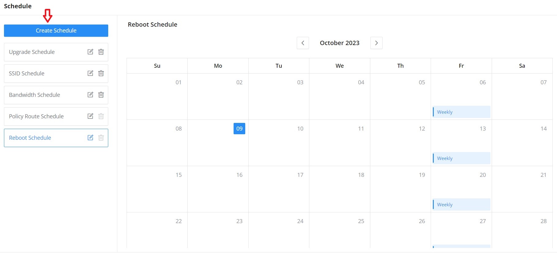
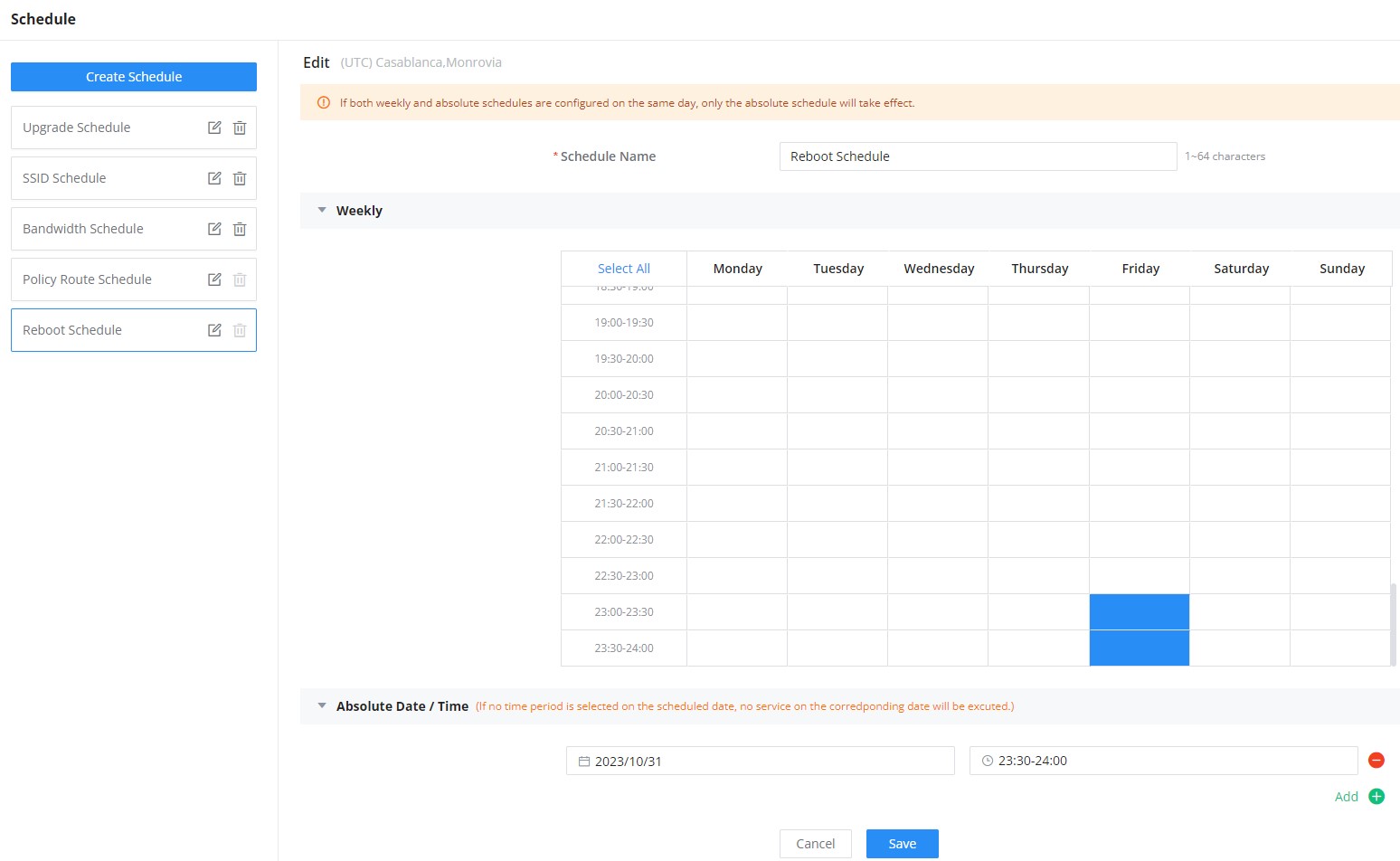
Certificates
CA Certificates
In this section, the user can create a CA certificate. This certificate will authenticate the user when connected to the VPN server created on the router. This authentication will ensure that no identity is being usurped and that the data exchanged remains confidential. To create a certificate, please access the web GUI of the router and go to Profiles → Certificates → CA Certificates, then click “Add” and fill in the necessary information.
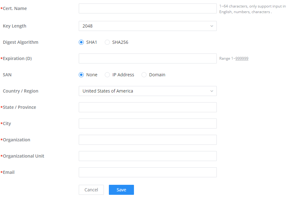
Cert. Name | Enter the Certificate name for the CA. Note: It could be any name to identify this certificate. Example: “CATest”. |
Key Length | Choose the key length for generating the CA certificate. The following values are available:
|
Digest Algorithm | Choose the digest algorithm:
Note: Hash is a one-way function, it cannot be decrypted back. |
Expiration (D) | Enter the validity date for the CA certificate in days. The valid range is 1~999999.. |
Country / Region | Select a country code from the dropdown list. Example: “United Stated of America”. |
State / Province | Enter a state name or province. Example: “Casablanca”. |
City | Enter a city name. Example: “SanBern”. |
Organization | Enter the organization’s name. Example: “GS”. |
Organizational Unit | This field is the name of the department or organization unit making the request. Example: “GS Sales”. |
Enter an email address. Example: “EMEAregion@grandstream.com” |
Add CA Certificate
Certificate
In this section, the user can create a server or a client certificate. To create a certificate please access the web UI of the router, then navigate to Profiles → Certificates → Add Certificate, click “Add”, then enter the necessary information regarding the certificate.
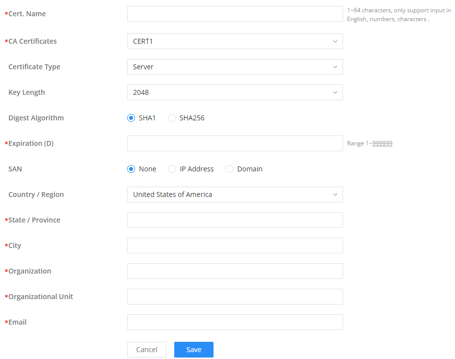
Cert. Name | Enter the certificate’s name. |
Key Length | Choose the key length for generating the CA certificate.The following values are available:
|
Digest Algorithm | Select the digest algorithm.
Note: Hash is a one-way function, it cannot be decrypted back. |
Expiration (D) | Select the duration of validity of the certificate. The number entered represents the days that have to elapse before the certificate is considered as expired. The valid range is 1 – 999999. |
SAN | Enter the address IP or the domain name of the SAN (Subject Alternate Name). |
Country / Region | Select a country from the dropdown list of countries. Example: “United States of America”. |
State / Province | Enter a state name or a province. Example: California |
City | Enter a city name. Example: “San Diego” |
Organization | Enter the organization’s name. Example: “GS”. |
Organization Unit | This field is the name of the department or organization unit making the request. Example: “GS Sales”. |
Enter an email address. Example: “EMEAregion@grandstream.com” |
Add Certificate
Certificates Backup and Restore
To backup the created certificates, first select all the desired certificates, then click the “Backup” button and enter a password to protect it as shown below:
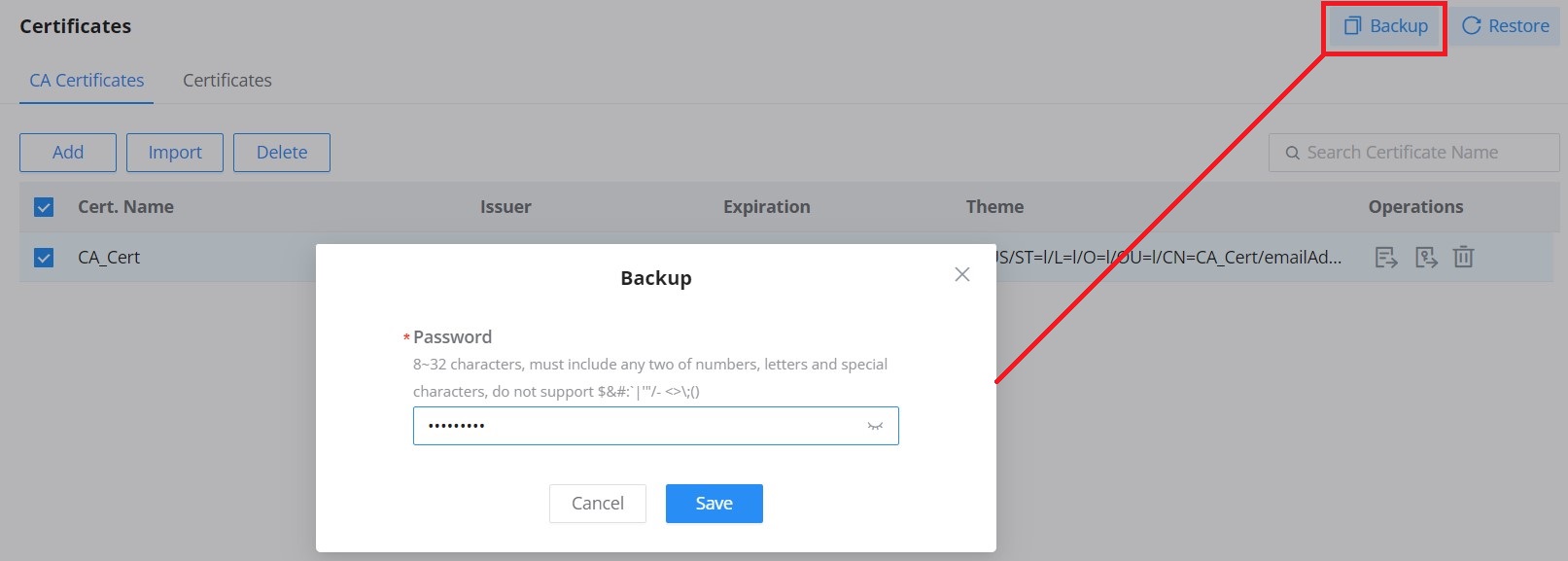
To restore a certificate, click the “Restore” button, then upload the file and enter the password.
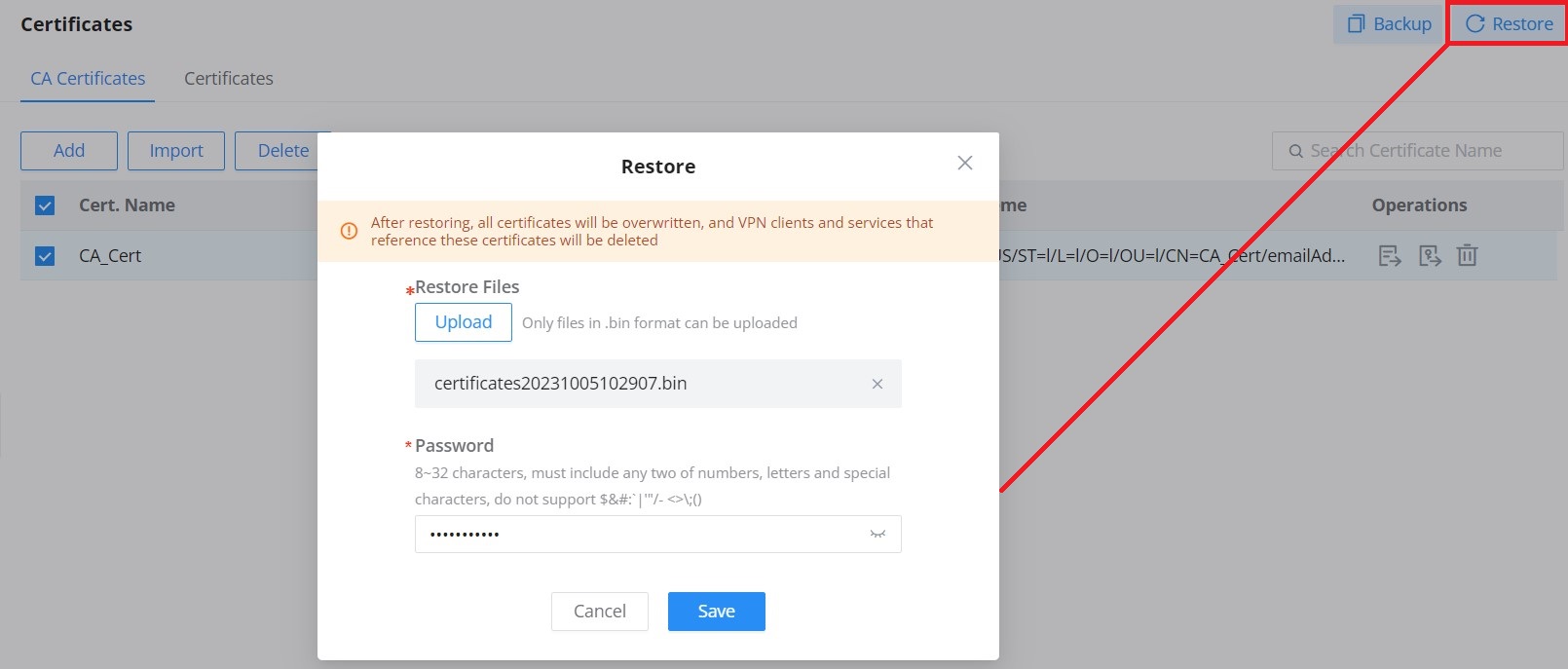
PERMISSION MANAGEMENT
Permission Management allows the administrator to create multiple roles with different permissions, it allows creating roles with permissions of reading, or reading and writing privileges which allow monitoring, or monitoring and changing the settings on the Networking module, respectively.
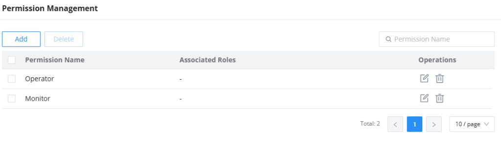
Click on  button to add a new permission category. Enter the permission name, then select the functions, you can select to allow read, or read and write permissions.
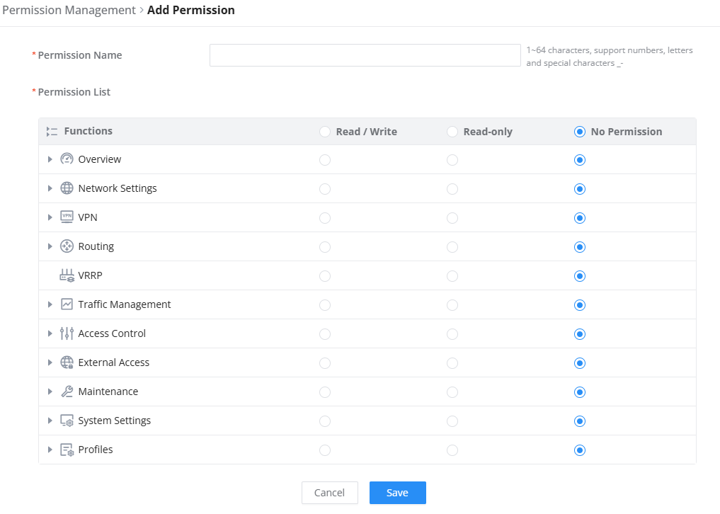
CHANGE LOG
This section documents significant changes from previous versions of user manuals for GCC601x. Only major new features of the networking module or major document updates are listed here. Minor updates for corrections or editing are not documented here.
Firmware version 1.0.7.59 (PBX version 1.0.27.94)
- Added Permission Management section [PERMISSION MANAGEMENT]
Firmware version 1.0.7.59 (PBX version 1.0.27.94)
- Added support for Bridge mode [Bonjour Gateway]
Firmware version 1.0.7.48 (PBX version 1.0.27.90)
- Added support for GDMS new IPsec option “Add Router LAN address”, which will allow the router to use its own LAN address to configure local subnet for VPN.
- Added support for [USB 4G/5G dongle].
Firmware version 1.0.7.46 (PBX version 1.0.27.90)
- No major changes.
Firmware version 1.0.7.44 (PBX version 1.0.27.89)
- Added the “Port Name” field in “Port Configuration” and added the adaptive option for optical port rate and duplex. [Port Configuration]
- Added VLAN option under Static IP. [Static IP Binding]
- Added ZeroTier option to VPN Setup Wizard. [Setup Wizard]
- Added ZeroTier configuration interface under VPN. [ZeroTier VPN]
- Added RADIUS Authentication mode and Certificate + RADIUS Authentication to OpenVPN server. [OpenVPN® Server]
- Added “Custom” option to DDNS service provider list, allowing manual configuration of third-party providers. [DDNS]
- Added support for microSD storage devices. [File Sharing]
- Updated QoS bandwidth limits for Maximum Uplink/Downlink Bandwidth to 1–2560 Mbps. [QoS]
- Updated Traffic Management – Bandwidth Limit for Maximum Uplink/Downlink Bandwidth to 1–2560 Mbps. [Bandwidth Limit]
Firmware version 1.0.7.10 (PBX version 1.0.27.47)
- No major changes.
Firmware version 1.0.7.5
- Added Bridge Mode configuration under Network Settings → WAN to support VLAN-to-port mapping with priority settings for multi-service deployments (e.g., Triple Play). [Bridge Mode]
- Optimized Static IP Binding configuration under Network Settings → LAN for a simplified user experience by removing VLAN selection and streamlining the IP assignment process. [Static IP Binding]
- Added VPN Setup Wizard for simplified VPN tunnel configuration. [VPN Setup Wizard]
- Optimized configuration interface and added “User Manual” link for WireGuard®, IPSec, OpenVPN®, PPTP, and L2TP. [VPN]
- Added “Remote Clients” table in WireGuard® configuration. [WireGuard®]
- Added support for domain names in WireGuard® Endpoint address field. [WireGuard®]
- Added IPSec Encryption option to L2TP server configuration. [L2TP]
- Added support for exporting .ovpn file in OpenVPN® Client configuration. [Remote Users]
- Added Routing Table page. [Routing Table]
- Added OSPF, RIP, and BGP protocols. [Routing]
- Added IP-based traffic statistics. [Traffic Management]
- Added IP Source and Update Interval (Min) settings to DDNS configuration. [DDNS]
- Added Clone feature to Port Forwarding rules for quick duplication. [Port Forwarding]
- Added input restrictions to TR-069 ACS Username and Password. [TR-069]
- Relocated Ping/Traceroute/NSlookup to Maintenance → Network Tools, and Core File to Home → Logs & Diagnostics. [System Diagnostics]
- Added features of NSlookup and Wake on LAN under [Network Tools]
- Added a feature of Local Logs download under Syslog. [Syslog]
- Added Email Settings page. [System Settings]
- Added Profiles section with support for MAC Group, IP Address Group, FQDN, RADIUS, and Certificates. [Profiles]
Firmware version 1.0.5.11
- No major changes.
Firmware version 1.0.5.6
- Added support for the Balancing strategy in Policy Routes Settings. [Balancing Strategy]
- Added Support for the VRRP protocol. [VRRP]
- Added option to preserve VPN configuration when the VPN is disabled. [VPN]
- Added Speed Test for the GCC from the GDMS Networking. [WAN]
- Set the maximum IPsec tunnels to be created to 64 tunnels. [IPSec]
Firmware version 1.0.3.6
- No major changes.
Firmware version 1.0.3.5
- Added the option to allow multiple WANs to share the same VLAN ID. [WAN]
- Added the requirement that when IPv6 is enabled on the WAN, the minimum MTU must be 1280. [WAN]
- Added WAN port MAC address configuration. [WAN]
- Added the requirement that not all LAN ports can be disabled [Port Configuration]
- Added the assurance that disabling the WAN will not delete dependent configurations. [WAN]
- Added support for exporting .pem format certificates. [Certificates Import and Export]
- Added a black hole option for the outgoing interface. [Static Routes]
- Added PBX service [VoIP Settings]
- Added support for core files batch deletion [Core files]
- Added support for storage options under packet capture [Capture]
- Added alarm Notification Settings and Email Notification Settings for takeover/un-takeover, switch online and offline alarms [Alerts & Notifications]
Firmware version 1.0.1.34
- No major changes.
Firmware version 1.0.1.32
- This is the initial version for GCC6010W and GCC6011.
Firmware version 1.0.1.10
- Disabled Check/Download New Firmware at Boot up by default. [Upgrade]
Firmware version 1.0.1.8
- This is the initial version.