
WELCOME
Thank you for using the Grandstream GWN Management Platform.
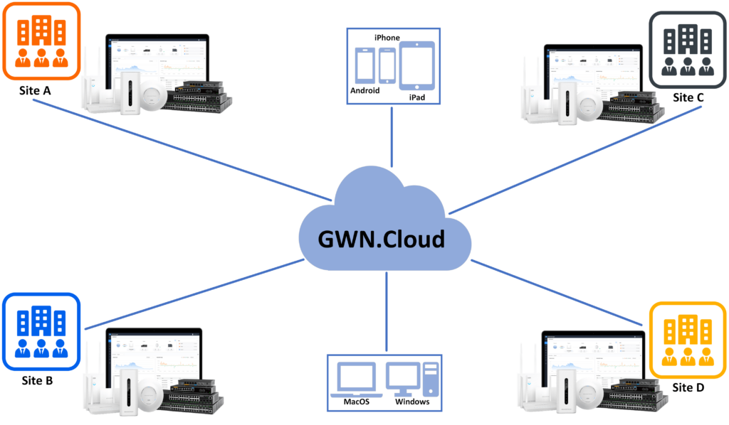
GWN Management Platforms are enterprise-grade Wi-Fi network management platforms that offer centralized, streamlined network management and monitoring. This includes GWN.Cloud, the cloud-based platform, and the GWN Manager which is a Linux-based platform and GWN App for Android® and iOS®. It allows businesses to deploy a secure Wi-Fi network in seconds and manage these networks across multiple locations through a web user interface. Users can keep an eye on the network’s performance with real-time monitoring, alerts, statistics, and reports that can be viewed using a web browser or a mobile application. Support unified management for different types of Grandstream devices (Routers, Switches, APs and GCC devices) in one network and SDN design, to make the network management more simple, and user-friendly.
PRODUCT OVERVIEW
Features Highlights
GWN.Cloud |
|
GWN Manager |
|
Shared |
|
Features Highlights
Specifications
Function |
|
Security and Authentication |
|
Enterprise Features |
|
Supported Devices |
|
Captive Portals |
|
Centralized Management |
|
Reporting and Monitoring |
|
Maintenance |
|
Languages | English, Chinese, Spanish, German, Portuguese, French and more. |
GWN Management Platform specifications
GETTING TO KNOW GWN MANAGEMENT PLATFORM
GWN.Cloud
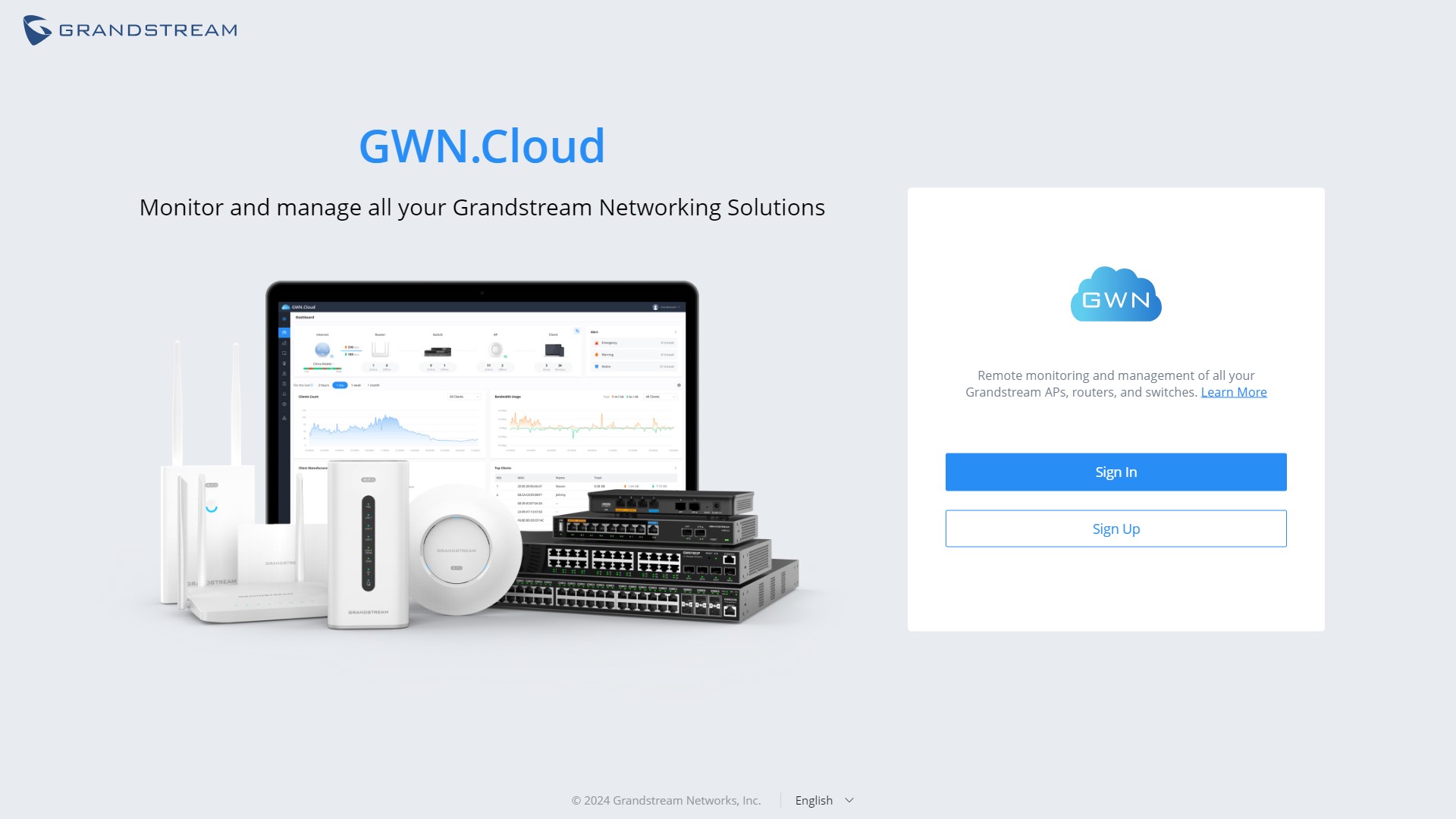
GWN.Cloud is a cloud-based platform used to manage and monitor Grandstream devices (GWN Access Points, GWN Routers, GWN Switches and GCC devices) wherever they are as long as they are connected to the internet. The platform can be accessed using the following link: https://www.gwn.cloud. It provides an easy and intuitive web-based configuration interface as well as an Android® and iOS® App.
Sign up to GWN.Cloud
When accessing GWN.Cloud for the first time, users are required to sign up. The following screen will be displayed:
- Click on Sign up to go to the sign-up screen, then enter the required information.
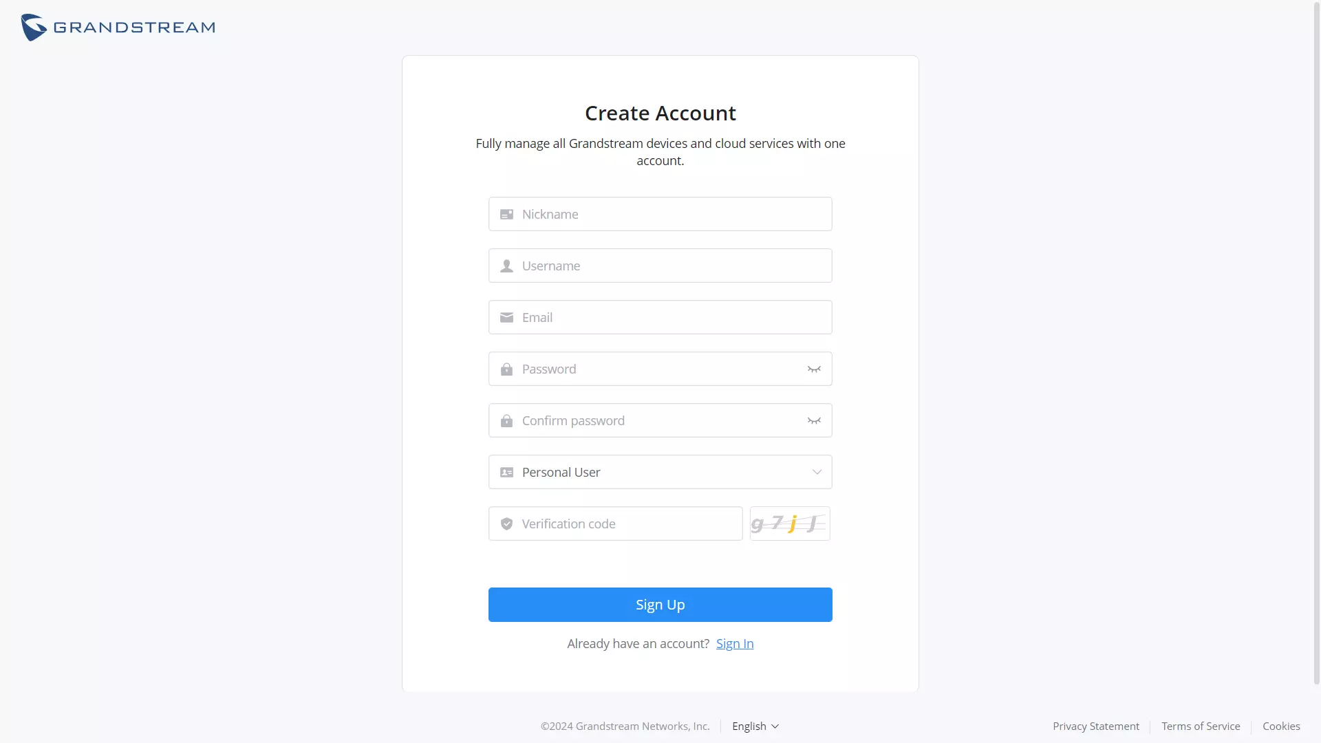
Nickname | Specify a nickname of this account. |
Username | Specify a username for this account. |
Enter the email address. | |
Password | Specify a password for the account Note: 8-16 characters, must be a combination of numbers, letters, and special characters. |
Confirm password | Re-enter the password again. |
User type | Select from the drop-down list the type of user:
|
Company Name | Enter the company name if the type of user is set to Enterprise, Server provider, Channel reseller, System integrator. |
Verification code | Copy the verification from the Captcha. |
GWN.Cloud Sign-up Settings
2. Once you create an account, you can access your GWN.Cloud page for the first time and the following page will be displayed:
Region settings
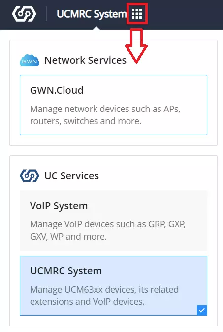
To switch to network services (GWN.Cloud) when the user was in another service such as (VoIP system or UCMRC system), on the top left of the web page, click on the dots icon and select GWN.Cloud under Network Services as shown below:
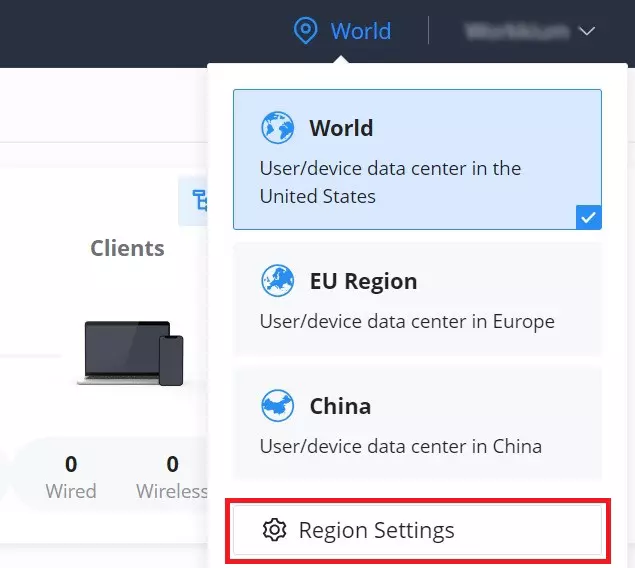
Region settings allows the users to enable different regions (data center). To enable or delete a region, on the top right of the page click on the location icon → region settings as shown below:
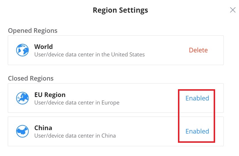
The users and devices data is stored in the enabled regions, to delete a region click on “Delete“, and to enable a region click on “Enabled“.
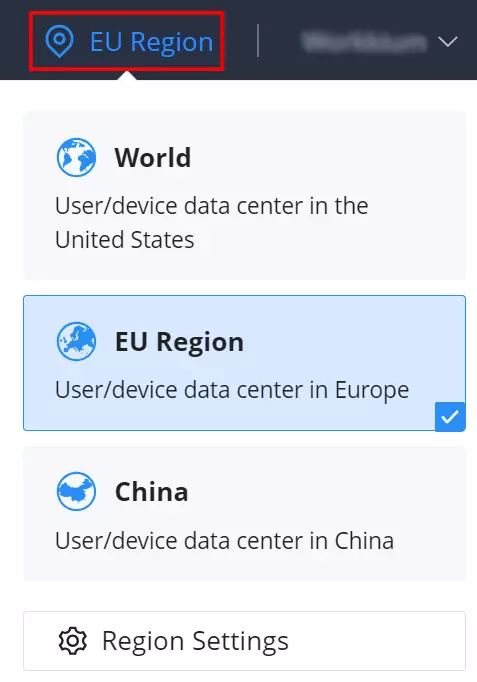
To start using the enabled region to store users/devices data, make sure it’s selected on the main page as shown below:
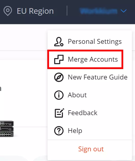
Merge Accounts
Merge accounts feature allows users to merge different account with different services and regions into one single base account. On the main page of GWN.Cloud, top right corner of the page, click on the account name then select Merge Accounts as shown below:
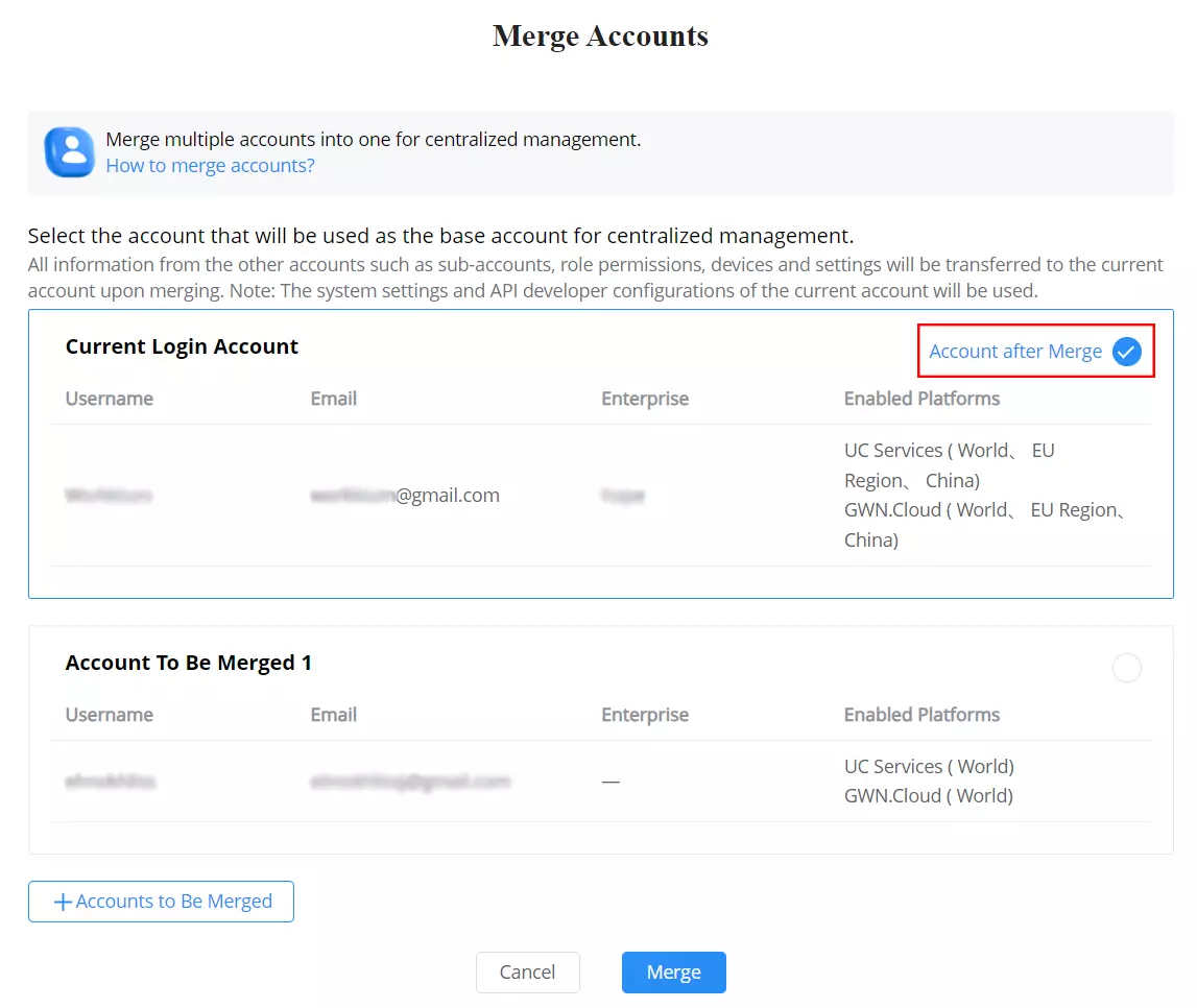
Click on “+Accounts to Be Merged” button to add more account, then select the base account that will be used for centralized management.
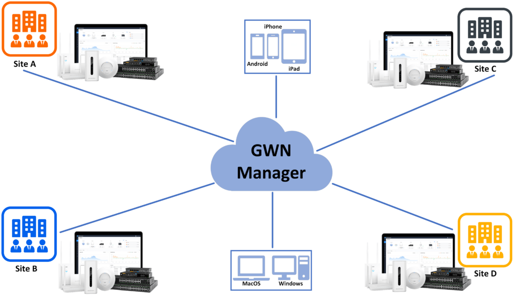
GWN Manager
GWN Manager is an On-premise Grandstream devices Controller used to manage and monitor network devices including GWN Access points, GWN Routers, GWN Switches and GCC devices on your network.
GWN Manager Harware Requirements
Sofware Requirements | Hardware requirements |
Operation System:
| For up to 200 devices and 2 000 clients:
|
For up to 3 000 devices and 30 000 clients:
| |
For up to 10 000 devices and 200 000 clients:
| |
For up to 30 000 devices and 600 000 clients:
| |
For up to 50 000 devices and 1 000 000 clients:
|
GWN Manager hardware requirements
Installation
To install GWN Manager please visit the links below:
GWN Manager – Quick Installation Guide
GWN Manager – Deploying a Virtual Machine from an OVA file
First Use
The GWN Manager provides an easy and intuitive Web UI to manage and monitor GWN network devices, it provides users access to all GWN settings, without any additional on-premise infrastructure.
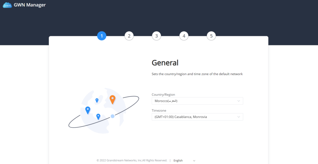
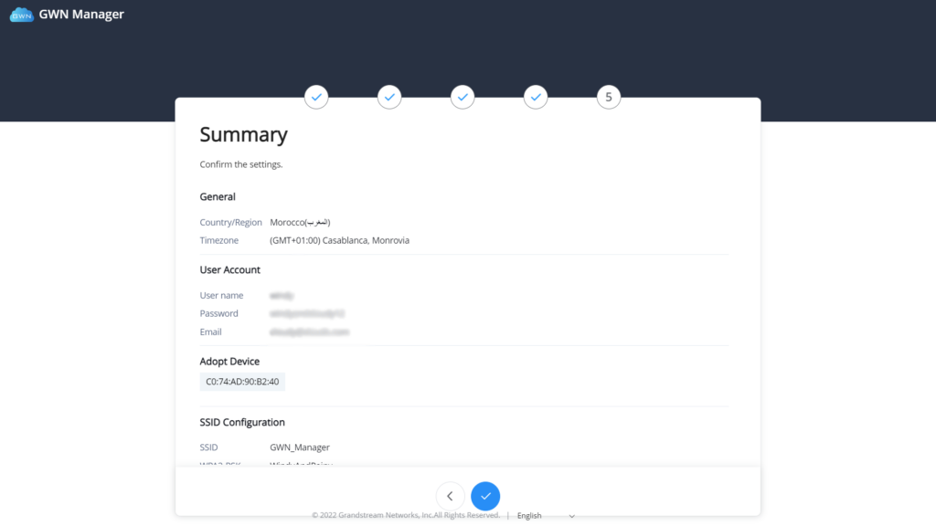
On first use, users need to fill in additional information following the GWN Manager Wizard:
General | Specify the country/region and time zone for the default network. Note: these parameters can be automatically detected by the system. |
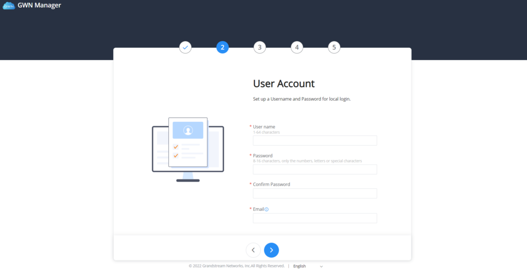
User Account | Set up a username, password and email for local login. |
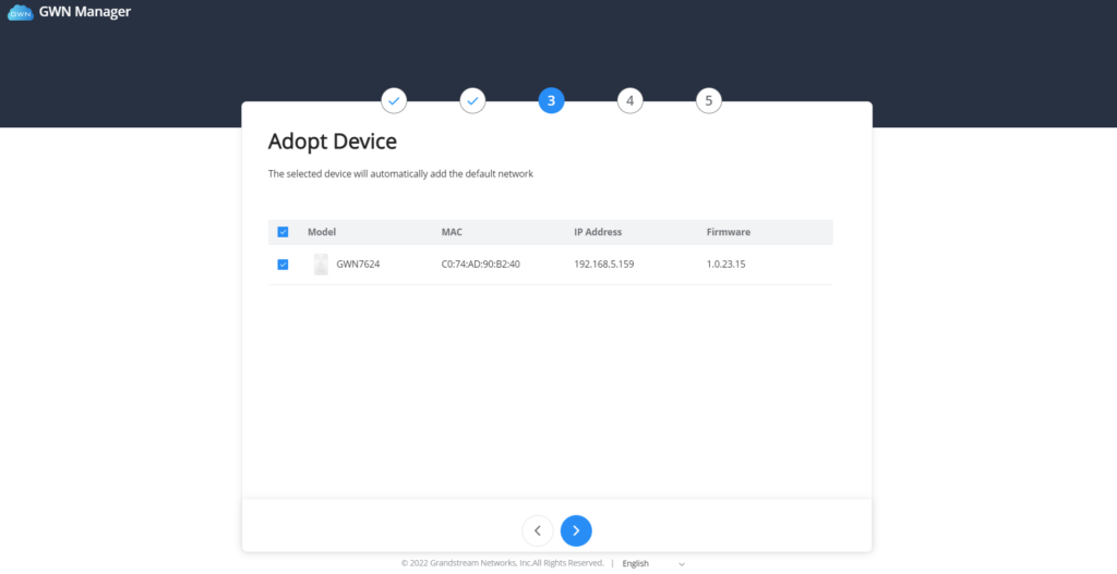
Adopt Device | Select the GWN devices to be adopted by the default network. Note: Access points, Routers available on the same LAN will be detected automatically. |
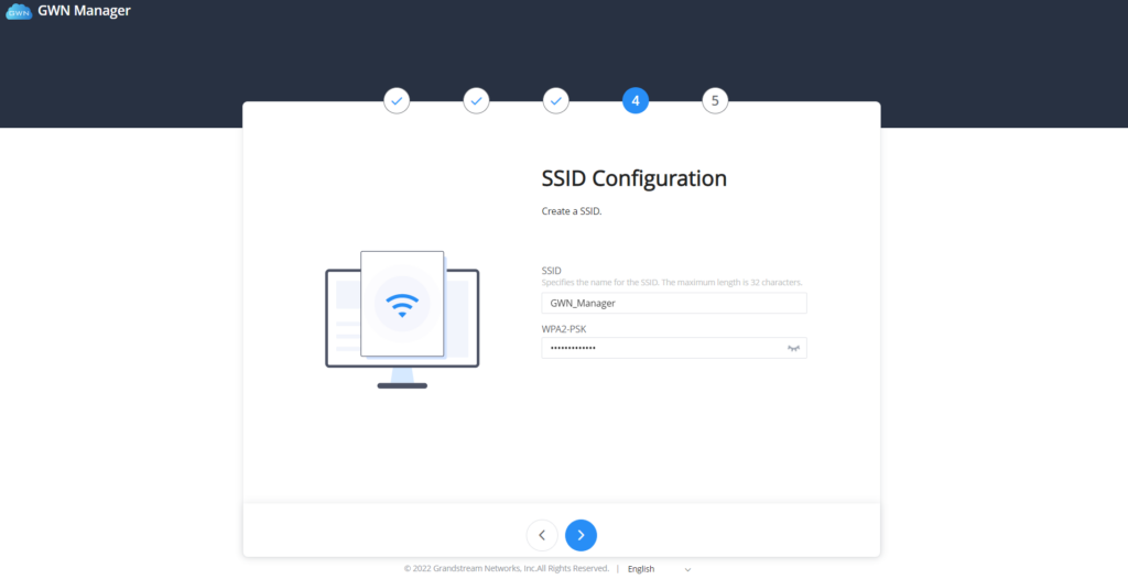
SSID Configuration | Create an SSID to be used by the default network for the first time. Note: this SSID can be modified later. |
Summary | Review all the previous settings |
GWN Manager setup wizard
Sign up to GWN Manager
Enter the previously configured user credentials to access the GWN Manager GUI:
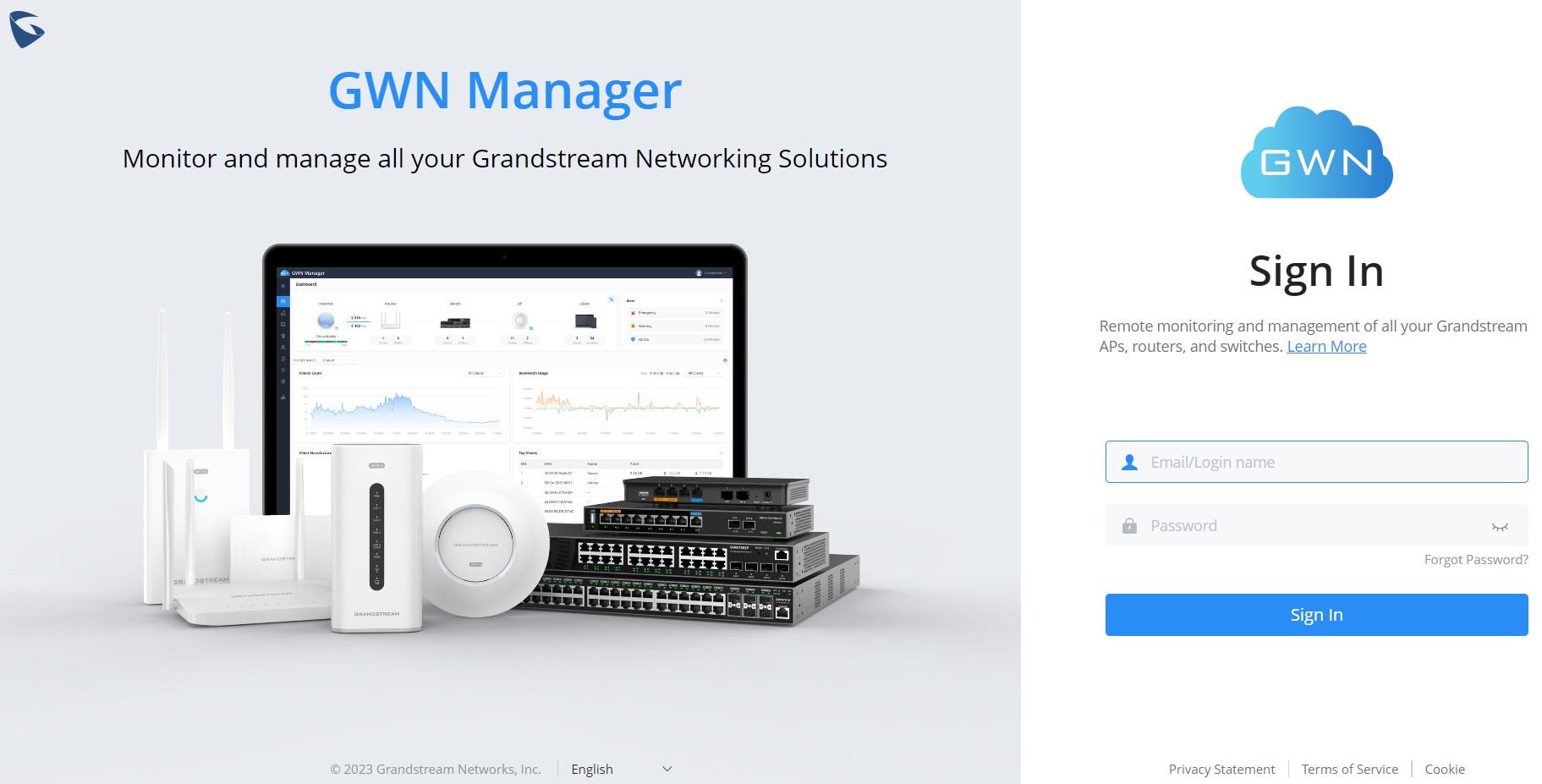
The following page will be displayed:
Personal Settings
To edit the personal settings of the currently log in account, click on the name account from the top right corner → Click on Personal Settings a new page displaying the account details will be displayed, refer to the figure below:
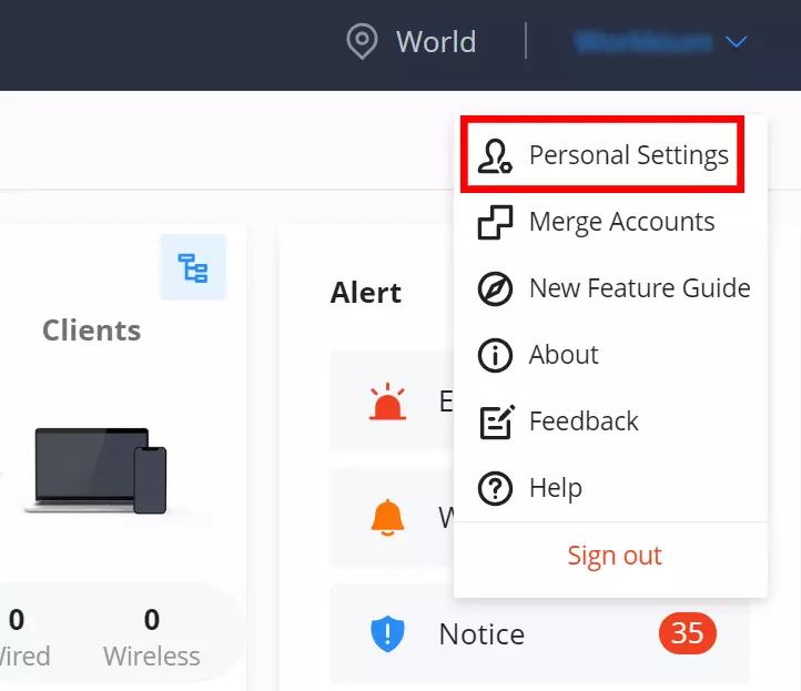
To modify a field click on “Modify” text, refer to the figures and table below:
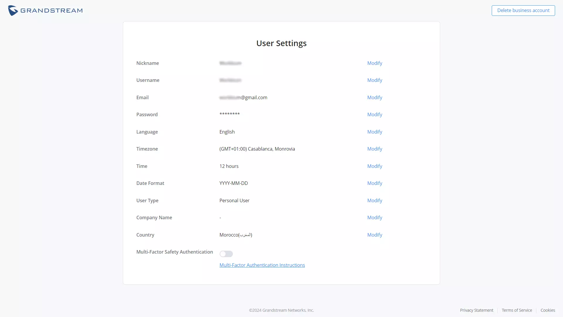
Nickname | Modifies the user nickname |
Username | Modifies the username |
Modifies the Email address | |
Password | Changes the password |
Language | Select the web UI language from the drop-down list |
Timezone | Select the timezone from the drop-down list |
Time | Select the time format: 12 hours or 24 hours |
Date Format | Select the date format from the drop-down list |
User Type | Select the user type from the drop-down list |
Company Name | Specifies the company name |
Country | Select the country from the drop-down list |
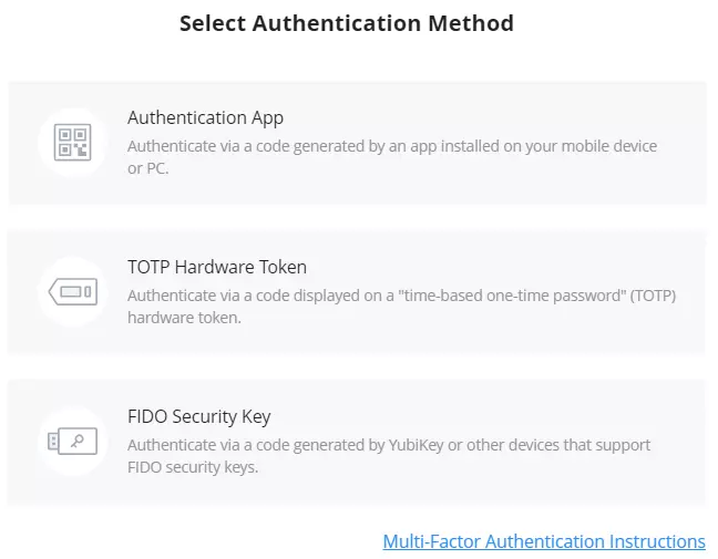
Multi-Factor Safey Authentication | Toggle ON/OFF the Multi-Factor authentication Note: for more details, visit Multi-Factor Authentication |
Personal Settings
Feedback
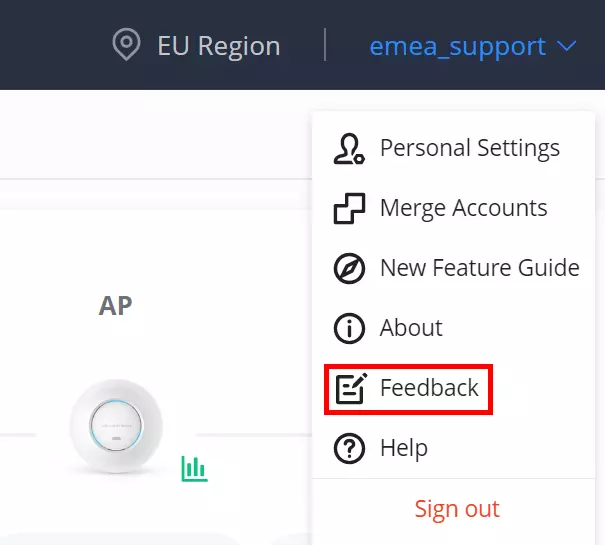
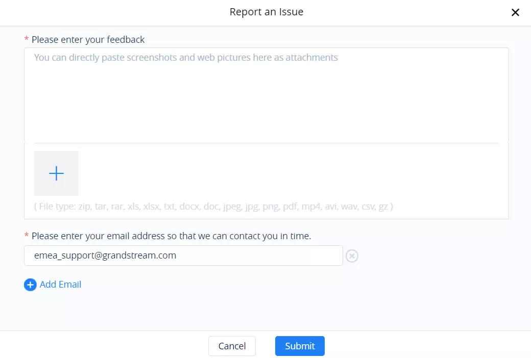
If the users have an issue/bug to report or need help about configurations or a general feedback, on the top right corner of the page, click on the account username then click on “Feedback” to send a feedback.
Then, select what type of feedback:
- I have an issue/bug to report and need a solution (forwards the users to Grandstream helpdesk)
- I need help on my configurations (forwards the users to Grandstream helpdesk)
- Feedback.
- Other.
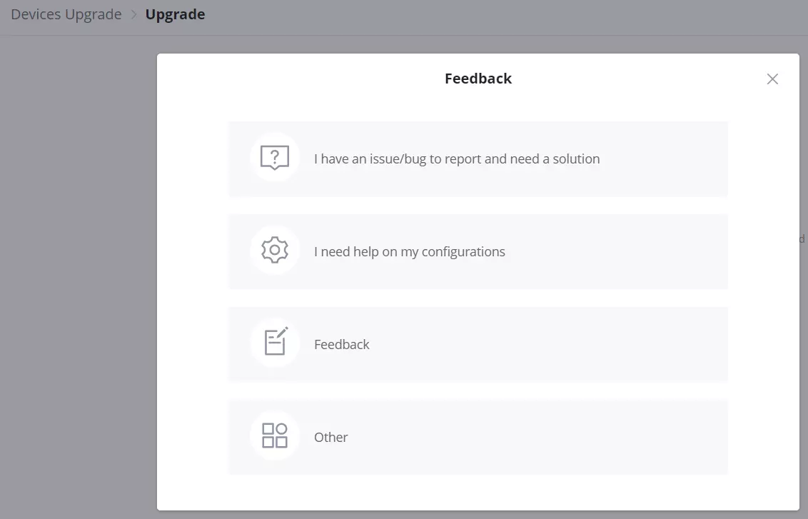
If Feedback or Other is selected, this page will be shown for users to specify the issue/bug/feedback with attachments (e.g. syslog) and emails for contact.
GETTING STARTED WITH GWN MANAGEMENT PLATFORM
The GWN Management Platforms provide an easy and intuitive Web UI or mobile app (both Android® & iOS® versions) to manage and monitor Grandstream devices (Access points, Routers, Switches and GCC devices), it provides users access to all devices’ settings, without any additional on-premise infrastructure.
Add a Device to GWN Cloud
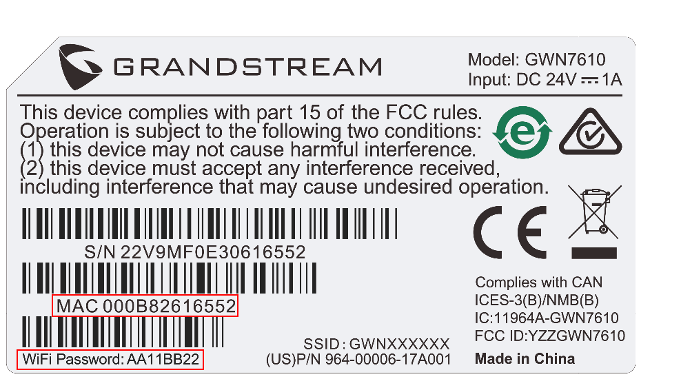
To add a device to GWN.Cloud, the administrator needs two pieces of information:
- MAC address of the device.
- Password in the back of the unit.
There are 3 methods to adddevices to the cloud:
- Method 1: Adding a New Device Manually
- Method 2: Adding a New device using the GWN Application
- Method 3: Transfer APs control from Local Master (only for GWN Access points)
Method 1: Add a new device manually
- Locate the MAC address on the MAC tag of the unit, which is on the device, or the package.
- Locate the Password.
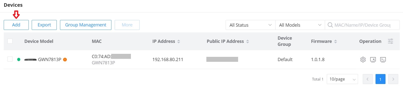
3. Navigate to Devices and click on the “Add” button.
4. Select a name for the device then enter the MAC address and Password, the user has also the option to add equipment remarks to easily identify the devices when added to the GWN.Cloud or GWN Manager. Also, there is the option to select a device from the Inventory (previously claimed). Please, check the figures below:
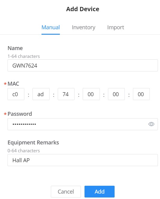
If the device is a router, the users will have to option to automatically synchronize router local WAN configurations to GWN.Cloud and also assign the SSIDs that are already in the network to the newly added router.
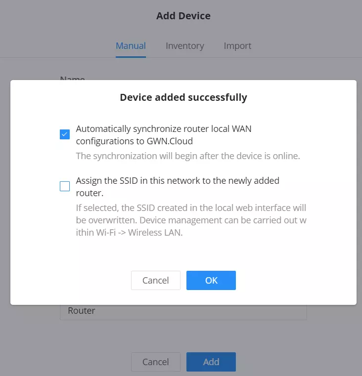
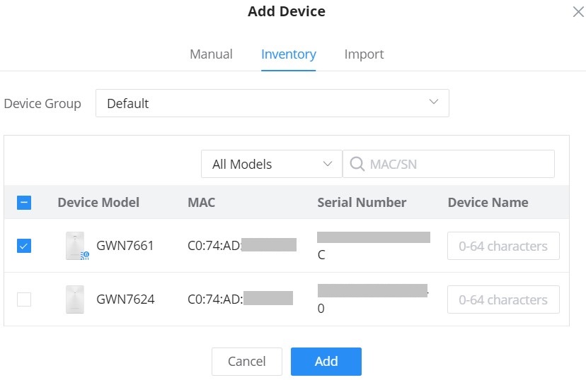
5. Click on the “Add” button, the device will be added automatically to your Cloud account and you will be able to monitor/manage it.
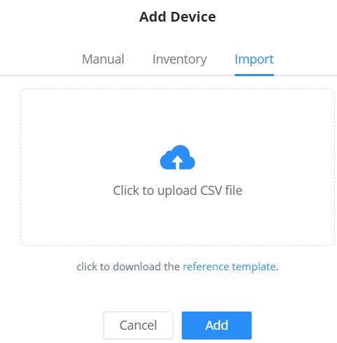
Bulk-add devices using CSV file import
Another option for bulk-add devices is to use CSV file upload.
After clicking on “Add” under the menu Devices, click on the Import Tab and click on the “Add” button to select a CSV file.
Method 2: Add a new device using GWN.Cloud Application
An easy way to add a new device to your GWN.Cloud is to use GWN.Cloud Application.
The operation is done by scanning the barcode from the device’s sticker.
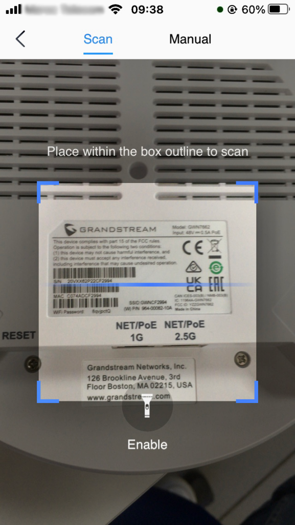
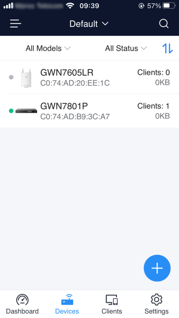
Once added, the list of devices will be displayed on GWN.Cloud interface.
Method 3: Transfer from Local Master
In the case where a local master is managing the Access points. Another method to add devices (Access points slaves) to the cloud is by transferring them to the cloud from the local Master. Follow these steps to achieve this:
- Access the web UI of the local master and go to Access Points.
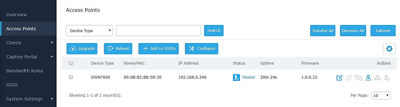
2. Press ![]() button. A new window will display the “Transferable devices” list as shown below.
button. A new window will display the “Transferable devices” list as shown below.
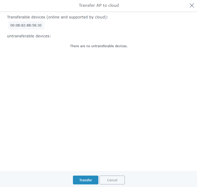
3. Press ![]() button. The web browser will redirect to GWN.Cloud login page.
button. The web browser will redirect to GWN.Cloud login page.
4. Once logged in to the cloud, the configuration page “Select Network” will be displayed:
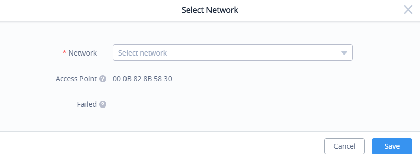
- Access Point: Shows the MAC address of the passed check device.
- Failed: Shows the MAC address of the authentication failed or added.
5. Select Network from the drop-down list to which the AP will be assigned.
6. Press the Save button to confirm.
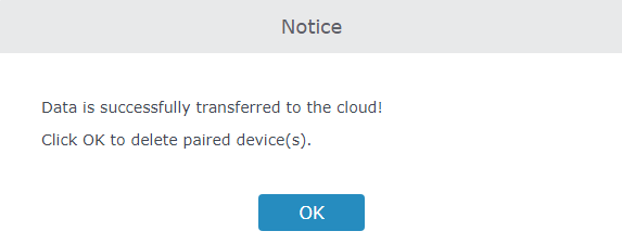
7. Once added to the cloud, Master AP web UI will display following successful notice.
Adopt a Device to GWN Manager
To add devices (router, switch, access point, GCC) to the GWN manager:
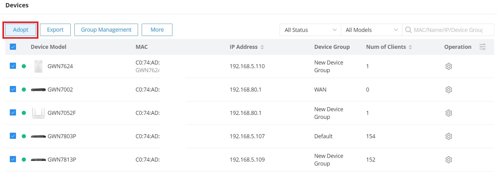
- Navigate to GWN Manager Web UI → Devices
- Click on the “Adopt” button.
3. If GWN Manager connects to the same local subnet as Grandstream devices, it can discover the devices automatically via layer 2 broadcast. GWN devices accept DHCP option 224 encapsulated in option 43 to direct the controller. An example of DHCP option 43 configuration would be:
224(type)18(length)172.16.1.124:10014(value) translated into Hex as e0123137322e31362e312e3132343a3130303134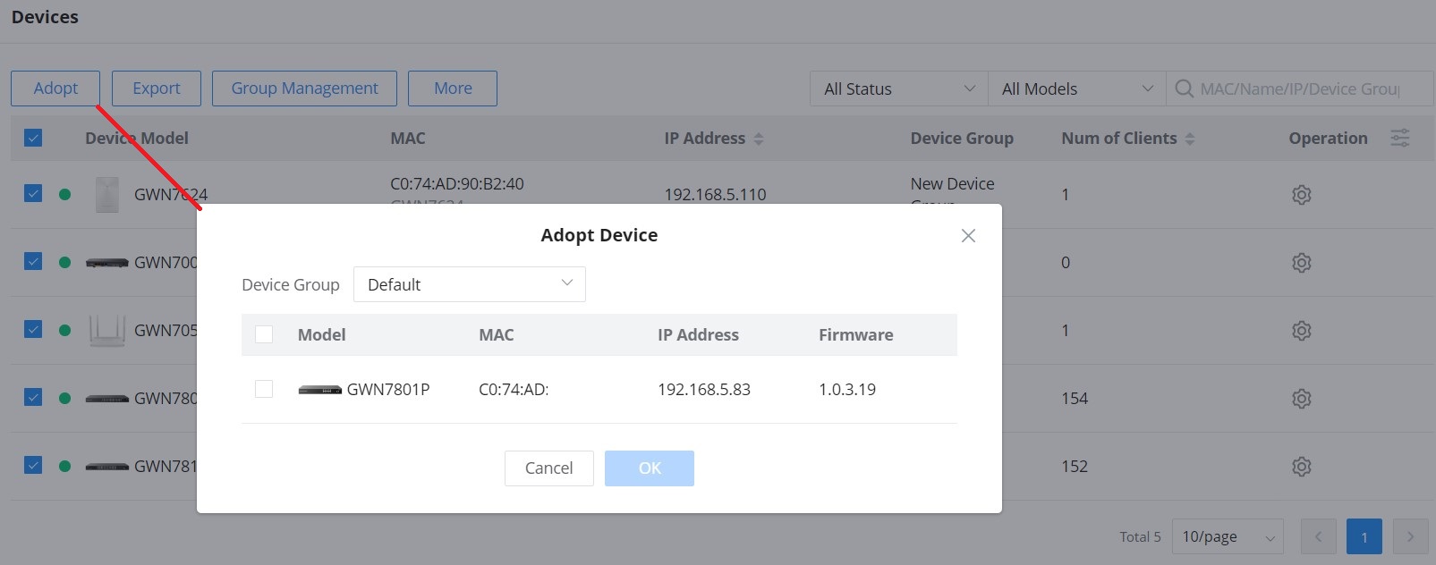
4. Select a device by checking the box on its left. Or select all by checking the top box. Then click the “OK” button.
When adopting a GWN router or a switch, the user will be prompted to enter the router/switch’s current administrator password, please refer to the screenshots below.

When clicking “OK”, the user will be prompted to enter the current password of the administrator account of the device to finish adopting the device.

Adopting devices manually
To manually configure the manager address and port on a GWN device, enable Manager Settings, fill in the Manager Address and Port, and finally click on the “Save” button. For each GWN device (AP, Router, or Switch), please check the steps below:
You can log into the WebUI of a slave AP or an unpaired AP to set the Manager address and port.
For GWN APs, please log in to the GWN AP in slave mode, then navigate to GWN AP Web UI → System → Manager Settings.
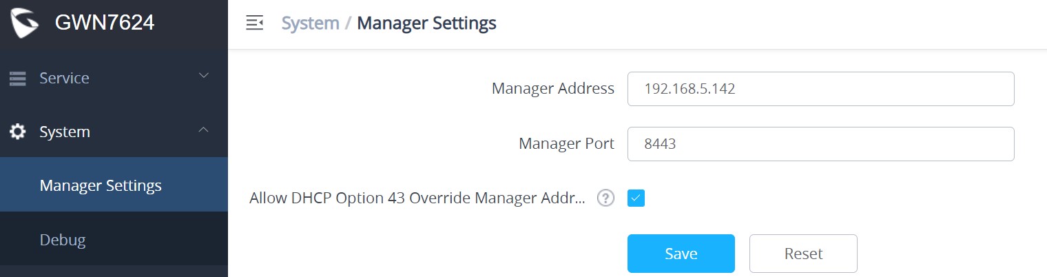
For GWN routers, please navigate to GWN Router Web UI → System Settings → Basic Settings page → Manager Server Settings tab.
For GWN switches, please navigate to GWN Switch Web UI → System → Access Control page → Manager Settings tab.
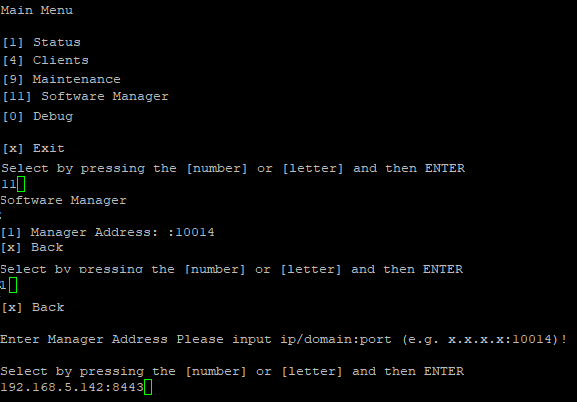
It’s also possible to SSH a slave AP and use the GWN menu to set the Manager address and port (8443).
NETWORKS
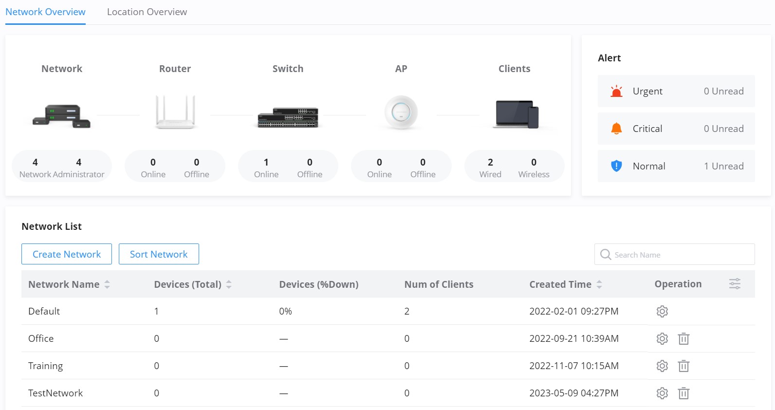
The network page provides information regarding all the network groups created under your account, once the administrator selects one network all the other configuration pages will change to reflect the information related to the selected network.
Create a new Network
To create a new Network:
- Navigate to GWN Manager Web UI → Organization → Overview → Network Overview Tab, all the previously created networks will be displayed here.
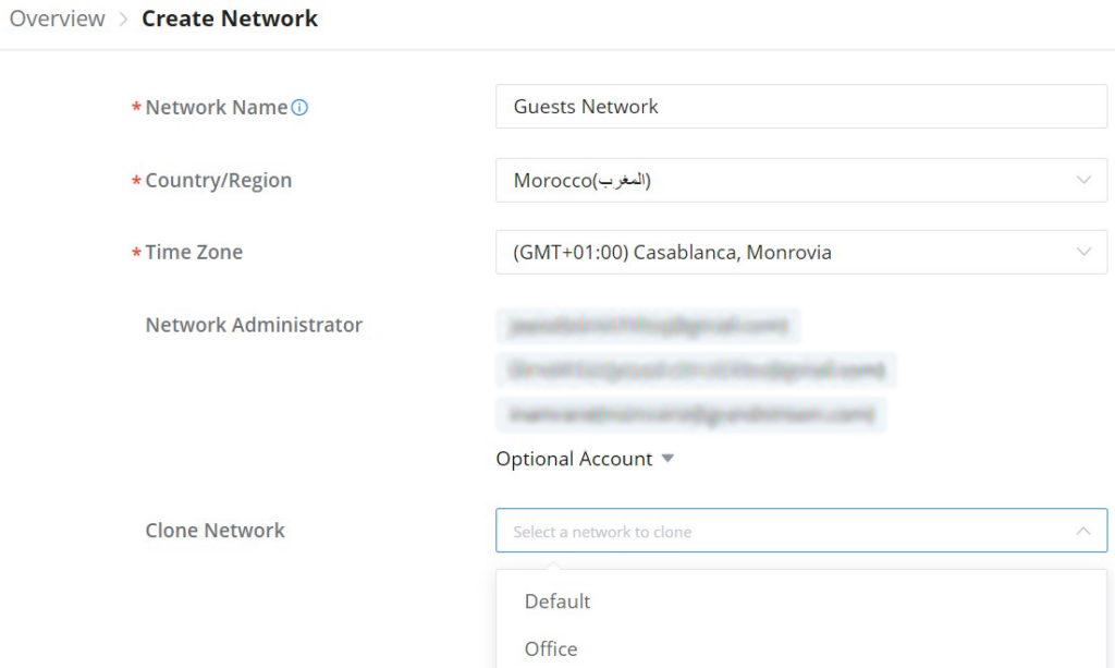
- Click on the “Create Network” button and enter the network name, country/region, time zone, and Network Administrator, and select a network in case you want to clone a previously created network.
| Setting | Description |
| Network Name | Enter the Network Name to identify different networks in your environment. |
| Country/Region | Select the country/Region, this is required to set the Wi-Fi specifications of your country on GWN devices. |
| Time Zone | Select your time zone. |
| Network Administrator | This field displays the list of administrators that can manage this network. |
| Clone network | When you have an existing Network, you can choose to clone the new one with the already existing network. |
Move a device to a Network
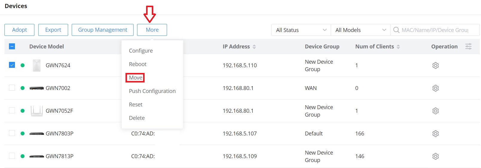
To move a GWN device to another Network, please navigate to the Devices page, select the desired devices, click on the “More” button then select “Move”, after that a pop window will appear to choose the destination network to which the selected devices will be moved.
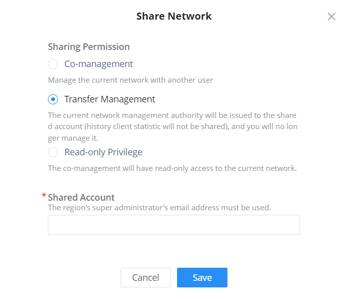
Share a Network
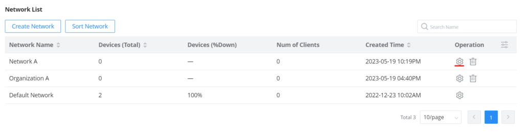
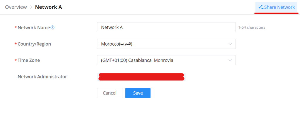
GWN Platforms allow sharing of a network among the administrators of the organization. To share a network please navigate to Organization → Overview, then click the configuration icon of the network you wish to share.
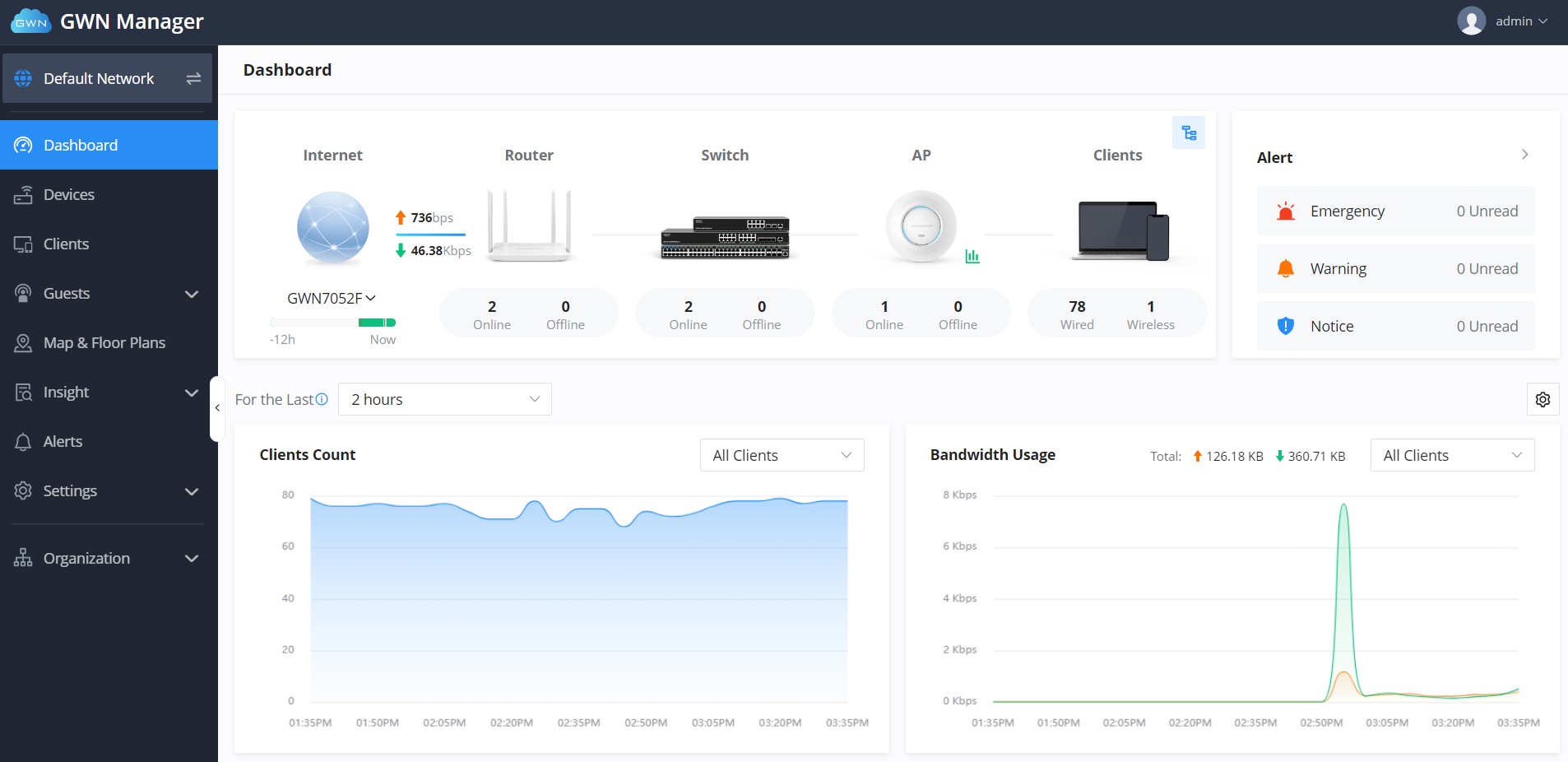
DASHBOARD
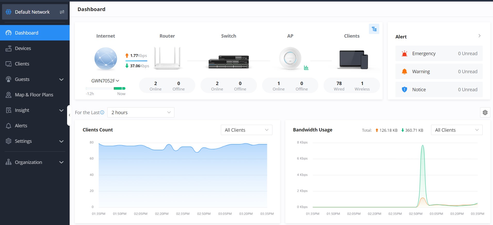
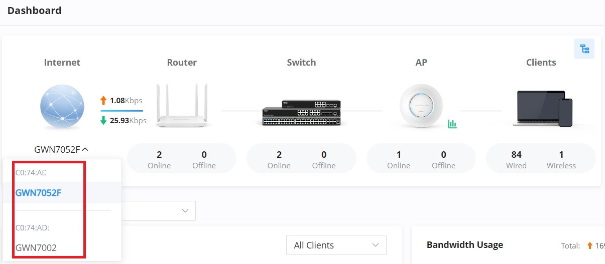
The Dashboard page provides general information that can be used to monitor GWN devices (The Router with its WAN IP, Switches, and Access Points) and Clients. It also displays the number of Devices online and offline and as for Clients it displays the number of wired and wireless clients. It also displays an Alerts preview and the user can click on ![]() icon to open the Alerts page with more details.
icon to open the Alerts page with more details.
Click on this icon  to get redirected to the Network Topology page.
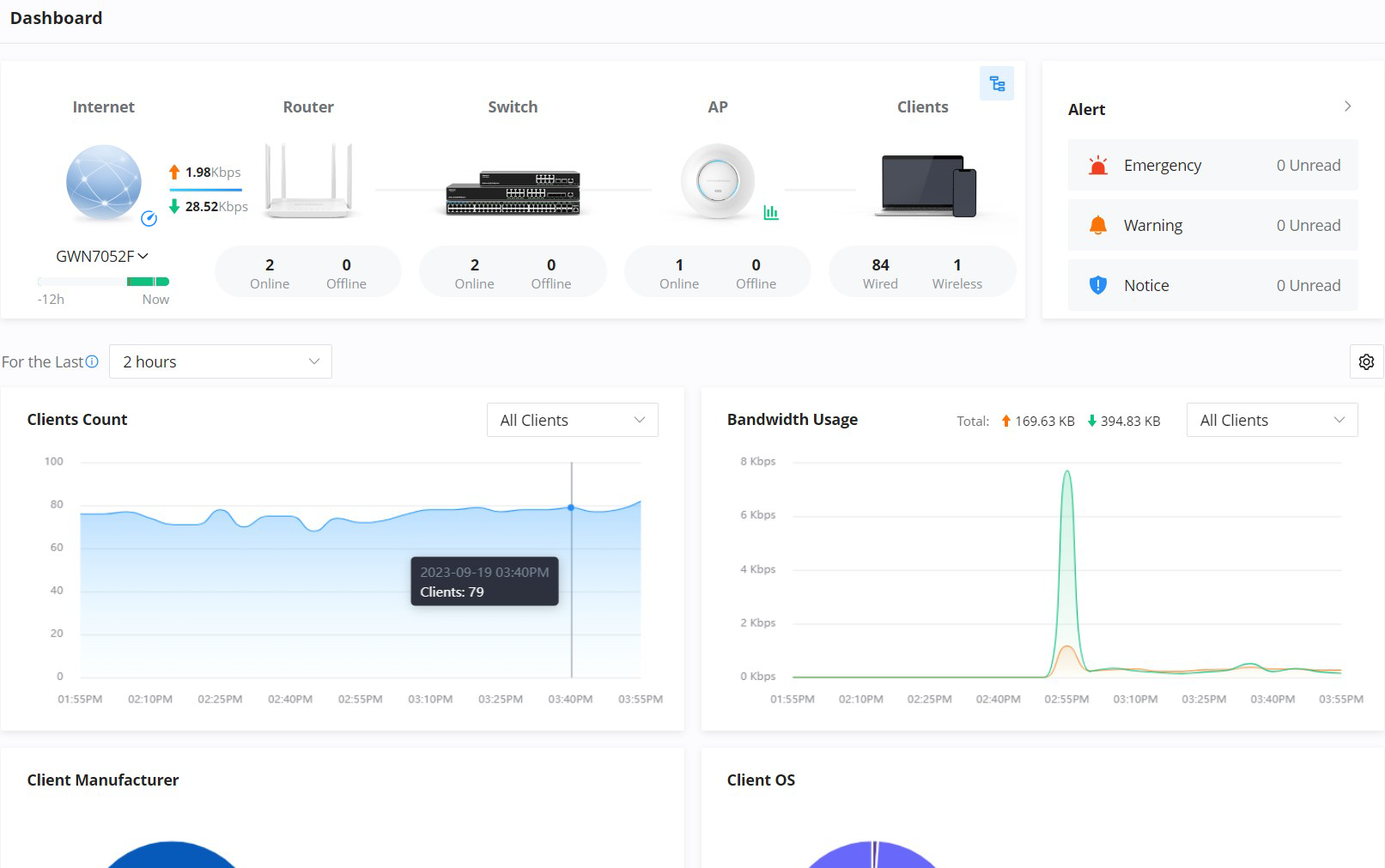
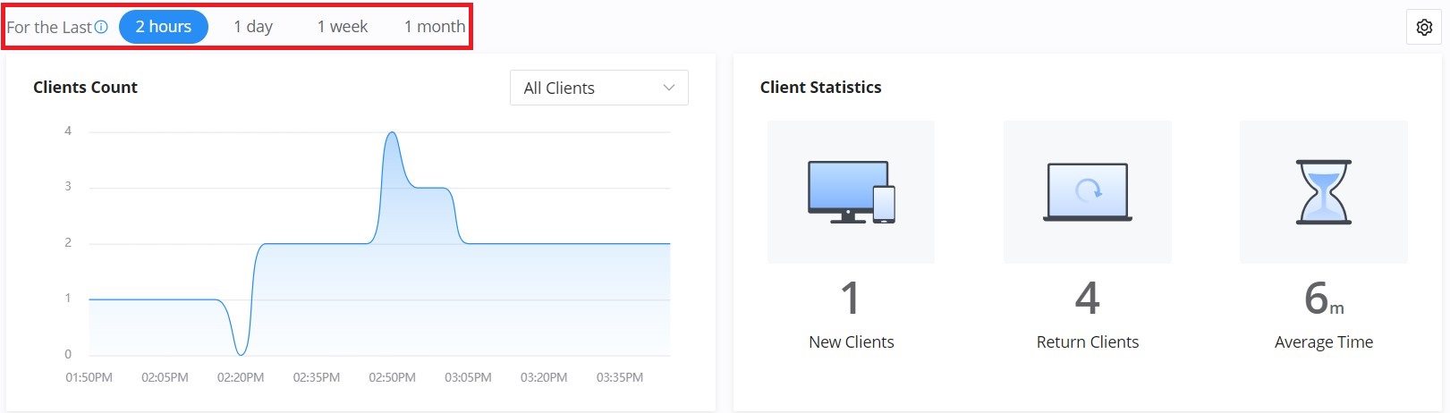
The user can choose the statistical duration of the data to review for the last 2 hours, 1 day, 1 week, 1 month, 3 months, or 6 months.
- 2 hours and one day: Refresh and record data every 5 minutes.
- 1 week: Refresh and record data every 30 minutes.
- 1, 3, and 6 months: Refresh and record data every 3 hours.
To customize the Dashboard page by adding or removing charts, please click on this ![]() icon, and refer to the figure below:
icon, and refer to the figure below:
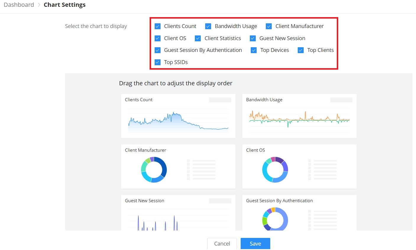
| Client Count | It shows the number of clients connected at a specific period of time. |
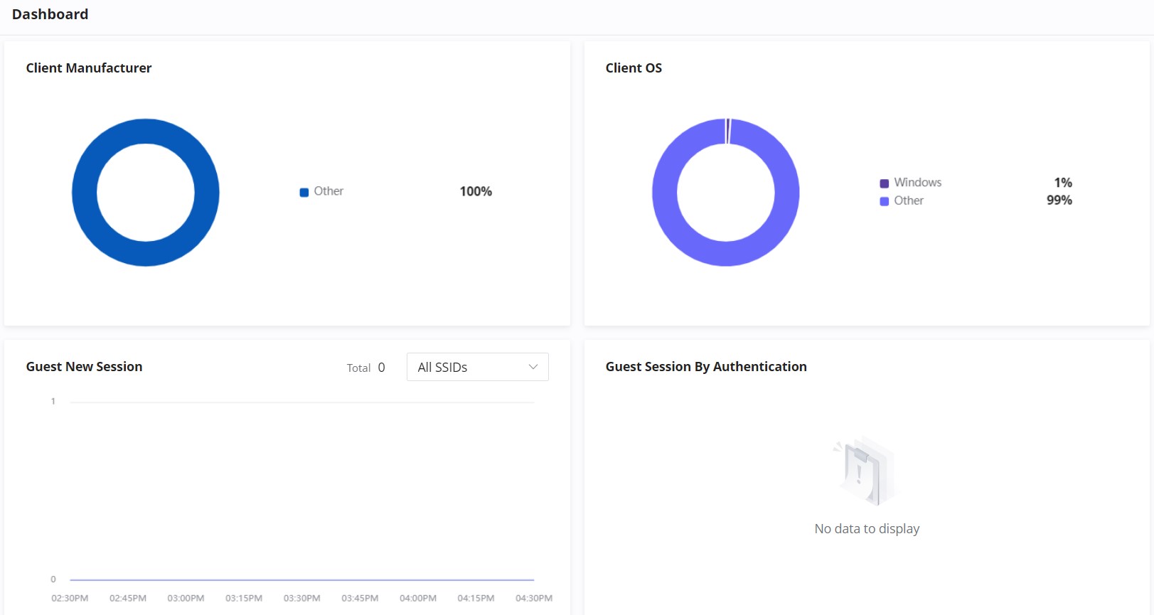
| Client OS | It shows the Operating Systems used by Clients and the percentage of each. |
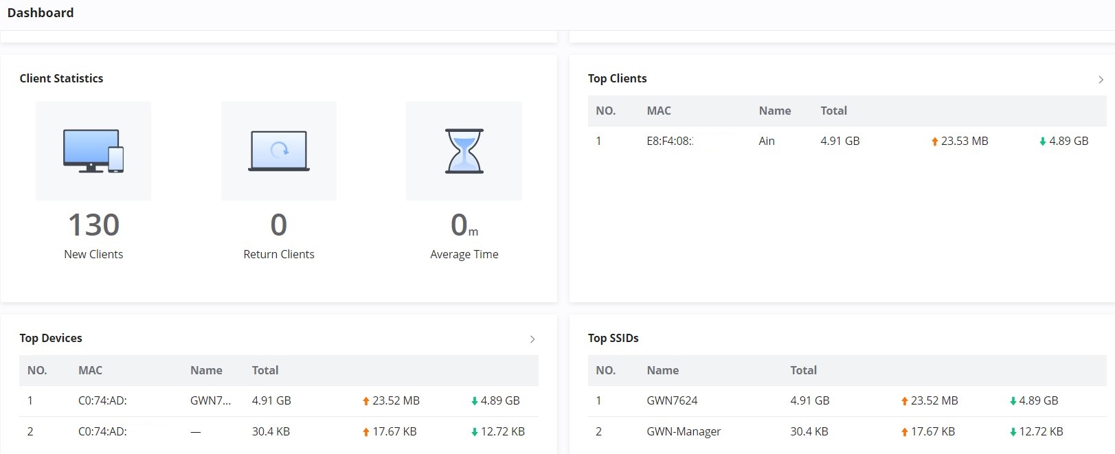
| Clients Statistics | Displays New Clients, Return Clients, and Average Time. |
| Top SSIDs | Displays the SSIDs that are mostly used by clients. |
| Bandwidth Usage | This section shows the bandwidth usage (Upload/Download) by all the clients, it provides the BW statistics for both Download and upload. |
| Guest New Session | Displays the period of time, when a new Guest session started and ended. |
| Top Clients | Lists the clients that downloaded/uploaded the max of data |
| Client Manufacturer | Displays the percentage of each Manufacturer used by Clients. |
| Guest Session by Authentication | Displays the percentage of a Guest session by Authentication |
| Top Devices | Lists the devices by the amount of the total usage. |
Example:
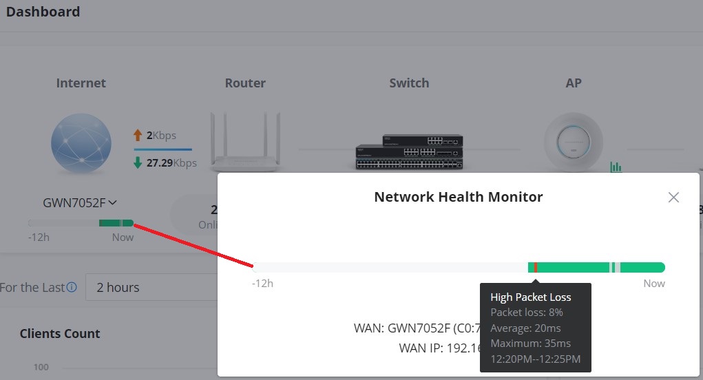
Network Health Monitor
Network Health Monitor is a feature that monitors the WAN (WAN ports or Device group) and displays the WAN status for the last 12 hours for each WAN with color code.
On the Dashboard page, under Internet section select the WAN port. Please refer to the figure below:
Then, Click on the time bar to get a full view of the last 12 hours’ status, and hover the cursor over the color to get more details and the duration. Please check the color code meaning below:
Green: Online
Grey: Offline
Red: High Packets Loss
WAN Speed Test
When a GWN router is added to the GWN Management and the WAN is added under Settings → Internet → WAN, The user can click on the speed test icon as shown below to run the speed test of the select WAN.
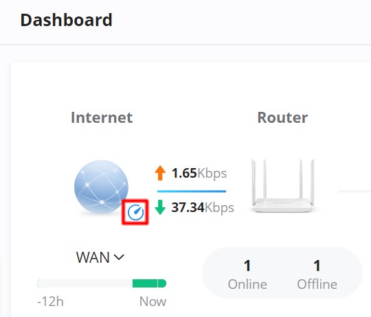
First, select the WAN under internet, then click on the speed test icon, then the download test will start.

Once the download test is over, the upload test will start next.
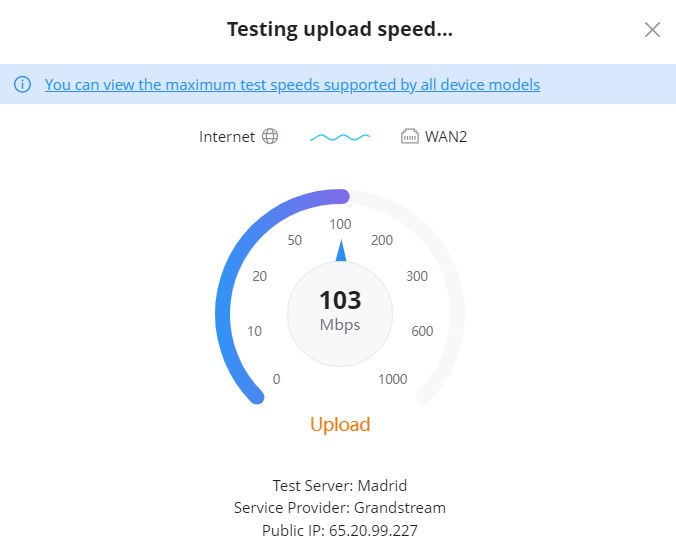
Finally, the speed test result will be shown with download, upload rates.
DEVICES
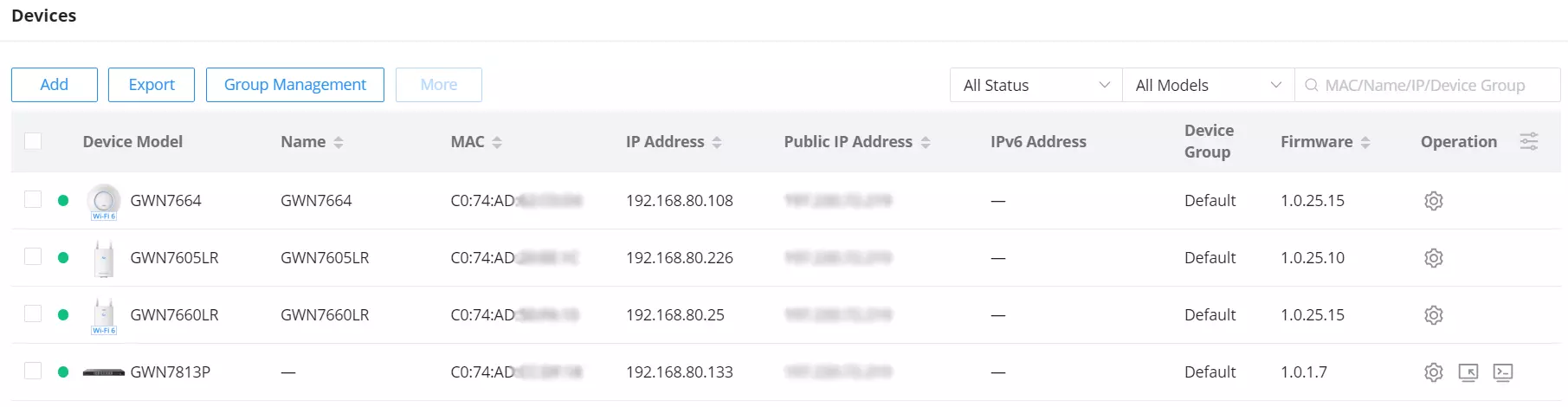
On this page, users can Add (GWN.Cloud) or Adopt (GWN manager), export a list of devices, move to a different network/Device group, reset, delete, configure, reboot, or push configuration.
Also displays all the related information for the GWN devices on the current network, to add/remove columns, click on “Parameters icon” as shown below:
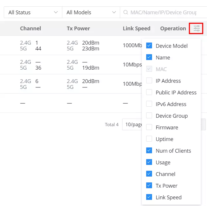
Many information can be viewed from this page:
- Device Model
- Name
- MAC address
- IP address
- Public IP address
- IPv6 address
- Device group
- Firmware
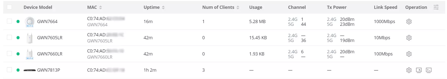
- Uptime
- Number of Clients
- Usage
- Channel: displays GWN APs used channels on all bands.
- TX Power: displays transmission power on wireless devices e.g. GWN APs in dBm.
- Link Speed: if a GWN AP is connected for example to GWN Switch on a 1Gbps port, then the link speed will be 1Gbps.
For reference, please check the examples below:
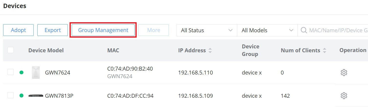
Group Management
Group management is a logical group that contains devices either for the same model or different models. This helps to make GWN devices management even easier, for example, there is a pre-set features for switches when added to a group, or when the user wants to apply certain configurations on many devices at the same time, he can apply them on the device group that contains these devices, etc.
To create or edit a Device group, please navigate to the Web UI → Devices page then click on the “Group Management” button.
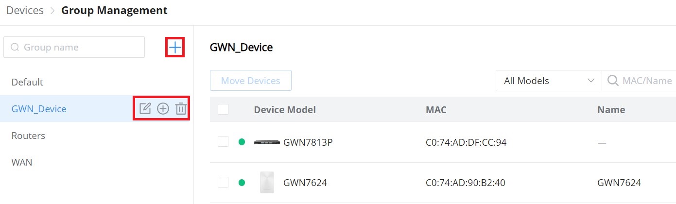
To add a new Device group or add devices to a previously created Device group click on “+” icon, to delete or modify a Device group click on the “Edit” or “Delete” icons respectively.
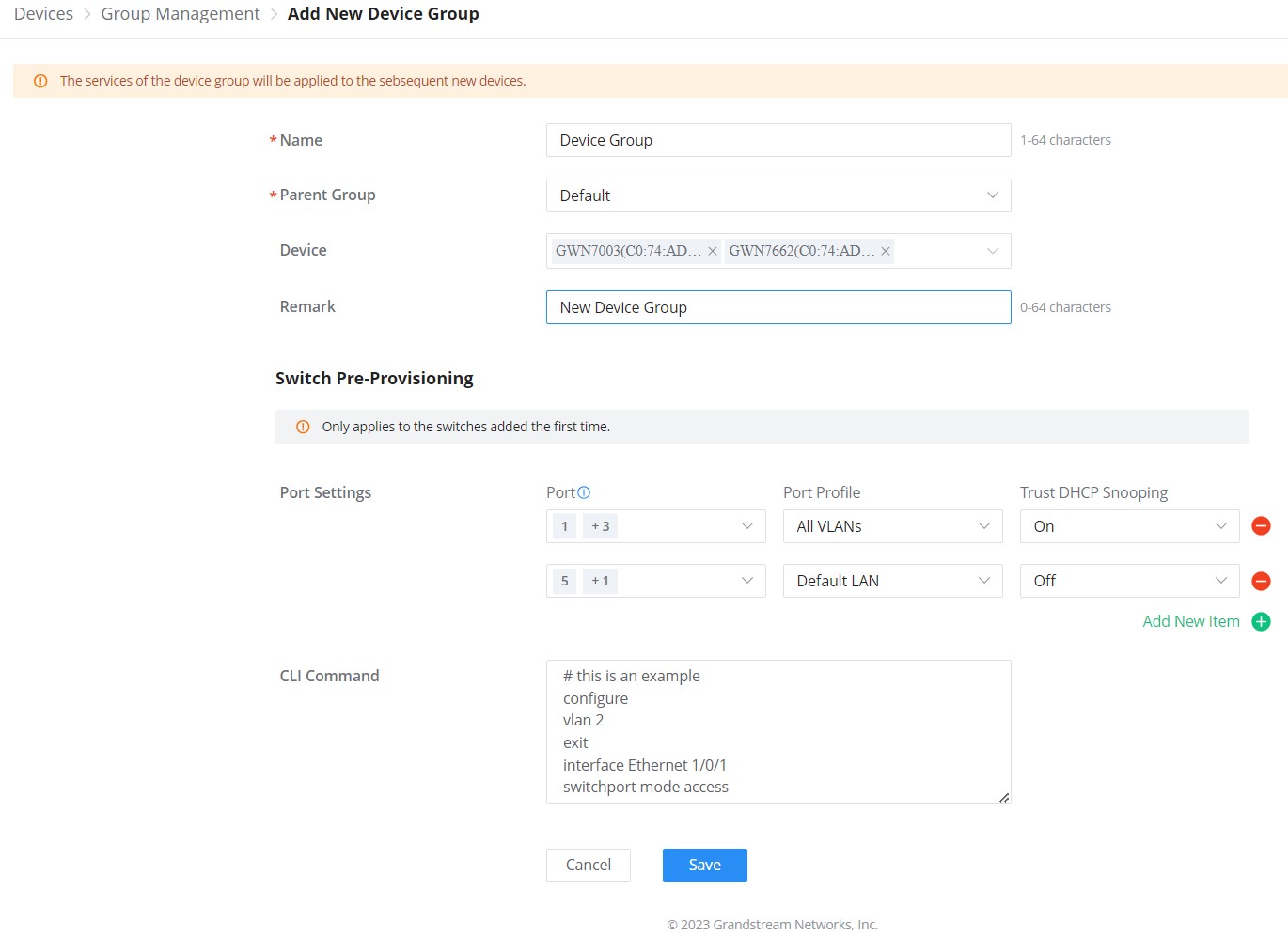
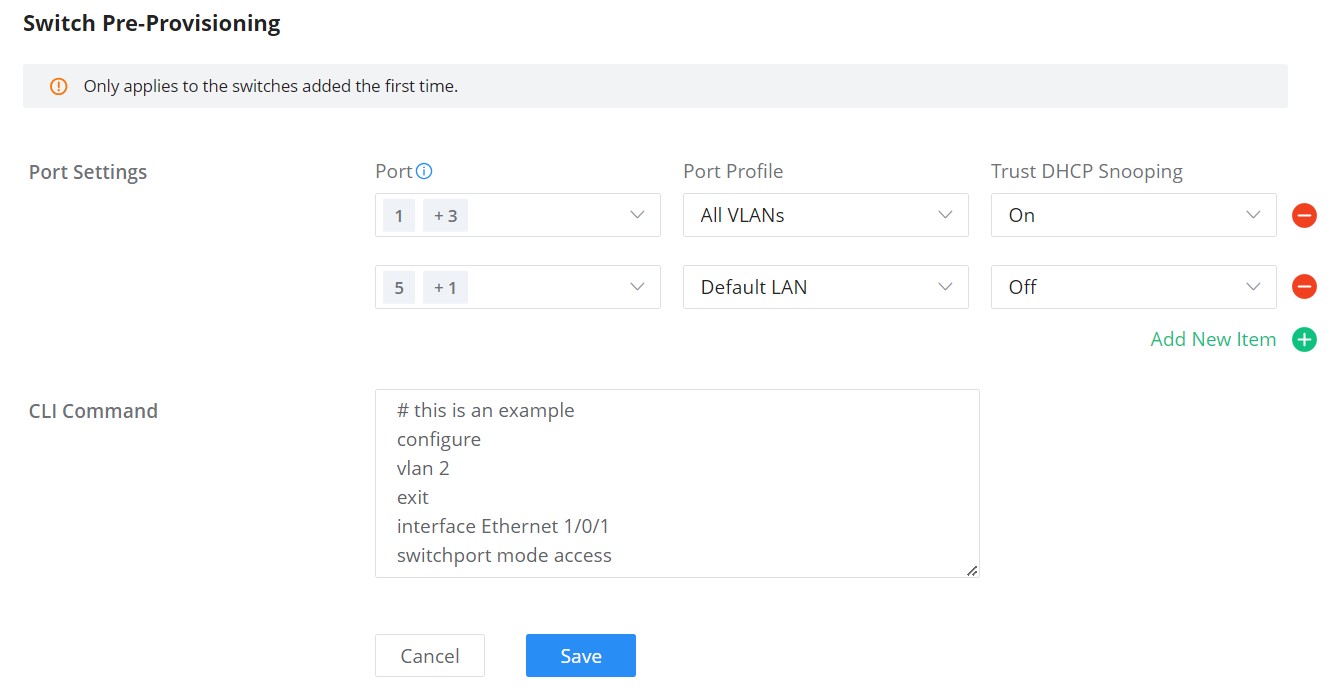
Switch Pre-Provisioning
The switch Pre-Provisioning feature allows the user to pre-configure port settings and CLI commands for the switches that belong to the same device group. Once the GWN switches are added to the device group the pre-configurations will take effect.
- Port Settings
In this section, the user can pre-configure the switch ports with a port profile and Trust DHCP Snooping (On or Off).
Click on “+” or “–” icons to add or delete port settings. Please refer to the figure below:
- CLI Command
The user can enter the CLI commands here, separated by “Enter“. Please use English and characters only, and use the “#” key for the comment line.
Push Configuration
The push configuration feature helps to push GWN.Cloud or GWN Manager configuration to the local side of added GWN devices either manually or automatically.
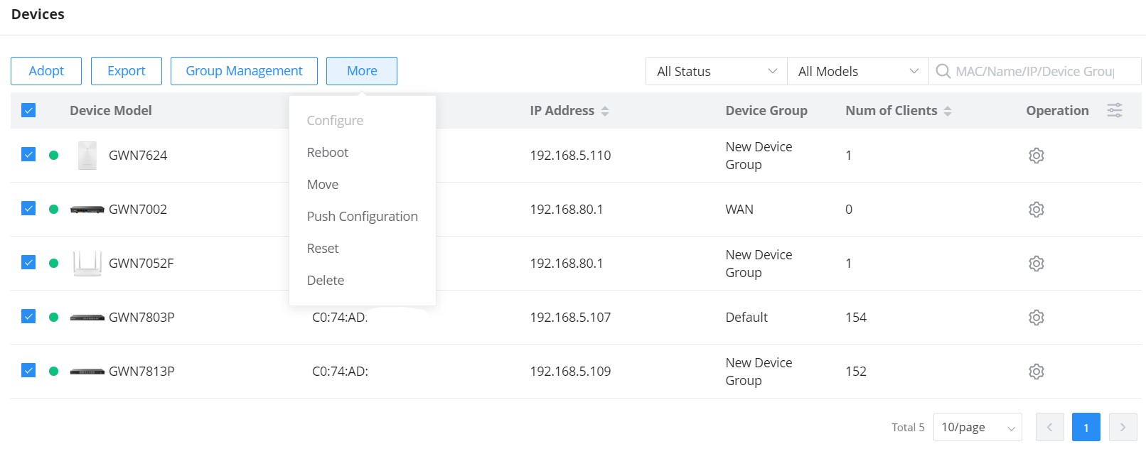
Manual Method
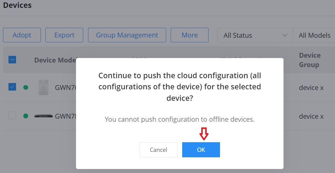
To manually push the GWN.Cloud/GWN Manager configuration to the local side of a GWN device, please navigate to Web UI → Devices page, then select a device and click on the “More” button, next click on “Push Configuration“.
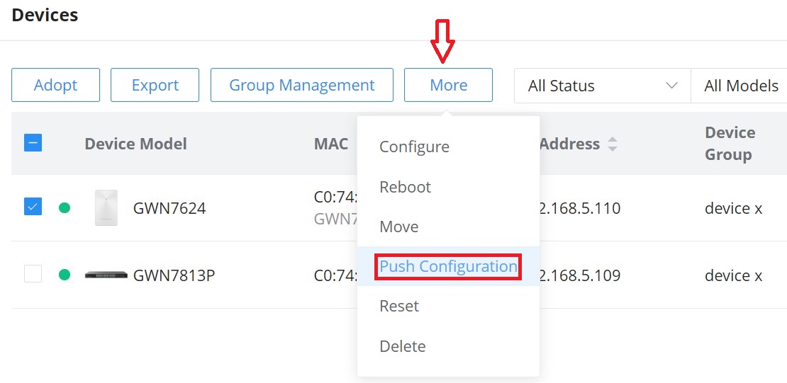
A confirmation dialog will pop up to confirm the push configuration, to proceed click on the “OK” button.
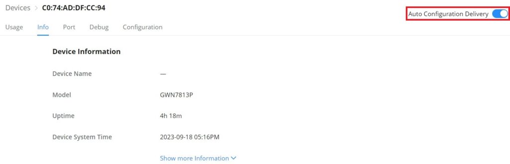
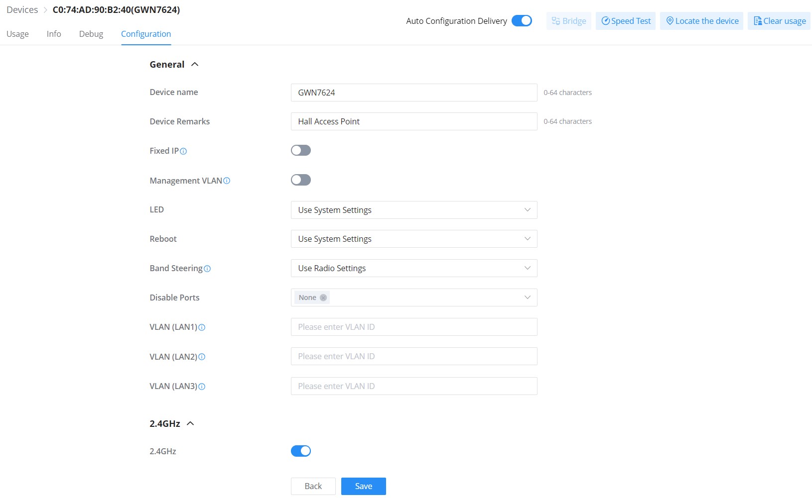
Automatic Method
If the user wants to push the GWN.Cloud/GWN Manager configuration automatically for the selected GWN device, navigate to Web UI → Devices page, then click on a GWN device or configuration icon, on the top of the page toggle ON “Auto Configuration Delivery“, please refer to the figure below:
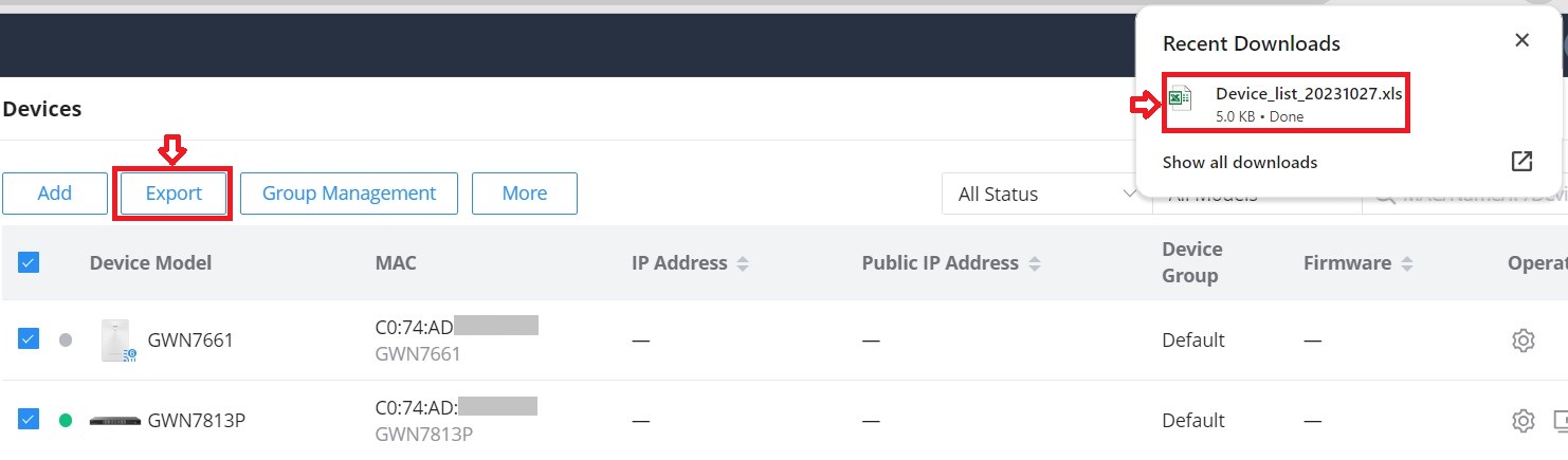
Export
The user can click on the “Export” button to download a file (Excel file) that contains all the devices on this network with details. Please refer to the figures below:
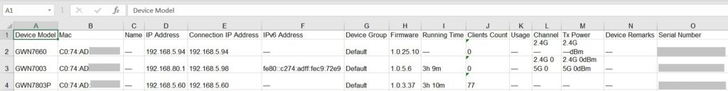
The exported file contains the following information about all the devices:
- Device Model
- MAC Address
- Name
- IP Address
- Connection IP Address
- IPv6 Address
- Device Group
- Firmware Version
- Running Time
- Clients Count
- Usage
- Channel (For GWN APs & GWN Wireless Routers)
- Tx Power
- Device Remarks
- Serial Number
More
To view more options, please click on the “More” button as shown below:
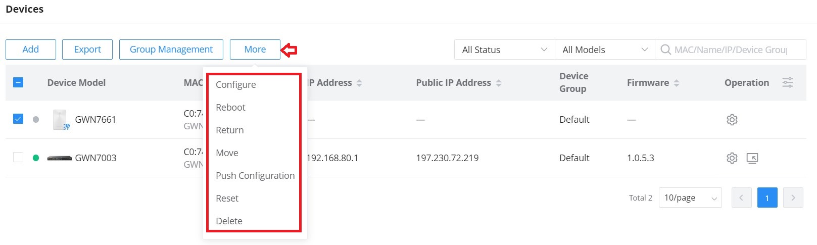
Reboot: to reboot the GWN device.
Return: Returning a device will transfer it from its current network to the inventory, where it can be reassigned.
Move: to move a device from the current network to another network.
Reset: to reset a device.
Delete: to delete a device.
Operation
Under Operation, the user can find more tools that can help with managing GWN devices.
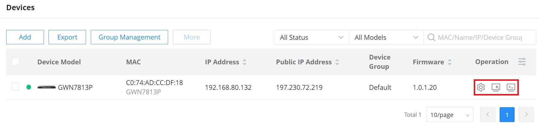
![]() : Click to configure the GWN device.
: Click to configure the GWN device.
![]() : Remove access to the GWN device Web UI.
: Remove access to the GWN device Web UI.
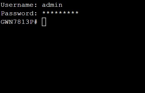
![]() : Web CLI.
: Web CLI.
Configure a device
The configuration page allows the administrator to name, reboot, configure, etc. GWN devices.
Navigate to the Web UI → Devices page, then click on a GWN device entry or click on the configuration icon.
Configure a GWN Access Point
On the Devices page, when the user clicks on a GWN Access point, there are many options on the top of the page dedicated only to GWN Access points:
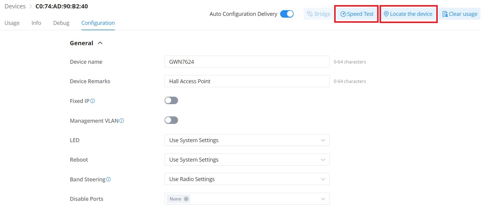
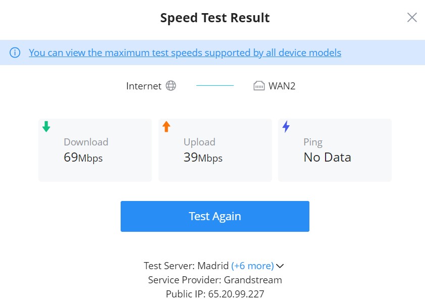
- Speed Test: is a feature on GWN APs to run a speed test directly from GWN.Cloud or GWN manager, making it easier for the administrators to check many GWN APs’ performance from one single interface. For more details, please refer to the figures below:
To start running the speed test, click on the “Speed Test” button, refer to the figure above.
The first speed test is testing download speed.
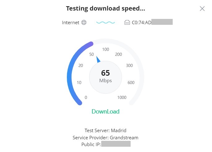
Once, the download speed test is over, the second test is testing upload speed.
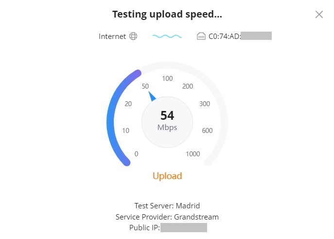
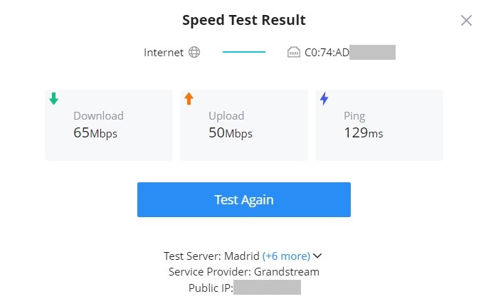
Finally, the user will be able the see the final result, including Download/Upload speed and also the Ping response time in ms (Millisecond). To run the speed test again, click on the “Test Again” button.
- Locate the device: easily locate the device by clicking on the “Locate the device” button, a white light will flash for 2 minutes, or click on the “Close” button.
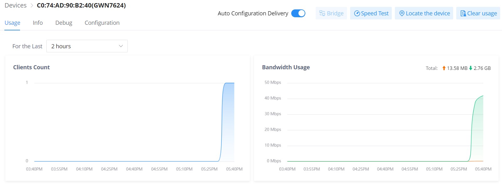
- GWN Access Point – Usage
This page shows the usage of the GWN AP (Bandwidth usage and Client Count) the data shown can be filtered from 2 hours up to 1 month.
Clear usage: to clear collected data from the AP (Bandwidth usage and Client Count).
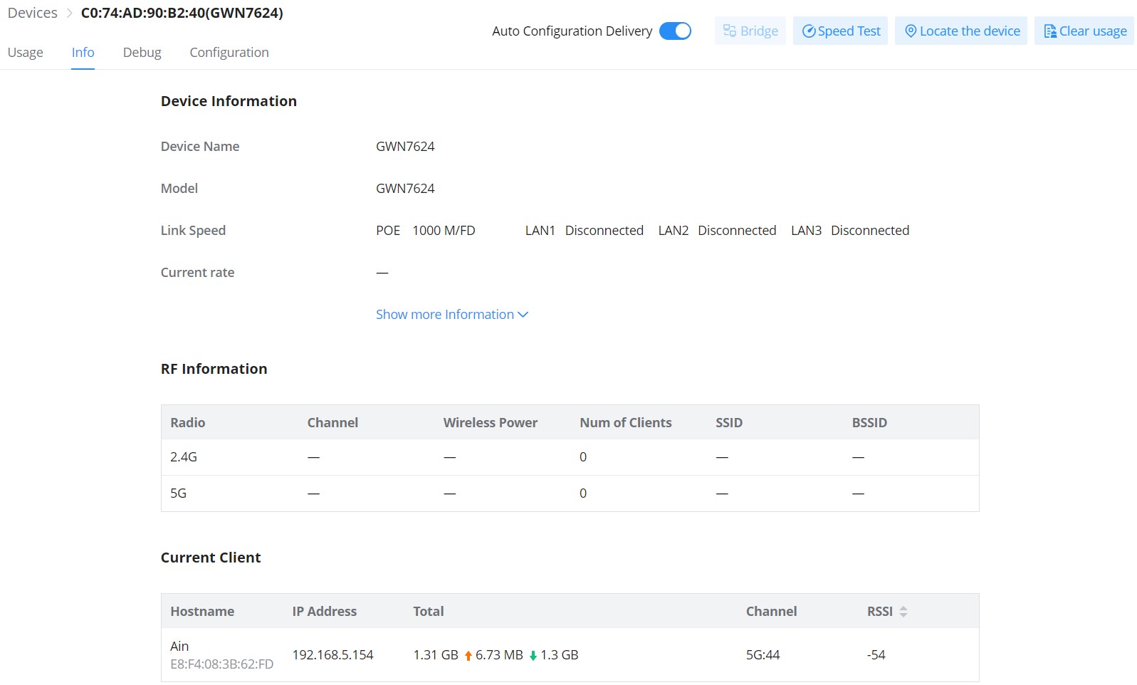
- GWN Access point – Info
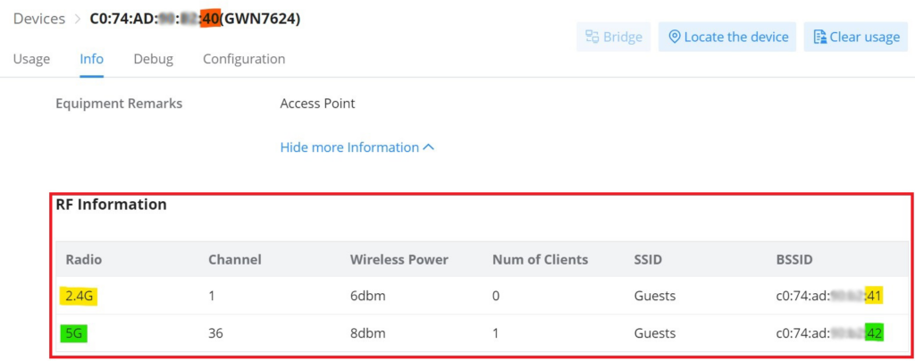
On this page, info related to the GWN AP information (firmware, UPtime, etc), RF (Radio Frequency), and Current Client can be found here.
RF Information (BSSID)
The Basic Service Set Identifier (BSSID) is the MAC address of the wireless interface or precisely the radio antenna (2.4GHz or 5GHz). For example, on the GWN7624 access point, we will have two BSSIDs, one for the 2.4GHz antenna and another BSSID for the 5GHz antenna. The two MAC addresses for both antennas will be based on the original device MAC address. In our example, GWN7624 MAC address is C0:74:AD:XX:XX:40 then the 2.4GHz antenna BSSID is C0:74:AD:XX:XX:41, and for the 5GHz antenna is C0:74:AD:XX:XX:42. Access points include the BSSID in their beacons and probes responses.
Navigate to web UI → Devices → Info then scroll down to RF Information (BSSID). Refer to the image below.
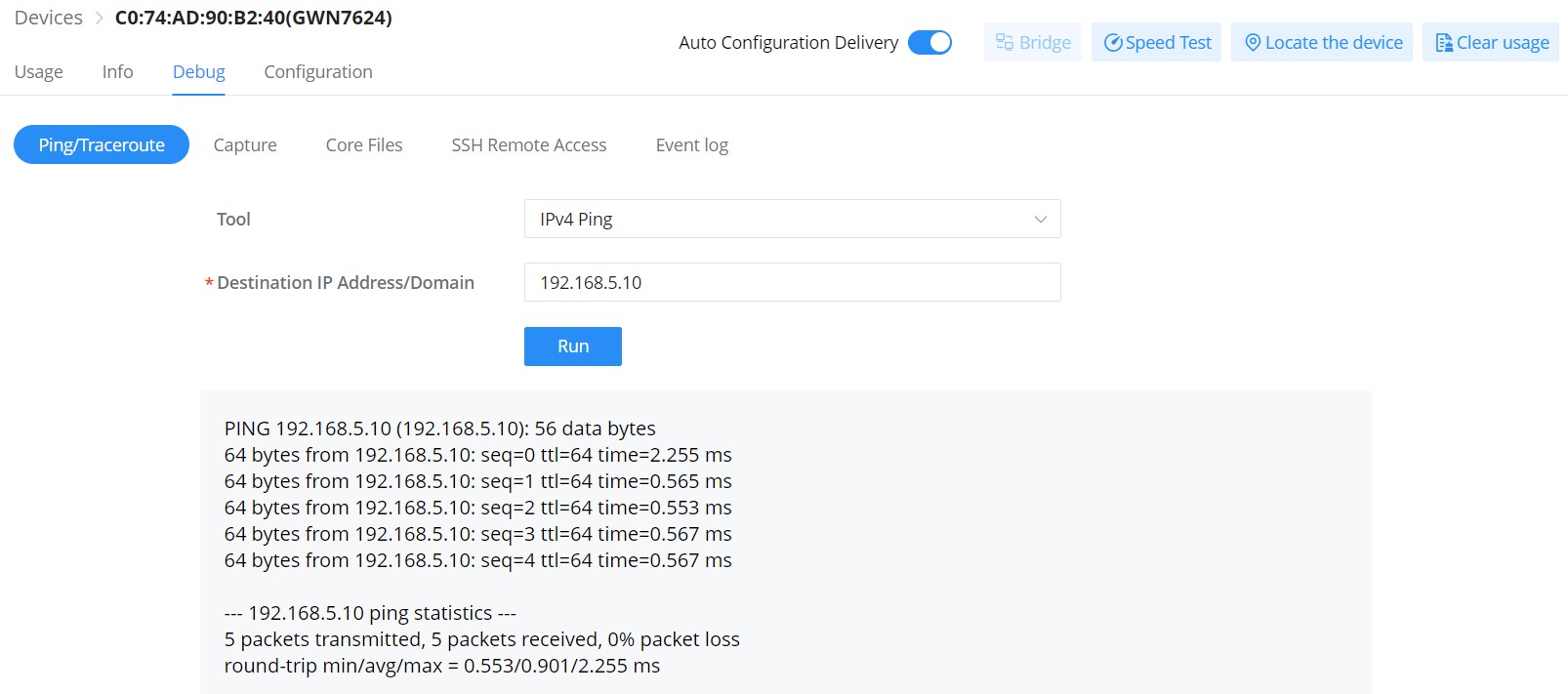
- GWN Access point – Debug
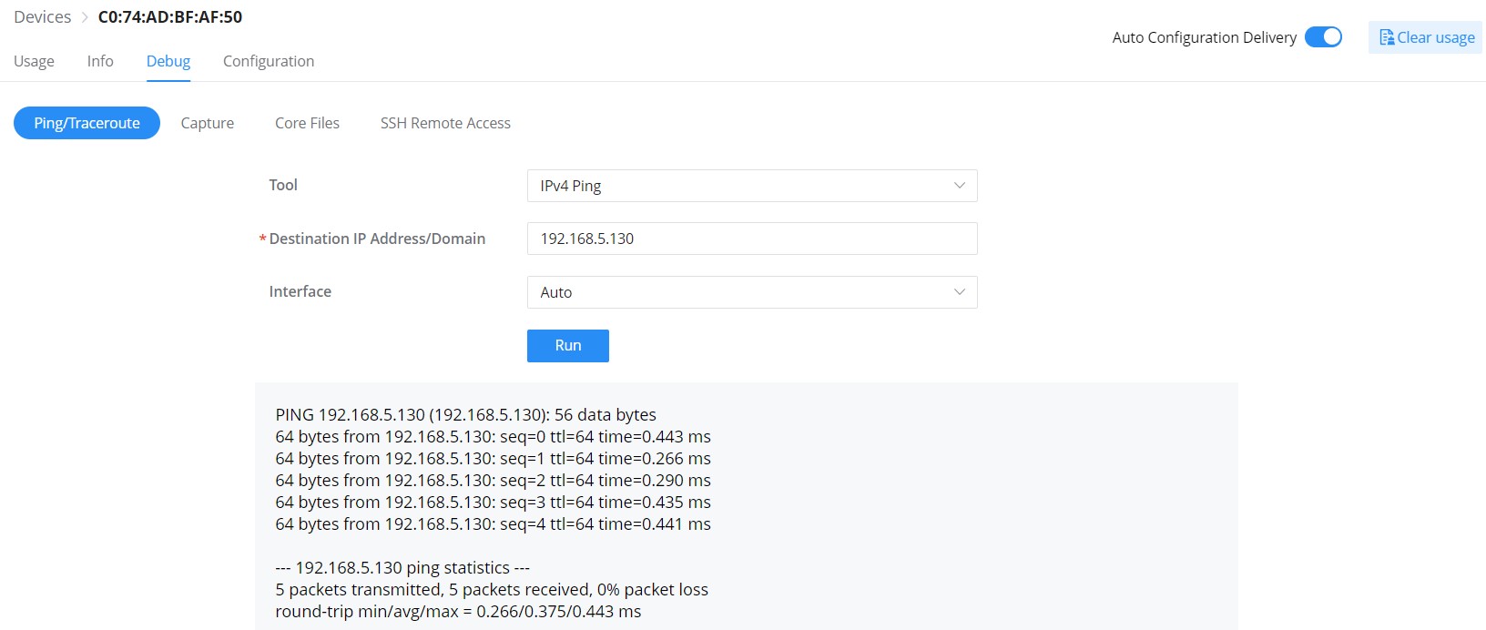
GWN APs have many debug tools to help diagnose the issues:
- Ping/Traceroute: Ping and traceroute to check the reachability or the trace of an IP/Domain.
- Capture: to capture the traffic of GWN AP or GWN.Cloud/Manager (a file will be downloaded to your local machine).
- Core Files: Core Files will be listed here when generated.
- SSH Remote Access: to allow SSH remote access
- Event log: a list of events related to the GWN AP.
- GWN Access point – Configuration
On this page, the administrator can configure GWN AP-related settings like (name, band steering, VLAN, RF, etc). This configuration is only limited to this GWN AP.
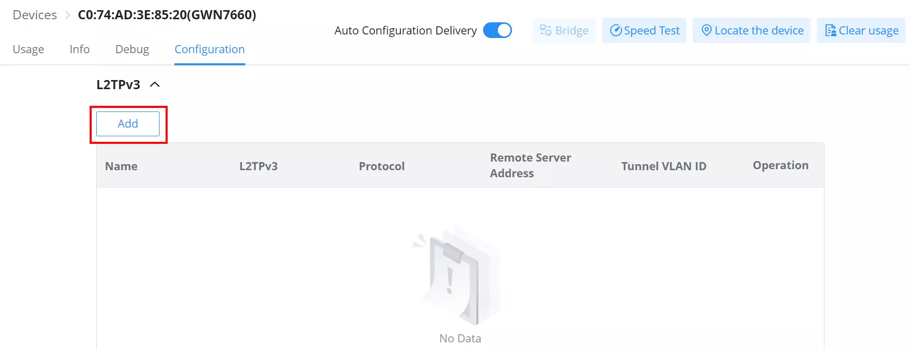
- GWN AP L2TPv3
L2TPv3 (Layer 2 Tunneling Protocol version 3) is a versatile protocol widely utilized for tunneling Layer 2 traffic over IP networks. When implemented on GWN Access Points acting as L2TP Access Concentrators (LACs) connecting to a central L2TP Network Server (LNS), it enables seamless and secure communication for wireless clients.
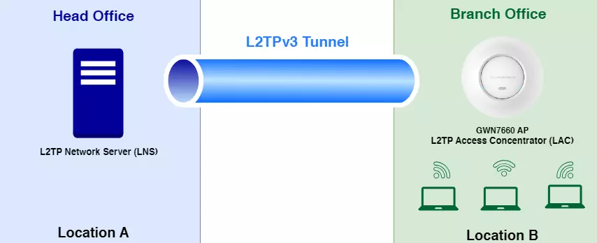
GWN Access Points, known for their reliability and performance, acting as LACs establish tunnels to the LNS, facilitating the encapsulation and transmission of all wireless clients’ Layer 2 traffic. This architecture proves particularly beneficial in centralized network models where VLANs extend from corporate environments to remote branch sites.
By leveraging L2TPv3, wireless clients associated with GWN Access Points are seamlessly integrated into the corporate network infrastructure. They receive IP addresses dynamically from the DHCP server hosted on the LNS, ensuring efficient network resource allocation and management.
This integration empowers organizations with scalable and secure wireless connectivity solutions, optimized for various deployment scenarios. Whether for small businesses or enterprise environments, the utilization of L2TPv3 on GWN Access Points offers a robust framework for extending network capabilities while maintaining high levels of performance and security.
To add a L2TPv3 tunnel, click on “Add” button as shown below:
Please refer to the figure and table below:
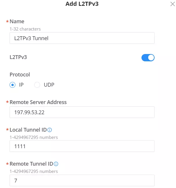
Name | Set the name of the tunnel. |
L2TPv3 | Enable/Disable the tunnel. |
Protocol | Set the encapsulation type of the tunnel. Valid values for encapsulation are: UDP, IP. |
Remote Server Address | Set the IP address of the remote peer. |
Local Tunnel ID | Set the tunnel id, which is a 32-bit integer value. This uniquely identifies the tunnel. |
Remote Tunnel ID | Set the peer tunnel id, which is a 32-bit integer value assigned to the tunnel by the peer. |
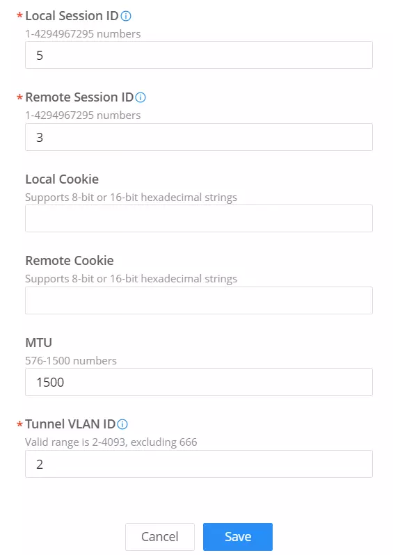
Local Session ID | Set the session id, which is a 32-bit integer value. This uniquely identifies the session being created. The value used must match the peer_session_id value being used at the peer. |
Remote Session ID | Set the peer session id, which is a 32-bit integer value assigned to the session by the peer. The value used must match the session_id value being used at the peer. |
Local Cookie | Set an optional cookie value to be assigned to the session. This is a 4 or 8 byte value, specified as 8 or 16 hex digits, e.g. 014d3636deadbeef. The value must match the peer_cookie value set at the peer. The cookie value is carried in L2TP data packets and is checked for expected value at the peer. Default setting is no cookie used. |
Remote Cookie | Set an optional peer cookie value to be assigned to the session. This is a 4 or 8 byte value, specified as 8 or 16 hex digits, e.g. 014d3636deadbeef. The value must match the cookie value set at the peer. It tells the local system what cookie value to expect to find in received L2TP packets. Default is no cookie used. |
MTU | Set the MTU. Note: Please make sure the MTU values are consistent with the INS values. |
Tunnel VLAN ID | Specify the VLAN ID Note: The tunnel ID must be set in SSID, and make sure that SSID only has the AP(s) who enabled L2TPv3. |
Add L2TPv3
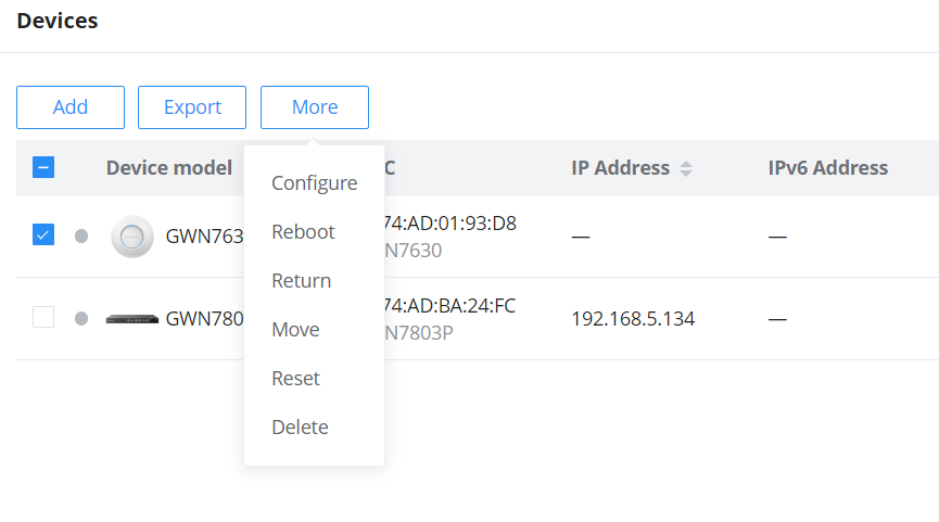
Configure GWN Access Points in Batches
GWN Management platforms allow configuring GWN access points in batches, to do that please select the access points, click on “More”, then click “Configure” as shown in the figure below.
Configure a GWN Router/GCC device
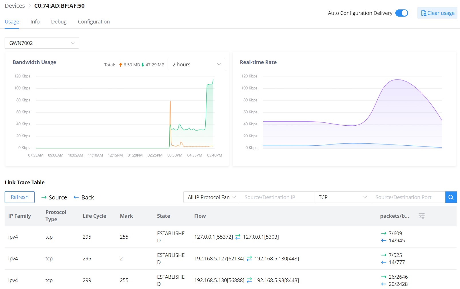
- GWN Router/GCC device – Usage
Same as the GWN AP usage tab, on this page, the user can find usage related to the GWN Router and G CC device, like bandwidth usage, Real-time Rate, and even a Link Trace Table for detailed traffic data. Please refer to the figure below:
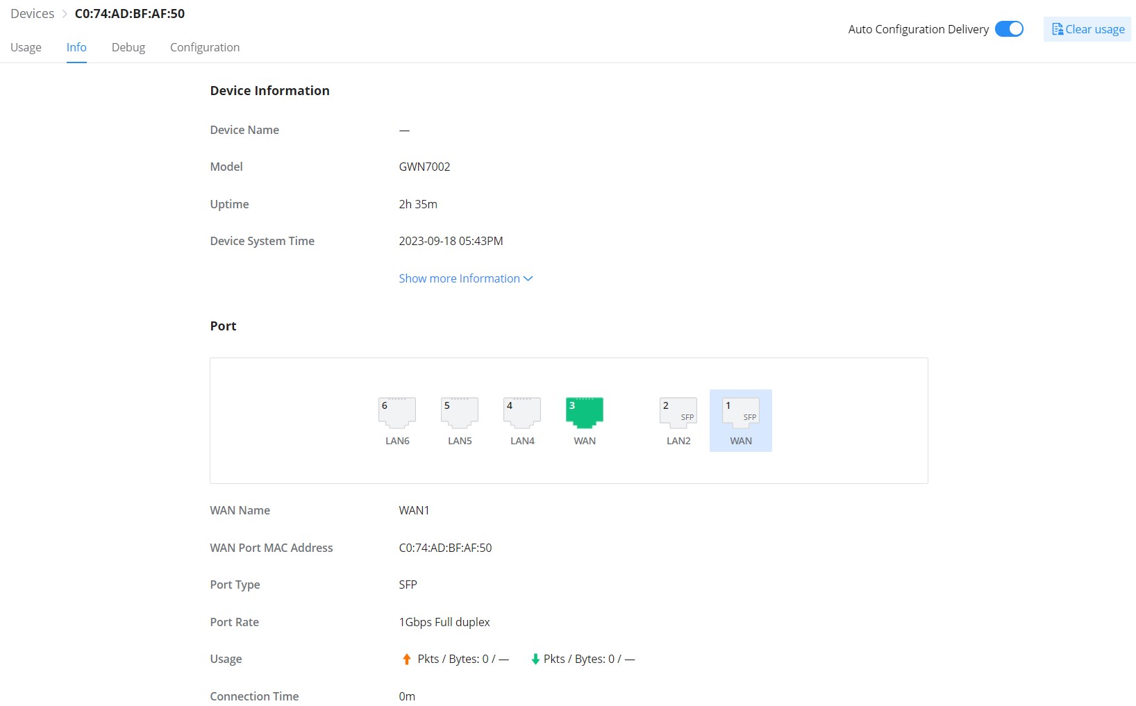
- GWN Router/GCC Device – Info
All the information related to the GWN router can be found here, including Device information (name, firmware, etc), GWN router ports’ status (active ports), and information about IPv4 and IPv6 (IP address, DNS, etc).
- GWN Router/GCC Device – Debug
The same debug tools found on GWN APs can be found here, please check GWN Access Points.
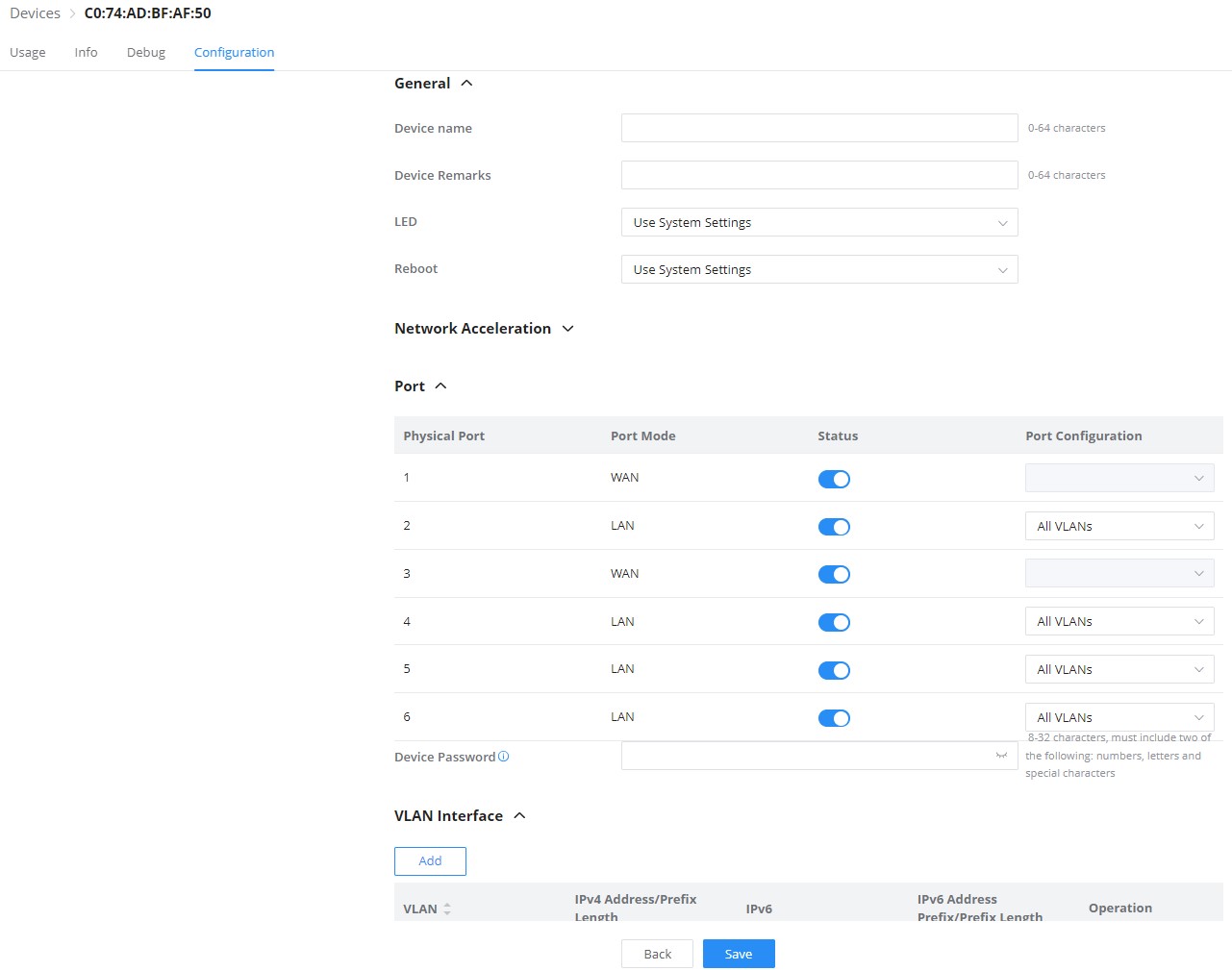
- GWN Router/GCC Device – Configuration
On the GWN router/GCC device configuration tab, the user can configure device name, and Network Acceleration, enable disable physical ports (WAN/LAN), and add/edit VLAN interfaces. Please refer to the figure below:
VLAN Interface (interface for GWN routers/GCC device)
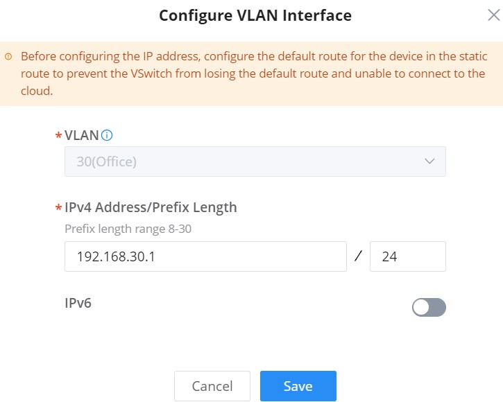
VLAN Interface as the name suggests turns a VLAN into a virtual interface that can be routed using layer 3 routing by giving this interface an IP address. To add a VLAN interface for GWN routers/GCC device, please click on the “Add” button or configure a previously created one by clicking on the “Configure icon” under operation, refer to the figure below:
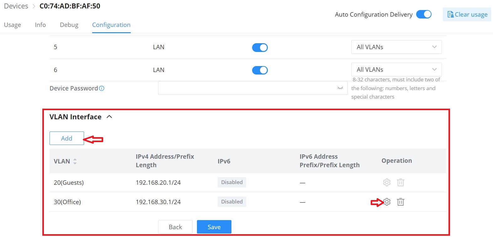
Then, select the VLAN from the list or visit the LAN page to create a VLAN (with or without DHCP Server) first in case there are no VLANs listed, then specify an IPv4 or IPv6 Address/Prefix for this VLAN interface.
Configure a GWN Switch
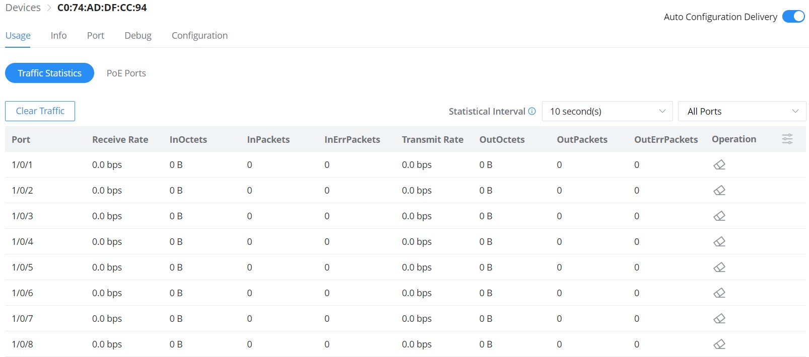
- GWN Switch – Usage
As for the GWN Switches usage tab, traffic statistics or PoE Ports power usage can be found here. The user can click on the “Clear Traffic” button to clear all the traffic or click on the “clear” icon under operation to clear traffic only for a specific port.
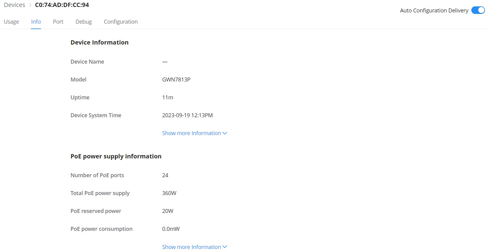
- GWN Switch – Info
Relevant GWN switch information or PoE power supply information can be found here.
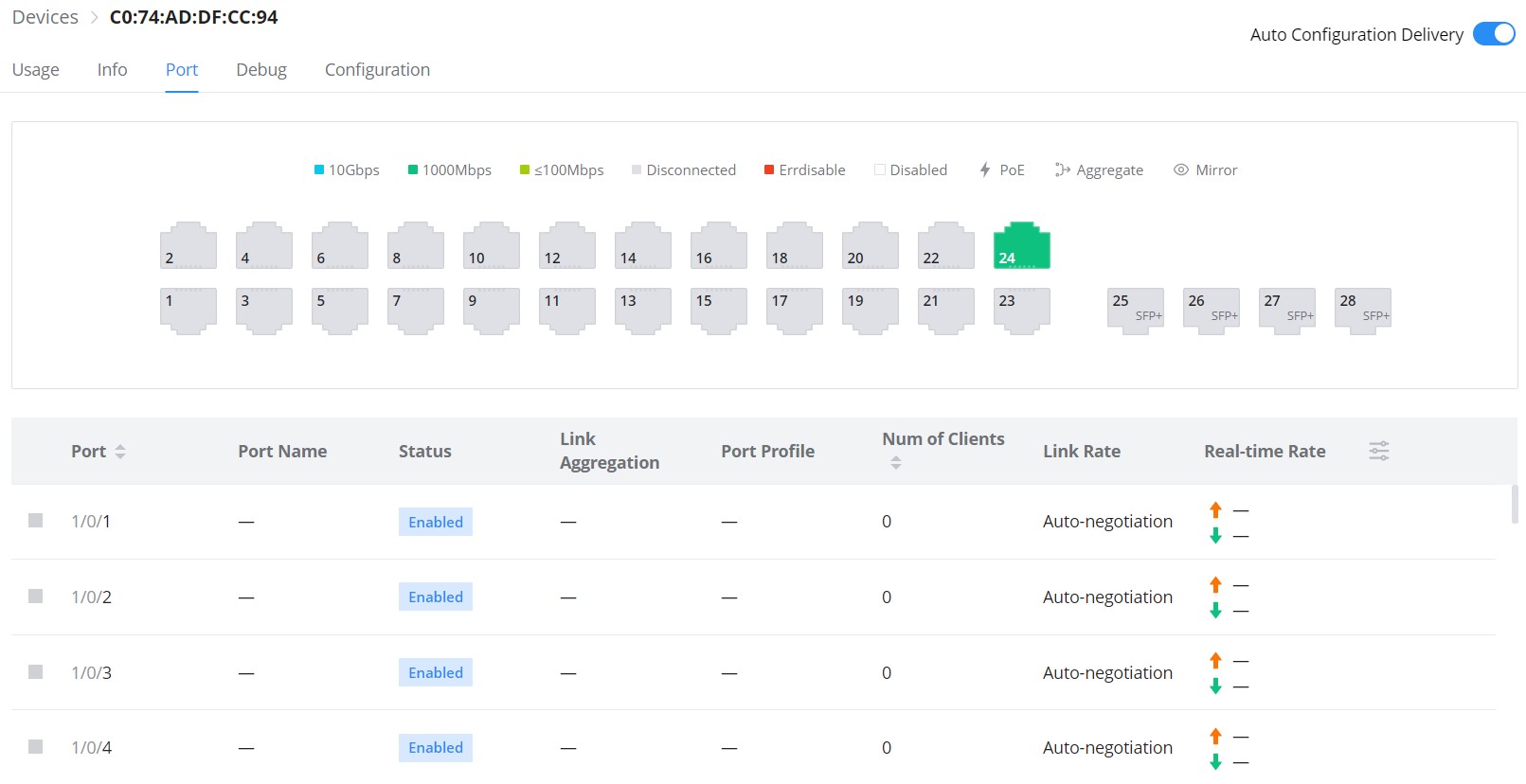
- GWN Switch – Port
On the Port tab, under devices configuration only for GWN switches, the user can view GWN switch ports status and also configure them (enable/disable a port, Link Aggregation, Port Mirroring, etc). Please refer to the figure below:
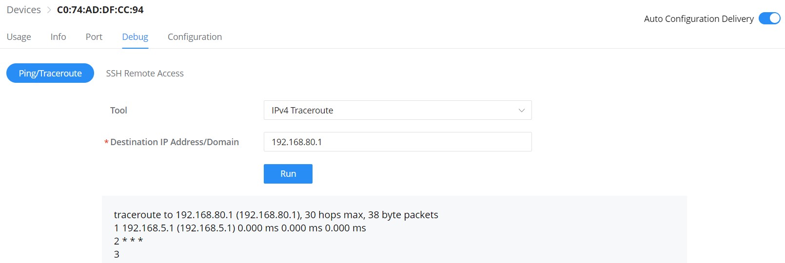
- GWN Switch – Debug
Debugging tools like ping/traceroute are also available for GWN switches, as well as SSH Remote Access.
- GWN Switch – Configuration
On this tab, under devices (only for GWN switches), the user can configure GWN switch-related configurations like switch name, RADIUS Authentication, and VLAN interfaces.
Device Password: Set the device’s SSH remote login password other than APs, which is also the device’s web login password.
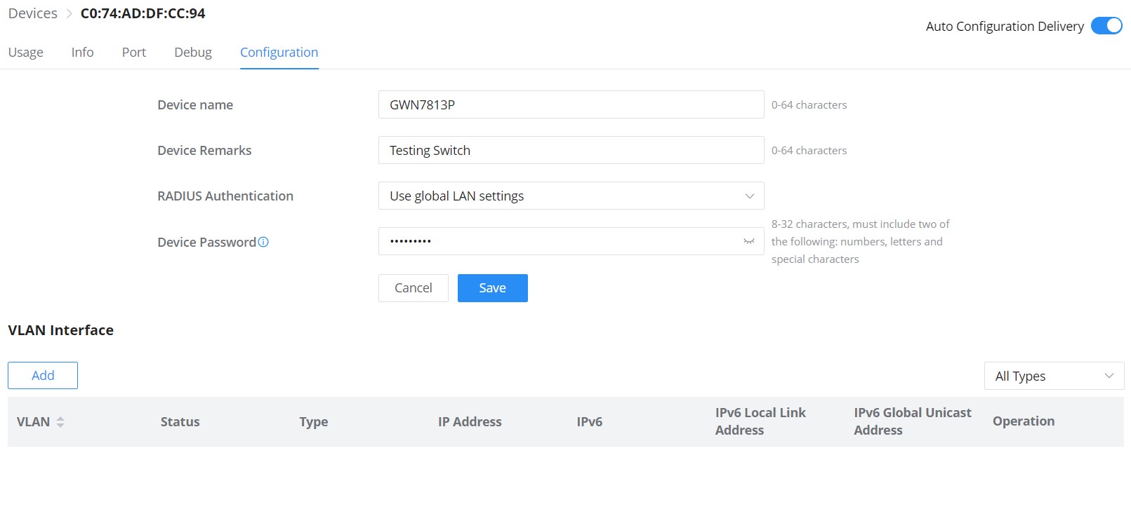
VLAN Interface (interface for GWN switches)
Hosts in different VLANs cannot communicate directly and need to be forwarded through routers or layer 3 switching protocols.
A VLAN interface is a virtual interface in Layer 3 mode and is mainly used to implement Layer 3 communication between VLANs, it does not exist on the device as a physical entity. Each VLAN corresponds to an interface by configuring an IP address for it, it can be used as the gateway address of each port in the VLAN so that packets between different VLANs can be forwarded to each other on Layer 3 routing through the VLAN interfaces. GWN switches support IPv4 interfaces as well as IPv6.
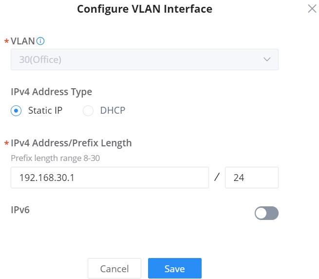
To add a VLAN Interface for GWN switches, click on the “Add” button or click on the “Configure icon” to edit a previously added one. Refer to the figure below:
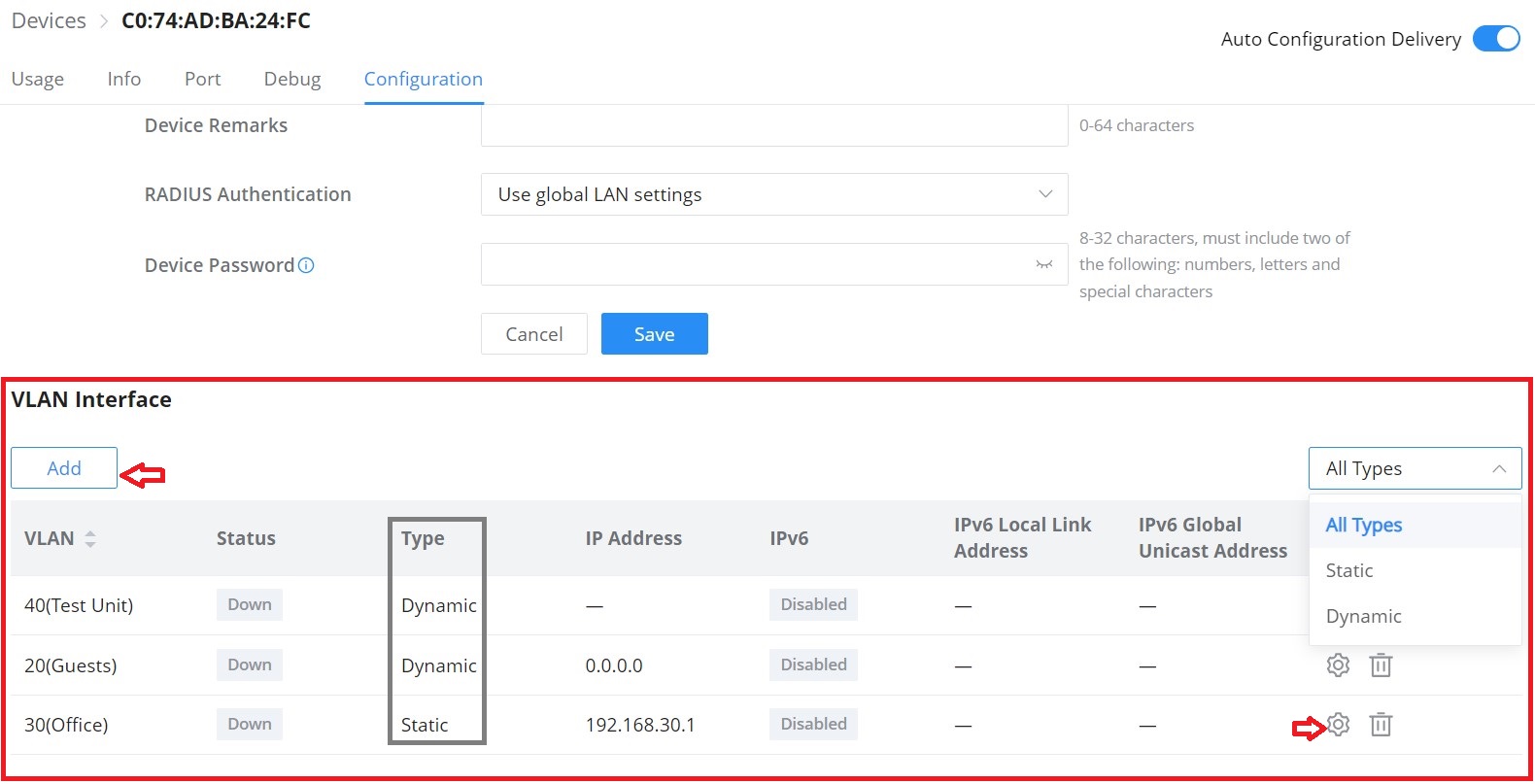
- If DHCP is selected: hosts will obtain IP addresses automatically from whatever DHCP pool is configured for example a router.
- If Static IP is selected: for hosts to obtain IP addresses, the user must configure a VLAN with DHCP Server, and create or edit VLAN first LAN.
CLIENTS
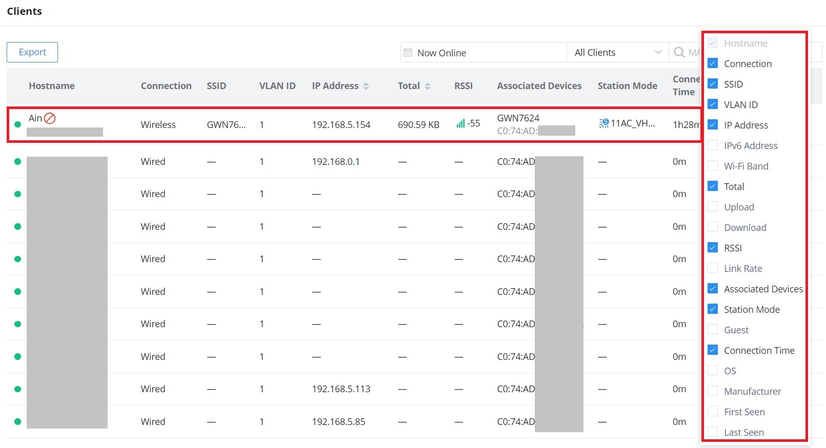
From The client’s page, the administrator can monitor and manage all the clients connected to the network/GWN devices. A list of all connected clients with their related info like connection type, IP Address, Total bandwidth, Associated Devices (GWN AP, Router or switch), etc. will be also displayed, for more info about the client or related configuration please click on the client or click on the configuration icon. Please refer to the figure below:
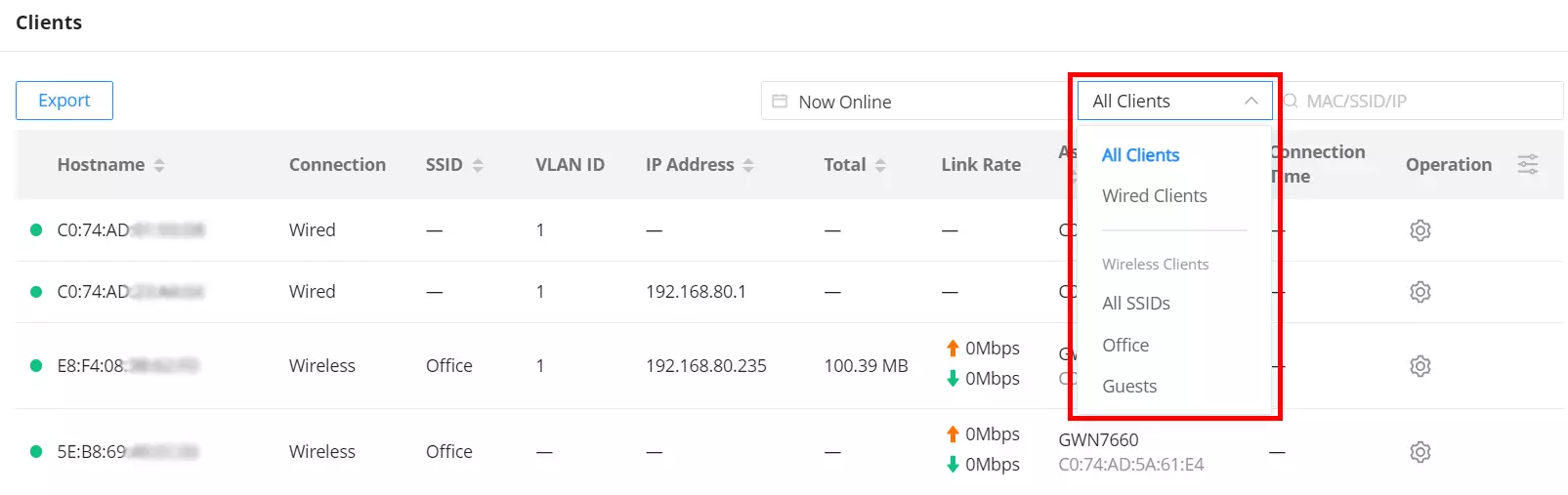
To make it easier for the users to find the connected clients, it’s possible to filter by wired clients or wireless clients and even by SSID e.g. (Office, Guests …), please refer to the figure below:
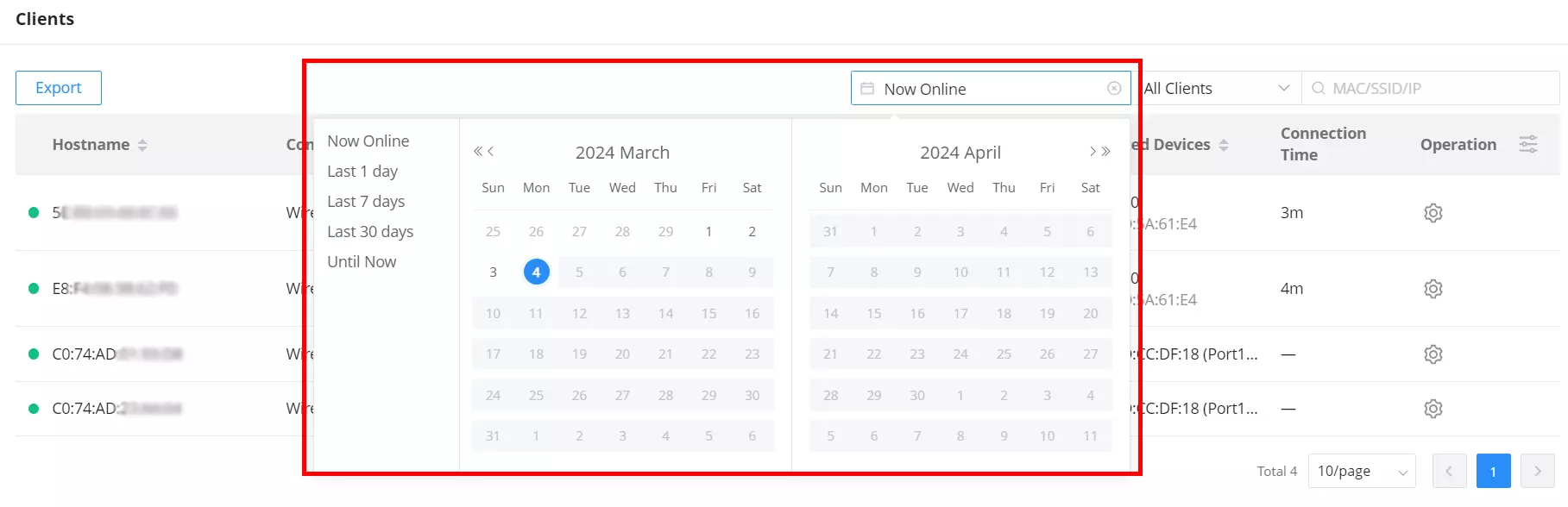
The same way, users can filter clients by wired and wireless connections, they also can filter by time (calendar), many options are available:
- Now Online: displays currently connected clients.
- By day: displays connected clients from a past day selected from the calendar.
- Last 1 day: displays connected clients of the last day.
- Last 7 Days: displays connected clients of the last 7 days.
- Last 30 days: displays connected clients of the last 30 days.
- Until Now: displays all connected clients until the current moment.
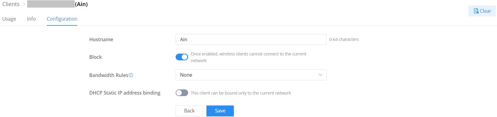
Configure a Client
Per client configuration is available to assign a name or block (only wireless clients) access to the network, also specifying bandwidth rules or enabling DHCP Static address binding.
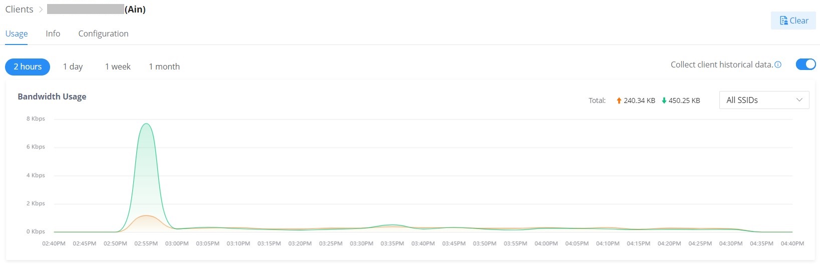
Client usage
To get more info about the client usage please navigate to Web UI → Clients → Usage, Bandwidth usage per SSID, or All SSIDs can be displayed here with the option to specify the duration 2 hours, 1 day, 1 week or 1 month.
Click on ![]() to clear the data.
to clear the data.
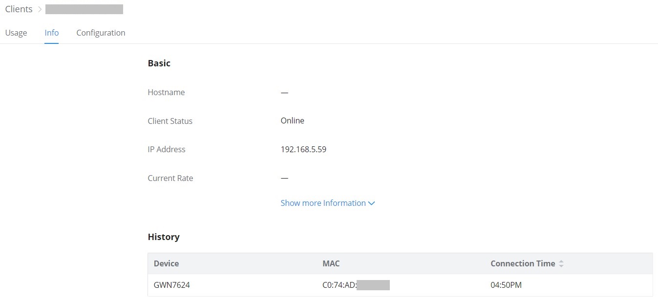
Client info
On this page, info about the current client will displayed showing the client’s Hostname, Client Status, IP Address, Current rate, etc.
Click on “Show more information” to get more info about the client.
GUESTS
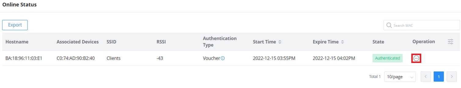
Online Status
This page displays information about the clients connected via the Captive portal including the MAC address, Hostname, Authentication Type, the device they are connected to, Certification state, SSID as well as the RSSI and Data usage.
The administrator can also export a .csv file containing all the guest information (Client MAC address; Authentication Form when choosing Custom Field, Last Visit…etc.) by clicking on the “Export” button, and selecting the export time period for all users which connected to the captive portal during that period.
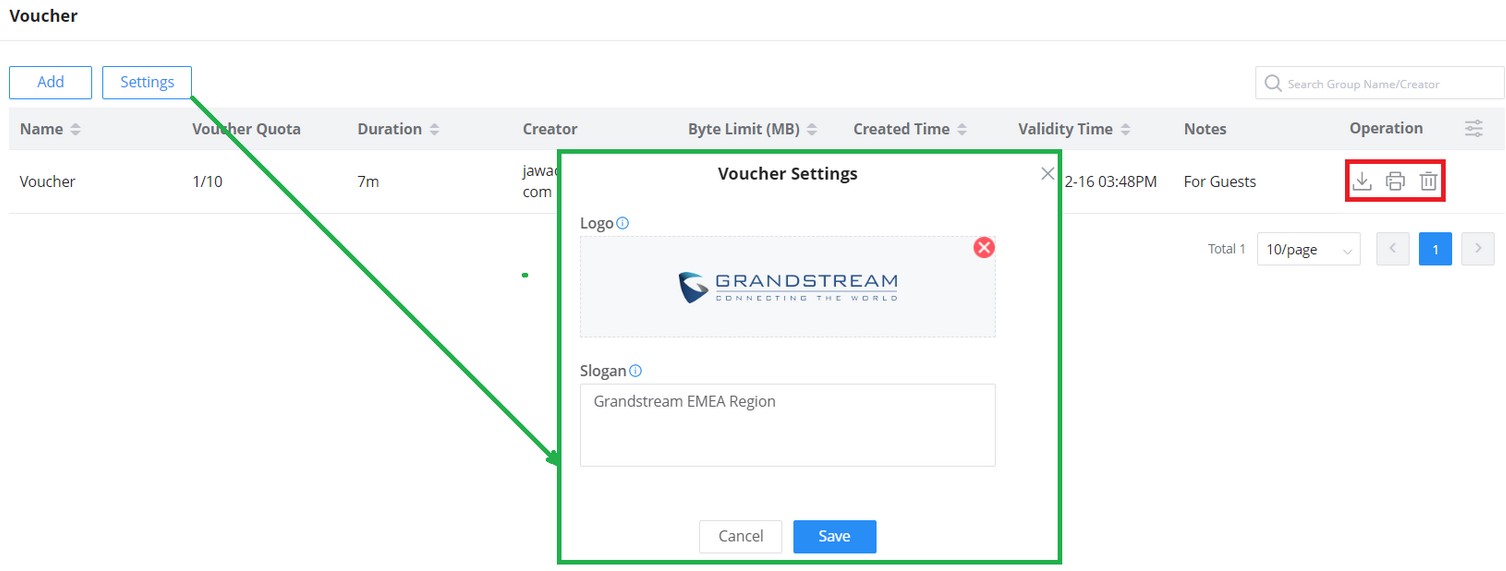
Voucher
The voucher feature will allow clients to have internet access for a limited duration using a code that is randomly generated from the platform controller.
As an example, a coffee shop could offer internet access to customers via Wi-Fi using voucher codes that can be delivered on each command. Once the voucher expires the client can no longer connect to the internet.
Note that multiple users can use a single voucher for connection with the expiration duration of the voucher that starts counting after the first successful connection from one of the users that are allowed.
Another interesting feature is that the admin can set data bandwidth limitations on each created voucher depending on the current load on the network, users’ profile (VIP customers get more speed than regular ones, etc.…), and the internet connection available (fiber, DSL or cable, etc.…) to avoid connection congestion and slowness of the service.
Each created voucher can be printed and served to the customers for usage, and the limit is 1000 vouchers.
Click on ![]() button to add a new voucher.
button to add a new voucher.
MAP & FLOOR PLANS
Map
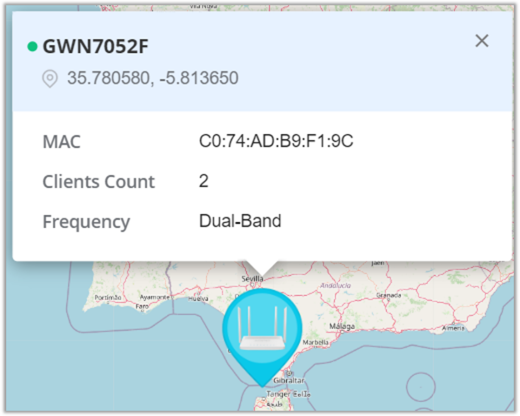
With the Map feature, the administrators can link GWN devices or buildings to certain places on the Map, either manually on the Map or automatically using the device IP address, which will help to geolocate GWN devices or to link them to a different location (ex: company branch).
To place GWN Devices/Building on the Map, please navigate to Web UI → Map & Floor Plans (under Map tab). Please refer to the figure below:
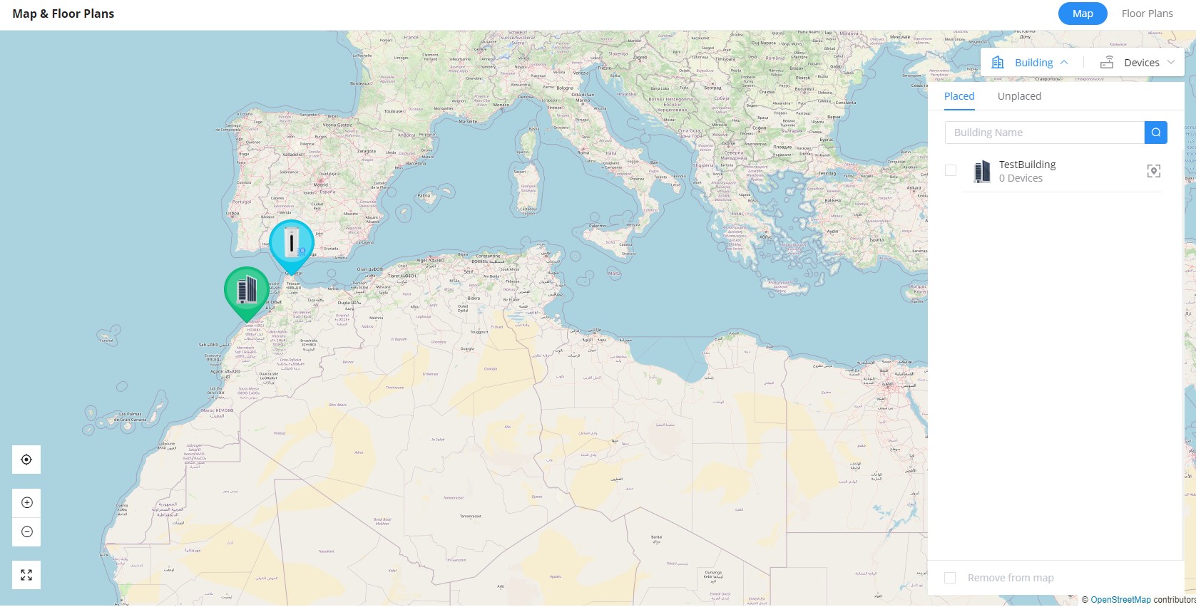
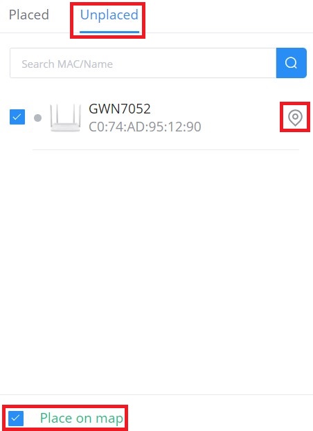
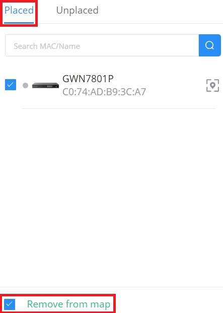
Select “Building” or “Devices” and under “Unplaced” select the device/building then click on the “Map” icon to manually place the GWN device on the map, or click on “Place on map” to be placed based on the IP address.
To remove the GWN device/building from the Map, please select the device/building and then click on “Remove from map“.
Floor Plans
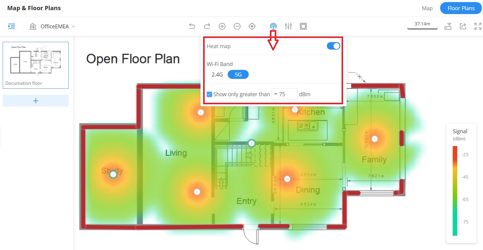
The Floor Plans feature is a very convenient way to deploy devices in the right places within the building this way the wireless signal will be able to cover the area, and an RF heat map preview helps the user to easily predict the best place to deploy a GWN device, and this can be even done using a virtual GWN device like GWN access points or GWN wireless routers. In the case of a large deployment of GWN APs in a building with many walls, Glass, etc., and a large surface area, this feature helps the deployment team to accurately and easily pinpoint the appropriate spots to deploy GWN APs for Wi-Fi signal to cover all the building areas and satisfy the users’ wireless experience.
Please navigate to Web UI → Map & Floor Plans (under Floor Plans tab). Please refer to the figure below:
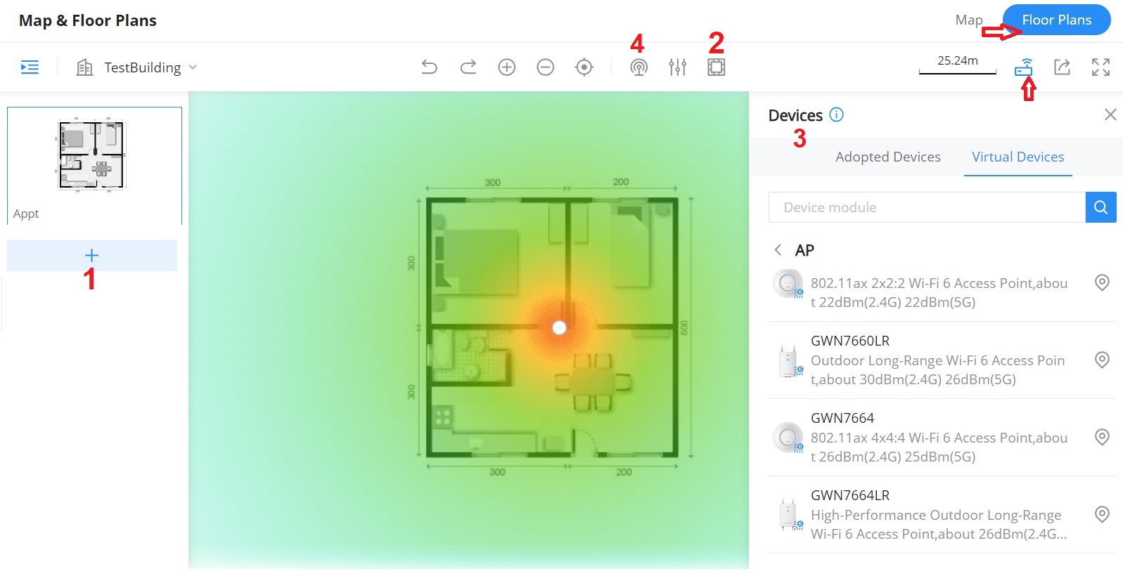
- First, Upload the Floor Plan image by clicking on the “+” icon on the left side of the page.
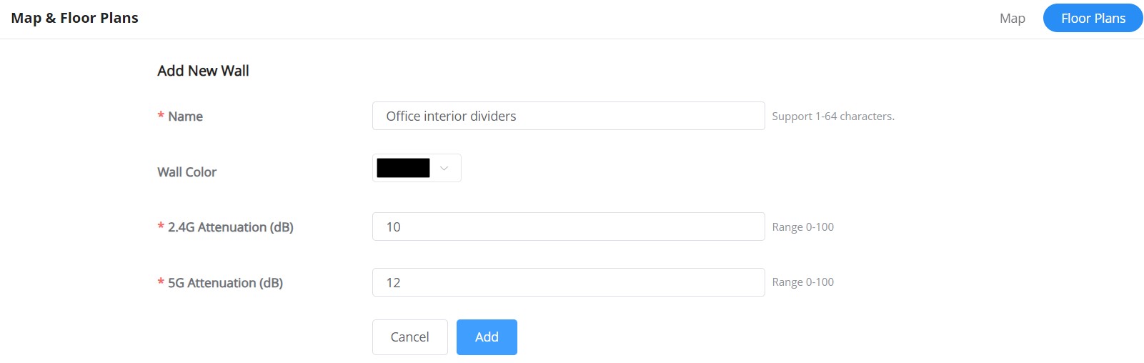
- Then, optionally you can add walls and dividers to the floor plan or click on the “+” button to add a custom wall or divider with 2.4G and 5G attenuation values (dB).
The walls and dividers available are:
- Gypsum Board (8mm) / Foam Sheet (8mm) / Wooden Door (40mm)
Attenuation value: 3dB(2.4G) 4dB(5G) - Glass (8mm); Attenuation value: 4dB(2.4G) 6dB(5G)
- Heavy Sheet Glass (12mm); Attenuation value: 8dB(2.4G) 10dB(5G)
- Brick Wall (120mm) / Solid Wood Door (40mm); Attenuation value: 10dB(2.4G) 15dB(5G)
- Thick Brick Wall (240mm); Attenuation value: 15dB(2.4G) 25dB(5G)
- Concrete (240mm); Attenuation value: 25dB(2.4G) 30dB(5G)
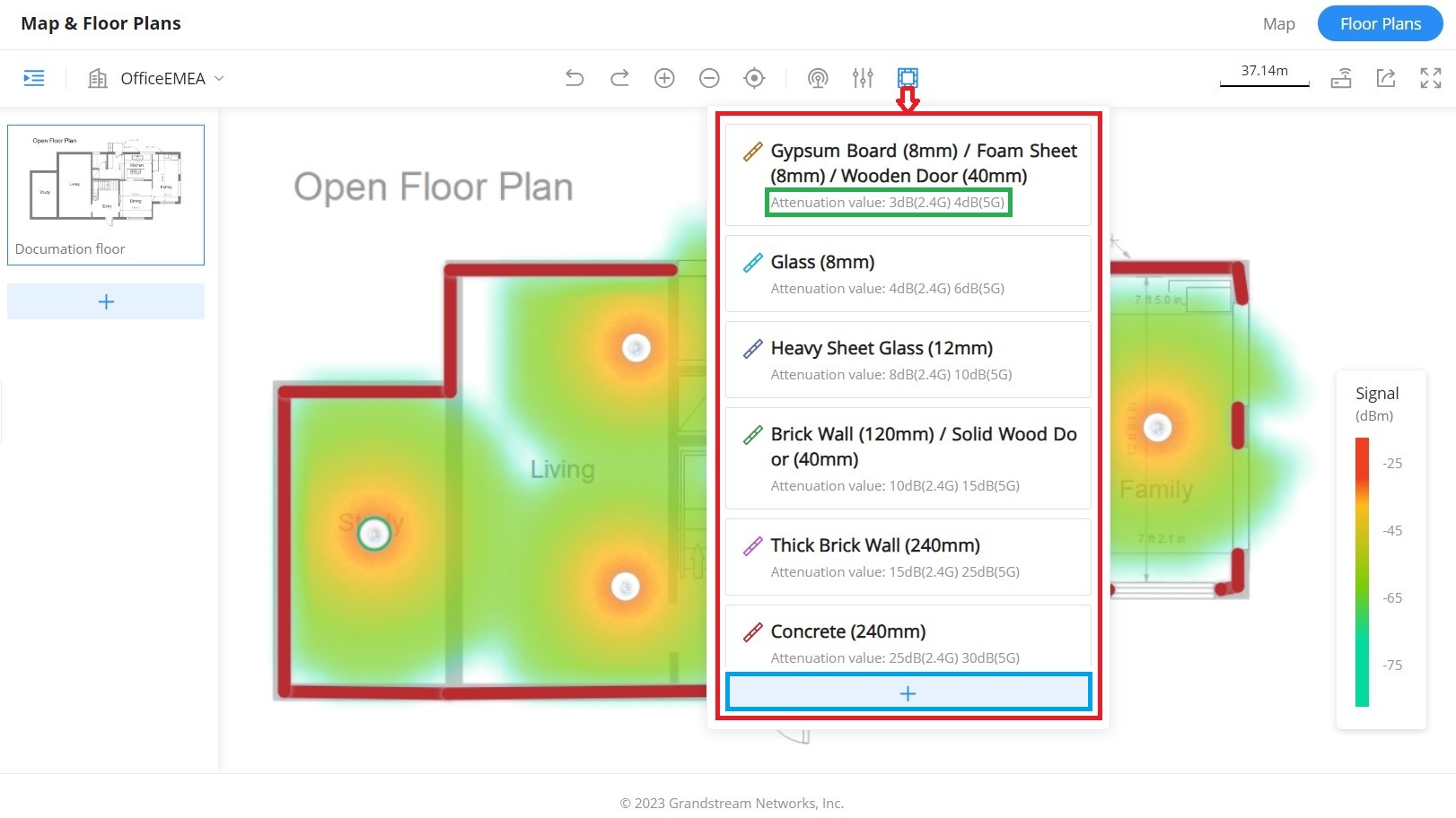
Click on the “+” button as shown above to add a custom wall or a divider.
- Under devices, please select the GWN device either from adopted ones or virtual ones then place it on the floor building accordingly.
- Finally, click on the “Heat Map” icon and select either 2.4G or 5G wireless signal to be able to see the full range of the wireless signal. Also, it’s possible to show only signals greater than the specified dBm, this way the user can hide the weak signal from the heat map.
INSIGHTS
Site Survey
An integrated Wi-Fi Scanner is supported on GWN Management Platforms to help the administrator scan the wireless networks in the area and to display extensive information including SSID’s name, AP’s MAC address, Channel used, Wi-Fi Standard, Bandwidth, security standard used, Manufacturer, RSSI, … and more.
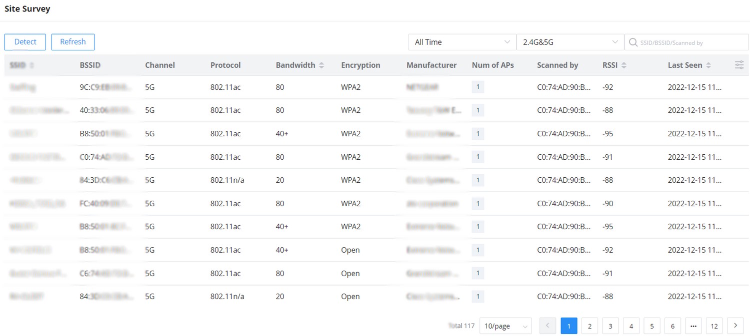
Users can press the “Detect” button to run the Wi-Fi scanner or press the “Refresh” button to refresh the results page.
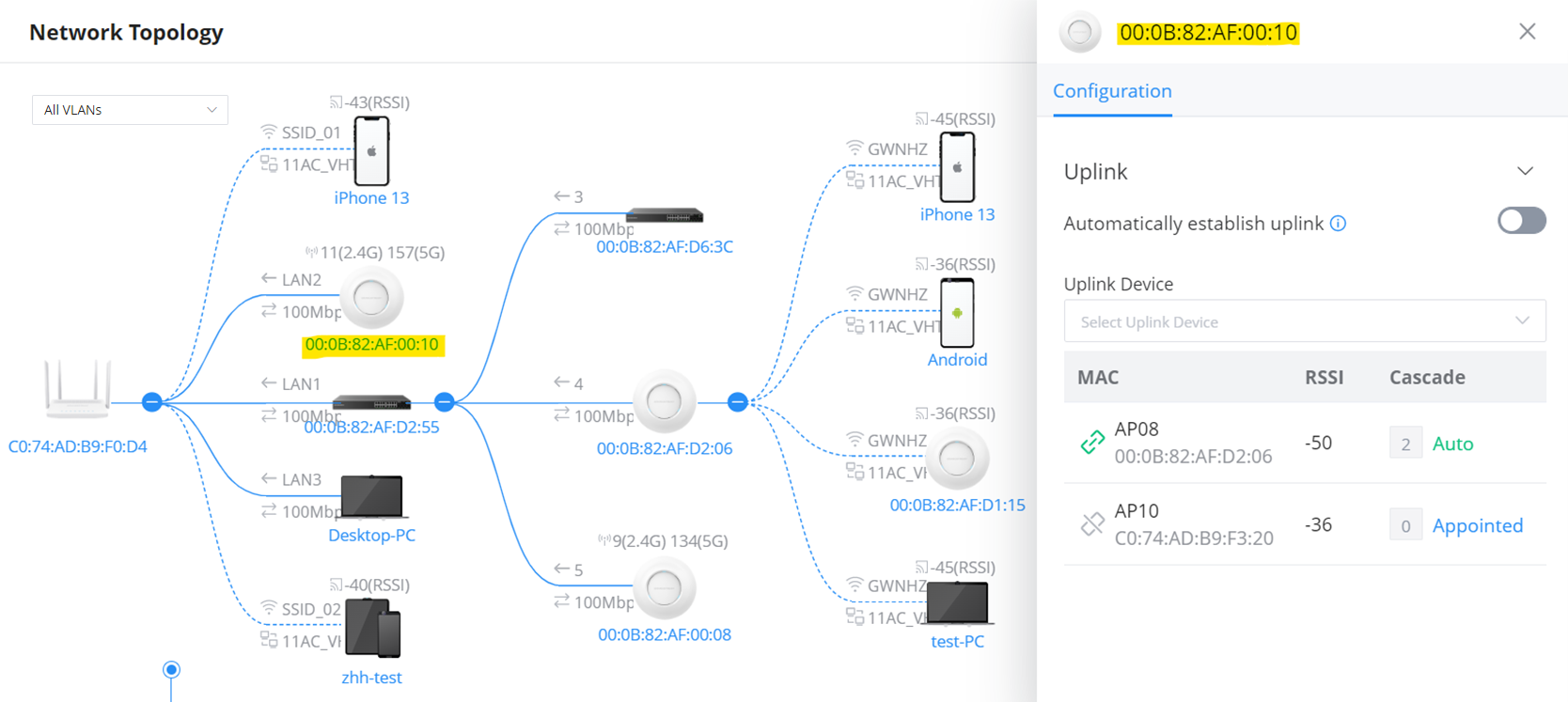
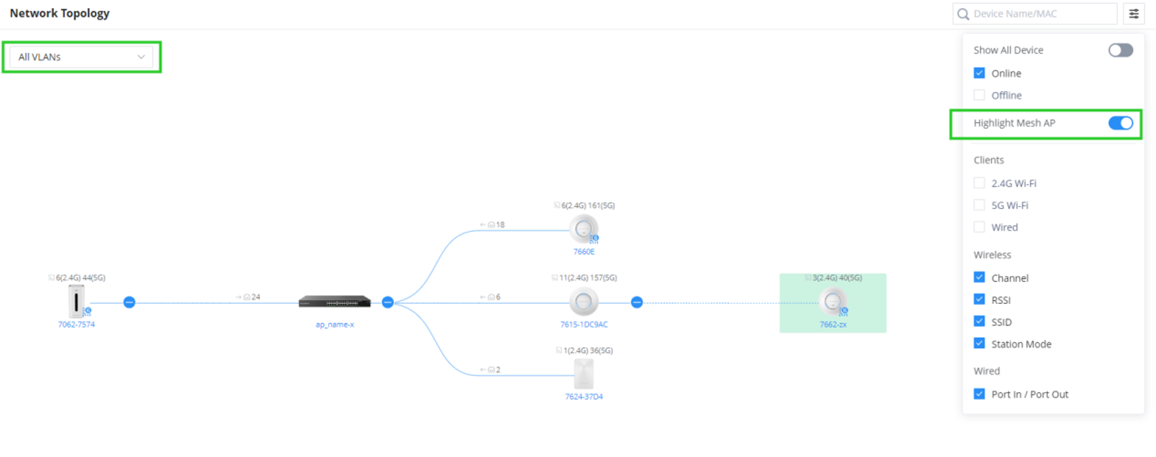
Network Topology
Network Topology shows an overview of the whole network starting from the GWN Router (Internet access) including GWN Switches and Access Points as well as Clients, this way the administrator/monitor can have very quickly an overview of the network at a glance. By clicking on a GWN device or a Client more information can be displayed.
Features overview:
- Display network layout
- Visualize gateway, switch, access point, and connected client device information
- The topology map can be zoomed in, and out, and nodes are retractable
- Support Mesh AP and also the option to Highlight Mesh AP
- VLAN information filtering
Notes:
- Click on
 to collapse that part of the network.
 - Dashed lines mean wireless connection while solid lines mean wired connection.
To backup the current topology or share it, on the top right corner of the page, click on the “Export” button, and a PNG image will be downloaded.

ALERTS
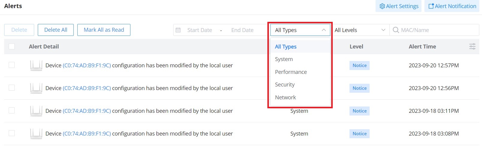
The Alerts page displays alerts about the network, the user can specify to display only certain types like (System, Performance, Security, or Network) or the levels. To check the alerts that have been generated, please navigate to the Web UI → Alerts page.
The alerts can be displayed either by type or level. However, that is not the only way to display them. The user can filter through the alert log using a date interval or search by MAC address or device name.
- Alert Types
The available types are System, Performance, Security, and Network, or the user can choose to display all the types.
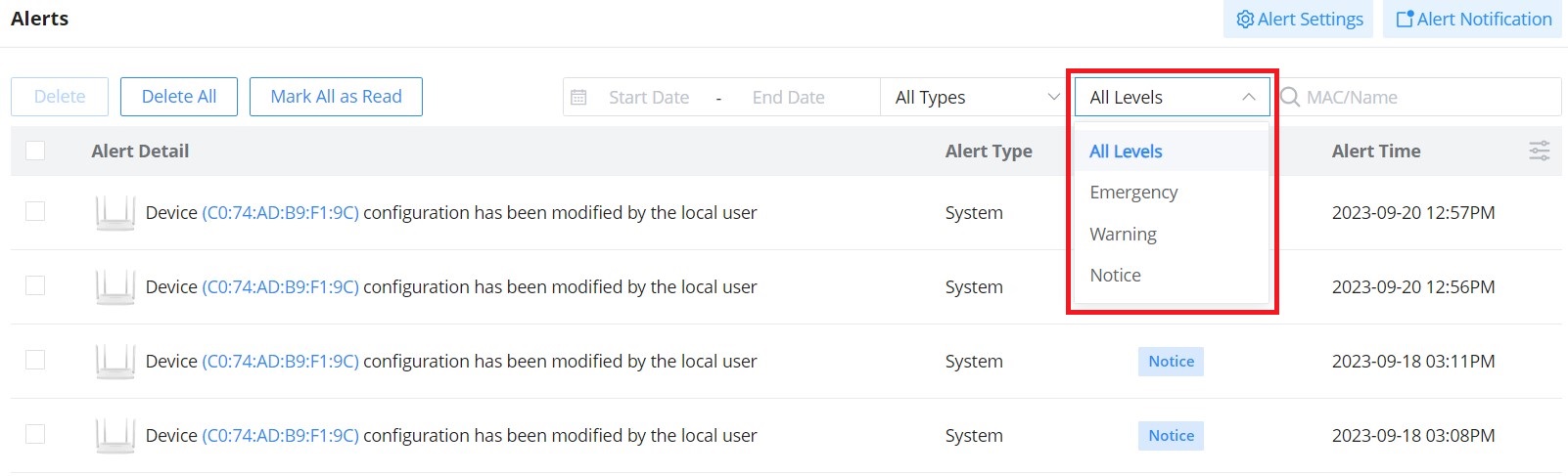
- Alert Levels
The user can filter the alert level by the following levels: All Levels, Emergency, Warning or Notice.
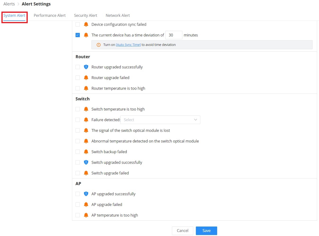
Alert Settings
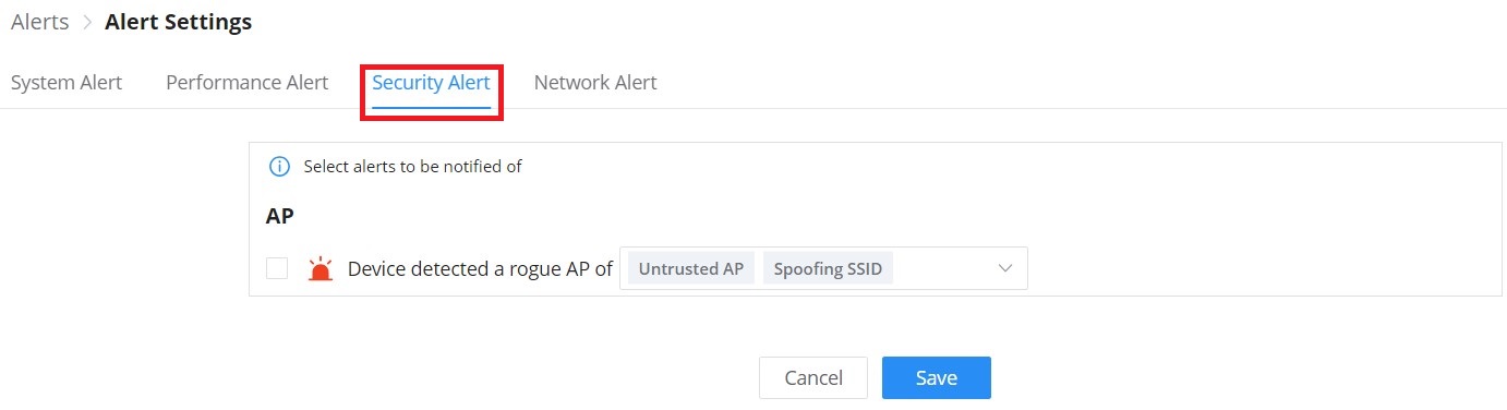
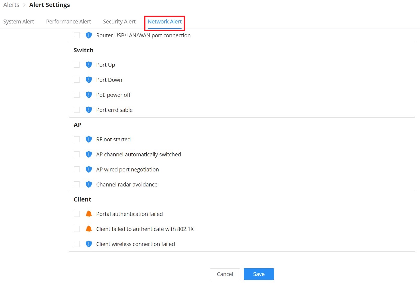
On this page the user can select the alerts to be displayed, four categories or alerts are available (system, performance, security, and network) and each category has even more options. Please check the figures below:
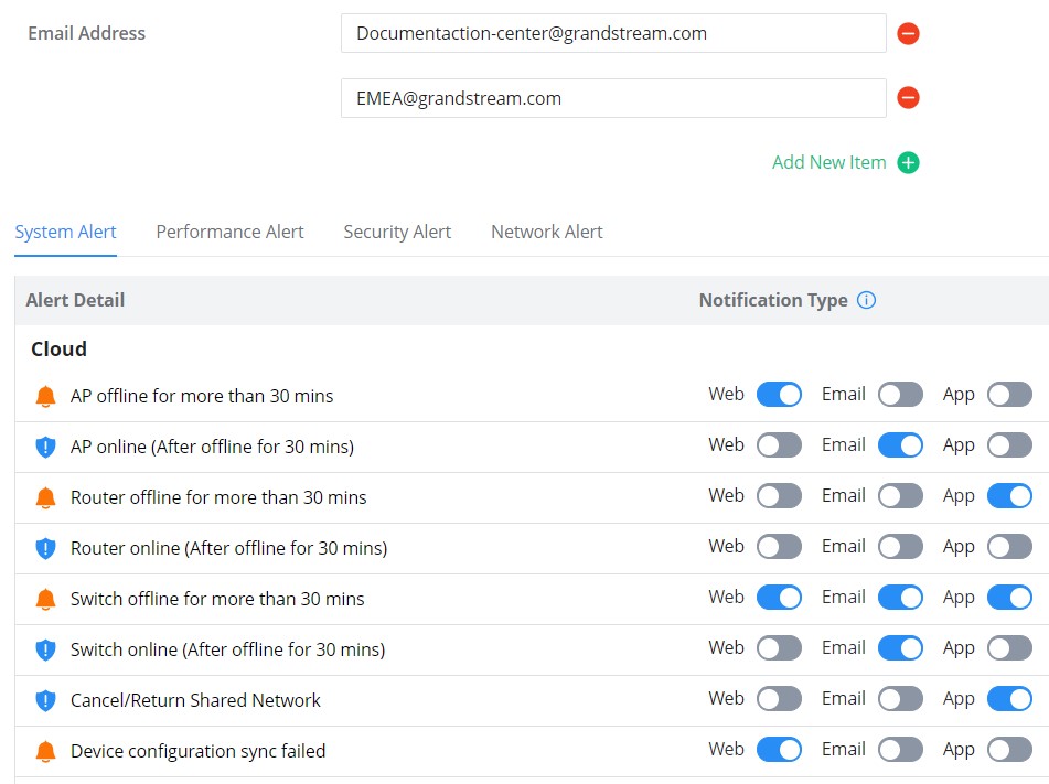
- System Alert includes GWN.Cloud/GWN Manager, GWN Routers, GWN Switches, and GWN Access points.
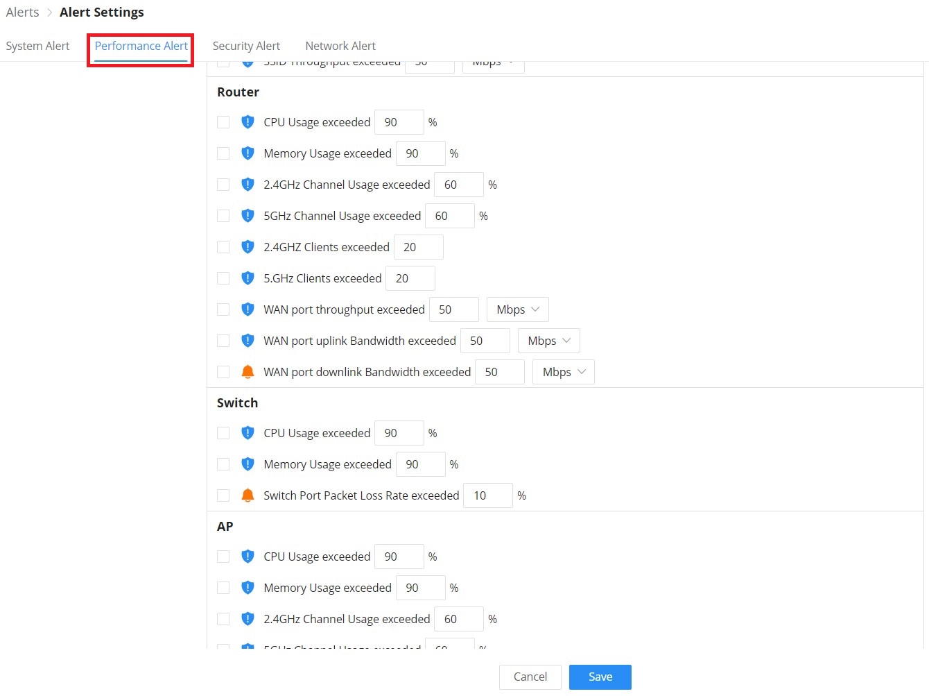
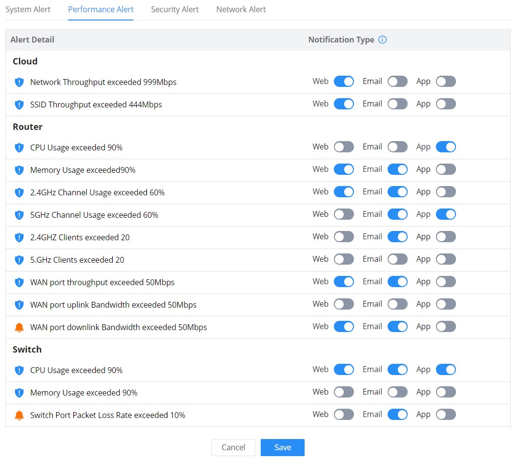
- Performance Alert includes GWN.Cloud/GWN Manager, GWN Routers, GWN Switches, and GWN Access points.
- Security Alert: GWN Access points (Rogue AP).
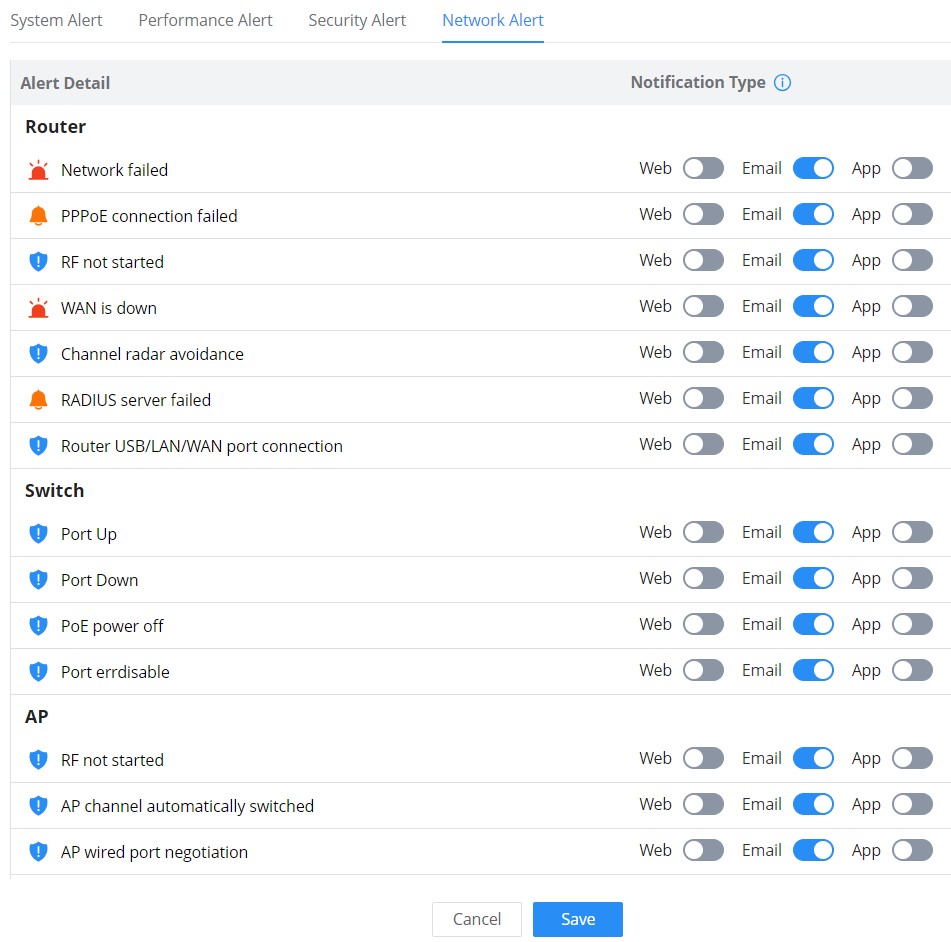
- Network Alert includes GWN Routers, GWN Switches, GWN Access points, and Clients.
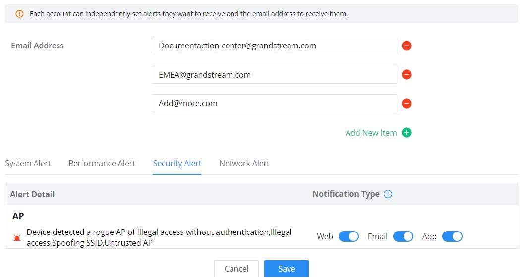
Alert Notification
On this page, Email addresses can be specified to receive notifications for the selected alerts, the notifications can be sent to the configured emails, web, or App.
SETTINGS
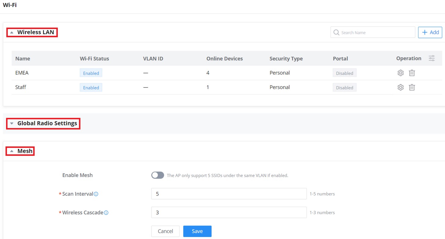
Wi-Fi
All the related settings about Wi-Fi can be found on this page, split into 2 sections Wireless LAN, Global Radio Settings, and Mesh.
Wireless LAN
Under the Wireless LAN section, SSIDs will displayed with Wi-Fi Status and Online Devices, etc. for configuration click on the SSID or configuration icon.
the user can also click on ![]() button to add a new SSID, the configuration can be only specific to this SSID, to configure radios for all SSIDs please click on section two “Global Radio Settings”.
button to add a new SSID, the configuration can be only specific to this SSID, to configure radios for all SSIDs please click on section two “Global Radio Settings”.
Add SSID
To add a new SSID, navigate to Web UI → Settings → Wi-Fi page → Wireless LAN section then click the “Add” button. A new page will pop up, enter different settings to add a new SSID.
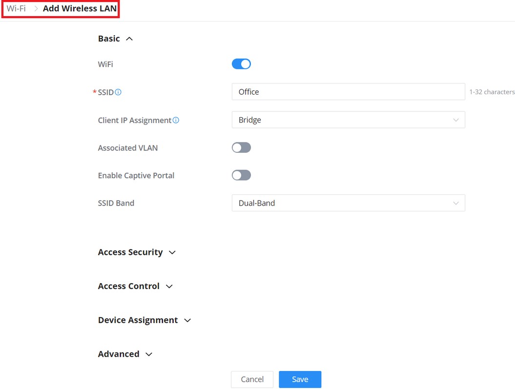
Basic | |
WiFi | Check to enable Wi-Fi for the SSID |
SSID | Set or modify the SSID name. |
Client IP Assignment | Select between Bridge or NAT |
Associated VLAN | Check to Enable VLAN and enter VLAN ID, otherwise, this SSID will be using the default network group. |
Enable Captive Portal | Click on the checkbox to enable the captive portal feature. |
SSID Band | Select the Wi-Fi band the GWN will use, three options are available: |
Access Security | |
Security Type | Set the security type, 5 options are available:
|
802.11w | Disabled:disable 802.11w; Optional: either 802.11w supported or unsupported clients can access the network; Required: only the clients that support 802.11w can access the network. |
Access Control | |
MAC Filter | Choose Blacklist/Whitelist to specify MAC addresses to be excluded/included from connecting to Wi-Fi. Default is Disabled. |
Client Isolation | Client isolation feature blocks any TCP/IP connection between connected clients to GWN76xx’s Wi-Fi access point. Client isolation can be helpful to increase security for Guest networks/Public Wi-Fi. Available modes are:
|
Client Time Policy | Configures the client time policy. Default is None. |
Bandwidth Control | Select Bandwidth Control (Per-SSID or Per-Client), then select from the Bandwidth rules previously created. |
Schedule | Select a schedule that will be applied to this SSID, schedules can be managed from the menu “Settings → Profiles → Schedule”. |
OS Filter | Whitelist or blacklist clients based on what OS they are using.
Warning: This feature requires certain client functionality to work, and some clients' OS may not be supported. |
OS Whitelist/Blacklist | Note: this option is only availabe if OS Filter is enabled. Select one or more or All from the list below:
|
Device Assignment | |
Select from the Devices list the ones to be part of this SSID. Note: If an AP or router that uses the Wi-Fi network is selected, new APs will be automatically added to the network. | |
Advanced | |
SSID Hidden | Select to hide SSID. SSID will not be visible when scanning for Wi-Fi, to connect a device to hidden SSID, users need to specify SSID name and authentication password manually. |
DTIM Period | Configures the frequency of DTIM (Delivery Traffic Indication Message) transmission per each beacon broadcast. Clients will check the AP for buffered data at every configured DTIM Period. You may set a high value for power saving consideration. |
Wireless Client Limit | Configure the limit for wireless client. If there’s an SSID per-radio on a network group, each SSID will have the same limit. So, setting a limit of 50 will limit each SSID to 50 users independently. 0 means limit is disabled. |
Client Inactivity Timeout | AP will remove the client’s entry if the client generates no traffic at all for the specified time period. The client inactivity timeout is set to 300 seconds by default. |
Multicast/Broadcast Suppression | Disable: all of the broadcast and multicast packages will be forwarded to the wireless interface. Enable: all of the broadcast and multicast packages will be discarded except DHCP/ARP/IGMP/ND; Enable with Proxy ARP enabled: enable the optimization with Proxy ARP enabled in the meantime. |
Convert IP multicast to unicast | Once selected, AP will convert multicast streams into unicast streams over the wireless link. Which helps to enhance the quality and reliability of video/audio stream and preserve the bandwidth available to the non-video/audio clients. |
Enable Voice Enterprise | Enable this feature to help clients connected to the GWN76xx to perform better roaming decision.
Note: 11R is required for enterprise audio feature, 11V and 11K are optional. Enable Voice Enterprise is only available under "WPA/WPA2" and "WPA2" Security Mode. |
Enable 802.11r | Check to enable 802.11r |
Enable 802.11k | Check to enable 802.11k |
Enable 802.11v | Check to enable 802.11v |
ARP Proxy | Once enabled, AP will avoid transferring the ARP messages to Stations, while initiatively answer the ARP requests in the LAN. |
Enable Bonjour Gateway | Click to enable Bonjour Gateway Note: If enabled, client Bonjour requests on SSID can be forwarded to the VLAN of Bonjour services (such as Samba). |
Enable U-APSD | Configures whether to enable U-APSD (Unscheduled Automatic Power Save Delivery) |
Add Wireless LAN
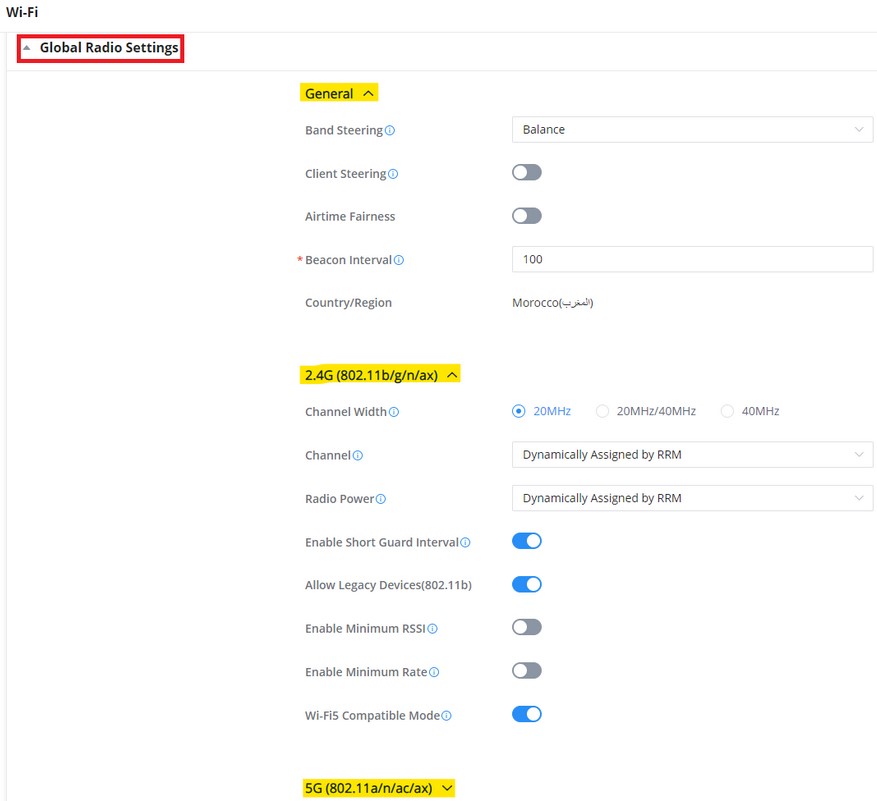
Global Radio Settings
On this page the Administrator can configure the global radio settings which will affect all the GWN devices with the wireless signal, it’s a convenient way to configure all the device’s wireless signal at once.
To configure a specific device (GWN AP or Wireless GWN router), navigate to Web UI → Devices, then click on the device or the configuration icon then select the Configuration Tab. Refer to the figure below:
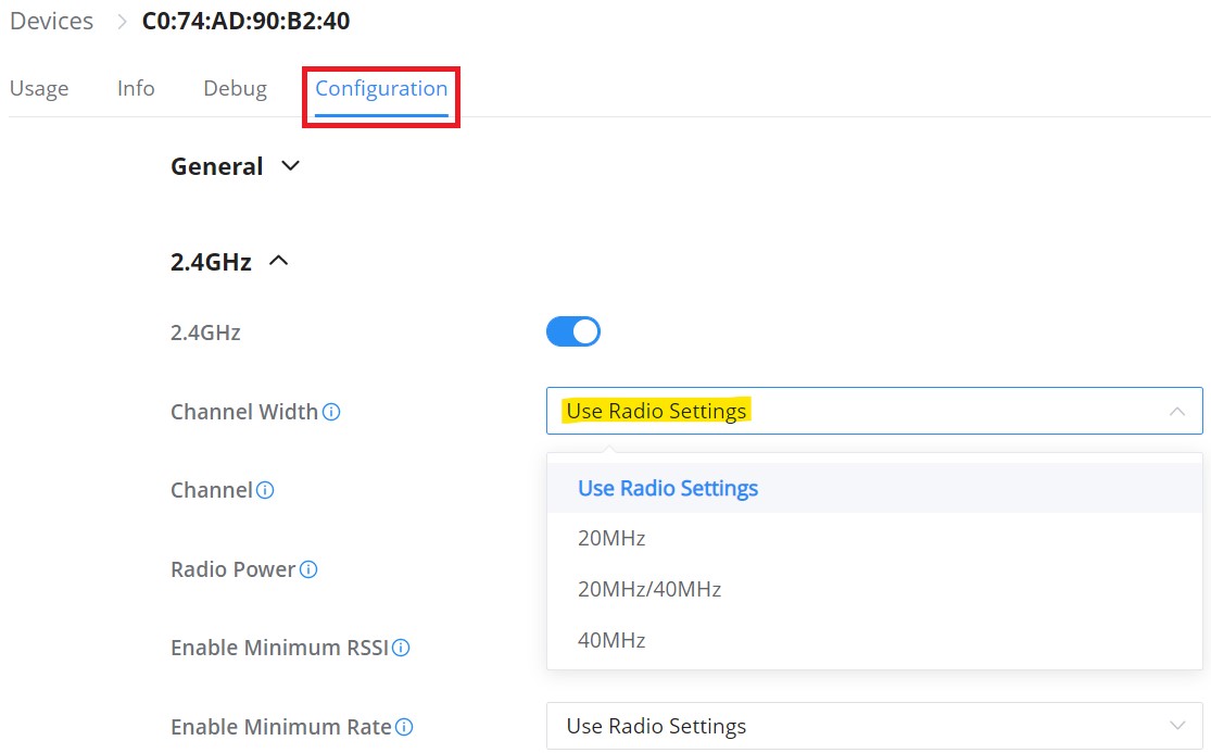
Selecting the option “Use Radio Settings” from the drop-down list will use the settings configured on the Global Radio Settings section.
Please refer to the table below:
General | |
Band Steering | Select from the drop-down list, four options are available:
|
Client Steering | This feature will help Wi-Fi client to roam to other APs within same Network. Steering happens when clients is inactive or active clients with the standards 802.11K&V support. |
RSSI Threshold | It will start monitoring the RSSI for the clients in order to redirect them to another GWN AP in the same network. This prevents clients from remaining associated with AP with less than ideal RSSI, which can cause poor connectivity and reduce performance for other clients. Default is -75. |
Client Access Threshold | It will start monitoring the number of clients’ connections with the AP, once reaching configured threshold, it will roam to the other. Default is 30. |
Airtime Fairness | Allows faster clients to have more airtime than slower clients. |
Beacon Interval | Configures interval between beacon transmissions/broadcasts.
Notes:
Default value is 100ms. Valid range: 40 – 500 ms. |
Country/Region | Displays the country/region of the AP. |
2.4G/5G | |
Channel Width | Choose the Channel Width, note that wide channel will give better speed/throughput, and narrow channel will have less interference. 20MHz is suggested in very high-density environment. |
Channel | Select “Auto” or a Dynamically Assigned by RRM. Default is “Auto”. |
Custom Channel | Select a custom channels. Note: that the proposed channels depend on Country Settings under Settings → System. |
Radio Power | Set the Radio Power, it can be Low, Medium, or High or Custom or Dynamically assigned by RRM or Auto. Note : Dynamically assigned by RRM activates TPC and CHD:
Custom: allows users to set a custom wireless power for both 5GHz/2.4GHz band, the value of this field must be between 1 and 31. |
Enable Short Guard Interval | Check to activate this option to increase throughput. |
Allow Legacy Devices (802.11b) | Check to support 802.11b devices to connect the AP in 802.11n/g mode. (2.4GHz setting) |
Enable Minimum RSSI | Check to enable RSSI function, this will lead the AP to disconnect users below the configured threshold in Minimum RSSI (dBm). |
Minimum RSSI (dBm) | Enter the minimum RSSI value in dBm. If the signal value is lower than the configured minimum value, the client will be disconnected. The input range is from “-94” or “-1”. |
Enable Minimum Rate | Specify whether to limit the minimum access rate for clients. This function may guarantee the connection quality between clients and AP. |
Minimum Rate (Mbps) | Specify the minimum access rate. Once the client access rate is less than the specified value, AP will kick it off. Available values are: 1Mbps, 2Mbps, 5Mbps, 6Mbps, 9Mbps, 11Mbps or 12Mbps. |
Wi-Fi5 Compatible Mode | Some old devices do not support Wi-Fi6 well and may not be able to scan the signal or connect poorly. After turning on this switch, it will switch to Wi-Fi5 mode to solve the compatibility problem. At the same time, it will turn off Wi-Fi6 related functions. |
Global Radio Settings
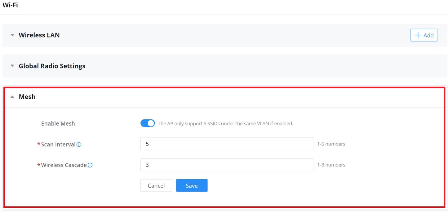
Mesh
Wireless Mesh Network is a wireless extension of the traditional wired network using multiple access points connected through wireless links to areas where wired access is not an option while also expanding the coverage of the WLAN network.
In the traditional WLAN network, the uplink of the AP is a wired network (usually an Ethernet Link):
- The advantages of a wired network are security, anti-interference, and stable bandwidth.
- The disadvantages are high construction cost, long periods of planning and deployment, and difficulty of change in case a modification is needed.
However, these are precisely the advantages of wireless networks. As a result, a Wireless Mesh Network is an effective complement to wired network.
In addition, Mesh networking provides a mechanism for network redundancy. When an abnormality occurs in a wired network, an AP suffering the uplink failure can keep the data service continuity through its Mesh network.
For more details about the GWN Mesh Network feature, please don’t hesitate to read the following technical paper:
Users can set some Mesh Network parameters under the menu “Settings → Wi-Fi → Mesh”, as shown in the figure below:
LAN
This page shows all the created VLANs as well as the Default VLAN (Default LAN), as well as the global switch settings that affect all the added GWN switches.
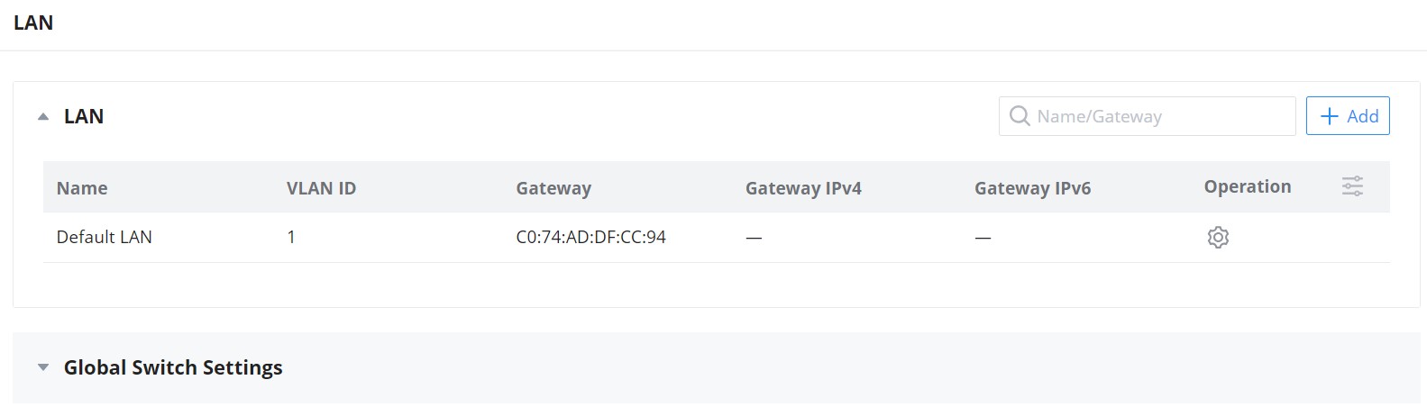
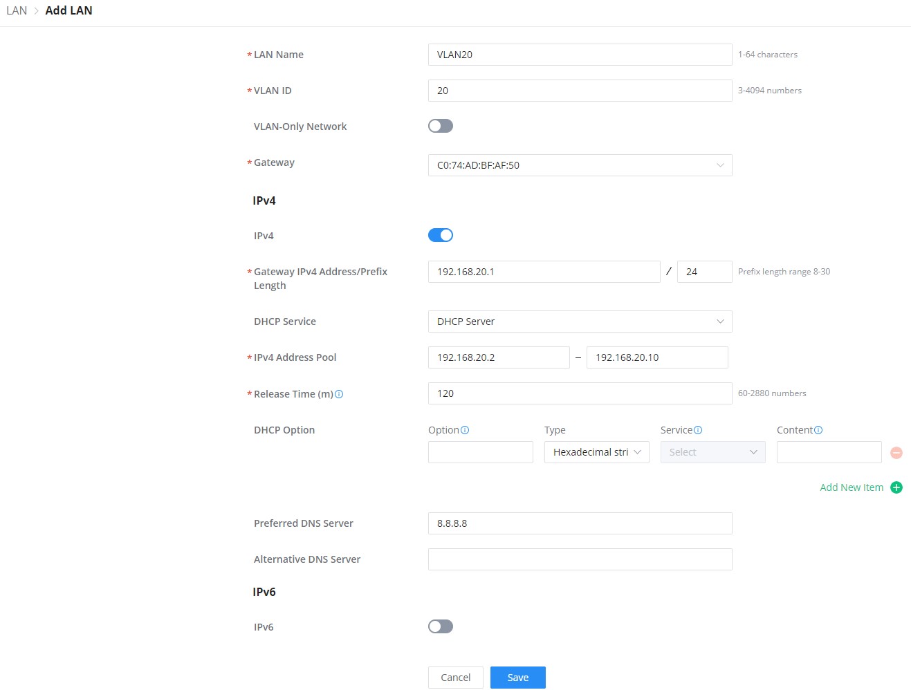
The user can click on ![]() button to add a LAN/VLAN, then specify the name, VLAN ID, Gateway, and IPv4/IPv6.
button to add a LAN/VLAN, then specify the name, VLAN ID, Gateway, and IPv4/IPv6.
Global Switch Settings
Global Switch Settings allow the user to configure the general settings for all the GWN78XX switches which have been added to the account, instead of configuring the settings individually for each switch.
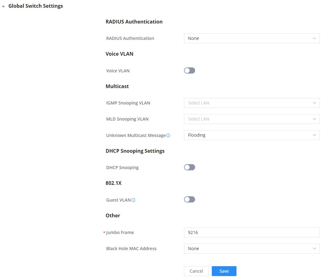
Radius Authentication | |
Radius Authentication | Select a Radius server or click Add New RADIUS |
Voice VLAN | |
Voice VLAN | Toggle voice VLAN on/off. |
Multicast | |
IGMP Snooping VLAN | Select the IGMP Snooping VLAN. |
MLD Snooping VLAN | Select the MLD Snooping VLAN. |
Unknown Multicast Message | Configures how the switch (IGMP Snooping/MLD Snooping) handles packets from unknown groups. |
DHCP Snooping Settings | |
DHCP Snooping | Toggle DHCP Snooping on/off |
802.1X | |
Guest VLAN | Configures whether to enable the guest VLAN function for the global port. |
Other | |
Jumbo Frame | Enter the size of the jumbo frame. Range: 1518-10000 |
Black Hole MAC Address | Select a Black Hole MAC Address from the list or click Add New MAC group |
Internet
Internet configurations like adding/configuring WAN ports or configuring Load-balancing/backup (Failover) between the WANs port are found here, please navigate to Web UI → Settings → Internet page.
WAN
In this section, the user can add WAN (router WAN port or a device group) or edit previously created WAN ports, and the number of WAN ports is determined by how many GWN routers are added/adopted to GWN.Cloud/GWN Manager accordingly. Once, the WAN/Device group is added, then the user can monitor the network health for the last 12 hours.
Please navigate to Web UI → Settings → Internet page → WAN section.
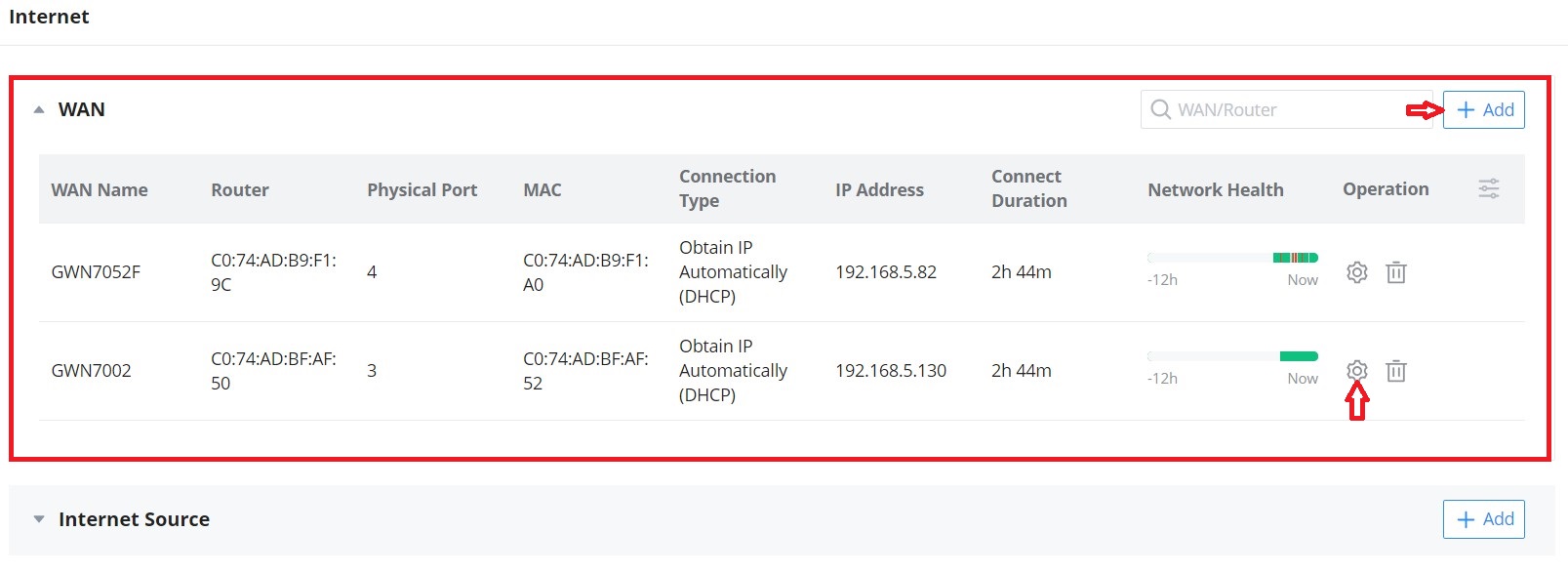
- Network Health
Network Health is a feature that monitors the WAN (WAN ports or Device group) and displays the status for the last 12 hours for each WAN/device group with color code.
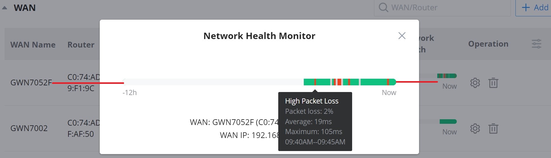
Hover with the cursor over the color to see more details like Packet loss percentage, duration etc.
Green: Online
Grey: Offline
Red: High Packets Loss
- Add or Edit a WAN/Device group
To edit a WAN click on the entry or click on the “Configure icon” under operation, and to add a WAN click on the “Add” button on the top of the page. on the next page, the user can configure the WAN name, router (WAN port or logical device group), physical port, connection type (DHCP, Static or PPPoE), MTU, DDNS, DMZ, UPnP, etc. Please check the figures and table below:
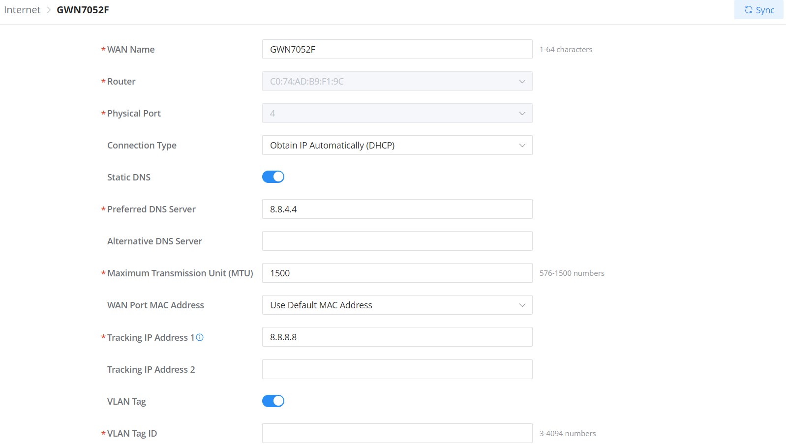
WAN Name | Specify a name for the WAN |
Router | Select a router or a Device group from the drop-down list |
Physical Port | Select the physical port (WAN port) from the drop-down list |
Connection Type |
The default setting is “Obtain IP automatically (DHCP)” |
Static DNS | Check Static DNS then enter the Preferred DNS Server and the Alternative DNS Server |
Preferred DNS Server | Enter the preferred DNS Server |
Alternative DNS Server | Enter the Alternative DNS Server |
Maximum Transmission Unit (MTU) | Configures the maximum transmission unit allowed on the WAN.
|
WAN Port MAC Address | Select from the drop-down list either to:
Default is "Use Default MAC Address" |
Custom MAC Address | Enter the custom MAC Address to be used with this WAN. |
Tracking IP Address 1 | Configures tracking IP address of WAN port to determine whether the WAN port network is normal. |
Tracking IP Address 2 | Add another alternative address for Tracking IP Address |
VLAN Tag | Select if either to enable or disable VLAN Tag. |
VLAN Tag ID | Enter the VLAN tag ID. |
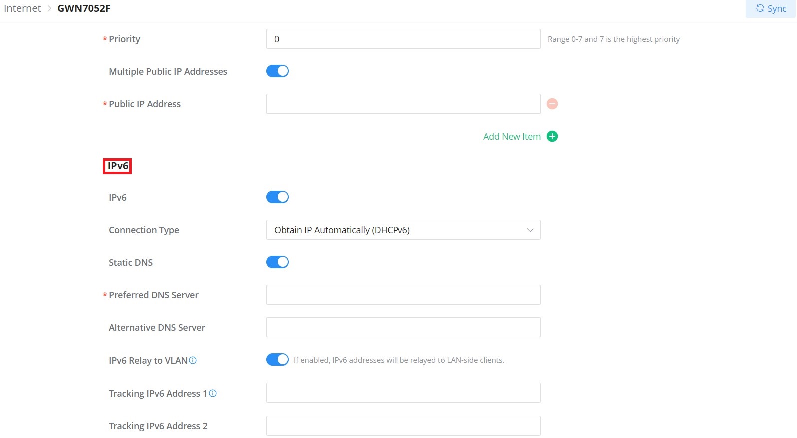
Priority | Enter the priority Note: Range 0-7 and 7 is the highest priority |
Multiple Public IP Addresses | Please use with Port Forward function, so that you can access to router via public IP address. |
Public IP Address | Enter one or more public IP addresses Click on "+" icon or "-" icon to add or delete public IP addresses |
IPv6 | |
IPv6 | Enable this option to use IPv6 on this specific WAN. |
Connection Type | Select the connection type fromt the drop-list, three options are available:
The default setting is “Obtain IP automatically (DHCPv6)”. |
Static DNS | Enable this option to enter statically assigned DNS |
Preferred DNS Server | Enter the preferred DNS Server |
Alternative DNS Server | Enter the Alternative DNS Server |
IPv6 Relay to VLAN | Once enabled, relay IPv6 addresses to clients on the LAN side. Note: This function will take effect only "IPv6 Relay from WAN" is enabled on VLAN. |
Tracking IPv6 Address 1 | Configures tracking IP address of WAN port to determine whether the WAN port network is normal |
Tracking IPv6 Address 2 | Add another alternative address for Tracking IP Address |
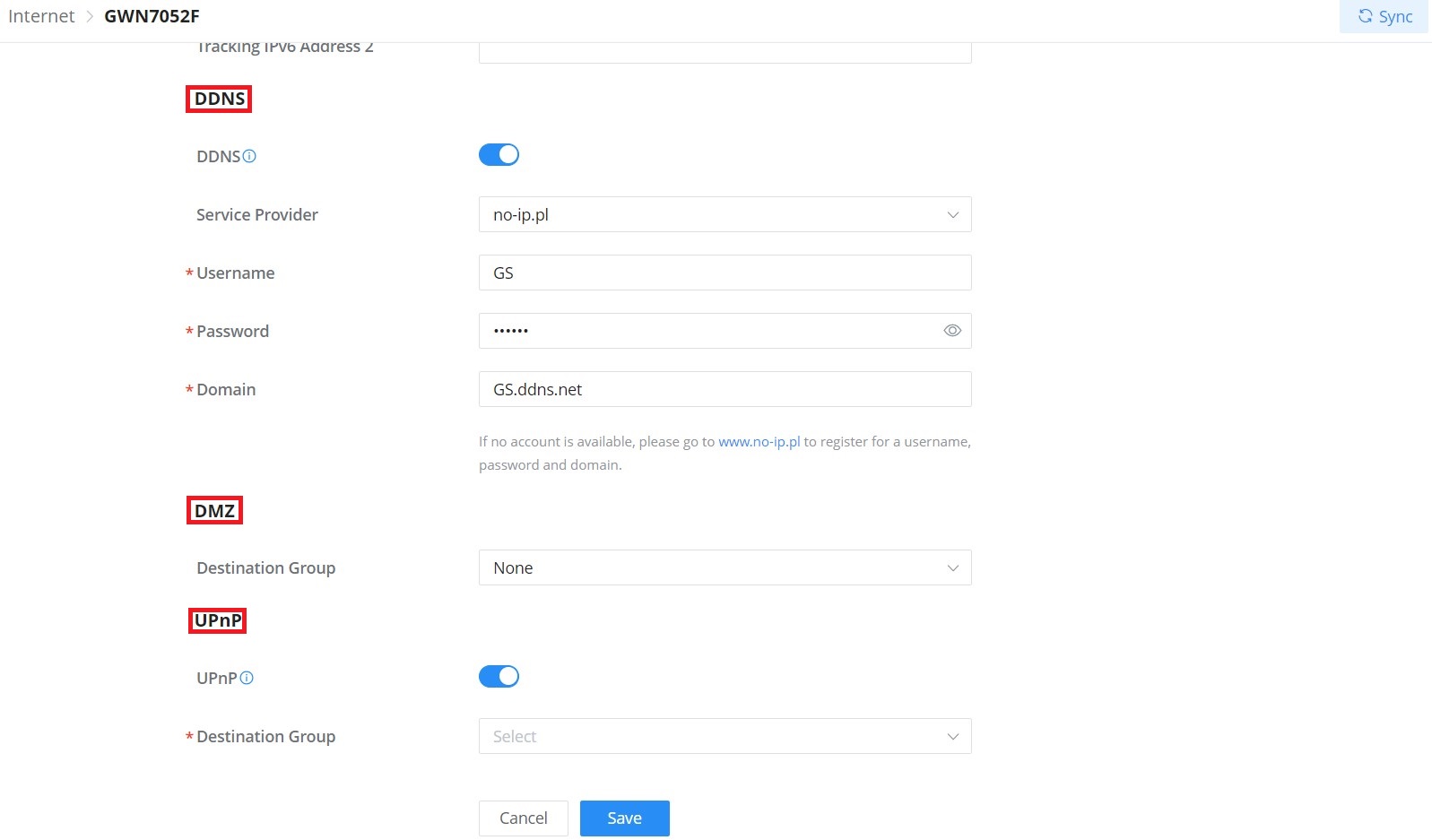
DDNS | |
DDNS | Toggle ON or OFF the DDNS function, default is OFF Note: On the router, DDNS function can only be enabled on one WAN port |
Service Provider | Select the DDNS provider from the list Note: If no account is available, please go to www.oray.com to register for a username, password and domain |
Username | Enter the Username |
Password | Enter the Password |
Domain | Enter the Domain |
DMZ | |
Destination Group | Select the destination group from the drop-down list. |
UPnP | |
UPnP | Toggle ON or OFF the UPnP function, default is OFF Note: If UPnP (Universal Plug and Play) is enabled, devices on LAN can request the router to port forward automatically |
Destination Group | Select the destination group from the drop-down list. |
Add/edit a WAN
Internet Source
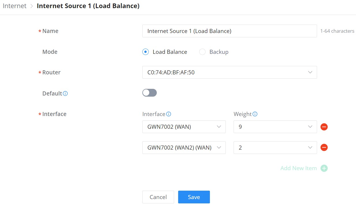
In this section of internet configuration, under internet source, the user can configure load balancing or backup (Failover) between the previously added WANs. Either click on the entry or “Configure icon” to edit previously added internet sources or click on the “Add” button to add a new one, refer to the figure below:
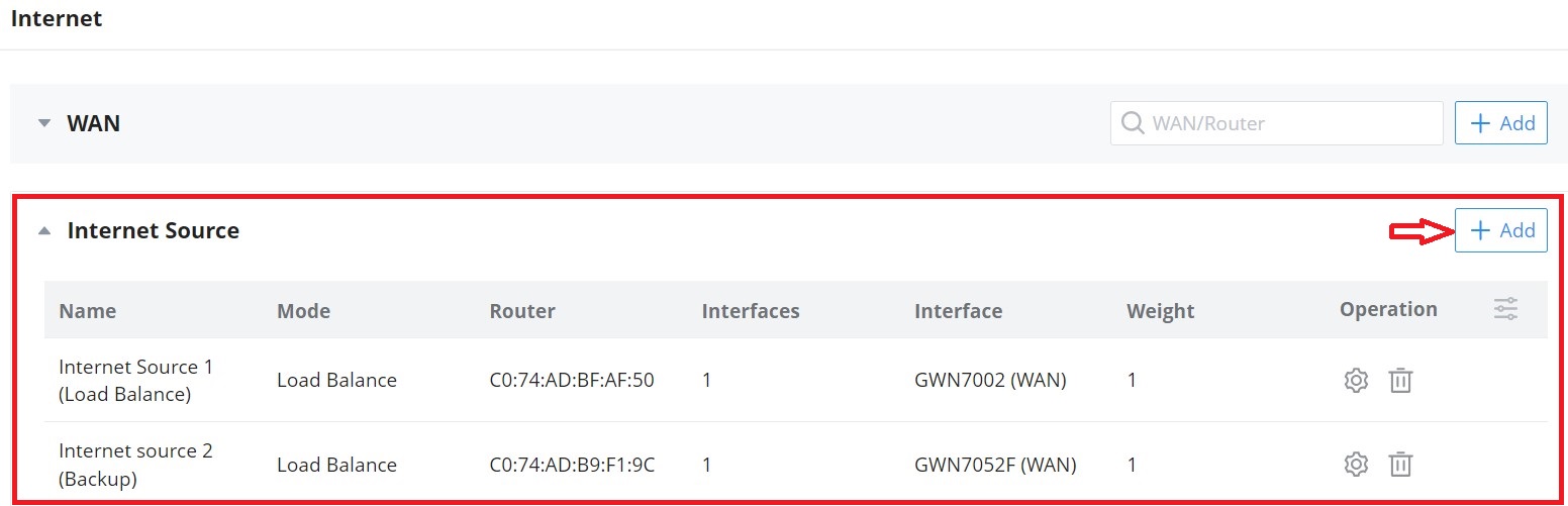
Here, the user can specify the name for the Load Balance or Backup, select the router/device group and specify the weight for each uplink.
- Default: If enabled, the subsequent WAN added by the router will be associated with the Internet Source
- Interface: In an Internet source, each interface can only be selected once, and only interfaces of the same router or the same device group are supported in an Internet source.
- Weight: Weight value determines the ratio at which connections are sent through each member. The default is 1. Enter a value from 1~10 with 10 being the highest weight.
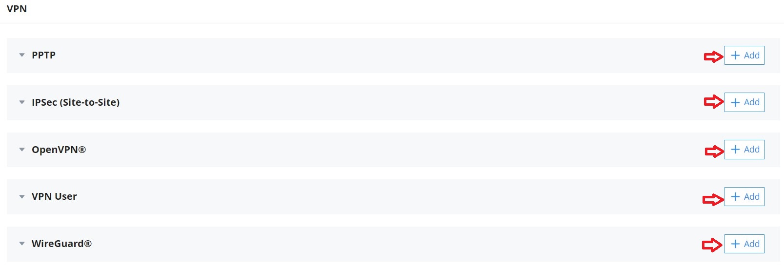
VPN
GWN.Cloud and GWN Manager support many VPNs including PPTP, IPSec (Site-to-Site), OpenVPN®, and WireGuard®.
GWN.Cloud and GWN Manager support more than one GWN router with single or multi-WAN on the same network, thus when configuring a VPN it’s important to specify which router (WAN/Device group) and interface will be used.
- PPTP: supports client and server.
- IPSec (Site-to-Site): supports manual and auto mode.
- OpenVPN®: supports client and server.
- WireGuard®: server side.
To add a new VPN or a VPN user, please navigate to Web UI → Settings → VPN and then click on the “Add” button as shown in the figure below:
PPTP
PPTP is a data-link layer protocol for wide area networks (WANs) based on the Point-to-Point Protocol (PPP) and developed by Microsoft that enables network traffic to be encapsulated and routed over an unsecured public network such as the Internet. Point-to-Point Tunneling Protocol (PPTP) allows the creation of virtual private networks (VPNs), which tunnel TCP/IP traffic through the Internet.
The below figure shows the configuration for adding a PPTP Client, it’s also possible the say way to add a PPTP Server. When adding a PPTP Client make sure to specify the username and password as well.
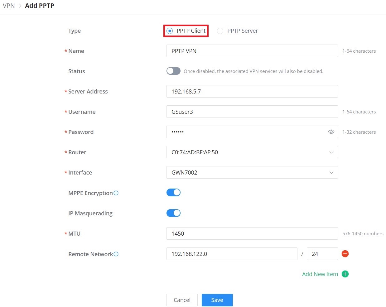
Type | Select either PPTP Client or PPTP Server to configure. |
Name | Enter a name for the PPTP client. |
Status | Toggle ON or OFF to enable or disable the PPTP Client VPN. Note: PPTP Server: Once disabled, the PPTP service will also be disabled. |
Server Address | Enter the IP/Domain of the remote PPTP Server. |
Username | Enter the Username for authentication with the VPN Server. |
Password | Enter the Password for authentication with the VPN Server. |
Router | Select from the drop-down list the router/device group that this VPN will be using. |
Interface | Select from the drop-down list the exact interface of the router/device group. |
MPPE Encryption | Enable / disable the MPPE for data encryption. By default, it’s disabled. |
IP Masquerading | This feature is a form of network address translation (NAT) which allows internal computers with no known address outside their network, to communicate to the outside. It allows one machine to act on behalf of other machines. |
Maximum Transmission Unit (MTU) | This indicates the size of the packets sent by the router. Please do not change this value unless necessary. |
Remote Subnet | Configures the remote subnet for the VPN. The format should be “IP/Mask” where IP could be either IPv4 or IPv6 and mask is a number between 1 and 32. example: 192.168.5.0/24 |
VPN – Add PPTP Client
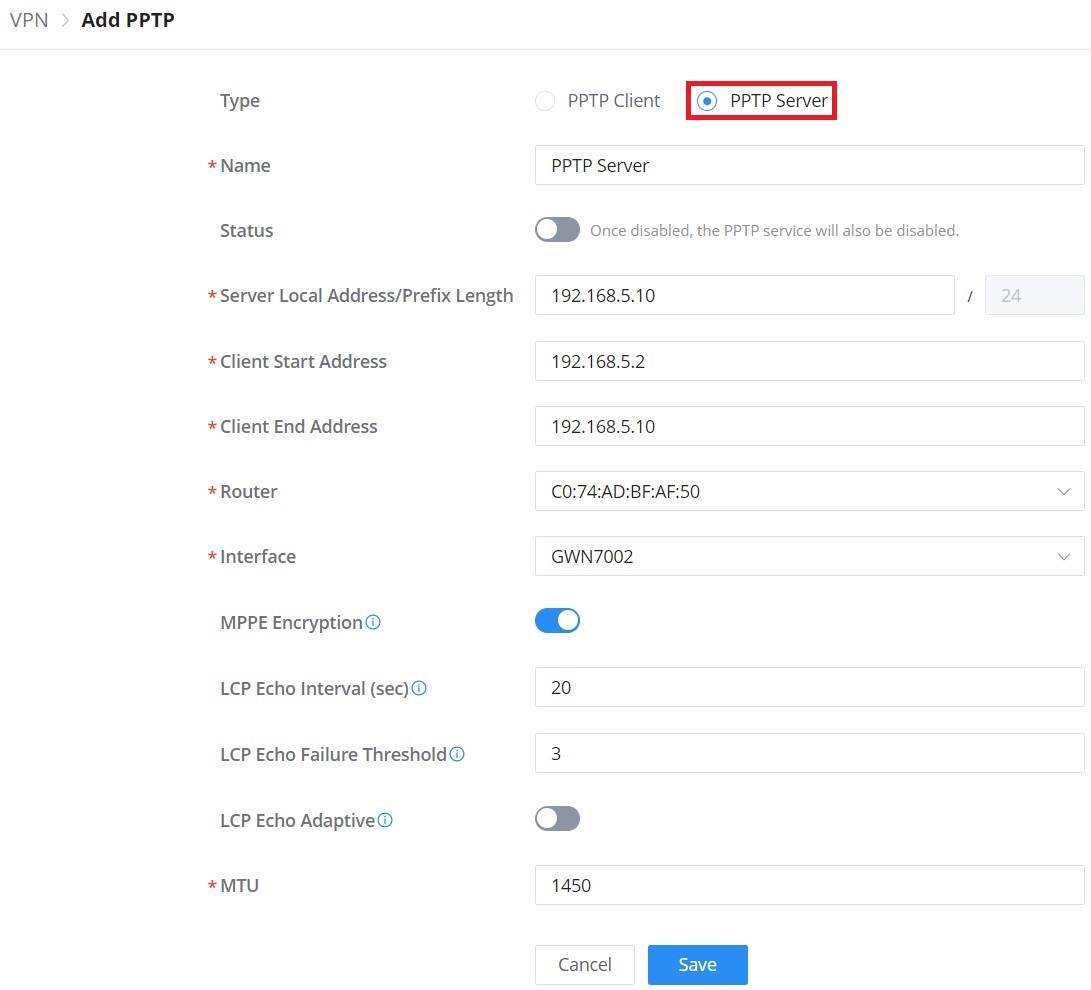
Type | Select either PPTP Client or PPTP Server to configure. |
Name | Enter a name for the PPTP Server. |
Status | Toggle ON or OFF to enable or disable the PPTP Client/Server VPN. Notes: Once disabled, the PPTP service will also be disabled. |
Server Local Address/Prefix Length | Specify the server local address with the prefix length |
Client Start Address | specify client start IP address |
Client End Address | specify client end IP address |
Router | Select from the drop-down list the router/device group that this VPN will be using. |
Interface | Select from the drop-down list the exact interface of the router/device group. |
MPPE Encryption | Enable / disable the MPPE for data encryption. By default, it’s disabled. |
LCP Echo Interval (sec) | Configures the LCP echo send interval. |
LCP Echo Failure Threshold | Set the maximum number of Echo transfers. If it is not answered within the set request frames, the PPTP server will consider that the peer is disconnected and the connection will be terminated. |
LCP Echo Adaptive |
|
Maximum Transmission Unit (MTU) | This indicates the size of the packets sent by the router. Please do not change this value unless necessary. By default is 1450. |
Maximum Receive Unit (MRU) | MRU indicates the size of the received packets. By default is 1450. |
Preferred DNS Server | specify the preferred DNS server. Ex: 8.8.8.8 |
Alternative DNS Server | specify the alternative DNS server. Ex: 1.1.1.1 |
VPN – Add PPTP Server
IPSec (Site-to-Site)
Internet Security protocol- IPsec is mainly used to authenticate and encrypt packets of data sent over the network layer. To accomplish this, they use two security protocols – ESP (Encapsulation Security Payload) and AH (Authentication Header), the former provides both authentications as well as encryption whereas the latter provides only authentication for the data packets. Since both authentication and encryption are equally desirable, most of the implementations use ESP.
IPsec supports two different encryption modes, they are Tunnel (default) and Transport mode. Tunnel mode is used to encrypt both payloads as well as the header of an IP packet, which is considered to be more secure. Transport mode is used to encrypt only the payload of an IP packet, which is generally used in gateway or host implementations.
GWN.Cloud and GWN Manager support IPsec (Site-to-Site) that can help encrypt and secure traffic between two sites using two GWN routers. It supports manual configuration and auto mode.
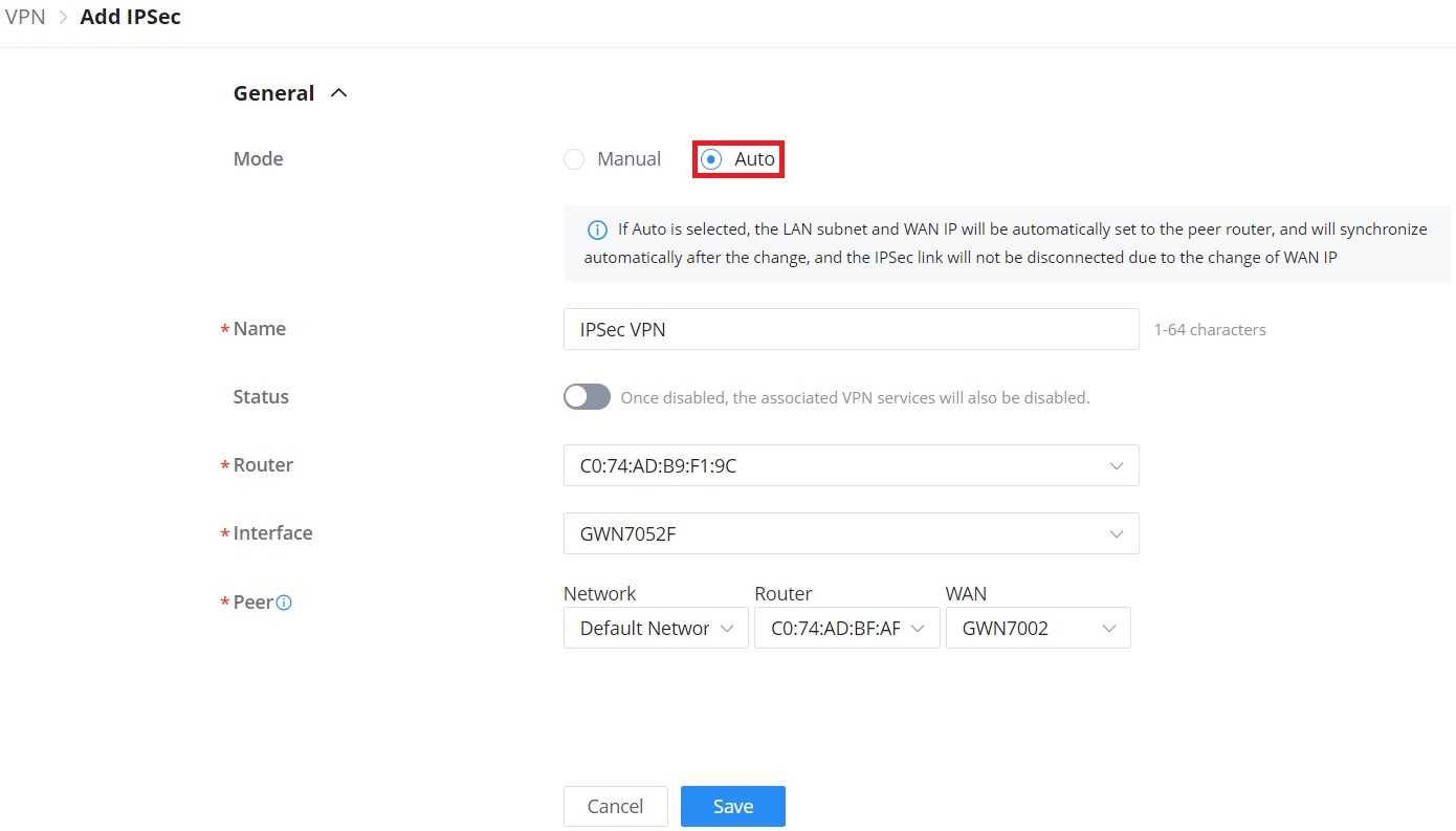
Mode | Select the mode: Manual or Auto. Note: If Auto is selected, the LAN subnet and WAN IP will be automatically set to the peer router, and will synchronize automatically after the change, and the IPSec link will not be disconnected due to the change of WAN IP. |
Name | Specify a name for IPSec VPN. |
Status | Toggle ON or OFF to enable or disable the IPSec VPN. Note: Once disabled, the associated VPN services will also be disabled. |
Router | Select from the drop-down list the router/device group that this VPN will be using. |
Interface | Select from the drop-down list the exact interface of the router/device group. |
Peer | Set the IP address of the WAN port so the peer network automatically connects with the current network. |
VPN – Add IPSec auto mode
For the manual mode, please refer to the figure and table below:
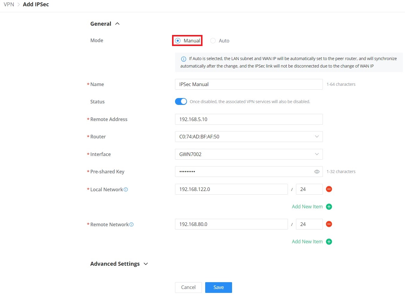
General | |
Mode | Select the mode: Manual or Auto. Note: If Auto is selected, the LAN subnet and WAN IP will be automatically set to the peer router, and will synchronize automatically after the change, and the IPSec link will not be disconnected due to the change of WAN IP. |
Name | Specify a name for IPSec VPN. |
Status | Toggle ON or OFF to enable or disable the IPSec VPN. Note: once disabled, the associated VPN services will also be disabled. |
Remote address | Specify the remote IP address |
Router | Select from the drop-down list the router/device group that this VPN will be using. |
Interface | Select from the drop-down list the exact interface of the router/device group. |
Pre-shared key | Specify a pre-shared key |
Local Network | Set the local IP address and mask length of the protected traffic. Please enter an IP address or subnet (e.g., 192.168.122.0/24) |
Remote Network | Set the peer IP address and mask length of the protected data flow. Please enter an IP address or subnet (e.g., 192.168.122.0/24) |
Advanced Settings | |
IKE Version | Select from the drop-down list the IKE version: IKEv1 or IKEv2. |
IKE SA Lifetime (sec) | Specify the IKE SA Lifetime (sec), default is 28800. |
Local Source IP | Enter the local Source IP address. |
Local ID | Set the local ID to identify the identity of the local device for the remote device to verify its legitimacy. |
Remote ID | Set the remote ID to authenticate the identity of the remote device. This parameter must be consistent with the local ID set on the remote device. |
Negotiation Mode | Select the negotiation mode from the drop-list, two options are list: Main or Aggressive. |
Encryption Algorithm | Select from the drop-down list the encryption algorithm to use, the available ones are:
Default is AES-256 |
Hash Algorithm | Select from the drop-down list the Hash algorithm to use, the available ones are:
Default is SHA2-256 |
DH Group | DH (Diffie-Hellman) group, select from the drop-down list the DH group, available groups are Group 2,5,14,19,20,21. |
Reconnect | Set whether to renegotiate the connection when it is about to expire. |
Number of Reconnections | Specify the number of reconnections. Note: The range is 0-10. 0 means continuous attempts to negotiate a connection. |
DPD (Dead Peer Detection) | Toggle ON or OFF DPD. Note: DPD is a method that is used by devices to check for the current existence and availability of IPsec peers. |
DPD Delay Time (sec) | Set the delay time for connecting DPD keepalive packets. |
DPD Idle Time (sec) | Set the amount of time to remain idle if no response is received from the peer. |
DPD Action |
|
IPSec SA Lifetime (sec) | Specify the IPSec SA lifetime, default is 3600. |
ESP Encryption Algorithm | Select from the drop-down list the ESP Encryption Algorithm, the available ones are:
Default is AES-256. |
ESP Hash Algorithm | Select from the drop-down list the ESP Hash Algorithm, the available ones are:
Default is SHA2-256 |
PFS Group | Select from the drop-down list the PFS group, the available ones are: Group 2,5,14. Default is disabled. |
VPN – Add IPSec Manual mode
OpenVPN®
OpenVPN® is a virtual private network system that secures site-to-site or point-to-point traffic in routed or bridged configurations and remote access facilities. It supports both the client and server side.
GWN.Cloud and GWN Manager support both OpenVPN® Client and Server side also certificates management for ease of use.
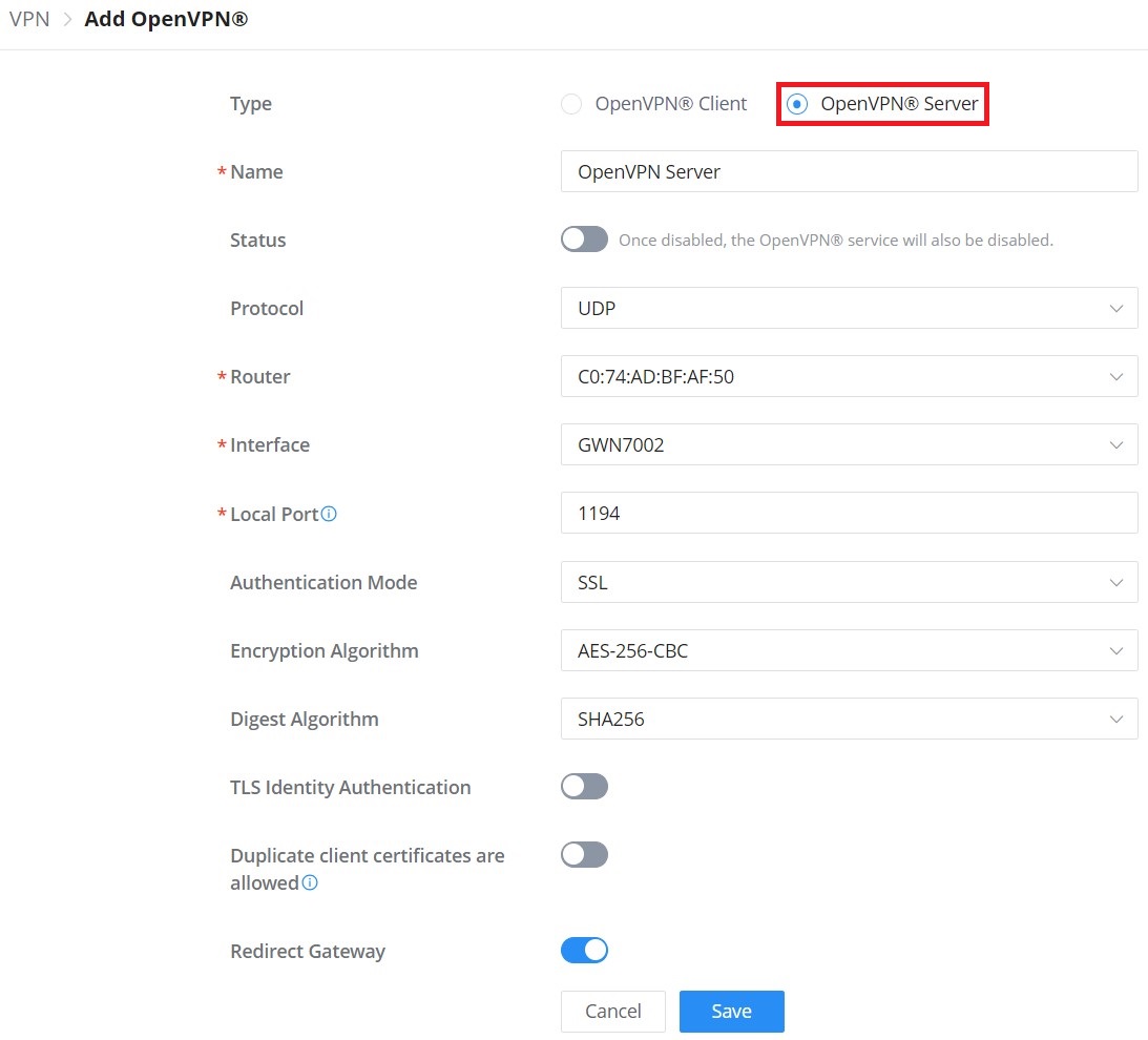
Type | Select the OpenVPN®: Client or Server |
Name | Enter a name for the OpenVPN® server. |
Status | Toggle ON or OFF to enable or disable the OpenVPN® Server. Note: Once disabled, the OpenVPN® service will also be disabled. |
Protocol | Choose the Transport protocol from the dropdown list, either TCP or UDP. The default protocol is UDP. |
Router | Select from the drop-down list the router/device group that this VPN will be using. |
Interface | Select from the drop-down list the exact interface of the router/device group. |
Local Port | Configure the listening port for OpenVPN® server. The default value is 1194. |
Authentication Mode | Choose the server mode the OpenVPN® server will operate with. 4 modes are available:
|
Encryption Algorithm | Choose the encryption algorithm from the dropdown list to encrypt data so that the receiver can decrypt it using same algorithm. |
Digest Algorithm | Choose digest algorithm from the dropdown list, which will uniquely identify the data to provide data integrity and ensure that the receiver has an unmodified data from the one sent by the original host. |
TLS Identicy Authentication | This option uses a static Pre-Shared Key (PSK) that must be generated in advance and shared among all peers. This feature adds extra protection to the TLS channel by requiring that incoming packets have a valid signature generated using the PSK key. |
TLS Identity Authentication Direction | Select from the drop-down list the direction of TLS Identity Authentication, three options are available (Server, Client or Both). |
TLS Pre-Shared Key | If TLS Identicy Authentication is enabled, enter the TLS Pre-Shared Key. |
Duplicate client certificates are allowed | Click on "ON" to allow duplicate Client Certificates |
Redirect Gateway | When redirect-gateway is used, OpenVPN® clients will route DNS queries through the VPN, and the VPN server will need to handle them. |
Push Routes | Specify route(s) to be pushed to all clients. Example: 10.0.0.1/8 |
LZO Compression Algorithm | Select whether to activate LZO compression or no, if set to “Adaptive”, the server will make the decision whether this option will be enabled or no. |
Allow Peer to Change IP | Allow remote change the IP and/or Port, often applicable to the situation when the remote IP address changes frequently. |
CA Certificate | Select a generated CA from the dropdown list or add one. |
Server Certificate | Select a generated Server Certificate from the dropdown list or add one. |
IPv4 Tunnel Network/Mask Length | Enter the network range that the GWN70xx will be serving from to the OpenVPN® client. Note: The network format should be the following 10.0.10.0/16. The mask should be at least 16 bits. |
VPN – Add OpenVPN® Server
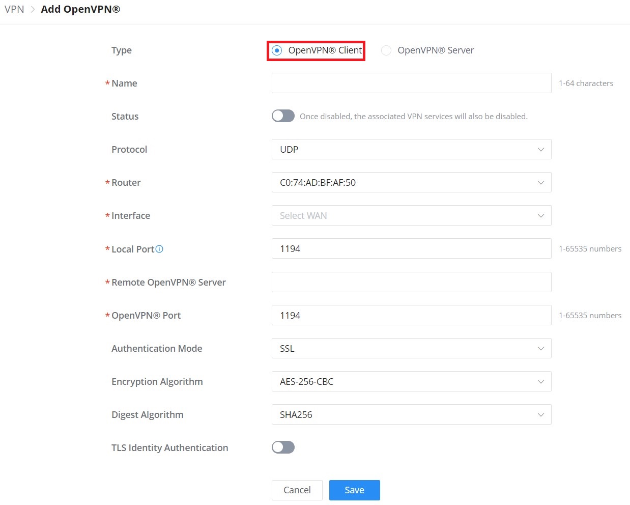
Type | Select the OpenVPN®: Client or Server |
Name | Enter a name for the OpenVPN® Client. |
Status | Toggle ON or OFF to enable or disable the OpenVPN® Client. Note: Once disabled, the associated VPN services will also be disabled. |
Protocol | Specify the transport protocol used.
Note: The default protocol is UDP. |
Router | Select from the drop-down list the router/device group that this VPN will be using. |
Interface | Select from the drop-down list the exact interface of the router/device group. |
Local Port | Configures the client port for OpenVPN®.The port between the OpenVPN® client and the client or between the client and the server should not be the same. |
Remote OpenVPN® Server | Configures the remote OpenVPN® server. Both IP address and domain name are supported. |
OpenVPN® Port | Configures the remote OpenVPN® server port |
Authentication Mode | Choose the server mode the OpenVPN® server will operate with. 4 modes are available:
|
Encryption Algorithm | Choose the encryption algorithm. The encryption algorithms supported are:
|
Digest Algorithm | Select the digest algorithm. The digest algorithms supported are:
|
TLS Identity Authentication | Enable TLS identity authentication direction. |
TLS Identity Authentication Direction | Select the indentity authentication direction.
|
TLS Pre-Shared Key | Enter the TLS pre-shared key. |
Routes | Configures IP address and subnet mask of routes, e.g., 10.10.1.0/24. |
Deny Server Push Routes | If enabled, client will ignore routes pushed by the server. |
IP Masquerading | This feature is a form of network address translation (NAT) which allows internal computers with no known address outside their network, to communicate to the outside. It allows one machine to act on behalf of other machines. |
LZO Compression | Select whether to activate LZO compression or no, if set to “Adaptive”, the server will make the decision whether this option will be enabled or no. |
Allow Peer to Change IP | Allow remote change the IP and/or Port, often applicable to the situation when the remote IP address changes frequently. |
CA Certificates | Click on “Upload” and select the CA certificate |
Client Certificate | Click on “Upload” and select the Client Certificate. |
VPN – Add OpenVPN® Client
VPN User
In this section, the user can add a VPN user for either PPTP VPN or OpenVPN®. Please refer to the figure and table below:
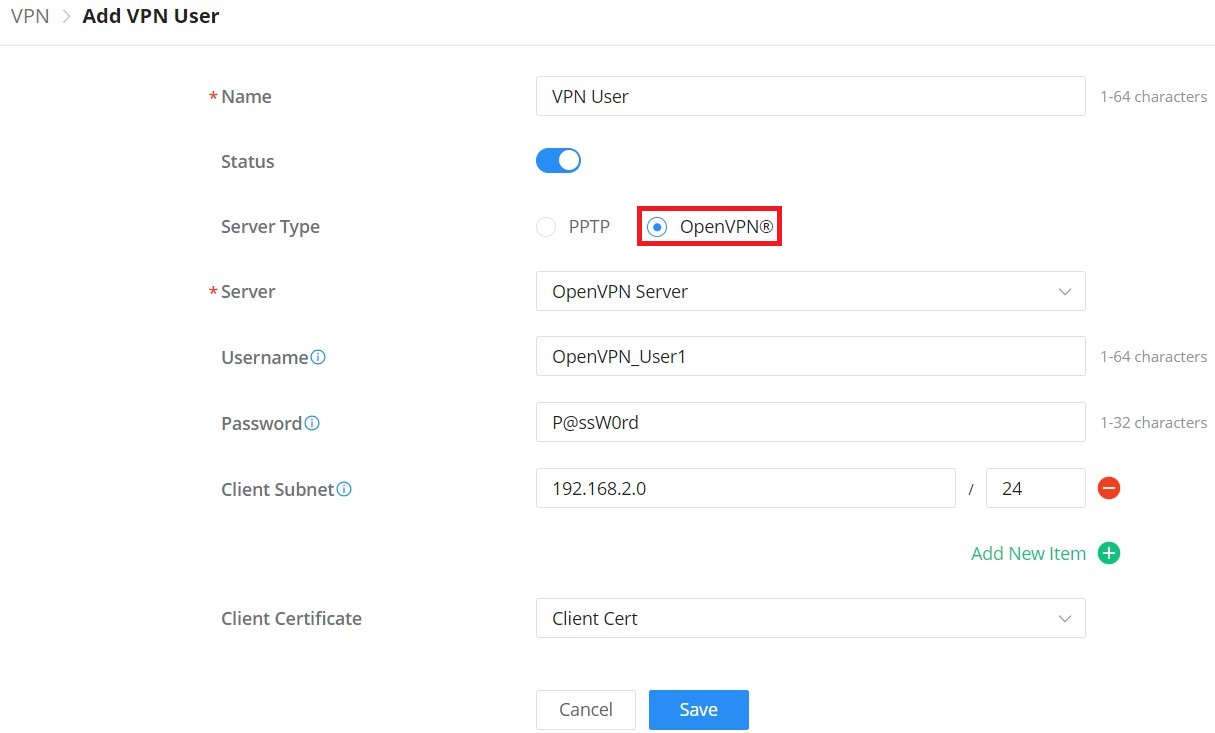
Name | Enter a name for the user. This name will not be used to log in. |
Status | Enable or disable this account. |
Server Type | Choose the type of the server.
|
Server Name | Select the VPN server fromt the drop-list |
Username | Enter the username. This username will be used to log in. Note: only alphanumeric characters and @ ! $ % - _ are supported. |
Password | Enter the password. Note: only alphanumeric characters and @ ! $ % - _ are supported. |
Client Subnet | Set the IP address and mask length of the subnet for the client to access. Please enter an IP address or subnet (e.g., 192.168.2.0/24) |
Only if OpenVPN® is selected | |
Client Certificate | Select from the drop-down list the client certificate. |
VPN – Add VPN User
WireGuard®
WireGuard® is a free and open-source VPN solution that encrypts virtual private networks, easy to use, high performance and secure.
GWN.Cloud and GWN Manager support WireGuard® as well, a Server local address can be specified while a private key can be generated with one click then after that the public key can be copied and shared with the client.
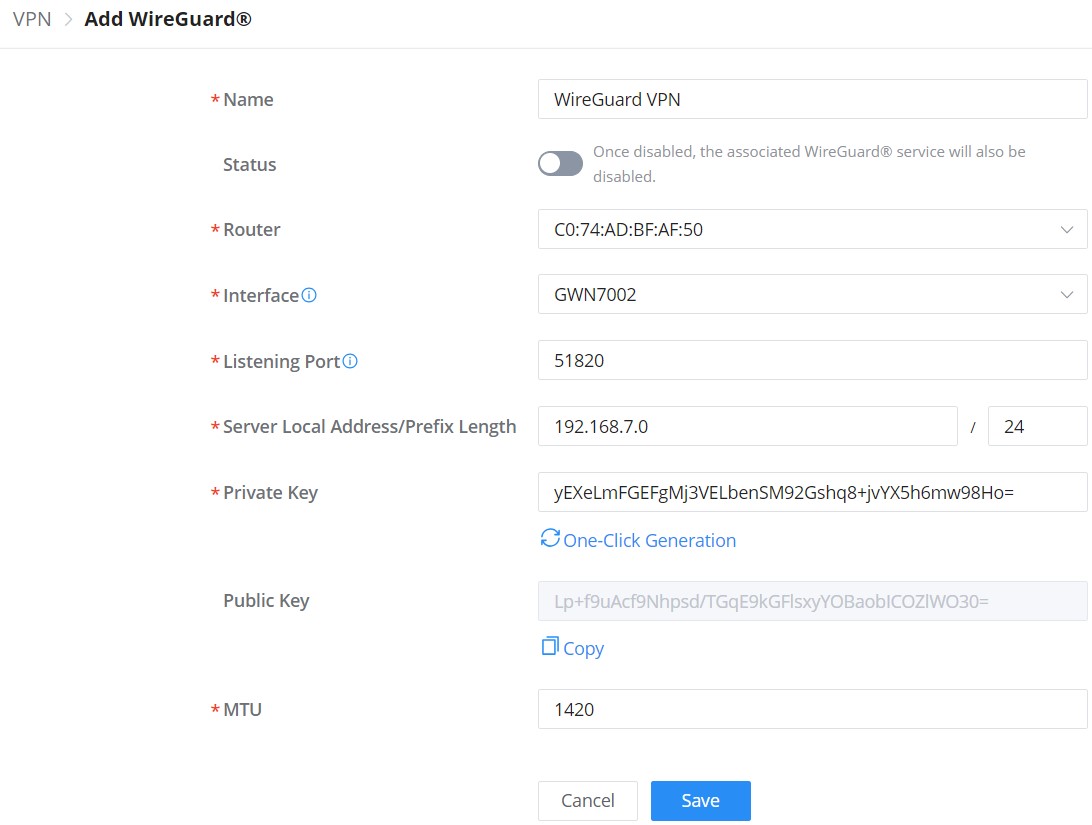
Name | Specify a name for Wireguard® VPN. |
Status | Toggle ON or OFF to enable or disable the Wireguard® VPN. |
Router | Select from the drop-down list the router/device group that this VPN will be using. |
Interface | Select from the drop-down list the exact interface of the router/device group. Note: one WAN only supports creating one WireGuard®. |
Listening Port | Set the local listening port when establishing a WireGaurd® tunnel. Default: 51820 |
Server Local Address/Prefix Length | Specify the server local address with the prefix length |
Private Key | Click on "One-Click Generation" text to generate a private key. |
Public Key | The public key will be generated according to the private key. Click on "Copy" text to copy the public key. |
MTU | This indicates the size of the packets sent by the router. Please do not change this value unless necessary. By default is 1450. |
VPN – Add WireGuard®
Traffic Management
On this page, the user can manage traffic by either adding static routes (IPv4 or IPv6) or adding Policy Routes.
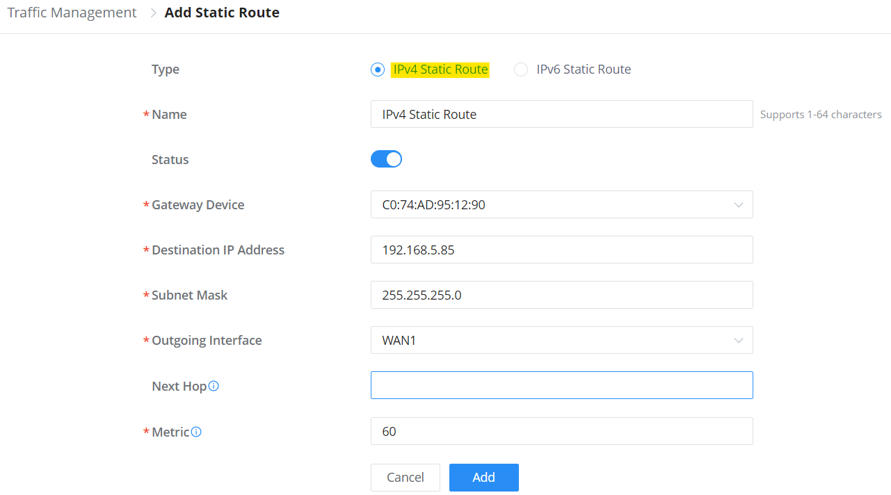
Static Routes
Static routing is a form of routing by manually configuring the routing entries, rather than using a dynamic routing traffic for any service that requires a static address that never changes.
GWN.Cloud and GWN Manager support setting manually IPv4 or IPv6 Static Routes which can be accessed from Web UI → Settings → Traffic Management page → Static Routes section.
All the Static routes either IPv4 or IPv6 will be listed here.
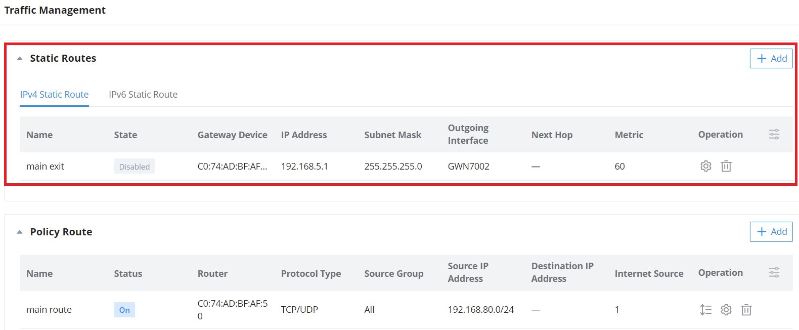
Click on ![]() button to add a static route, the user has the option between IPv4 or IPv6.
button to add a static route, the user has the option between IPv4 or IPv6.
Policy Route
GWN.Cloud and GWN Manager support managing more than one GWN router on the same network, with multiple GWN routers added, the user will have many internet sources, which will enable the user to specify which traffic can be forwarded to an internet source (Load Balance/Backup). Also, a schedule can be applied to this policy route to only be active based on the schedule selected.
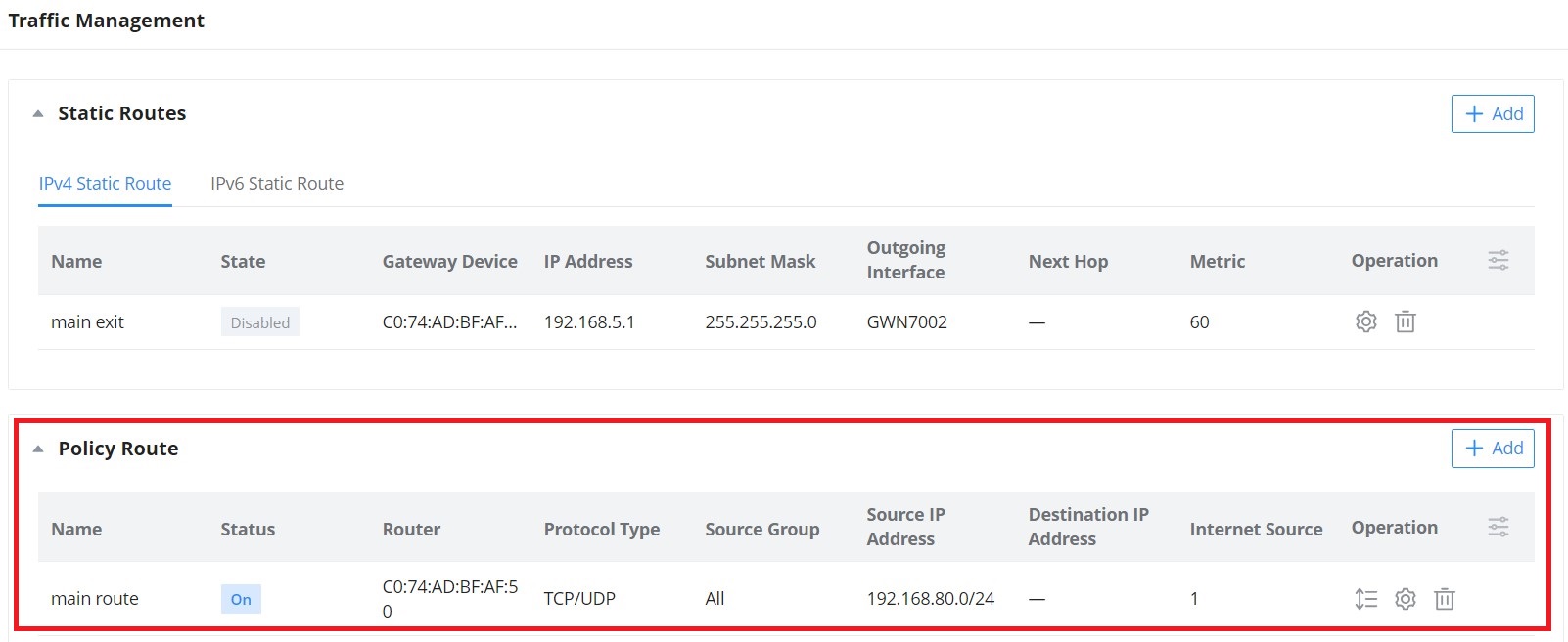
Navigate Web UI → Settings → Traffic Management page → Policy route section and then click on the “Add” button to add a policy route, please refer to the figure below:
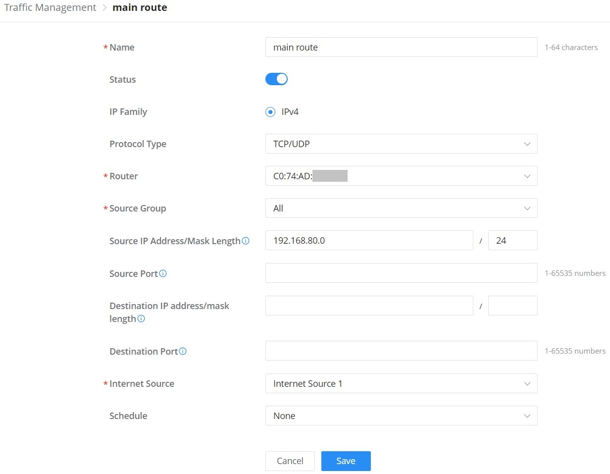
Name | Specify a name for the policy route |
Status | Toggle ON or OFF to enable or disable the policy route |
IP Family | IP Family, default is IPv4 |
Protocol Type | Select from the drop-down list the protocol type:
|
Router | Select from the drop-down list the router or the device group Note: for device groups, only router group is supported |
Source Group | Select the source group from the drop-down list |
Source IP Address/Mask Length | Set the source IP address and mask length of the packet to be matched. Please enter an IP address or subnet (e.g., 192.168.122.0/24) |
Destination IP address/mask length | Set the destination IP address and mask length to match the packet. For example, 192.168.122.0/24 |
Internet Source | Select the internet source (WAN/Load Balance/Backup) from the drop-down list |
Schedule | Select a schedule from the drop-down list or click on "Add New Schedule" to add one. |
Add Policy Route
Firewall and Security
The Firewall & Security page combines all the configurations related to firewall and security, split into 5 sections (Port Forwarding, Wired Firewall Rules, Wireless Firewall Rules, Rogue AP, and Advanced Security Settings.
Click on a section to expand the list or click on ![]() button to add more.
button to add more.
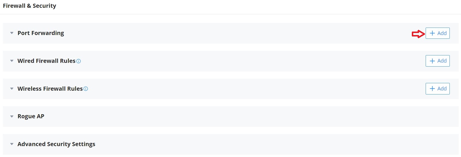
Port Forwarding
Port forwarding is redirecting the communication request from one address and port to another address and port. A source IP Address and port will be mapped to a Destination IP Address, port, and Group.
To add port forwarding, navigate to Web UI → Settings → Firewall & Security page → Port Forwarding tab.
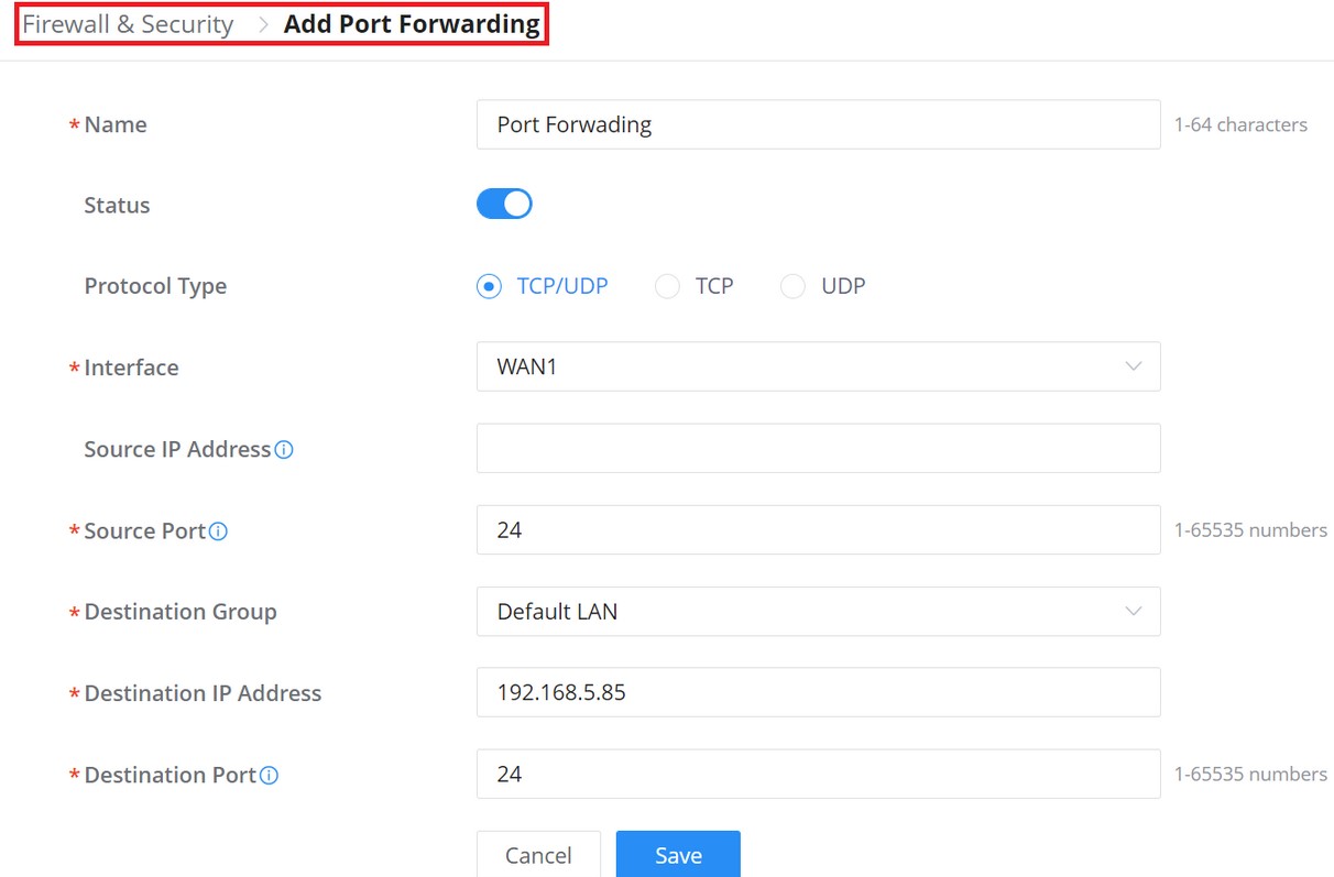
Refer to the following table for the port-forwarding option when editing or creating a port-forwarding rule:
Name | Enter a name for the port forwarding rule. |
Status | Toggle on/off the rule status. |
Protocol Type | Select a protocol, users can select TCP, UDP or TCP/UDP. |
Interface | Select the WAN port |
Source IP Address | Sets the IP address that external users access to this device. If not set, any IP address on the corresponding WAN port can be used |
Source Port | Set a single or a range of Ports. |
Destination Group | Select VLAN group. |
Destination IP Address | Set the destination IP address. |
Destination Port | Set a single or a range of Ports. |
Port Forwarding
Wired Firewall Rules
The administrator can Accept, Reject, or Drop wired traffic using inbound rules or forwarding rules, navigate to Web UI → Settings → Firewall & Security page → Wired Firewall Rules tab.
- Accept: To allow the traffic to go through.
- Deny: A reply will be sent to the remote side stating that the packet is rejected.
- Drop: The packet will be dropped without any notice to the remote side.
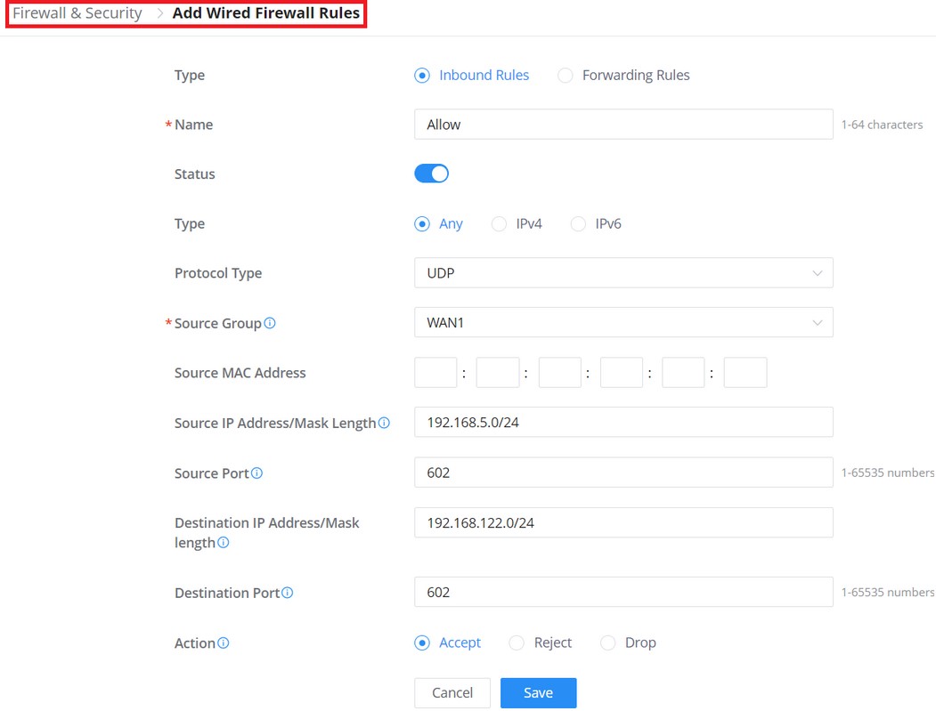
Type | Select the type of the firewall rule: Inbound or Forwarding rule |
Name | Enter a name for the wired firewall rule. |
Status | Toggle on or off the wired firewall rule. |
IP Family | Select the IP Family used: IPv4, IPv6 or Any |
Protocol Type | Select the protocol type from the drop-down list. |
Source Group | Select the source group, it can be either a WAN or VLAN. Note: If set to "All", more specific rules will take priority. |
Source MAC Address | Specify a source MAC Address, else the rule will be applied on all MAC addresses. |
Source IP Address/Mask Length | Sets the source IP address of the external device. Please enter an IP address or subnet (e.g., 192.168.122.0/24) |
Source Port | Separate multiple ports and port ranges with commas (e.g., "4, 5-10"). |
Destination Group | Select the Destination group: WAN or VLAN Note: This option is only available when selecting Forwarding rules |
Destination IP Address/Mask length | Sets the IP address that external devices access the router. Please an IP address or subnet (e.g., 192.168.122.0/24). |
Destination Port | Separate multiple ports and port ranges with commas (e.g., "4, 5-10"). |
Action |
|
Wired Firewall Rules
Wireless Firewall Rules
This section is located under Web UI → Settings → Firewall & Security page → Wireless Firewall rules tab, it does allow users to control the outgoing and incoming traffic from clients connected to the adopted/paired GWN devices by manually setting up policies to either deny or permit the traffic for wireless traffic based on protocol type and by specifying SSIDs and destinations.
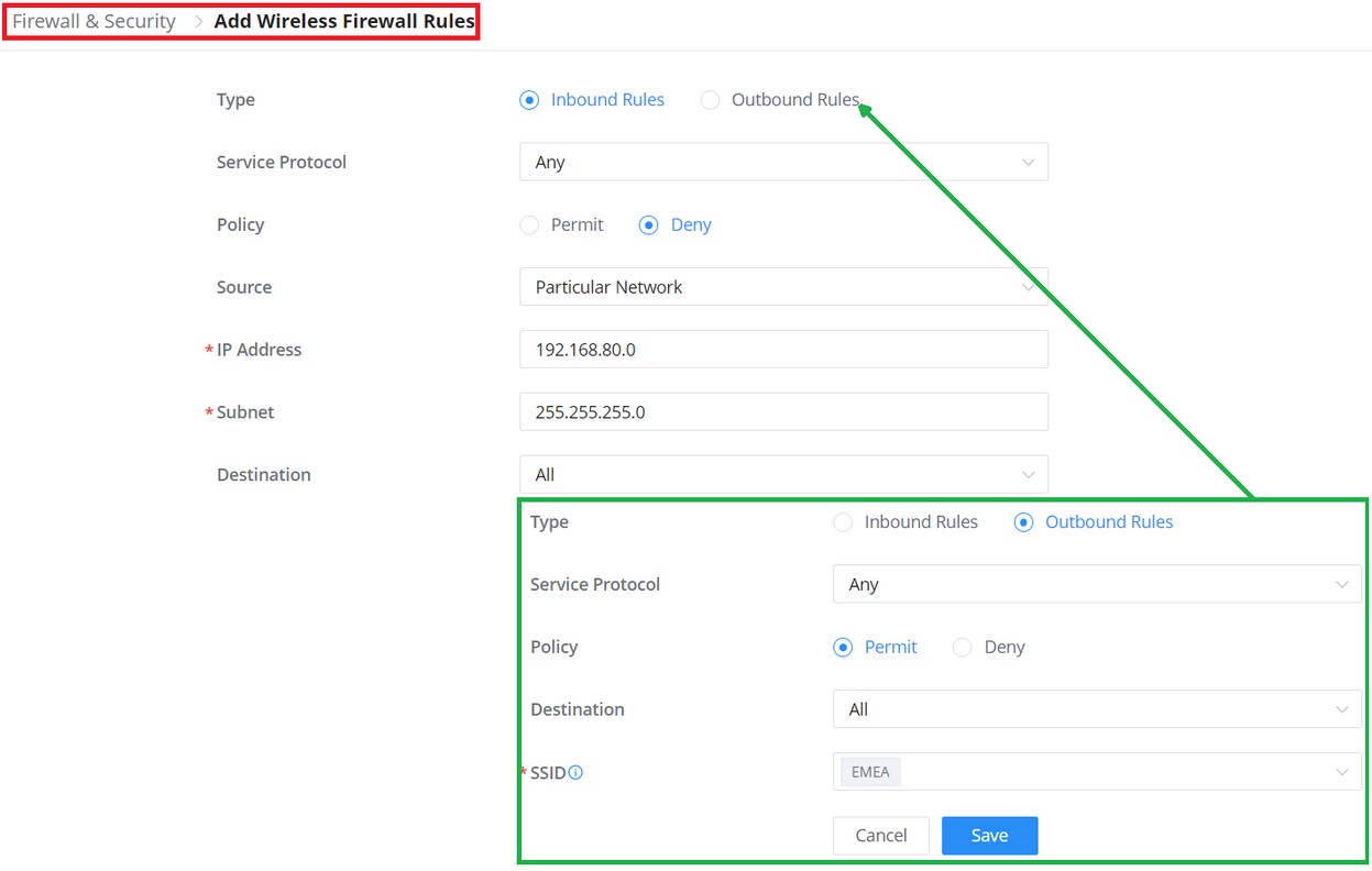
Type | Select the type of the firewall rule: Inbound rules or Outbound rules |
Name | Enter a name for the wireless firewall rule. |
Service Protocol | Select the Service protocol type from the drop-down list. |
Policy |
|
Source | Select the source, it can be from a Particualar IP or Network then enter the IP and/or the subnet. Note: this option is only available when the type selected is Inbound rules. |
Destination | Select the destination, it can be from a Particualar IP, Network or Domain. then enter the IP/Domain and/or the subnet. |
SSID | If All is selected, this rule will also be applied to new SSIDs (Wireless LAN). Note: this option is only available when the type selected is Outbound rulesl |
Add Wireless Firewall Rules
Rogue AP
GWN Cloud and GWN Manager offer the ability to prevent malicious intrusion into the network and increase the wireless security access of clients when introducing the Rogue AP detection feature to the adopted/paired GWN devices. The detected devices will be listed with all the details under the “Alerts” page for further intervention.
Navigate to Settings → Firewall & Security page → Rogue AP section, The below figure shows the configuration page to enable Rogue AP detection.
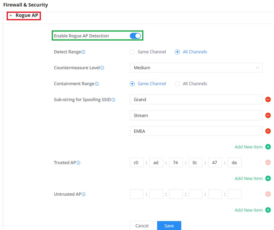
Enable Rogue AP Detection | Select to either to enable or disable Rogue AP scan. |
Detect Range | Specify the rogue AP detect range.
Default is Same Channel. |
Countermeasure Level | Countermeasures level specifies the type of attacks which will be
Default is Disabled. |
Containment Range | Specify the containment range:
Default is Same Channel. |
Sub-string for Spoofing SSID | The AP broadcasting SSID with the specified string will be classified as a Spoofing SSID. |
Trusted AP | You can specify MAC address of the trusted AP, which should be |
Untrusted AP | You can specify MAC address of the untrusted AP, which should be formatted as XX:XX:XX:XX:XX:XX. If an AP is defined as untrusted AP, countermeasures will be executed on it when countermeasure is enabled. |
Rogue AP
Application Layer Gateway (ALG)
ALG stands for Application Layer Gateway. Its purpose is to prevent some of the problems caused by router firewalls by inspecting VoIP traffic (packets) and if necessary modifying it.
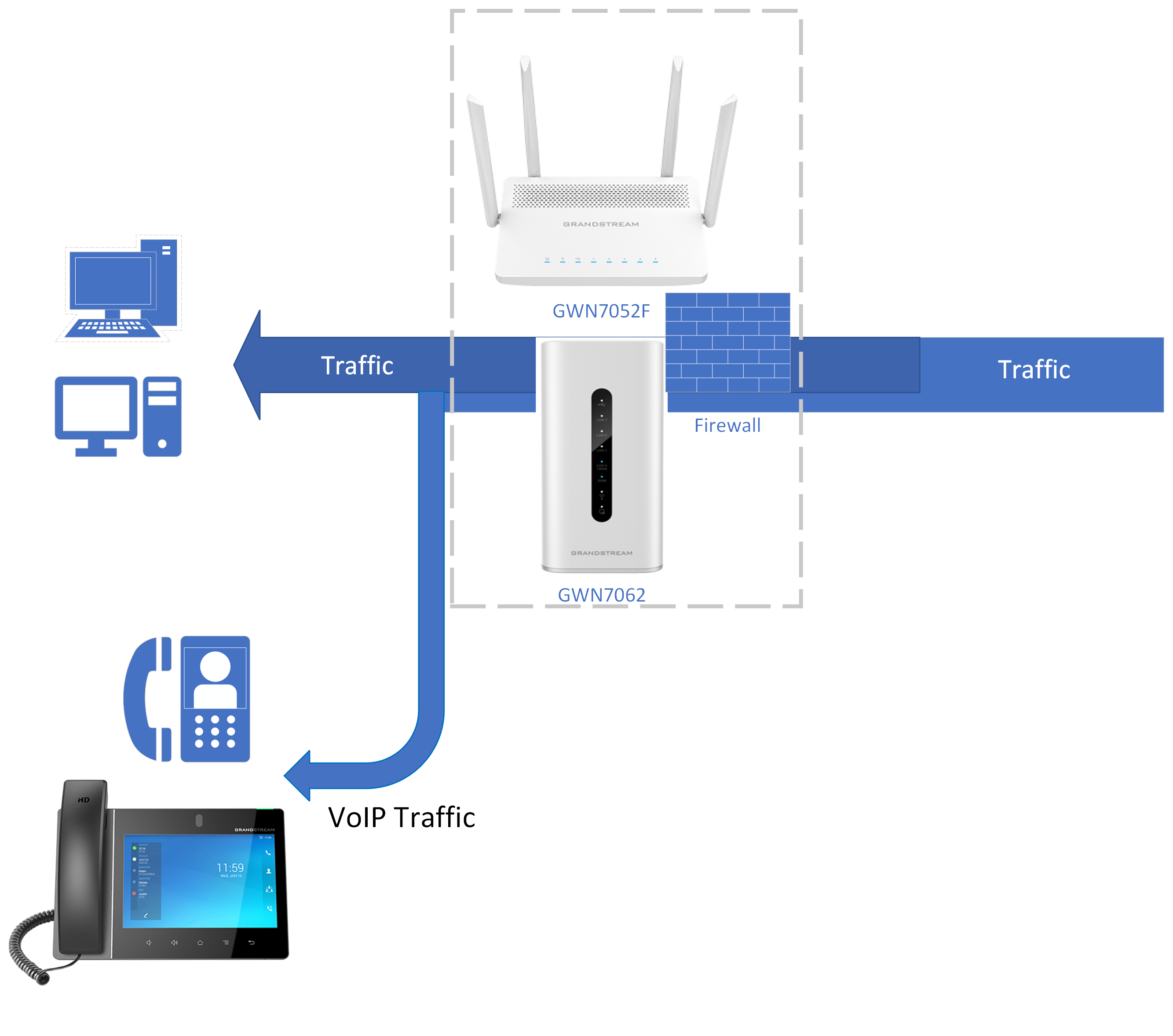
To configure ALG, navigate to Web GUI → Settings → Firewall & Security page → Advanced Security Settings tab.
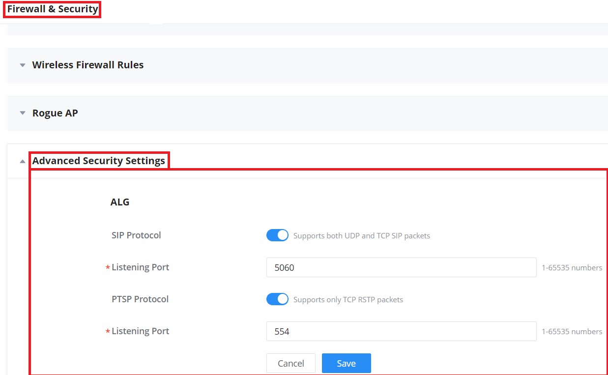
PROFILES
Portal policy
The policy configuration page allows adding multiple captive portal policies which will be applied to SSIDs and contains options for different authentication types a splash page that can be easily configured as shown in the next section.
Each SSID can be assigned a different captive portal policy, for example, company ABC could have a specified Wi-Fi for staff people who can access via a portal policy requiring a user username and password for authentication and another SSID for guest people who can sign in via their Facebook account; also, they could assign either an internal or external Splash page.
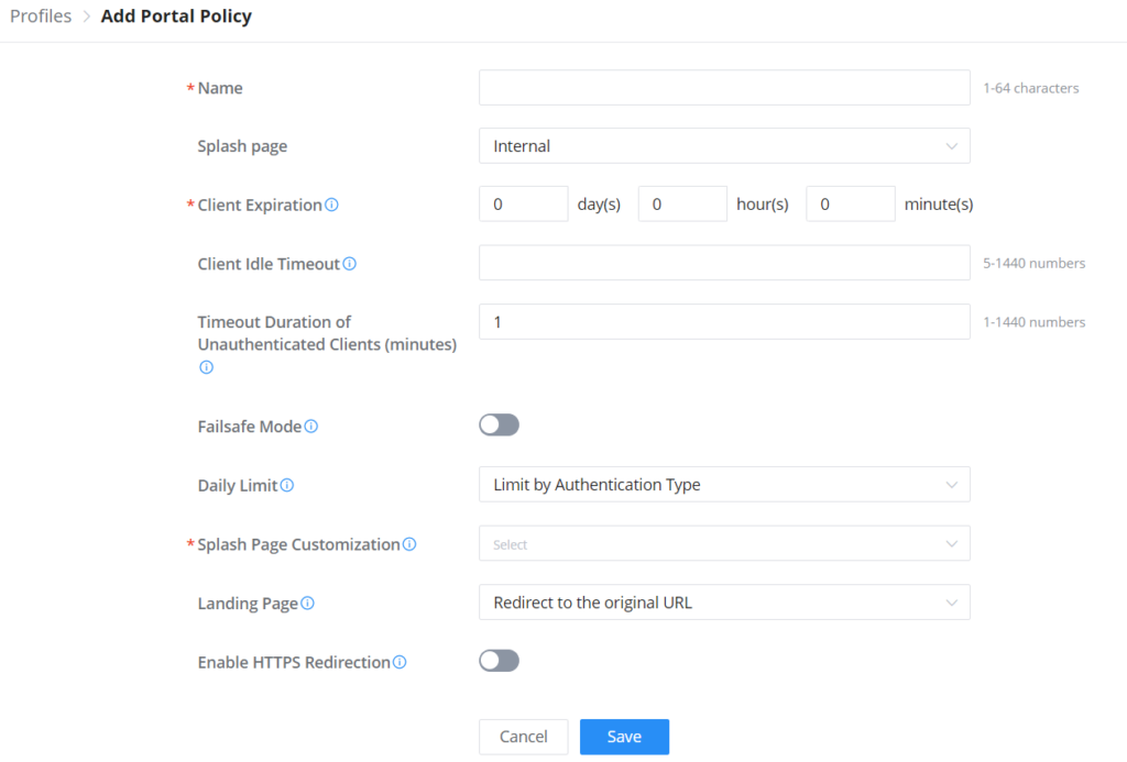
Internal Splash Page
Please refer to the table below when configuring the Internal Splash Page.
Name | Enter the name of the Captive Portal policy |
Splash Page | Select Splash Page type, Internal or External. Note: this table is only about internal splash page. |
Client Expiration | Configures the period of validity, after the valid period, the client will be re-authenticated again. |
Client Idle Timeout | Specify the idle timeout value for guest network connection. Once timed out, guest should re-authenticate for further network use. Note: this option is not applicable to voucher guests and payment guests. |
Timeout Duration of Unauthenticated Clients (minutes) | Set the timeout time for unauthenticated clients. After the timeout, unauthenticated client devices are disabled from using Wi-Fi. |
Failsafe Mode | Once enabled, guest can access internet when the authentication server or external portal is unreachable. Note: only the Radius, custom field and Voucher authentications support this feature. |
Daily Limit |
|
Splash Page Customization | Select a splash page from the drop-down list or click "Add New Splash Page". |
Landing Page | Choose the landing page, 2 options are available:
|
Enable HTTPS Redirection | Check to enable/disable HTTPS service. If enabled, both HTTP and HTTPS requests sent from stations will be redirected by using HTTPS protocol. And station may receive an invalid certification error while doing HTTPS browsing before authentication. If disabled, only the HTTP request will be redirected. |
Enable Secure Portal | If enabled, HTTPS protocol will be used in the communication between STA and AP. Otherwise, the HTTP protocol will be used. |
Pre Authentication Rule(s) | |
Destination | Destination can be either IP Address, Hostname or Subnet/Prefix |
Service |
|
Post Authentication Rule Type |
|
Post Authentication Rule(s) | |
Destination | Destination can be either IP Address, Hostname or Subnet/Prefix |
Service |
|
Portal Policy – Internal Splash Page
External Splash page
Please refer to the table below when configuring the External Splash Page.
Name | Enter the name of the Captive Portal policy |
Splash Page | Select Splash Page type, Internal or External. Note: this table is only about external splash page. |
Platform | Select the Radius Authentication Method provided by external portal platform. |
If Linkyfi, Purple or Universal Platform is selected | |
External Splash Server Address | Enter the External Splash Page URL, and make sure to enter the pre-authentication rules request by the external portal platform in the pre-authentication configuration option. |
RADIUS Authentication | Select a RADIUS from the drop-down list or click on "Add New Radius". |
If Aiwifi platform is selected | |
URL Pre-shared Key | The configuration will be used to generate the signature. Please enter 20-32 characters, support entering numbers, English, characters (excluding spaces) |
Timeout Duration of Unauthenticated Clients (minutes) | Set the timeout time for unauthenticated clients. After the timeout, unauthenticated client devices are disabled from using Wi-Fi. |
External page | Please enter the Redirect URL provided by external portal platform. |
Enable HTTPS Redirection | Check to enable/disable HTTPS service. If enabled, both HTTP and HTTPS requests sent from stations will be redirected by using HTTPS protocol. And station may receive an invalid certification error while doing HTTPS browsing before authentication. If disabled, only the HTTP request will be redirected. |
Pre Authentication Rule(s) | |
Destination | Destination can be either IP Address, Hostname or Subnet/Prefix |
Service |
|
Post Authentication Rule Type |
|
Post Authentication Rule(s) | |
Destination | Destination can be either IP Address, Hostname or Subnet/Prefix |
Service |
|
Portal Policy – External Splash Page
Splash page
Splash page allows users with an easy-to-configure menu to generate a customized splash page that will be displayed to the users when trying to connect to the Wi-Fi.
On this menu, users can create multiple splash pages and assign each one of them to a separate captive portal policy to enforce the selected authentication type.
The generation tool provides an intuitive “WYSIWYG” method to customize a captive portal with a very rich manipulation tool.
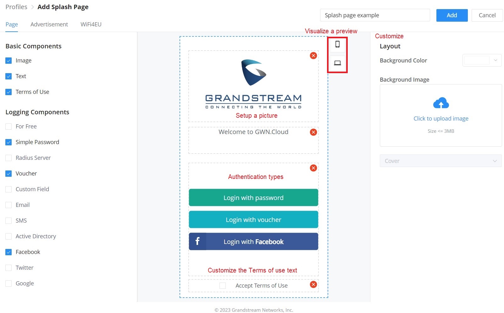
Users can set the following:
- Authentication type: Add one or more ways from the supported authentication methods:
For Free | Clients can log in without authentication. |
Simple Password | The user can specify a password that clients must enter to authenticate. |
Radius Server | Authentication using a RADIUS server. |
Voucher | Authentication using a Voucher code. |
Custom Field | The user can specify a custom field depending on the information needed:
|
Authentication using Email. | |
SMS | Authentication using SMS, with Twilio or Amazon SMS Service Provider. |
Active Directory | Authentication using Active Directory. |
Authentication using Facebook account. | |
Authentication using Twitter account. | |
Authentication using Google account. |
Splash page – Authentication types
- Set up a picture (Company Logo) to be displayed on the splash page.
- Customize the layout of the page and background colors.
- Customize the Terms of Use text.
- Visualize a preview for both mobile devices and laptops.
Advertisement
On this page, advertisements can be enabled and forced on each access point, where users will be forced to view media content (images or videos) before being granted access to the network.
Click on the “Add” button to add media content (images or videos) then specify the “Force to watch duration” (in seconds).
Rotation: when there are many media contents, the user can specify the rotation (Random, Regular interval, or Regular time), then the preset time can be specified.
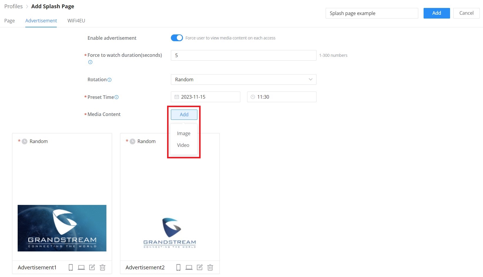
WiFi4EU
Once enabled, the top area of the splash page will display the information about WiFi4EU. The language can be set as well as the Network UUID.
Self-test modus: A WiFi4EU supplier can test if the snippet is correctly installed and if its portal is compliant by enabling the snippet self-test modus.
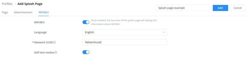
Port Profile
Port profiles are a convenient way to provision a GWN device (ex: GWN switches) interfaces easily. Name a profile then select the relevant configurations, like VLAN, Rate, Speed limit, LLDP, etc. Also for security, we can enable Storm control, Port Isolation, Port Security, and 801.1X Authentication.
To create a new Port Profile or edit an existing one, please navigate to Web UI → Settings → Profiles page → Port Profile section.
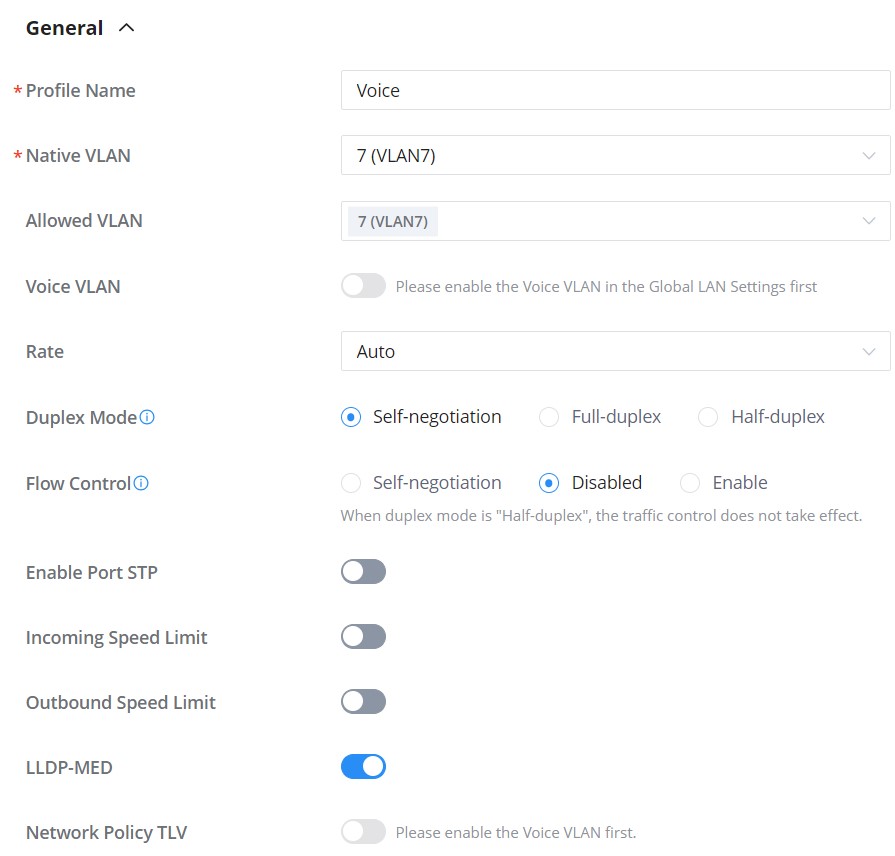
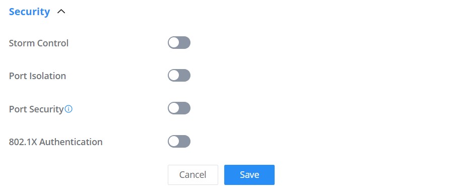
General | |
Profile Name | Specify a name for the profile. |
Native VLAN | Select from the drop-down list the native VLAN (Default LAN). |
Allowed VLAN | Check the allowed VLANs from the drop-down list (one VLAN or more). |
Voice VLAN | Toggle ON or OFF Voice VLAN. Note: Please first enable the Voice VLAN in the Global LAN Settings. |
Rate | Specify the rate (port speed) from the drop-down list. |
Duplex Mode | Select the duplex mode:
|
Flow Control | When enabled, if congestion occurs on the local device, the device sends a message to the peer device to notify it to stop sending packets temporarily. After receiving the message, the peer device stops sending packets to the local device. Note: When duplex mode is "Half-duplex", the traffic control does not take effect. |
Enable Port STP | Toggle ON or OFF the Port STP. |
Incoming Speed Limit | Toggle ON or OFF the incoming speed limit. |
CIR (Kbps) | Configures the Committed Information Rate, which is the average rate of the traffic to pass through. |
Outbound Speed Limit | Toggle ON or OFF the outbound speed limit. |
CIR (Kbps) | Configures the Committed Information Rate, which is the average rate of the traffic to pass through. |
LLDP-MED | Toggle ON or OFF the LLDP-MED. |
Network Policy TLV | Toggle ON or OFF the network policy TLV. |
Security | |
Storm Control | Toggle ON or OFF storm control. |
Broadcast | Toggle ON or OFF Broadcast and then specify the control trhreshold (pps = packet per second). |
Unknown Multicast | Toggle ON or OFF Broadcast and then specify the control trhreshold (pps = packet per second). |
Unknown Unicast | Toggle ON or OFF Unknown Unicast and then specify the control trhreshold (pps = packet per second). |
Port Isolation | Toggle ON or OFF port isolation. |
Port Security | Toggle ON or OFF port security. Note: after enabled, start MAC address learning including the dynamic and static MAC addresses. |
Maximum number of MACs | Specify the maximum number of MAC addresses allowed. Note: after the maximum number is reached, if a packet with a non-existing source MAC address is received, regardless of whether the destination MAC address exists or not, the switch will consider that there is an attack from an illegal user, and will protect the interface according to the port protection configuration. |
Sticky MAC | Toggle ON or OFF Sticky MAC. Note: after enabled, the interface will convert the learned secure dynamic MAC address into Sticky MAC. If the maximum number of MAC addresses has been reached, the MAC addresses in the non-sticky MAC entries learned by the interface will be discarded, and whether to report a Trap alert is determined according to the port protection configuration. |
802.1X Authentication | Toggle ON or OFF 802.1x authentication. |
User Authentication Mode | Select the user authentication mode from the drop-down list
|
Method | Select the method from the drop-down list. |
Guest VLAN | Toggle Guest VLAN ON or OFF. Note: Enable the Guest VLAN in the Global LAN Settings first. |
Port Control | Select the port control from the drop-down list:
|
Re-authentication | Configures whether to enable re-authentication for the device connected to the port. |
Add port profile
Once the Port profile is added the user can apply it on a GWN device/device group ports (ex: GWN switches).
Under the Devices page, select the relevant device, and under the Port tab, select the ports then apply the Port Profile on these ports. please refer to the figure below:
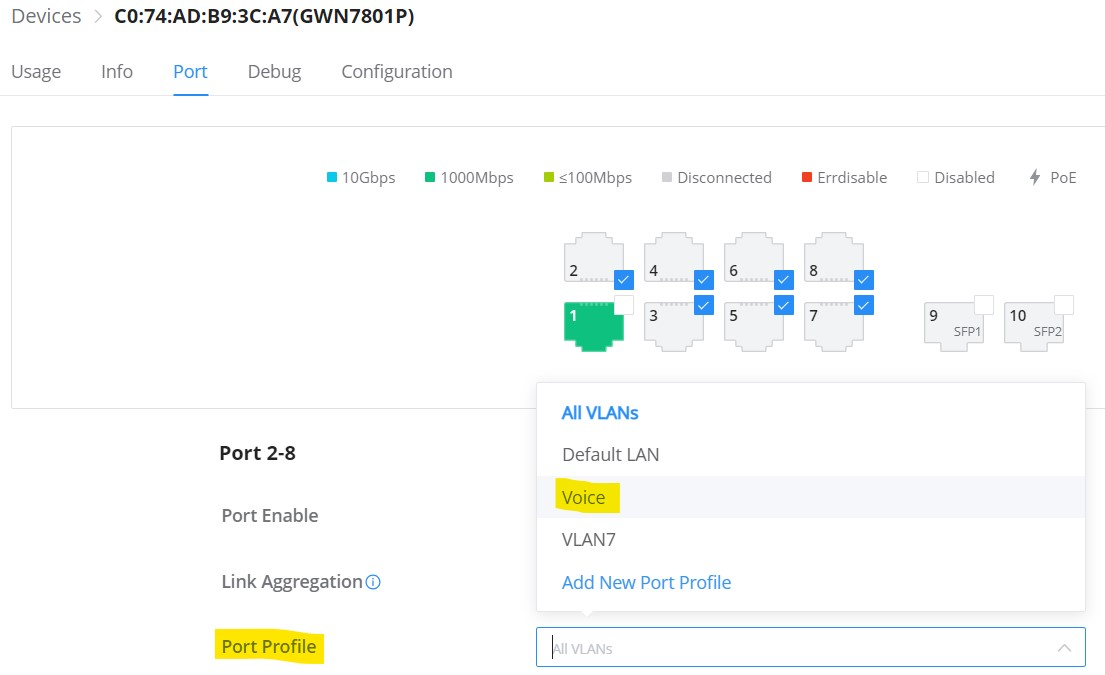
Mac Groups
The user can create a group of MAC addresses to be used on the SSID as a Whitelist or Blacklist for allowing or blocking clients. There is also the option to import a CSV file containing all the MAC addresses.
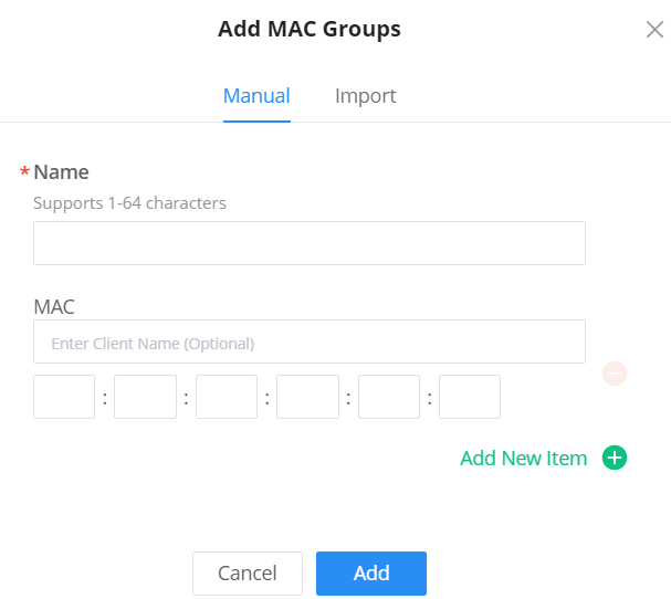
Bandwidth Rules
The bandwidth rule is a platform feature that allows users to limit bandwidth utilization per SSID or client (MAC address or IP address).
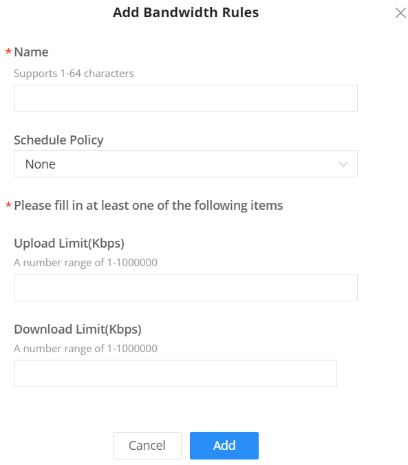
Schedule
A schedule can be created here to be applied in many places like rebooting or LED for example.
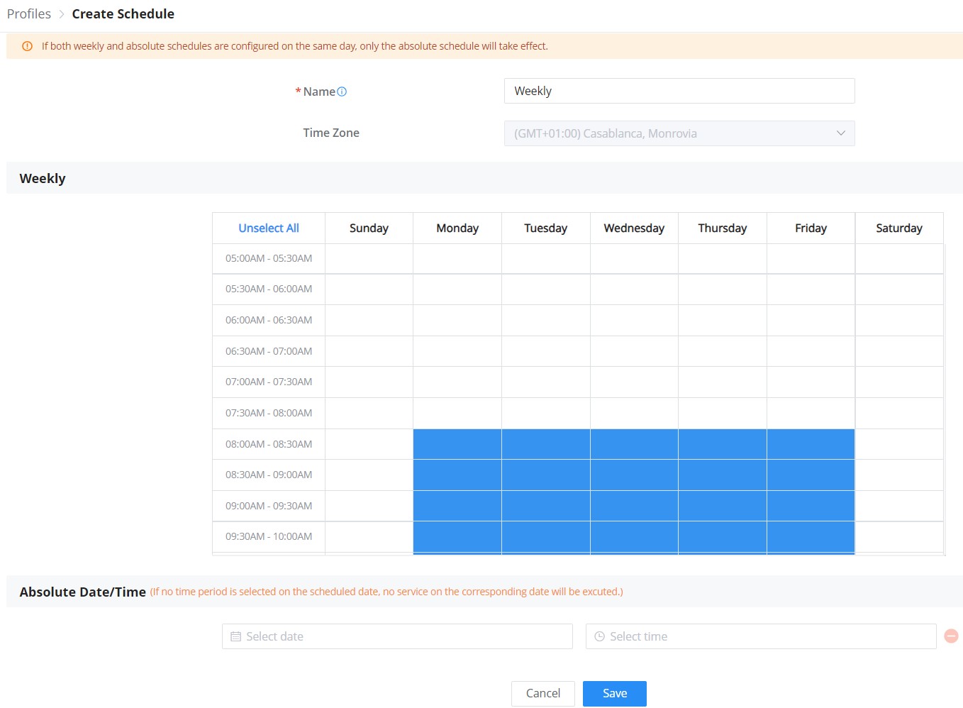
RADIUS
This page allows the user to add a RADIUS to be used in Portal policy or Wi-Fi security for example.
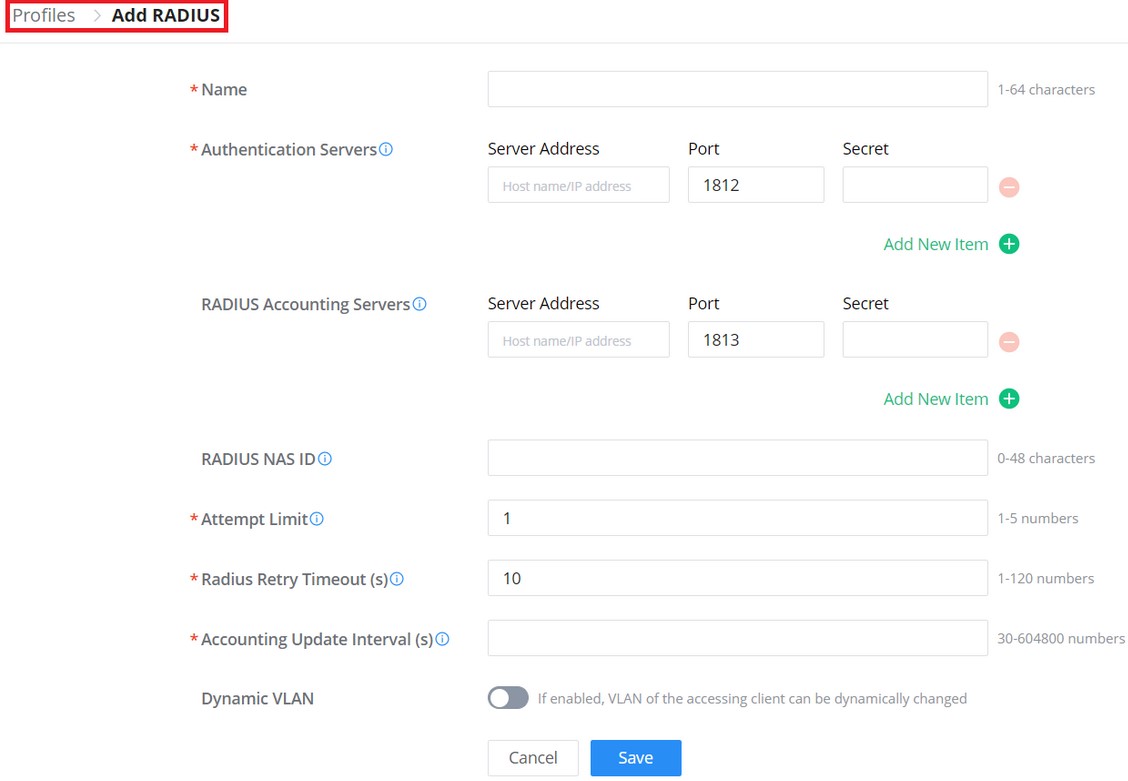
Private Pre-Shared Key (PPSK)
PPSK (Private Pre-Shared Key) is a way of creating Wi-Fi passwords per group of clients instead of using one single password for all clients.
To configure PPSK, please navigate to Web UI → Settings → Profiles → PPSK, then click on the “Add” button to add a new PPSK Group.
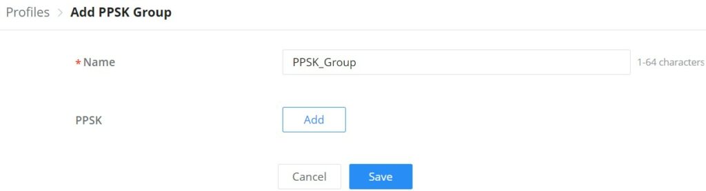
Give the PPSK Group a name, and after that click on the “Add” button to add a new PPSK.
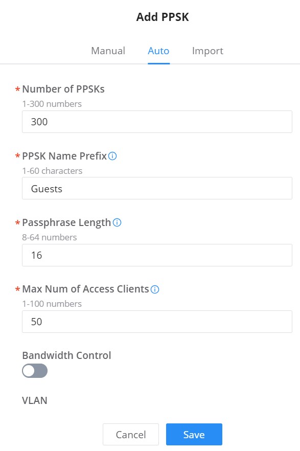
This is the result of the above configuration. 300 PPSKs have been created with a maximum number of access clients of up to 50.
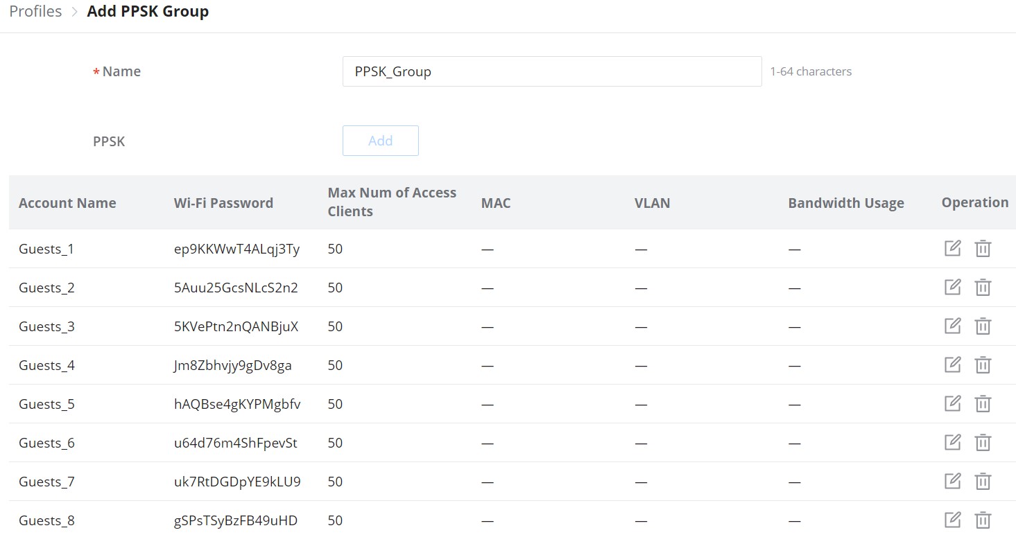
It’s also possible to manually assign a Wi-Fi password for a number of clients.
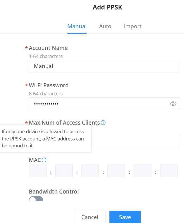
Another way is to upload a CSV file, please download the reference template.
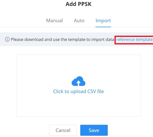
Now, the user can apply this PPSK group to any SSID, refer to the figure below:
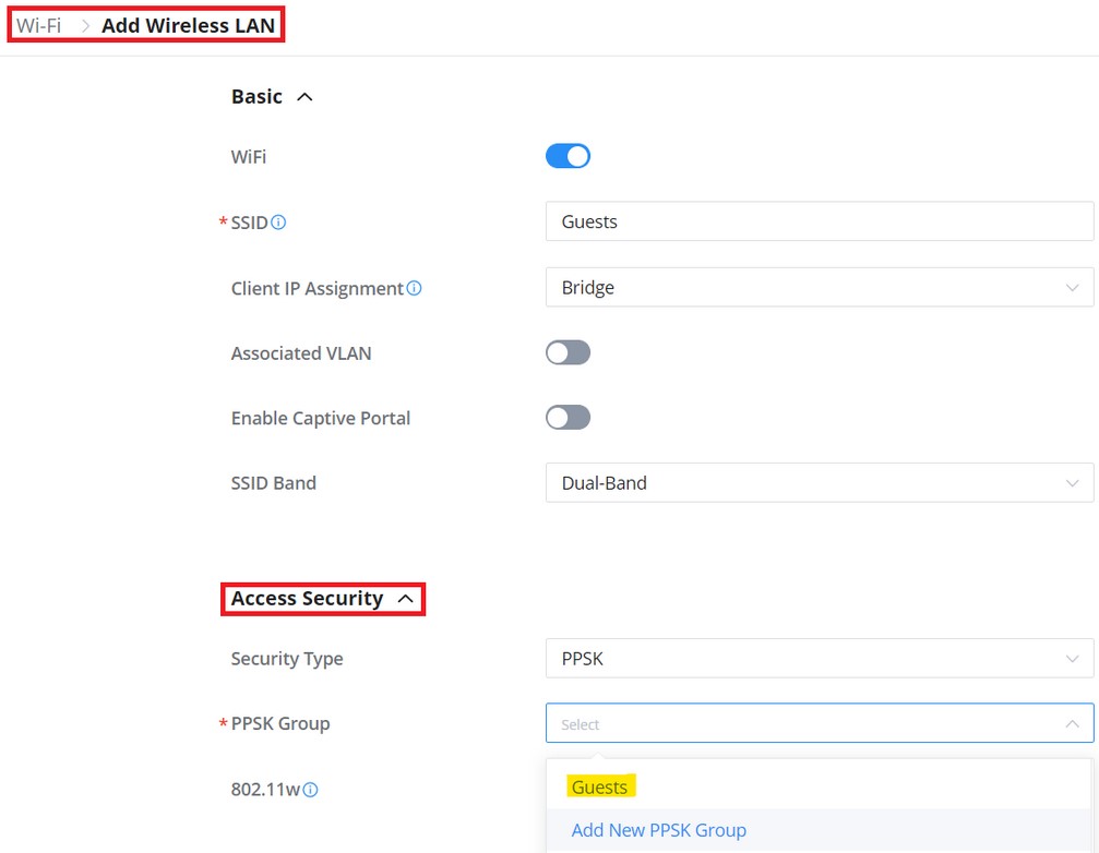
Certificates
In this section, the user can create CA, Client, and Server certificates that can be used with OpenVPN either for the client or server side.
The user can either click on the “Add” button to add a new certificate or click on the “Import” button to import them from his local machine to the GWN.Cloud or GWN Manager.
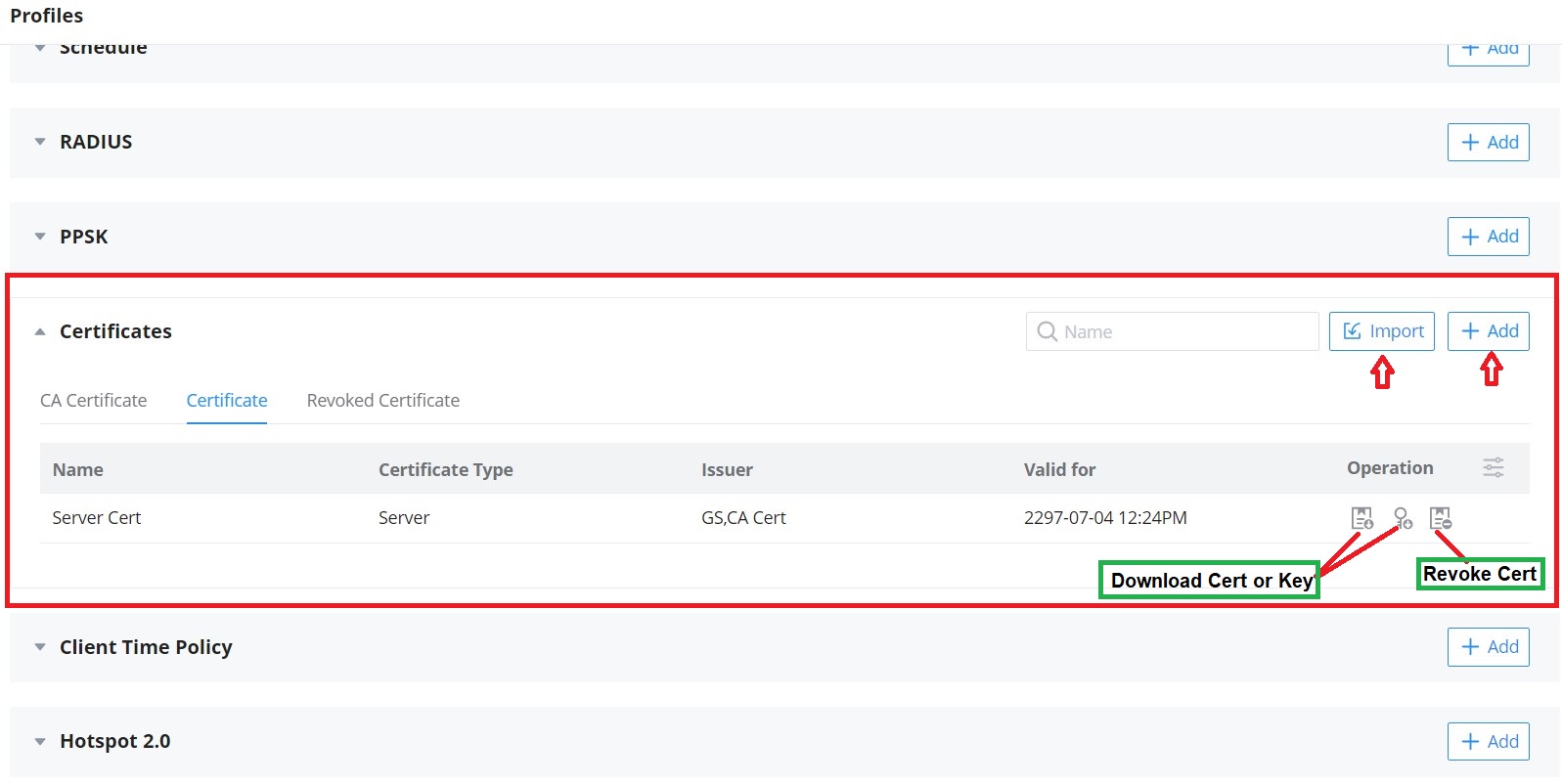
This page will be shown after clicking on the “Add” button, then the user can select between a CA Certificate or a Certificate which can be either for a Server or a Client based on the option “Certificate Type“. Please refer to the figures and tables below:
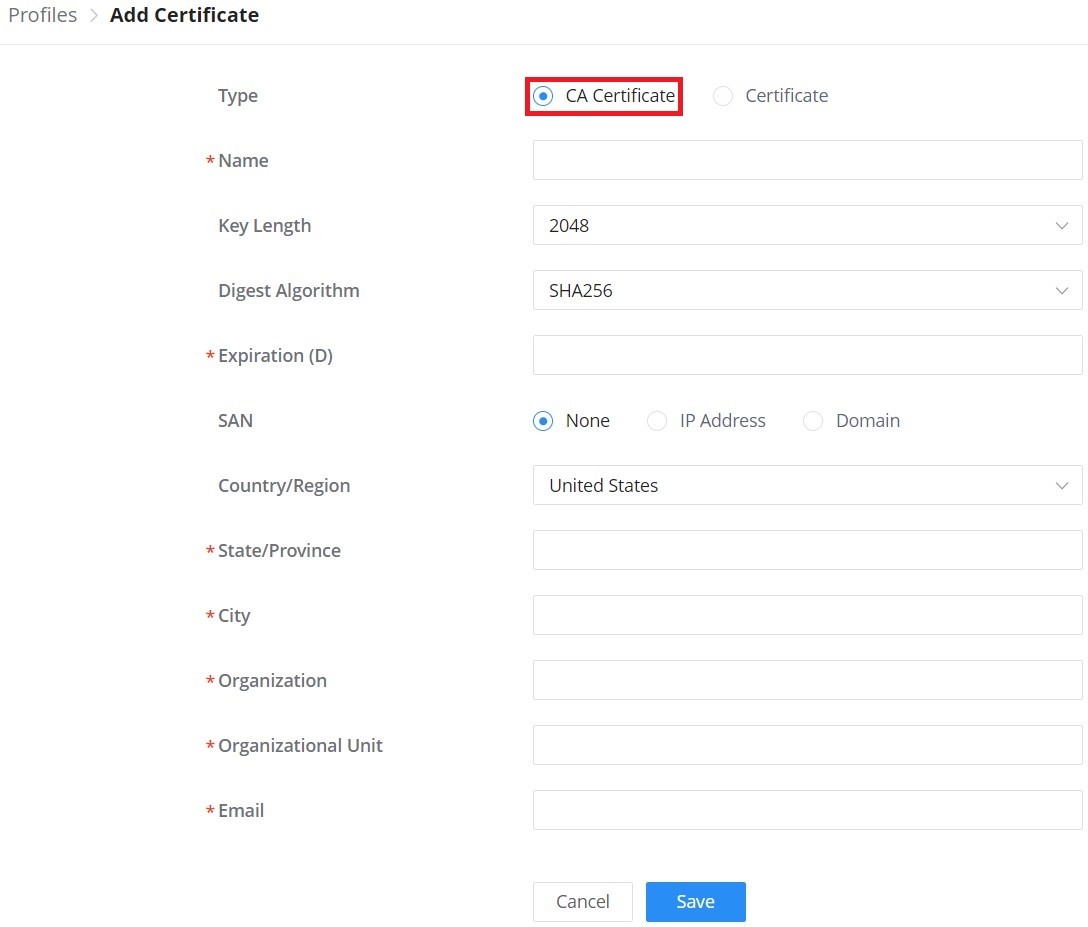
Type | Select the type of certificate either CA Certificate or Certificate. |
Name | Enter the certificate's name. |
Key Length | Choose the key length for generating the CA certificate.The following values are available:
|
Digest Algorithm | Select the digest algorithm.
Note: Hash is a one-way function, it cannot be decrypted back. |
Expiration (D) | Select the duration of validity of the certificate. The number entered represents the days that have to elapse before the certificate is considered as expired. The valid range is 1 - 999999. |
SAN | Enter the address IP or the domain name of the SAN (Subject Alternate Name). |
Country/Region | Select a country from the dropdown list of countries. Example: "United States of America". |
State/Province | Enter a state name or a province. Example: California |
City | Enter a city name. Example: "San Diego" |
Organization | Enter the organization’s name. Example: “GS”. |
Organization Unit | This field is the name of the department or organization unit making the request. Example: “GS Sales”. |
Enter an email address. Example: “EMEAregion@grandstream.com” |
Profiles – Add CA Certificate
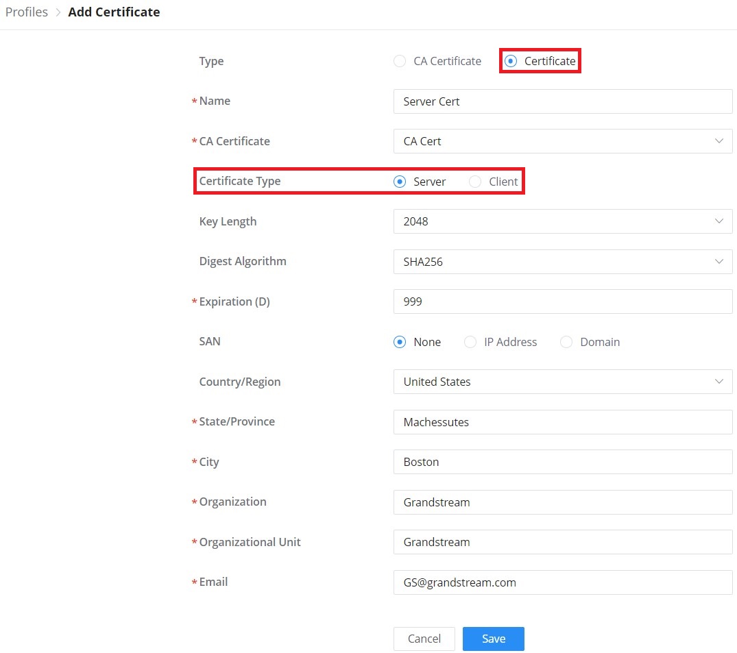
Type | Select the type of certificate either CA Certificate or Certificate. |
Name | Enter the certificate's name. |
CA Certificate | Select from the drop-down list the CA Certificate previously created. |
Certificate Type | Select the certificate type either a server or a client certificate. |
Key Length | Choose the key length for generating the CA certificate.The following values are available:
|
Digest Algorithm | Select the digest algorithm.
Note: Hash is a one-way function, it cannot be decrypted back. |
Expiration (D) | Select the duration of validity of the certificate. The number entered represents the days that have to elapse before the certificate is considered as expired. The valid range is 1 - 999999. |
SAN | Enter the address IP or the domain name of the SAN (Subject Alternate Name). |
Country/Region | Select a country from the dropdown list of countries. Example: "United States of America". |
State/Province | Enter a state name or a province. Example: California |
City | Enter a city name. Example: "San Diego" |
Organization | Enter the organization’s name. Example: “GS”. |
Organization Unit | This field is the name of the department or organization unit making the request. Example: “GS Sales”. |
Enter an email address. Example: “EMEAregion@grandstream.com” |
Profiles – Add Certificate (Client or Server)
Client Time Policy
The administrator can configure a Time policy that will dictate how much a client connects to the Wi-Fi if this policy is applied for the SSID.
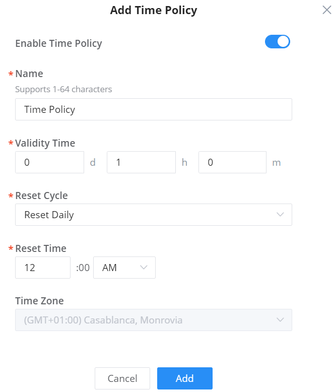
| Enable Time Policy | Check/Uncheck to Enable/Disable Policy |
| Name | Enter a name to identify the Policy. Supports 1 to 64 characters, including numbers, letters, and special characters. |
| Validity Time | Configure the policy duration from 1 minute to 365 days. |
| Reset Cycle | Set up a Reset mode: Daily, Weekly, or Periodically |
| Reset Time | When the Reset Cycle is Daily: configure the time of the day. When the Reset Cycle is Weekly: configure the time and the day of the week When the Reset Cycle is Periodic: configure the period (d//h/m) |
| Time Zone | Detected Automatically. This parameter can be changed under System Settings |
Hotspot 2.0
Hotspot 2.0, also known as HS2.0 or Passpoint, is a set of industry specifications developed by the Wi-Fi Alliance to improve the connectivity and user experience of Wi-Fi networks, particularly in public places. The goal of Hotspot 2.0 is to make Wi-Fi connectivity as seamless and secure as cellular networks.
Key features of Hotspot 2.0 include
- Automatic Authentication: Hotspot 2.0 enables automatic and secure connection to Wi-Fi networks without user intervention. Devices can automatically connect to Wi-Fi hotspots, similar to how cellular networks work.
- Seamless Roaming: With Hotspot 2.0, users can roam between different Wi-Fi networks without having to re-authenticate. This is especially useful in environments with multiple Wi-Fi access points, such as airports, shopping malls, and other public spaces.
- Passpoint: Passpoint is a specific implementation of Hotspot 2.0 that allows mobile devices to automatically discover and connect to Wi-Fi networks that are part of the Passpoint ecosystem. Passpoint provides a streamlined and secure connection process, making it easier for users to connect to Wi-Fi hotspots.
Hotspot 2.0 is particularly relevant in environments where reliable and secure Wi-Fi connectivity is essential, such as airports, hotels, and other public spaces. It improves the overall user experience by making Wi-Fi connectivity more like cellular connectivity, with automatic authentication and seamless roaming.
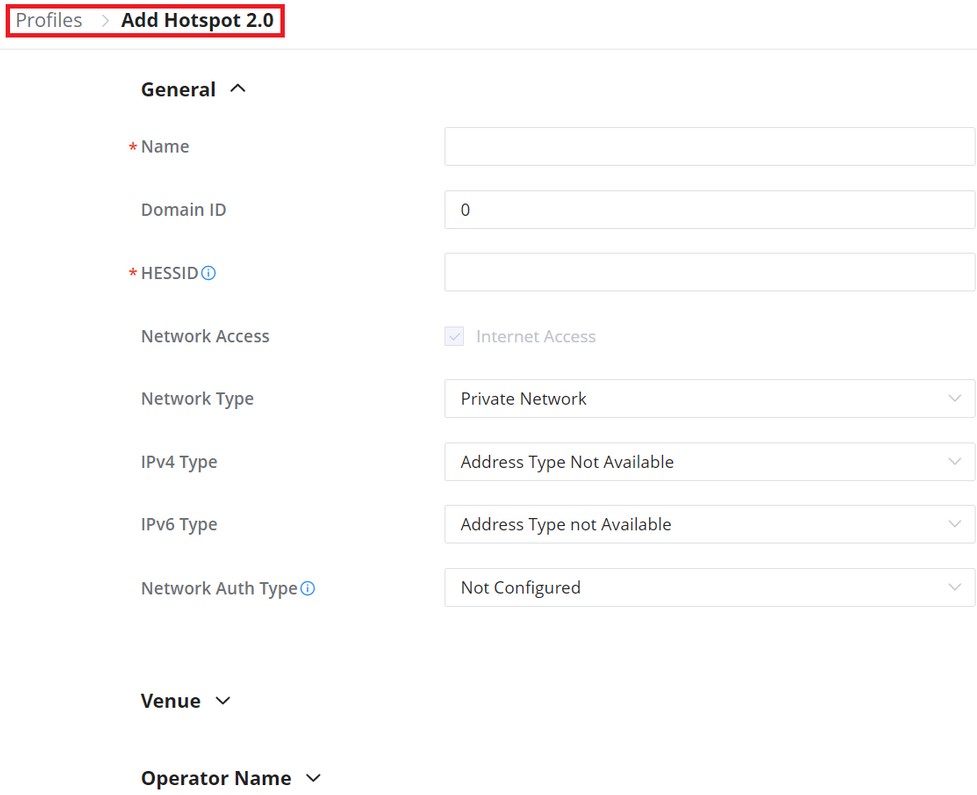
SYSTEM
General
Navigate to Web UI → Settings → System → under General to configure General settings like Country/Region, Time zone, Time, LED, Reboot Schedule, etc.
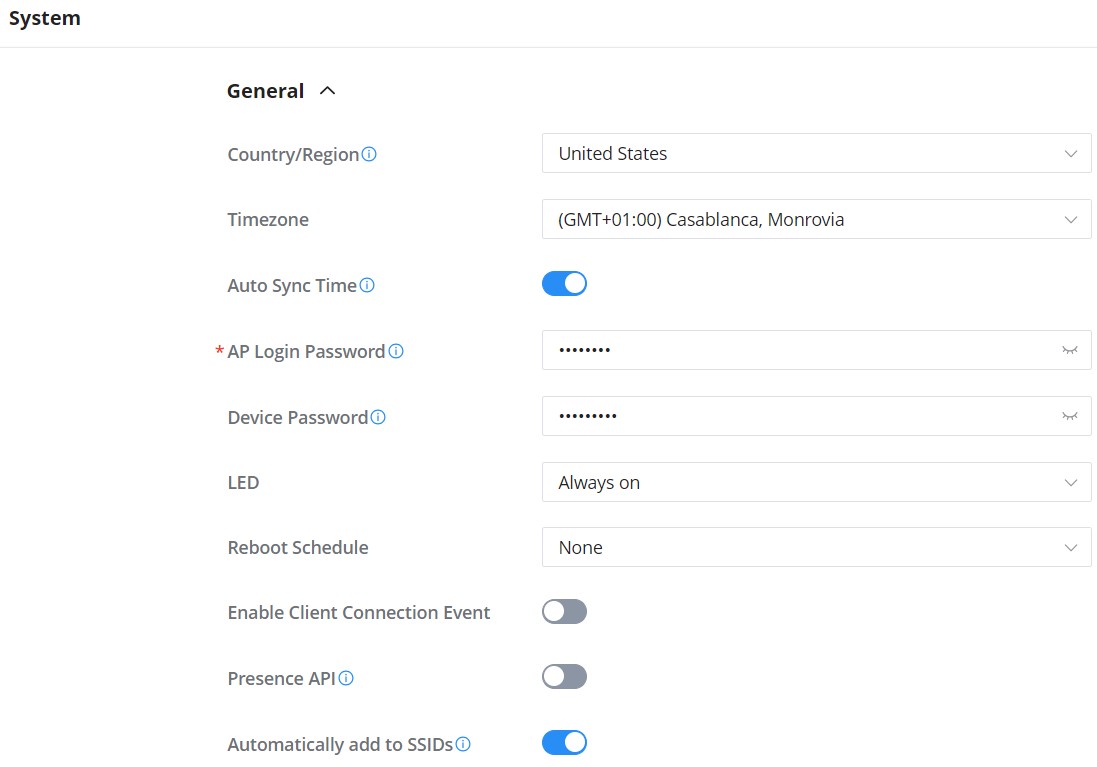
Country/Region | Select the country or region from the drop-down list. This can affect the number of channels depending on the country standards. |
Timezone | Configure time zone for GWN APs. Please reboot the device to take effect. |
Auto Sync Time | If enabled, all managed devices' system times will be synced with GWN Cloud |
AP Login Password | Sets the APs login password with up to 8 characters. Alphanumeric characters and special characters - _ | are supported |
Device Password | Set the devices SSH remote login password other than APs (Routers and Switches), which is also the device web login password. |
LED | Select whether to always turn ON or OFF the LEDs on the APs or apply a schedule for this function. |
Reboot Schedule | Once scheduled, the current network will not work for a while during the scheduled period. |
Enable Client Connection Event | When enabled, then Client connects/disconnects events are listed under Devices → GWN device → Info page. |
Presence API | Onced enabled, will detect and collect wireless device info. near the AP, which can be used for device positioning, pedestrian flow monitoring and so on. |
Automatically add to SSIDs | GWN devices will be added to SSID automatically |
System page – General
URL Access Log
Administrators can easily configure the platform to record, monitor, and maintain a log of all the websites visited by the clients connected to the paired GWN devices.
The platform System will send these logs via Email to the configured Log Receiver in the form of a downloadable link providing a CSV file format containing all the website logs visited for each client during the defined period (daily, weekly, or monthly basis).
To enable this feature, follow the below steps:
- Go under “Settings → System page → URL Access Log section” and enable the URL Access Log field, this will configure the GWN Manager System to start recording the website logs visited by the clients.
- The option “Group Metric by Main Domain” can be also enabled then the user can configure the top domains to be merged. This will merge the page views for the configured domains. The regular top domains will automatically merge without any configuration (such as. com).
- Enable Export URL Access Log.
- Administrators can choose to set the Email Frequency to be generated either on a daily, weekly, or monthly basis.
- Configure the URL Log Receiver Email.
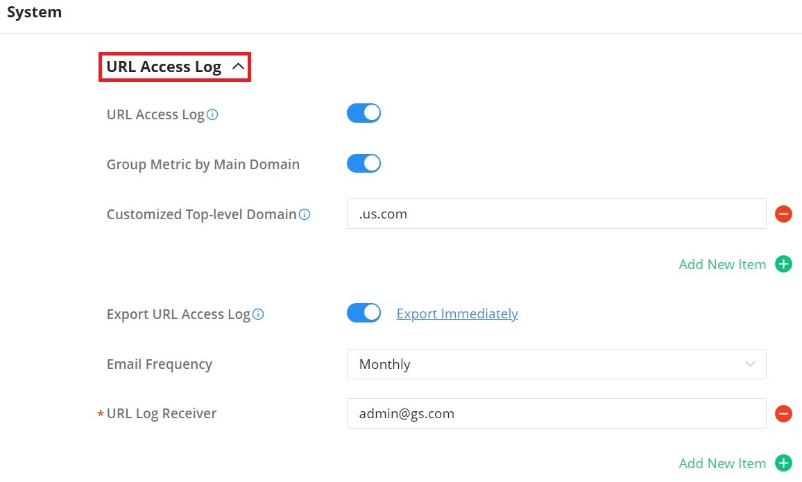
In this example, the administrator will start receiving, every week, an Email containing a downloadable link providing a CSV file containing the websites visited by the clients during the last day.
Users can click on “Export Immediately”, and then specify the time range of the URL Access Log during the last (1 – 30) days to be exported immediately.
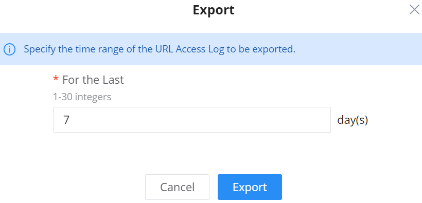
5. Click on the “Export” button and notice the success confirmation message:

- Click the highlighted link to Download the log file and save it locally.
Once downloaded, administrators will have a CSV file tracking the Internet activity for all the clients connected to the paired GWN devices.
The CSV file will contain columns displaying the AP MAC address, the client’s hostname as well as the device MAC address, the Source and Destination IP, the URL logs, the HTTP Method (GET/POST), and the time of request.
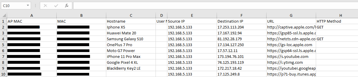
Guest Information
If enabled, the cloud server will periodically send out the log download link based on the configured email settings. To enable this feature, follow the below steps:
- Go under “Settings → System page → Guest Information section“ and enable the Guest Information field.
- Choose to set the Email Frequency to be generated either on a daily, weekly, or monthly basis.
- Configure the Email Receiver.
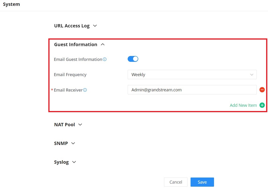
NAT pool
Users can use this feature to set an address Pool from which the clients that are connected to the adopted/paired devices will acquire their IP address in that way GWN devices will act as a lightweight router.
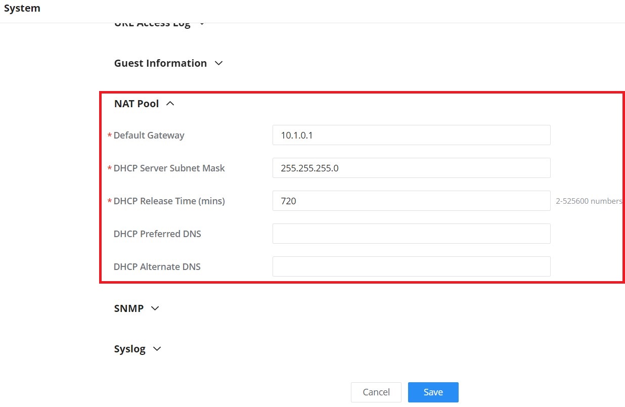
Navigate to Web UI → Settings → System page (NAT Pool section), to configure the Gateway, DHCP Server Subnet Mask, DHCP Lease Time, and DHCP Preferred/Alternate DNS.
SNMP
This section lists the SNMPv1, SNMPv2c, and SNMPv3 options available to integrate the adopted/paired GWN devices with enterprise monitoring systems.
Users can enable the SNMP feature under Web UI → Settings → System page (SNMP section).
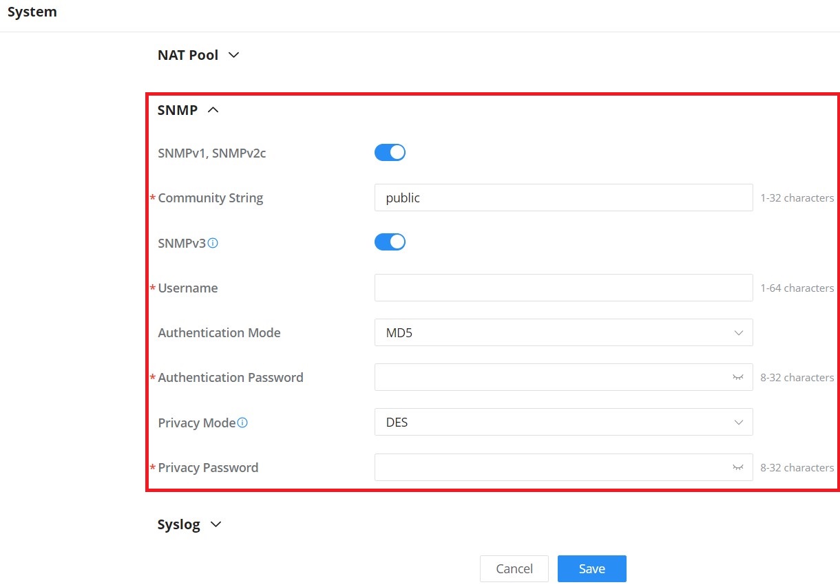
SNMPv1, SNMPv2c | Enable Enable SNMPv1/SNMPv2c. |
Community String | Enter the SNMP Community string. |
SNMPv3 | Enable SNMPv3. Note: If the SNMPv3 function of the switch is required to work, SNMPv1 and SNMPv2c should be enabled at the same time. |
Username | Enter the SNMPv3 username. |
Authentication Mode | Set the Authentication mode to: either MD5 or SHA. |
Authentication password | Enter the SNMPv3 authentication password. |
Privacy Mode | Set the Privacy mode to: either AES128 or DES. Note: AES128 mode is only for routers and APs. Switches use DES mode. |
Privacy password | Enter the privacy password. |
SNMP
Syslog
Configure Syslog settings to have GWN devices sending log messages to your debugging Syslog server. There are two options, either to use the built-in GWN.Cloud syslog server or a Local syslog server and in this case the user will have to enter the local syslog server address.
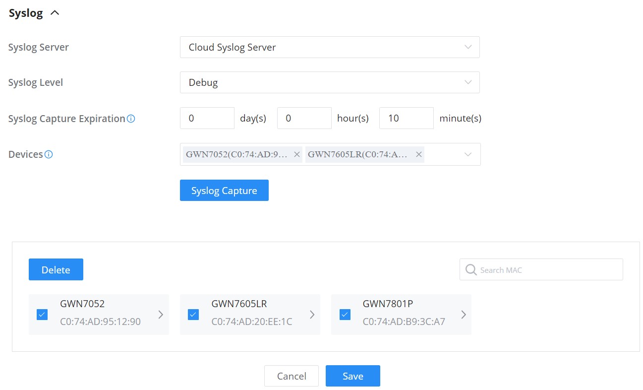
Syslog Server | Select the syslog server from the list:
|
Local Syslog Server Address | Enter the IP address or URL of the syslog server. |
Syslog Level | Select the level of Syslog, 8 levels are available: None, Emergency, Alert, Critical, Error, Warning, Notice, Information and Debug |
Protocol | Sets the protocol used by the system log server. Default port for both UDP and TCP is 514. |
Devices | Select the devices to capture syslogs from |
Syslog
ORGANIZATION
Overview
Network Overview
The overview page offers a bird’s-eye look at all the GWN devices that have been added to the organization. This includes GWN routers, GWN switches, GWN APs, and clients. In addition to that, the user can see the number of networks created by that organization and the number of administrators in the organization.
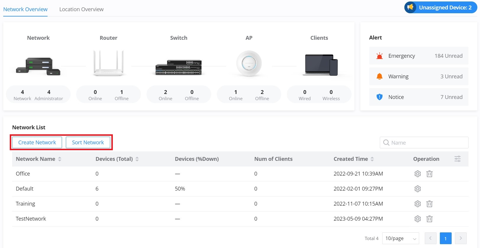
- Click on the “Create Network” button to create a new network.
- Click on the “Sort Network” button to sort network order, the first one on the list will be the primary network (the network that will be selected after a login).
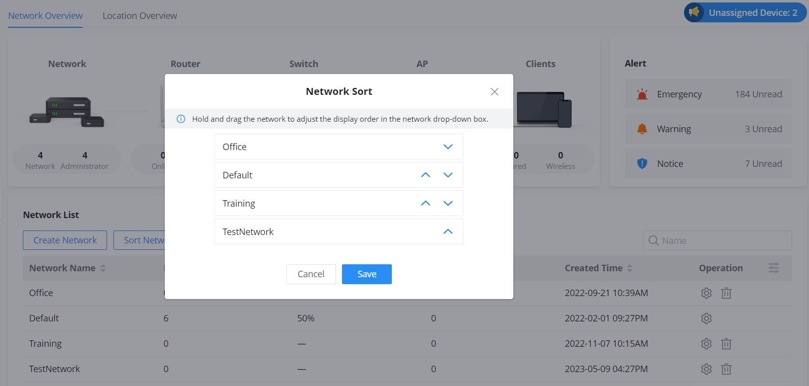
Inventory
The inventory page lists all the GWN devices in all networks, including online and offline ones. Click on a device to be redirected to the Devices page for more options.
On this page, the user can see each GWN device-related information: model, MAC address, network, serial number, claim time, assigned time (and which network it has been returned from), and last seen.
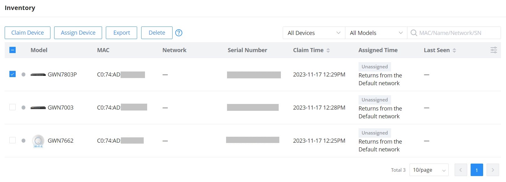
The user can click on the “Export” button to export a CSV file containing all the GWN devices.
- Claim Device: to claim a device (GWN device MAC address and Password is required) even if the GWN device is offline, it will not be assigned to any network.
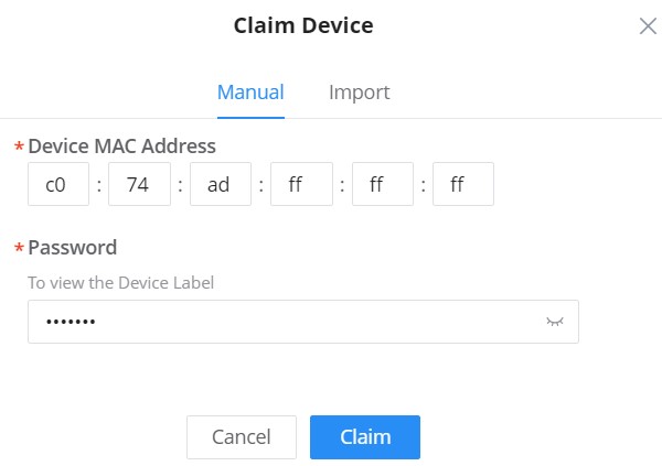
- Assign Device: to assign the device to the network (it will added to the selected network).
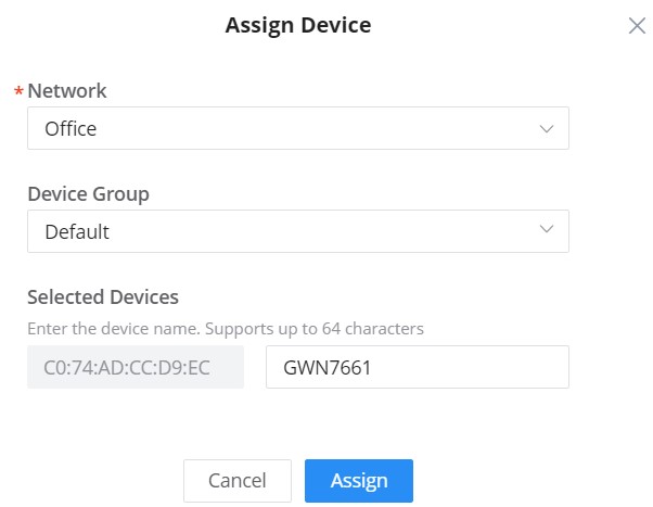
- Export: to export a CSV file containing all the GWN devices.
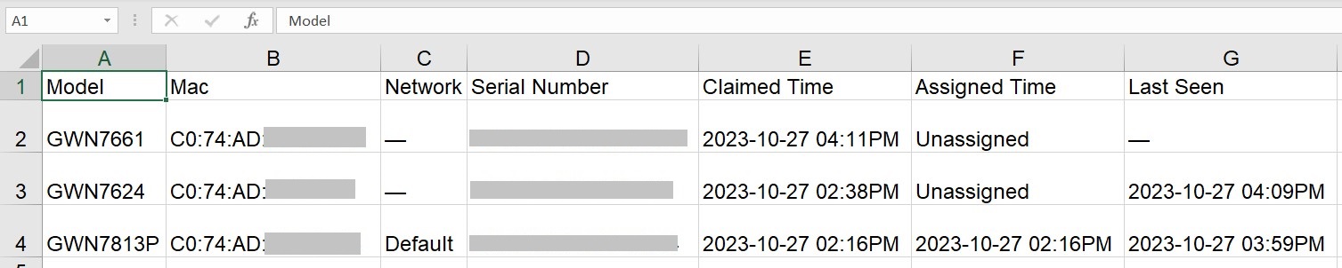
- Delete: to delete a device from the GWN management platform.
Reseller Channel
Reseller Channel will be able to support the establishment of the hierarchy agent partnership, retrieve device from ERP, and assign device to network groups or channels/agents:
- Support first-level channel or agent to bind the ERP ID and sync the device.
- Support assigning/returning/reclaiming device to network or associated company.
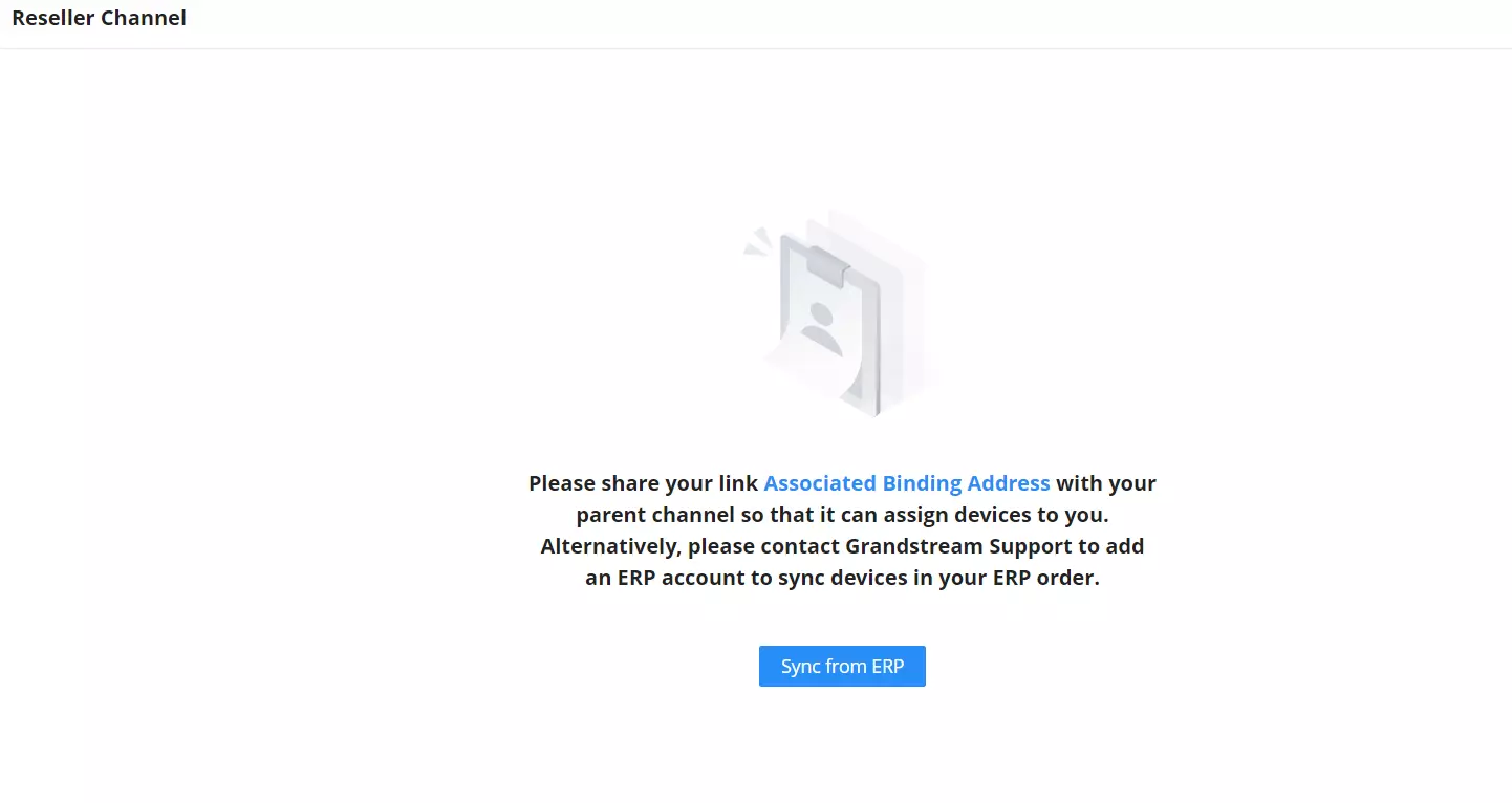
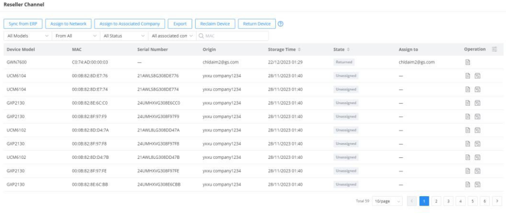
Users
User Management allows the administrators to create multiple accounts for different users to log in to the platform. There are 6 base different access levels to monitor and manage GWN devices, it’s also possible to create a custom role with custom privileges.
- Super Administrator (the initial administrator)
- Platform Administrator
- Platform Administrator (Read Only)
- Network Administrator
- Network Administrator (Read Only)
- Guest Editor
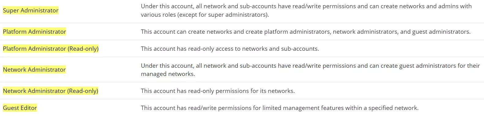
Add New User
To add a new user, navigate to Organization → Users → User page, then click on “Add” button to add a new user. Then specify the nickname, email address, Role, and the networks allowed to be accessed by this user in all regions, there is also the option to enable multi-factor authentication or to add the user to newly created networks automatically.
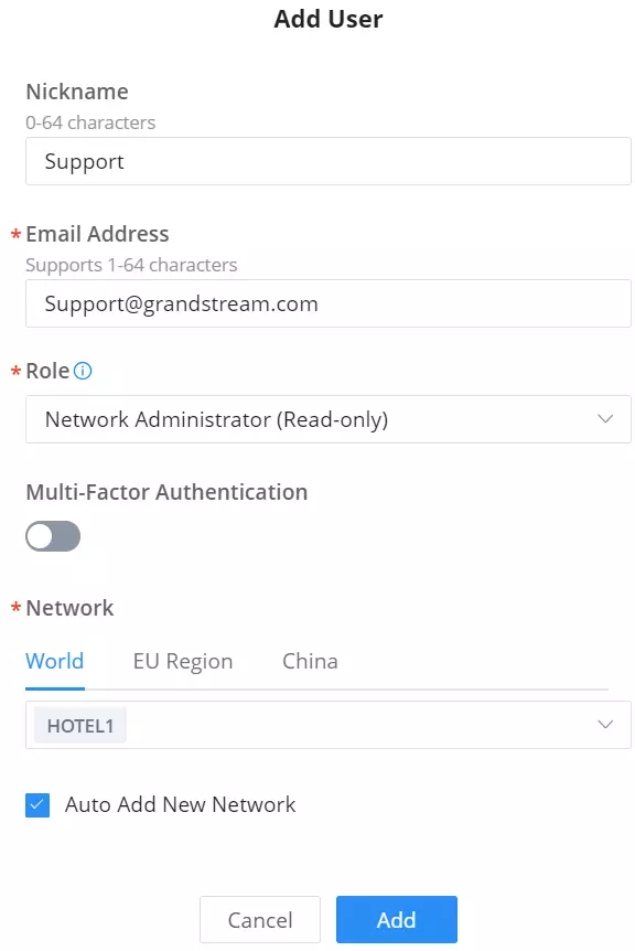
Roles
In addition to the roles predefined, the user can add a custom role and choose which privileges to assign to the role. To add a new role, please navigate to Organization → Users → Roles, then click on “Add” as shown below:
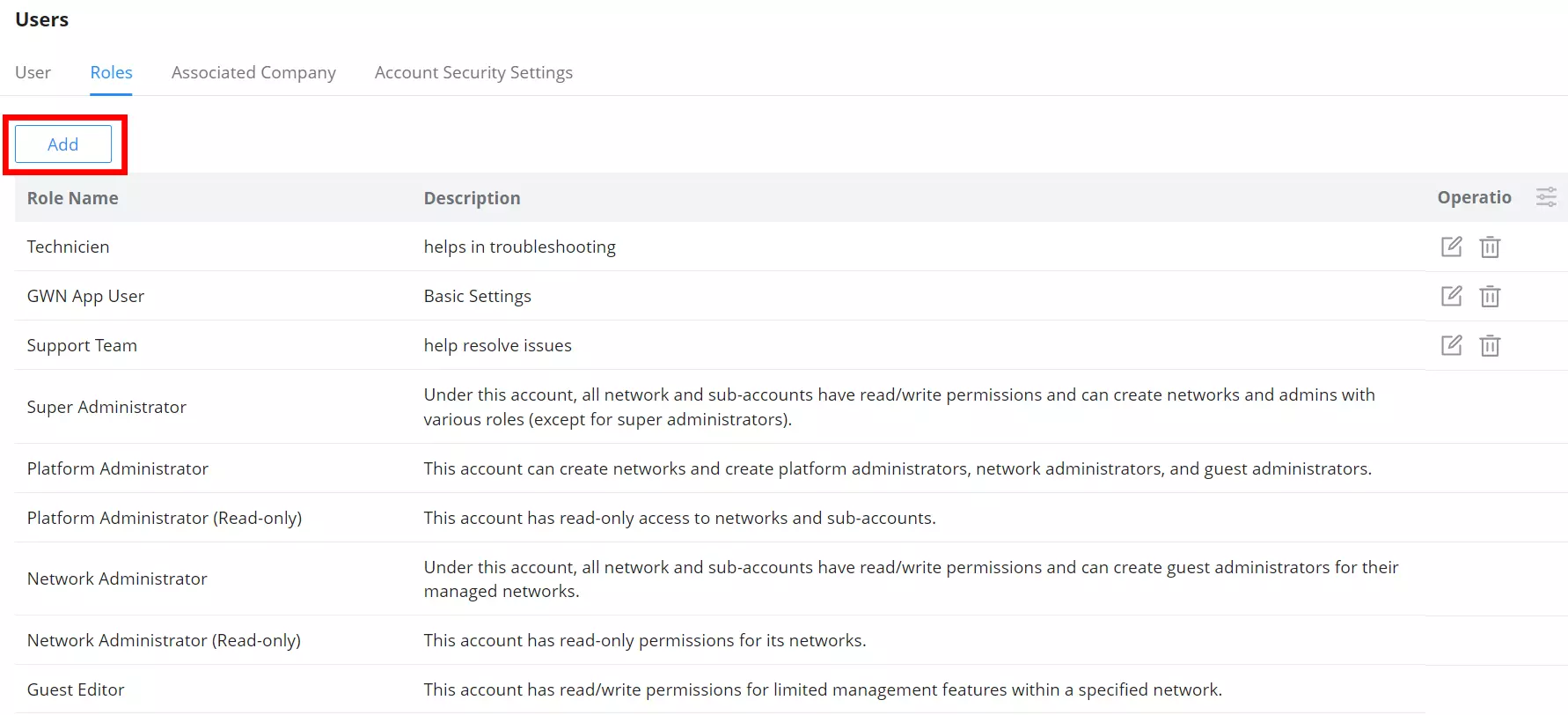
Under “Organization” tab, select the organization privileges for this user.
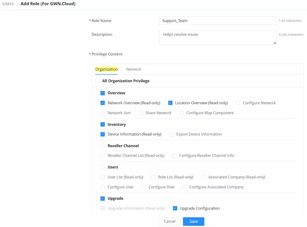
Under “Network” tab, select the network privileges for this user.
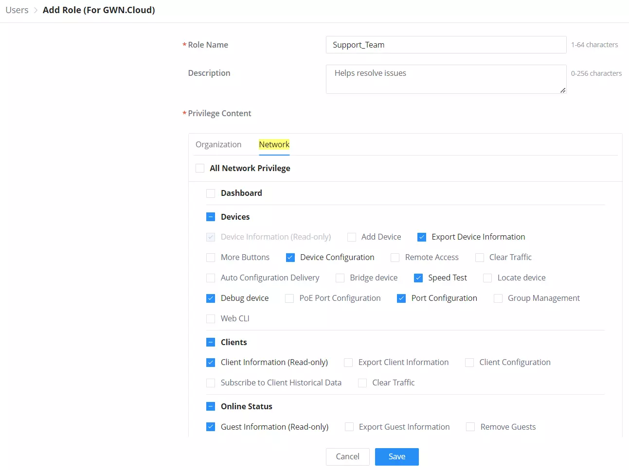
Then create a new user account and assign the new role to it.
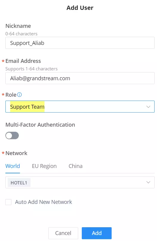
Associated Company
Users can add other accounts, such as sub-channels and customers, as Associated Companies. They can then share their network with them under the user name or assign devices to them.
Navigate to Organization → Users → Associated Company, then click on “Add” button to add an associated company.
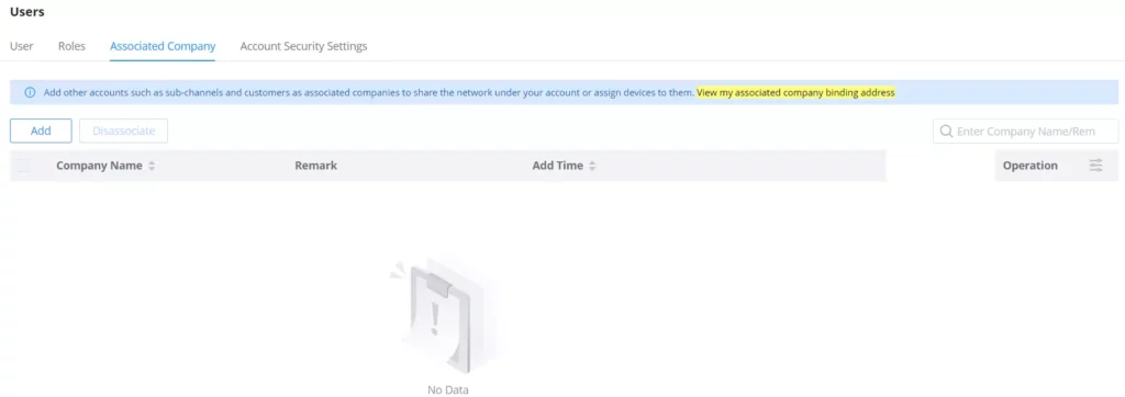
To add an associated company, the associating address is required, and it can be found under Organization → Users → Associated Company, then click on “View my associated company binding address” as shown above.
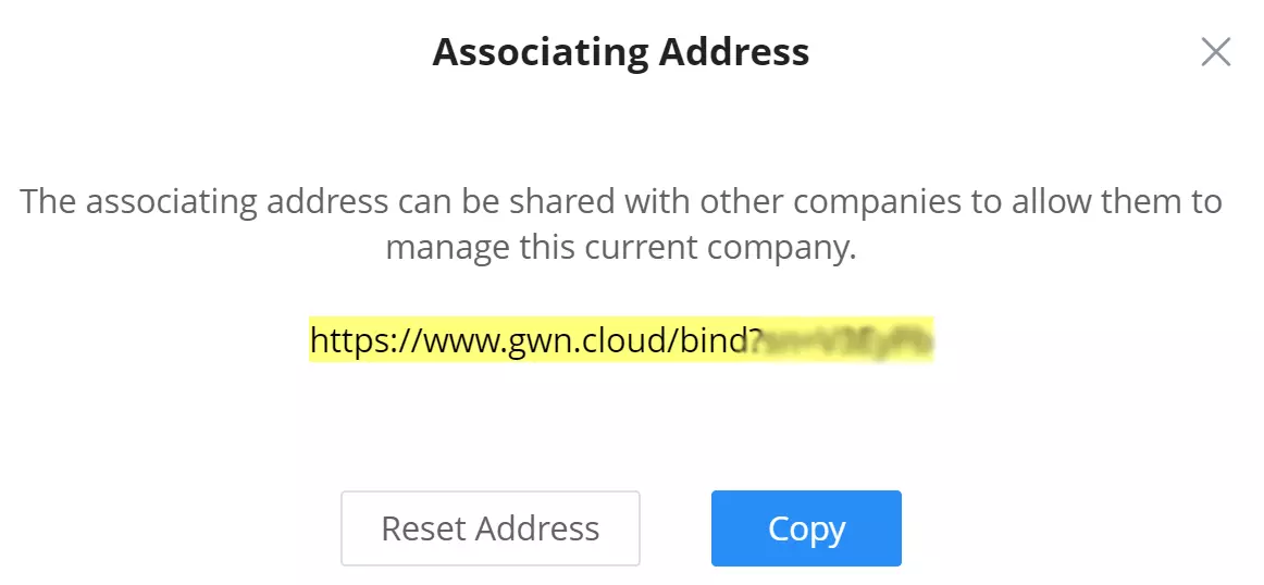
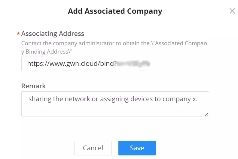
Once the associated company is added, devices under Organization → Inventory can be assigned to the newly added associated company, as shown in the example below:
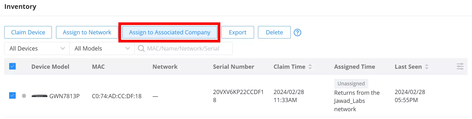
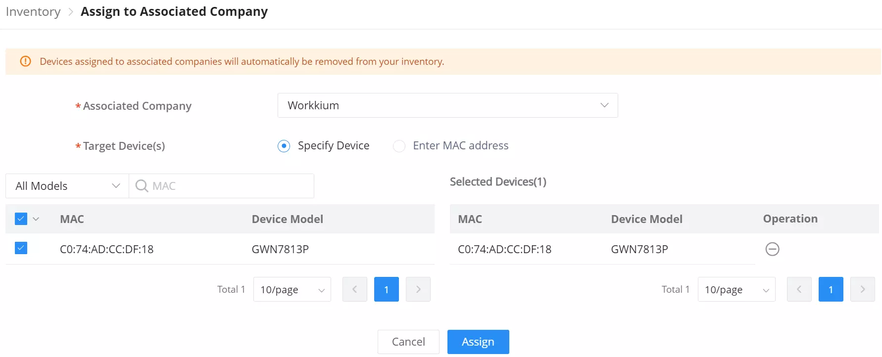
It’s also possible to share an entire network with an associated company under Organization → Overview (the default network can’t be shared with an associated company). Please check the example below:
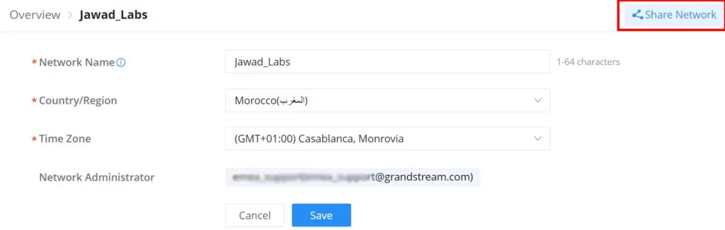
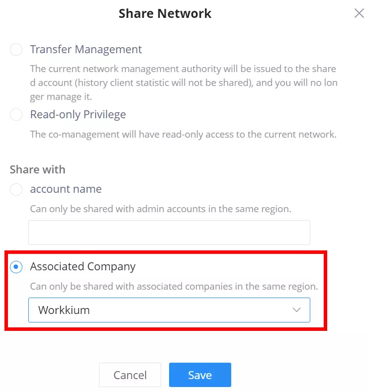
Account Security Settings
To enhance GWN.Cloud security, users can enable Password Security and with this option the users can set a password expiration period (days) where the password must be changed and even not be the same as the previous one(s). Also account idle timeout and login duration can be configured here (minutes). Multi-Factor authentication can be enabled on all accounts.
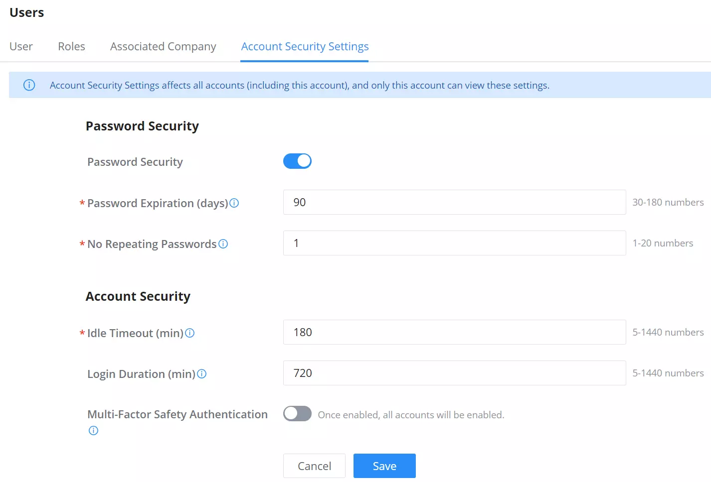
Password Security | |
Password Security | Toggle on/off the password security. |
Password Expiration (days) | Specify the number of days of validity of a password. Once the number of days configured has elapsed, the user will be prompted to change his/her password upon login. |
No Repeating Passwords | Settings this option will prevent the user from using a password which he/she had previously used. You can set the number of previous passwords which have been used to prevent them from being used again as a new password. |
Account Security | |
Idle Timeout (min) | This configures the number of minutes of a user being idle on the web GUI before he/she can be automatically logged out by the system. The user can enter a value from 5 to 1440 minutes. Configuring this value is required. |
Login Duration (min) | This configures the number of minutes a login session can last before the user is logged out automatically by the system. The user has to log in again to start after being logged out. Note: The user can enter a value between 5 and 1440 |
Multi-factor Authentication | If MFA is enabled, all accounts (including this account) will be required to use multi-factor authentication. This cannot be disabled by other users. If disabled, users will be able to toggle MFA for their own accounts. |
Account Security Settings
Upgrade
Devices Upgrade
This feature allows upgrading GWN devices. Under “Upgrade” menu allows the administrator to manage GWN devices’ firmware, and trigger immediate upgrades or Upgrade reminders. There is also the option for Upgrade History on the second tab.
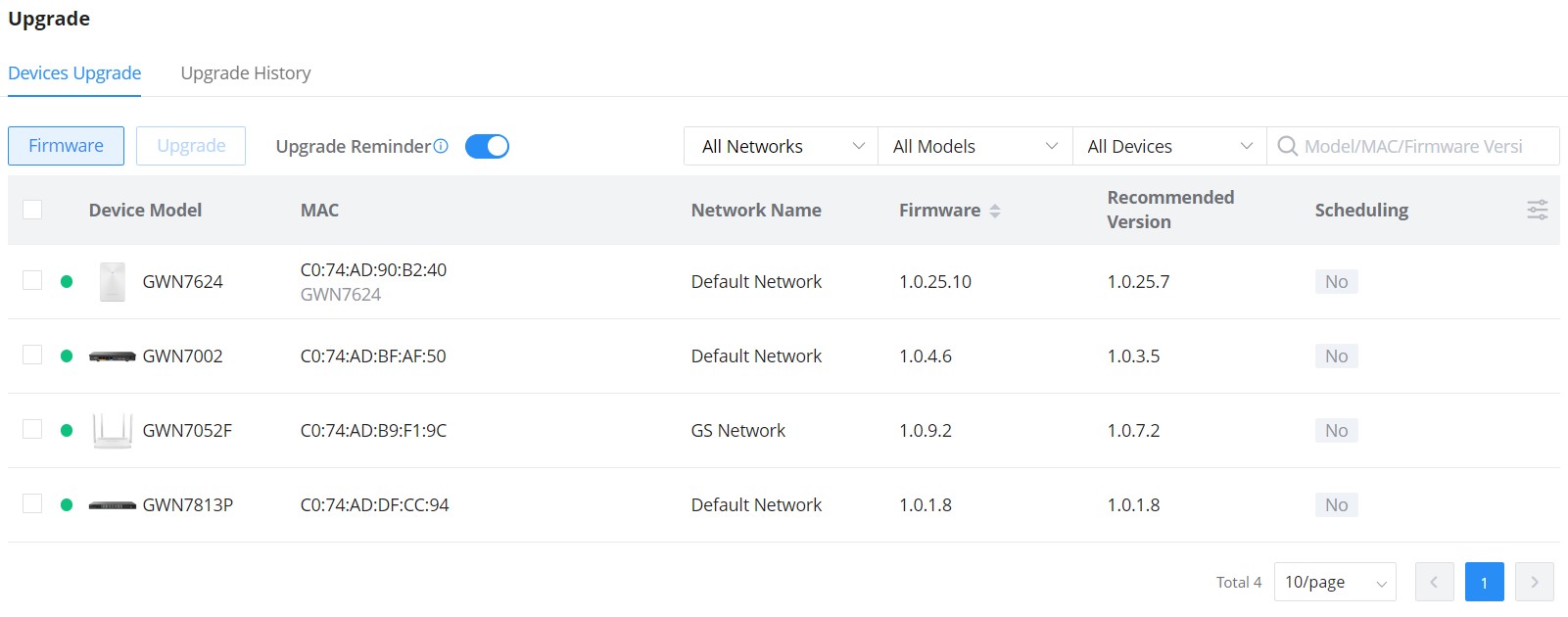
Select the devices you wish to upgrade then click “Upgrade“. Under “Firmware Version” the users can select which version to upgrade to (Beta Firmware is also supported but not recommended).
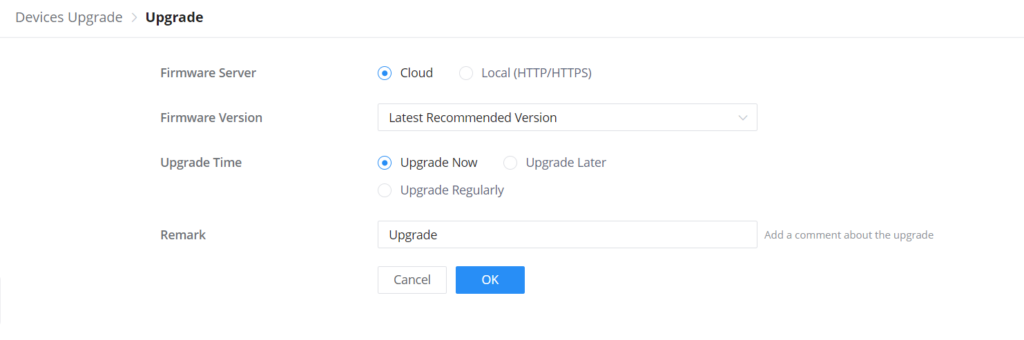
Manager Upgrade
The users can upgrade the GWN Manager directly from the Web UI, by navigating to Organization → Upgrade page → Manager Upgrade tab.
On this page, the users can see the current version and the latest firmware available, to upgrade to the latest firmware, please click on “Upgrade” button as shown below:
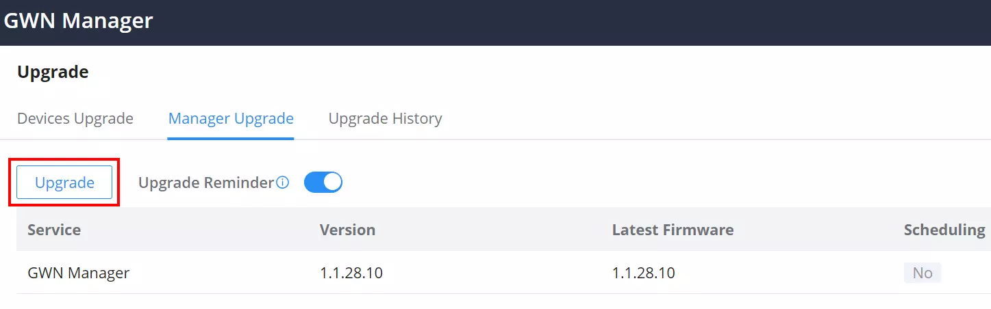
The users have the option to upgrade now, upgrade later or upgrade regularly, a remark or comment about the upgrade can be also added. The overall features related to the upgrade will be listed under.
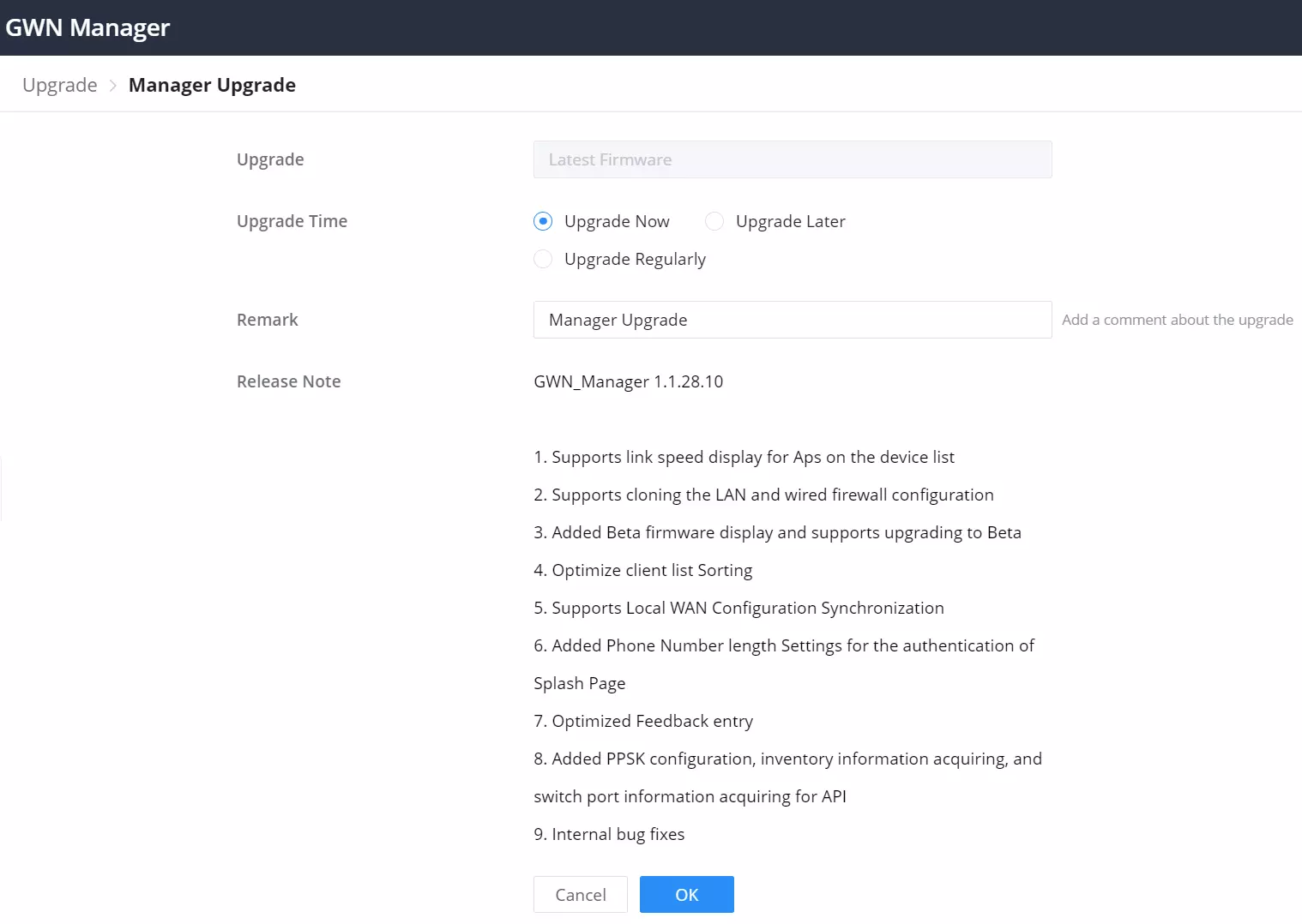
Upgrade History
On the upgrade history tab, the user can see the upgrade history of all GWN devices with details information like (device model, firmware version, upgrade status, etc), it’s also possible to search for a device using its MAC address.
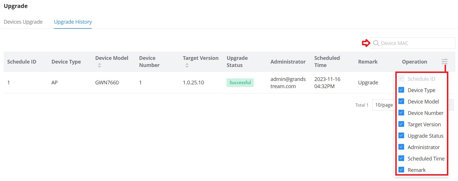
Report
Administrators can generate and configure the platform to send reports periodically to the configured email addresses. Each report can be related to one or more different Network groups, providing Wi-Fi statistics (client count, bandwidth usage, client and guest statistics…etc.)
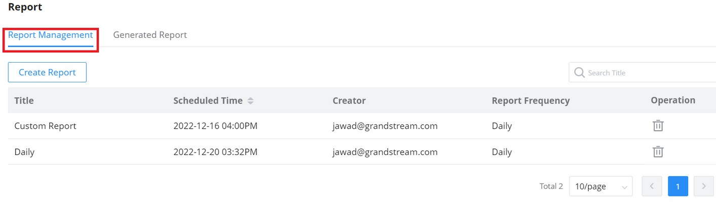
To generate the report, click on the “Create a Report” button, and a new page displaying the report details will be displayed.
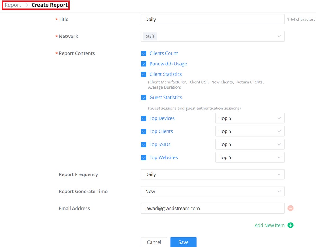
The following table explains different options for report settings:
| Field | Description |
| Title | Specify the report title. The maximum length is 64 alphabet characters. |
| Network | Specify the Network Group to be included in the generated report. Note: The maximum number of network groups that can be selected is 100. |
| Report Contents | Specify the report contents for the selected network group(s), the contents can include: • Clients Count: reports the number of clients for all the SSIDs under the selected network group. • Bandwidth Usage: The download and upload level statistics for all the SSIDs for the selected network group • Clients Statistics: reports the statistics for the different client manufacturers, client OS, the number of new clients as well as the return clients, and the average duration. • Guest Statistics: reports statistics about the clients connected via the Captive portal including the Guest New session, the Max concurrent New session, and the login failure. • Top Devices: reports the top 5/20/50 devices that consumed the max of the bandwidth/data. • Top Clients: Lists the top 5/20/50 clients that downloaded/uploaded the max of data • Top SSIDs: reports the top 5/20/50 SSIDs that are mostly used by clients. • Top Websites: reports the top 5/20/50 websites that are mostly visited by clients. |
| Report Frequency | Specify the report frequency to be generated either daily, weekly, monthly, or custom range. |
| Date | Specify the Start and Date for the report to be generated when selecting “Custom Range” as Report Frequency. |
| Report Generate Time | Select either to generate the report now or at a later time |
| Time | Specify when you want the report to be generated. This field appears when selecting “Later” in “Report Generate Time”. |
| Email Address | Enter the mail address(es) to which the report will be sent. |
Organization Change Log
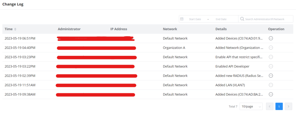
To see more details, click on the three dots.
API developer
Third-party applications can use API developer mode to enable even more features.
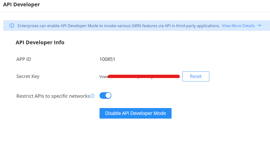
For further details, please refer to the GWN API Developer Guide
MANAGER SETTINGS
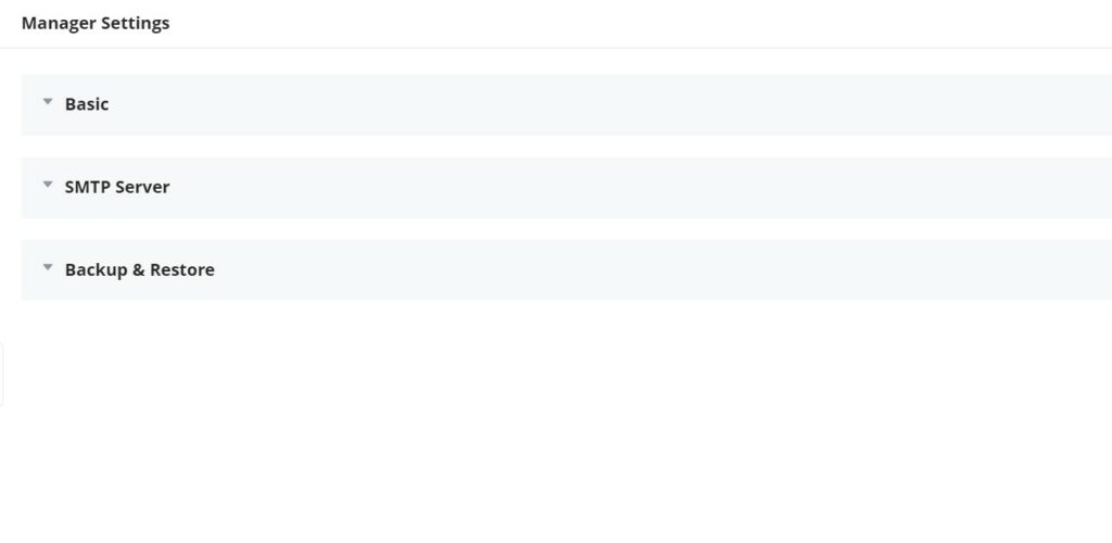
Basic
In this section, the user can download the Manager log files by clicking on the “Export” button as shown below, as well as enabling “Remote Assistance” in case the users need professional help from experts or support.
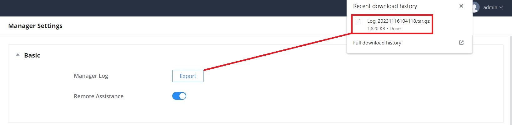
SMTP Server
To enable email notifications from GWN Manager, the user needs first to set up the SMTP Server here, once the SMTP Server configuration is set, please click on the “Send test email” button to test if it’s working or not.
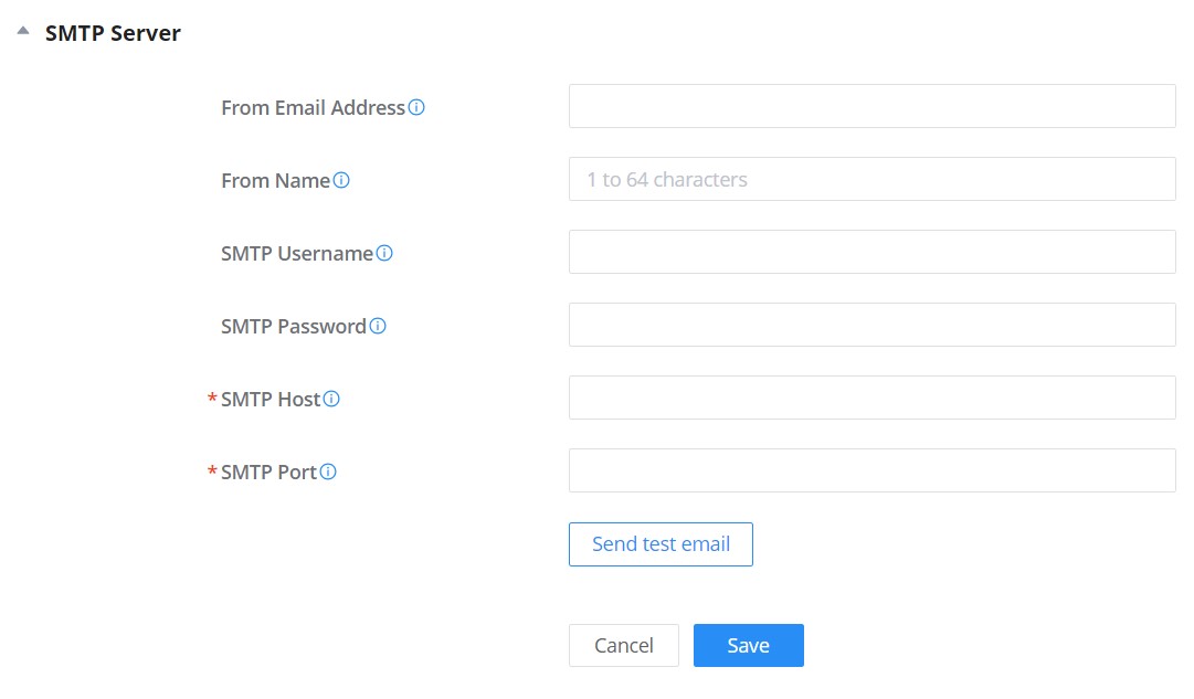
Backup & Restore
Users can Backup GWN Manager configuration as shown below:
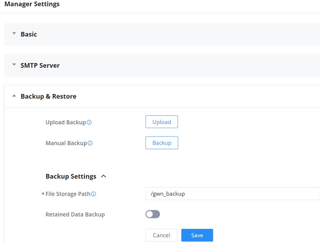
Users can click the “Upload” button to import a backup from the local directory. Or, click the “Backup” button to back up immediately.
REQUIREMENTS
The following tables show the requirements of Grandstream networking products including GWN Access Points, GWN Routers, GWN Switches, GCC Devices, and GWN App versions (Android® and iOS®) for GWN Management Platforms (GWN.Cloud & GWN Manager):
- GWN Access Points: minimum and recommended version
Model | Minimum | Recommended |
GCC6010 | 1.0.1.8 | 1.0.1.8 |
GCC6010W | 1.0.1.8 | 1.0.1.8 |
GWN7001 | 1.0.1.6 (1.0.5.35 for GWN Manager) | 1.0.5.35 |
GWN7002 | 1.0.1.6 (1.0.5.35 for GWN Manager) | 1.0.5.35 |
GWN7003 | 1.0.1.6 (1.0.5.35 for GWN Manager) | 1.0.5.35 |
GWN7052 | 1.0.5.34 (1.0.9.42 for GWN Manager) | 1.0.9.42 |
GWN7052F | 1.0.5.4 (1.0.9.42 for GWN Manager) | 1.0.9.42 |
GWN7062 | 1.0.5.34 (1.0.9.42 for GWN Manager) | 1.0.9.42 |
AP minimum and recommended version
- GWN Routers/GCC Devices: minimum and recommended version
Model | Minimum | Recommended |
GCC6010 | 1.0.1.8 | 1.0.1.8 |
GCC6010W | 1.0.1.8 | 1.0.1.8 |
GWN7001 | 1.0.1.6 (1.0.5.35 for GWN Manager) | 1.0.5.35 |
GWN7002 | 1.0.1.6 (1.0.5.35 for GWN Manager) | 1.0.5.35 |
GWN7003 | 1.0.1.6 (1.0.5.35 for GWN Manager) | 1.0.5.35 |
GWN7052 | 1.0.5.34 (1.0.9.42 for GWN Manager) | 1.0.9.42 |
GWN7052F | 1.0.5.4 (1.0.9.42 for GWN Manager) | 1.0.9.42 |
GWN7062 | 1.0.5.34 (1.0.9.42 for GWN Manager) | 1.0.9.42 |
GWN routers/GCC devices minimum and recommended version
- GWN Switches: minimum and recommended version
Model | Minimum | Recommended |
GWN7711 | 1.0.1.8 | 1.0.1.8 |
GWN7711P | 1.0.1.8 | 1.0.1.8 |
GWN7801 | 1.0.3.19 (1.0.5.52 for GWN Manager) | 1.0.5.52 |
GWN7801P | 1.0.3.19 (1.0.5.52 for GWN Manager) | 1.0.5.52 |
GWN7802 | 1.0.3.19 (1.0.5.52 for GWN Manager) | 1.0.5.52 |
GWN7802P | 1.0.3.19 (1.0.5.52 for GWN Manager) | 1.0.5.52 |
GWN7803 | 1.0.3.19 (1.0.5.52 for GWN Manager) | 1.0.5.52 |
GWN7803P | 1.0.3.19 (1.0.5.52 for GWN Manager) | 1.0.5.52 |
GWN7806 | 1.0.1.14 (1.0.5.52 for GWN Manager) | 1.0.5.52 |
GWN7806P | 1.0.1.14 (1.0.5.52 for GWN Manager) | 1.0.5.52 |
GWN7811 | 1.0.1.8 (1.0.7.64 for GWN Manager) | 1.0.7.64 |
GWN7811P | 1.0.1.8 (1.0.7.64 for GWN Manager) | 1.0.7.64 |
GWN7812P | 1.0.1.8 (1.0.7.64 for GWN Manager) | 1.0.7.64 |
GWN7813 | 1.0.1.8 (1.0.7.64 for GWN Manager) | 1.0.7.64 |
GWN7813P | 1.0.1.8 (1.0.7.64 for GWN Manager) | 1.0.7.64 |
GWN7816 | 1.0.3.8 (1.0.7.64 for GWN Manager) | 1.0.7.64 |
GWN7816P | 1.0.3.8 (1.0.7.64 for GWN Manager) | 1.0.7.64 |
GWN7830 | 1.0.3.3 (1.0.7.64 for GWN Manager | 1.0.7.64 |
GWN7831 | 1.0.3.3 (1.0.7.64 for GWN Manager) | 1.0.7.64 |
GWN7832 | 1.0.3.3 (1.0.7.64 for GWN Manager) | 1.0.7.64 |
Switch minimum and recommended version
- GWN App: minimum and recommended version
Platform | Minimum | Recommended |
iOS® | 1.0.5 | 1.6.7 |
Android® | 1.0.0.14 | 1.0.6.7 |
App minimum and recommended version
Requirements
To know more about the differences between Grandstream devices in terms of functions based on the recommended versions, please navigate to GWN.Cloud Web UI → About → Device Comparison. refer to the figures below:
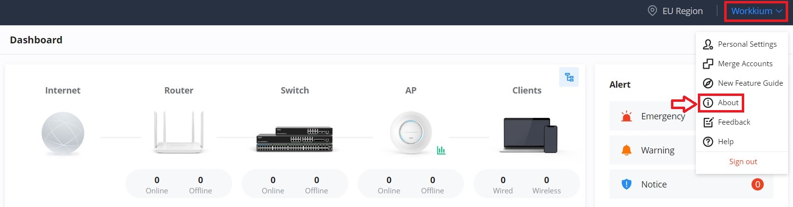
On this page, the users can find the minimum and recommended firmware version for each Grandstream device and APP (iOS® and Android®). If a Beta firmware is available for a device it will be also shown here.
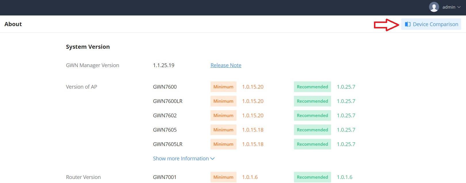
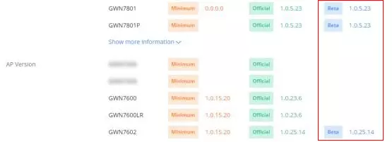
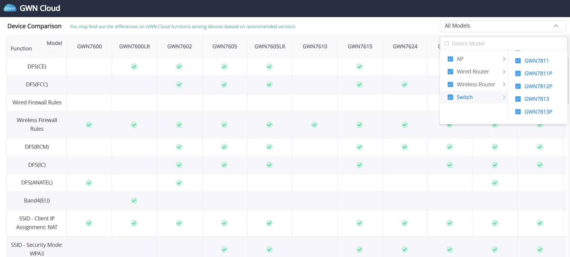
EXPERIENCING GWN MANAGEMENT PLATFORMS
Please visit our Website: http://www.grandstream.com to receive the most up-to-date updates on firmware releases, additional features, FAQs, documentation, and news on new products.
We encourage you to browse our product-related documentation, FAQs, and User and Developer Forum for answers to your general questions. If you have purchased our products through a Grandstream Certified Partner or Reseller, please contact them directly for immediate support.
Our technical support staff is trained and ready to answer all your questions. Contact a technical support member or submit a trouble ticket online to receive in-depth support.
Thank you again for using Grandstream GWN Management Platforms, it will be sure to bring convenience to both your business and personal life.
CHANGE LOG
This section documents significant changes from previous versions of the GWN Management Platform User Manuals. Only major new features or major document updates are listed here. Minor updates for corrections or editing are not documented here.
Version 1.1.28.27
Product Name: GWN Manager
- Added security enhancement by verifying device password when adding a switch or a router. [Adopt a Device to GWN Manager]
Version 1.1.28.25
Product Name: GWN.Cloud and GWN Manager
- Added support of GCC601X SMB UC/Networking Convergence Solutions [Requirements]
- Added the ability to update AP info in real time when enter AP detailed page [GWN AP Info]
- Added the ability to customize MAC for client isolation in wireless LAN [Add SSID]
- Added a new feature of OS Filter in wireless LAN [Add SSID]
Version 1.1.28.9 – 1.1.28.10
Product Name: GWN.Cloud(1.1.28.9) and GWN Manager(1.1.28.10)
- Supports link speed display for APs on the device list. [Devices]
- Supports L2TPv3 configuration on GWN7660 series APs (supported only GWN.Cloud) [GWN AP L2TPv3]
- Supports cloning the LAN and wired firewall configuration [Create a new network]
- Added Beta firmware display and supports upgrading to Beta. [Requirements]
- Optimized client list sorting. [Clients]
- Supports local WAN configuration synchronization. [Add device to GWN.Cloud]
- Optimized Feedback entry. [Feedback]
- Added PPSK configuration, inventory information acquiring, and switch port information acquiring for API. [API Developer]
- Added GWN Manager Upgrade support [Manager Upgrade]
Version 1.1.27.13
Product Name: GWN.Cloud and GWN Manager
- Added Regions/Systems Switch to allow multiple regions/systems to be opened. [Region settings]
- Upgraded Account Permission, allowing comprehensive management of all Grandstream services and enable all systems in the selected region. [Merge Accounts]
- Added Associated Company to support cross-region/cross-system management on channels and customers for network sharing and device allocation. [Associated Company]
- Added Reseller Channel to support the establishment of hierarchy in agent partnership, obtain device from ERP, and assign device to network groups or channels/agents. [Reseller Channel]
- Optimized User Management, unified management of account and password security. [account security settings]
- Optimized Personal Settings page and added user type settings. [Personal Settings]
- Added API support for exporting the switch information, mainly the information and port modules in the switch details, and the information of the global switch settings. [API]
- Added API support for PPSK configuration. [API]
Version 1.1.26.11
Product Name: GWN.Cloud and GWN Manager
- Added Pre-Provisioning for Switch in device management for port Setting, port profile, and DHCP Snooping. [Switch Pre-Provisioning]
- Added remarks and serial number fields for device export. [Devices]
- Added more default Wall Types and optimized attenuation values for Floor Plans. [Floor Plans]
- Added support for topology export. [Network Topology]
- Added MAC search field in Upgrade History. [Upgrade History]
- Added a column to display the network that the device was returned from. [Inventory]
- Added support for custom role users to log in to GWN APP. [User Management]
- Increased Password Security, added password expiration and conflict limits configuration. [Personal Settings]
- Added support hiding Weak Heat Map signal. [Floor Plans]
- Removed SMTP Username/Password requirement. [SMTP Server]
Version 1.1.25.23
Product Name: GWN.Cloud and GWN Manager
- Added features of multiple VPN tunneling methods such as PPTP, IPSec, OpenVPN®, and WireGuard®, and IPSec supports automatic networking mode. [VPN]
- Added the feature of managing multiple routers at the same time on the same network. [Devices]
- Added device group management, and pre-set features for switches in the group. And a new way to select device groups in multiple businesses. [Group management]
- Added the feature of pushing cloud configuration to the local side of the device, and the push method includes manual and automatic. [Devices]
- Added a new feature for network speed test of APs. [configure a GWN Access Point]
- Added a new feature for 12-hour network health monitoring of WAN ports. [WAN]
- Added a new feature of policy routes. [Policy routes]
- Added a new feature of certificate management. [Certificate]
- Added floor plan management features, support device RF heat map preview, and convenient device placement planning. [Floor plans]
- Added the feature of Cloud DDNS service. [WAN]
- Added a new feature of VLAN interface configuration for routers. [Configure a GWN Router]
- Added alerts such as abnormal device time, abnormal temperature of the optical module, and VPN-related alerts [Alerts]
- Supports automatic time synchronization between routers and switches with cloud [System]
- Supports IPv6 PD/prefix length configuration in WAN [WAN]
- Added the ability to set the Primary Network for cloud [Network Overview]
- Added the ability to retrieve Guest information with API commands.
- Added the ability to display the Wi-Fi version used in the client’s information [Clients]
- Added the ability to Customize the Channel in the 2.4G band [Wi-Fi]
- Added the ability to disable the Router LAN ports [Configure a GWN router]
- Added the ability to configure the router/switch device password from GWN Cloud [Configure a device]
- Added the ability to support batch or single configuration for the Device Password [System]
- Added the ability to highlight mesh devices in Network Topology [Topology]
- Added the ability to configure Port Profile for Device Group [Port profile]
- Added the ability to display the router’s LAN IP address [Devices]
- Added a new feature of VLAN Interface configuration for routers [Configure a GWN router]
- Added API support for Device Name and Equipment Remarks.
Version 1.1.24.28
Product Name: GWN.Cloud and GWN Manager
- Adjust the upper limit to 300 on the number of PPSK in a group [PPSK]
- Support to display the switch port info on the client list when the client connects to the switch [Clients]
- Support the option “Timeout Duration of Unauthenticated Clients” on the external splash page [Portal Policy]
- Support the option “URL Pre-shared Key” when selecting Aiwifi as the platform of the external splash page [Portal Policy]
Version 1.1.24.23
Product Name: GWN.Cloud and GWN Manager
- Added the unified management for model of GWN7801(P),GWN7802(P),GWN7803(P)
- Added the support for Device Information, Configuration, and Debug under the Device menu for GWN switch models [Configure a GWN Switch]
- Added the support for GWN switches & port configurations through Global Switch Settings and Port Profiles [DEVICES]
- Added the support for GWN switches in Topology (including wired devices hierarchy relationship) [Network Topology]
- Added the support of GWN switches’ Alert events [ALERTS]
- Added a new feature of user role management and customizable role privilege [USER MANAGEMENT]
- Added a new feature of Organization Overview [ORGANIZATION]
- Added a new feature of Map for device location management [Map]
- Added a new feature of AP batch configuration [Configuration]
- Added a new feature of displaying Change logs’ content details [Organization Change Log]
- Added a new feature of transferring management permission for shared Network [Share a Network]
- Added a new feature of restricting APIs to specific networks [API Developer]
- Added a new feature of batch firmware upgrade for different GWN models to the recommended version [Upgrade]
- Added a new feature of disabling AP’s Ports [Configuration]
- Added a new feature of Limit by Authentication Type for Daily Limit of Captive Portal [Profiles]
- Added a new feature of Active Directory into Splash Page Logging Components [Splash Page]
- Added a new feature of grouping top website statistics by Main Domain rather than URL
- Added a new feature of PPSK With Radius into SSID Security Type [Wireless LAN]
Version 1.1.23.27
Product Name: GWN.Cloud and GWN Manager
- New Cloud Web Portal, SDN concept & UI design
- Unified GWN device management (Access points, Routers, Switches) [Devices]
- Inventory management [Inventory]
- New Network topology (replacing the old mesh topology) [Network Topology]
- New Alert design and support more alert events [Alerts]
Version 1.0.22.23
Product Name: GWN Manager
- Added feature of U-APSD for AP [SSID]
- Added feature of Email authentication for Captive Portal [Splash page]
- Added feature of post-authentication rules for Captive Portal [Portal Policy]
- Added feature of service auto start after machine reboot for GWN Manager
Version 1.0.21.17
Product Name: GWN Manager
- Added feature of reporting Probe request RSSI information
- Added feature to export APs, clients, and alerts [Devices] [Clients]
- Added feature of Google Authentication [Splash page]
- Added feature of WiFi4EU [Splash page]
- Added feature of SMS authentication for Captive Portal [Splash page]
- Added feature of Hotspot 2.0 R3 [Hotspot 2.0]
- Added support to transfer APs to GWN Manager
Version 1.0.19.8
Product Name: GWN Manager
- No major changes.
Version 1.0.19.7
Product Name: GWN Manager
- Added support for deleting the voucher in use. [Voucher]
- Added support of client name in CSV file when importing access list. [Access List]
- Added configuration of secondary radius server for WLAN 802.1x authentication. [Wi-Fi Settings]
- Added WPA3 support in the SSID setting. [Wi-Fi Settings]
- Added NET Port Type option for AP setting
Version 1.0.19.2
Product Name: GWN Manager
- Added support of Top Website statistic graph [Overview]
- Added support of Guest Count statistic graph [Captive Portal Summary]
- Added manager role: Network Administrator [USER MANAGEMENT]
- Added support of API Developer [API Developer]
- Added support of Access List Import in CSV [Access List]
- Added support of Rogue AP Detection [Rogue AP]
- Added support of SNMP [SNMP]
- Added support of Allow DHCP Option 43 to override GWN Manager Address [Discover GWN76xx]
- Added support of NAT [NAT Pool]
- Added support of Firewall [Firewall]
- Added support of Hotspot 2.0 Beta [Hotspot 2.0]
Version 1.0.10.7
Product Name: GWN.Cloud
- Added Site Survey feature [Site Survey]
- Added feature of Minimum Rate Control. [Enable Minimum Rate]
- Added feature of SSH Remote Access. [SSH Remote Access]
- Added feature of External Portal support Socifi Platform.
- Added feature of Client inactivity timeout. [Client Inactivity Timeout]
- Added feature of Upgrade Regularly [Upgrade]
- Added feature of Client Steering [Client Steering]
- Enhanced feature of Voucher: the display of remaining bytes. [Voucher]
- Enhanced feature of Dynamic VLAN
- Changed LED patterns [GWN76xx LED Patterns]
Version 1.0.9.8
Product Name: GWN.Cloud
- Added support for collecting user feedback from the GWN Cloud page. [Feedback]
- Added support for Voucher Style Customization. [Voucher]
- Added support for video URL. [Advertisement]
- Added support to export Guest Information via Email. [Email Guest Information]
- Added support for client RX/TX Rate display. [Dashboard]
- Expanded Max Devices to use the same Voucher. [Voucher]
- Added support to enable/disable client connection/disconnection events.
Version 1.0.8.17
Product Name: GWN.Cloud
- Added support for Advertisement for Captive Portal [Advertisement]
- Added support for Custom Field for Captive Portal Splash Page [Splash Page]
- Added feature of ARP Proxy. [ARP Proxy]
- Added support of Clear client data. [Clients]
- Enhanced Event log by Wi-Fi authentication event. [Event Log per AP]
- Added EU Server support. [Zone]
- Enhanced Bandwidth Rules by adding an option to limit bandwidth per client. [Range Constraint]
- Added Total Bandwidth Usage Display [Dashboard]
- Added Export Immediately feature for URL Access Logs. [URL Access Log]
Version 1.0.8.7
Product Name: GWN.Cloud
- Added support for URL logging (Except for GWN7610). [URL Access Log]
Version 1.0.7.18
Product Name: GWN.Cloud
- Enhanced Client Information. [Dashboard]
- Enhanced Access Point status. [Info]
- Added Reset access point button. [Reset Device]
- Added External Captive Portal Support. [External Splash Page]
- Added AP Scheduling Reboot. [Reboot Schedule]
- Added Change Log section. [Change Log]
- Added Account idle timeout. [Account Idle timeout]
- Added feature of Wi-Fi Statistic Report. [Report]
- Added feature of Captive Portal Guest Summary. [Guests]
- Changed SSID limit. [SSID]
- Enhanced Wi-Fi Service by adding configurable options. [Wi-Fi]
- Enhanced Captive Portal features. [Failsafe Mode] [Daily Limit] [Byte Quota] [Force To Follow] [Portal Policy]
Version 1.0.0.37
Product Name: GWN.Cloud
- This is the initial version for GWN.Cloud.
Version 1.0.0.33
Product Name: GWN Manager
- This is the initial version for GWN Manager.
Android is a trademark of Google LLC.
iOS is a trademark or registered trademark of Cisco in the U.S. and other countries and is used under license by Apple Inc.
Linux® is the registered trademark of Linus Torvalds in the U.S. and other countries.
macOS® is a trademark of Apple Inc., registered in the U.S. and other countries.
Windows® is a trademark of Microsoft Corporation in the United States and other countries.