In this guide, we will present the configuration parameters of the GCC601x(W) Network nodes module.
OVERVIEW
In the context of network management, network nodes refer to individual devices or components, such as switches and access points, that form the interconnected infrastructure being monitored. These nodes provide data points for analysis, helping the monitoring platform to assess the health, performance, and security of the overall network.
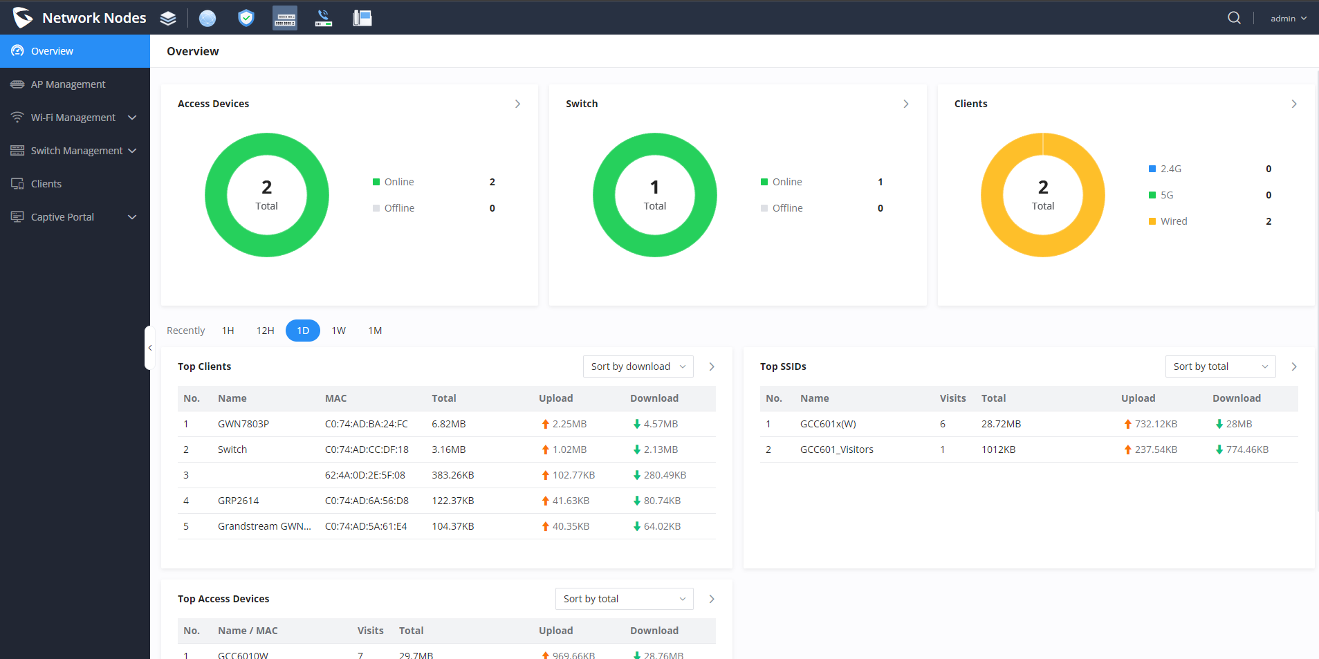
After successful login to the GCC601X(W)’s Network Nodes Web Interface, the overview web page will provide an overall view of the GCC601X(W)’s information presented in a Dashboard style for easy monitoring. Please refer to the figure and table below:
Overview
Access Devices
Shows the total number of Access Devices online and offline.
Switch
Displays the list of switches paired with the GCC, and shows a status of both online and offline devices.
Clients
Shows the total number of clients connected either wirelessly (2.4G and 5G) and also wired connections.
Top Clients
Shows the Top Clients list, users may assort the list of clients by their upload or download. Users may click on to go to Clients page for more options. You have the possibility to sort the connected clients by :
Upload: Displays the total download rate used by the device
Download: Displays the total upload rate used by the device
Users can also specify the time span of the data being displayed, either 1 hour, 12 hours, 1 day, 1 week, or 1 month
Top SSIDs
Shows the Top SSIDs list, users may assort the list by number of clients connected to each SSID or data usage combining upload and download. Users may click on to go to SSID page for more options. You have the possibility to sort the connected clients by : Total connected devices, or by the number of visits
Top Access Devices
Shows the Top Access Devices list, assort the list by the number of clients connected to each access device or data usage combining upload and download. Click on the arrow to go to the access point page for basic and advanced configuration options.
Overview page
AP MANAGEMENT
The user can add the access point, which can be controlled using the embedded controller within the GCC601X(W) device. The user can either pair with or take over an access point to be able to configure it. The configuration performed on the GCC601X(W) AP embedded controller will be pushed to the access points, thus offering centralized management of the GWN access points.
Add a new Access Point
Note
GCC601xW wireless models will have an embedded default AP with the name of the device itself, as opposed to the wired models (GCC601x), which will not have any embedded AP.
The GWN76XX AP firmware version 1.0.25.30 and above supports official online updates and management by the GCC device.
Wi-Fi 7 capable access points are supported. When configuring such devices, additional Wi-Fi 7 specific options appear under the SSID settings.
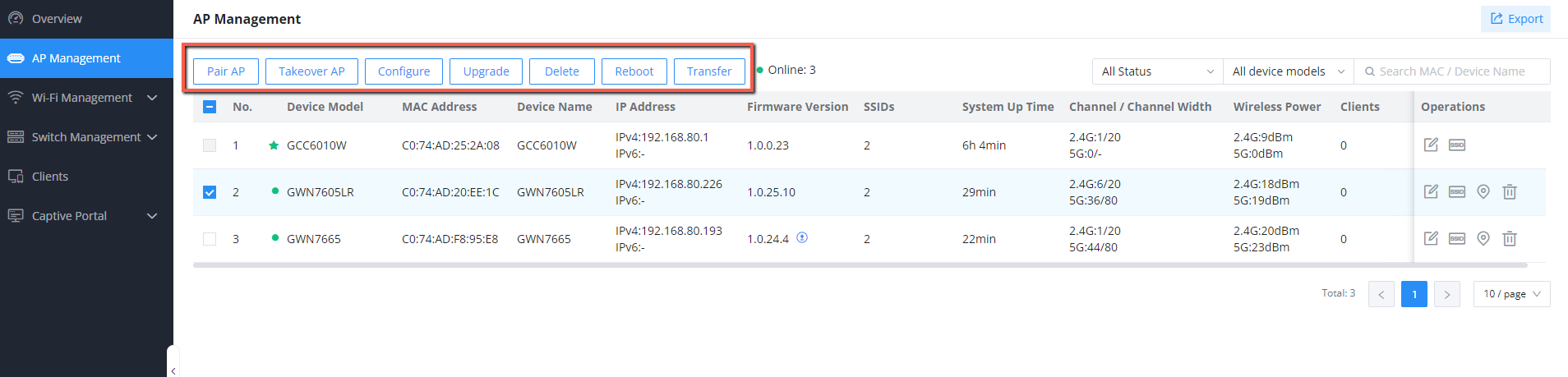
To add a GWN access point to the GCC601X(W), please navigate to Web UI → AP Management
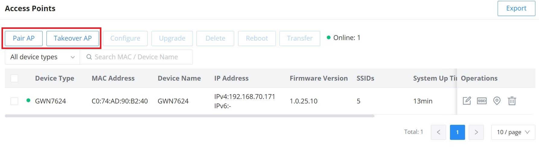
Access Points List
Pair AP: Use this button when pairing an AP that has not been set as a master. Takeover AP: Use this button to take over an access point that has formerly been set as a slave to a different master device. To pair the devices successfully, the network administrator must enter the password of the master device.
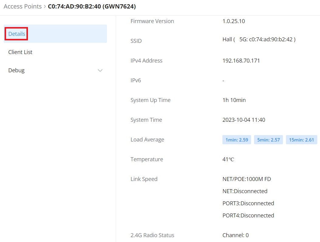
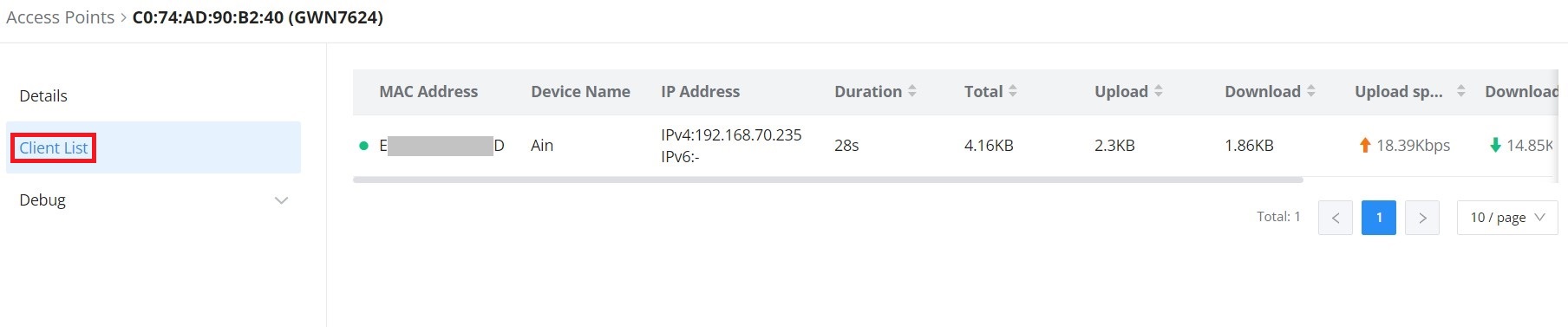
Click on a paired GWN AP to view Details, Client list, and debug tools. Please refer to the figures below:
The Details section contains details about the paired AP, like firmware version, SSID, IP address, Temperature, etc.
Paired APs Details
The Client List section lists all the connected clients through this AP with much info like MAC Address, Device name, IP Address, bandwidth, etc.
Paired APs Client list
After the access point has been added, the user can select it and perform one of the following actions:
The configuration page allows the administrator to upgrade, reboot, add to SSIDs, Configure, Transfer network group, Transfer AP, Discover AP, and Failover.
GCC601xW Configuration Page
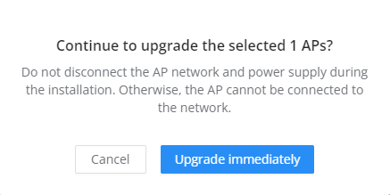
Upgrade the AP
Select a slave AP(s) to upgrade and press the button.
Reboot Slave AP
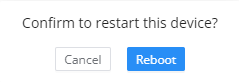
To reboot a slave AP, select it, then click on button. The below confirmation message will be displayed:
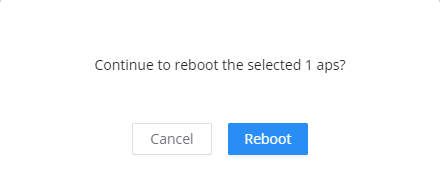
Reboot Access Point
Delete Access Points
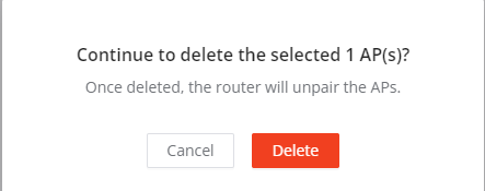
To delete an access point, select it, then click on the delete button. The following confirmation message will be displayed:
Delete Access Point
Configure Access Points
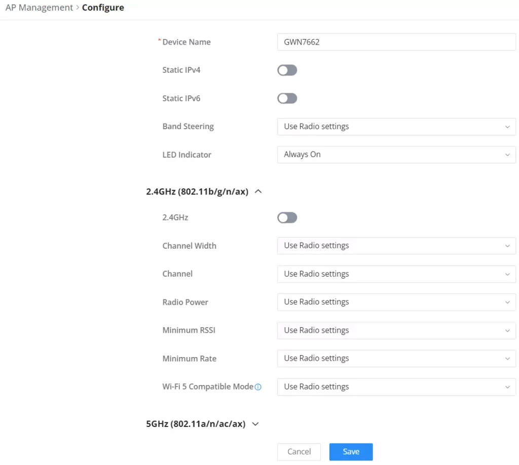
To configure an access point, select and click on the button. A new config page will pop up:
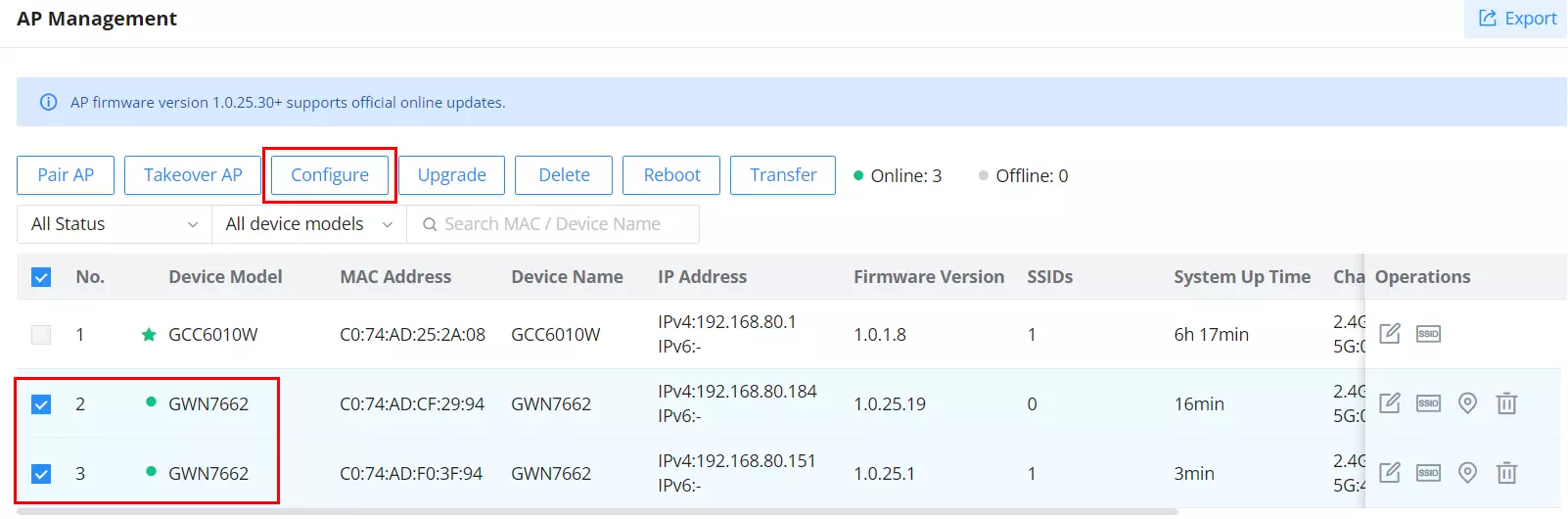
Configure AP
Device Name
Set GWN76xx’s name to identify it along with its MAC address.
Static IPv4
Check this option to configure the device with a static IP configuration; it must be in the same subnet with the default Network Group; Once enabled, these fields will show up: IPv4 Address/IPv4 Subnet Mask/IPv4 Gateway/Preferred IPv4 DNS/Alternate IPv4 DNS.
Static IPv6
Check this option to configure the device with a static IP configuration; it must be in the same subnet with the default Network Group; Once enabled, these fields will show up: IPv6 Address/IPv6 Prefix Length/IPv6 Gateway/Preferred IPv6 DNS/Alternate IPv6 DNS.
Band Steering
Band Steering will help redirect clients to a radio band 2.4G or 5G, depending on what is supported by the device, to increase efficiency and benefit from the maximum throughput.
Four options are allowed by GDMS:
Disable Band steering: This will disable the band steering feature and the access point will accept the band chosen by the client.
2G in Priority: 2G Band will be prioritized over 5G Band.
5G in Priority: 5G Band will be prioritized over 2G Band
Balance: Band Steering will balance between the clients connected to 2G and 5G.
Use Radio Settings: GWN will use the value configured under Radio page.
LED indicator
Configure the LED: Four options are available: Use System Settings, Always on, Always off, or Schedule.
2.4G/5G (802.11b/g/n/ax)
Disable 2.4GHz/5GHz
This feature allows the user to disable/enable its 2.4GHz/5GHz band on the AP.
Channel Width
Choose the Channel Width, note that wide channels will give better speed/throughput, and narrow channel will have less interference. 20Mhz is suggested in a very high-density environment. Default is “Use Radio Settings”, the AP then will use the value configured under the Radio page.
Channel
Select Use Radio Settings, or a specified channel, default is Auto. Note that the proposed channels depend on Country Settings under System Settings → Maintenance. Default is “Use Radio Settings”, the AP then will use the value configured under Radio page.
Radio Power
Set the Radio Power depending on the desired cell size to be broadcasted, five options are available: “Low”, “Medium”, “High”, “Custom” and “Use Radio Settings”.
The default is “Use Radio Settings”, the AP then will use the value configured under the Radio page
Minimum RSSI
Configure whether to enable/disable Minimum RSSI function. This option can be either Disabled or Enabled and set manually or set to Use Radio Settings.
Minimum Rate
Specify whether to limit the minimum access rate for clients. This function may guarantee the connection quality between clients and APs. This option can be either Disabled or Enabled and set manually or set to Use Radio Settings.
Wi-Fi 5 Compatible Mode
Some old devices do not support Wi-Fi 6 well, and may not be able to scan the signal or connect poorly. After enabled, it will switch to Wi-Fi 5 mode to solve the compatibility problem. At the same time, it will turn off Wi-Fi 6 related functions.
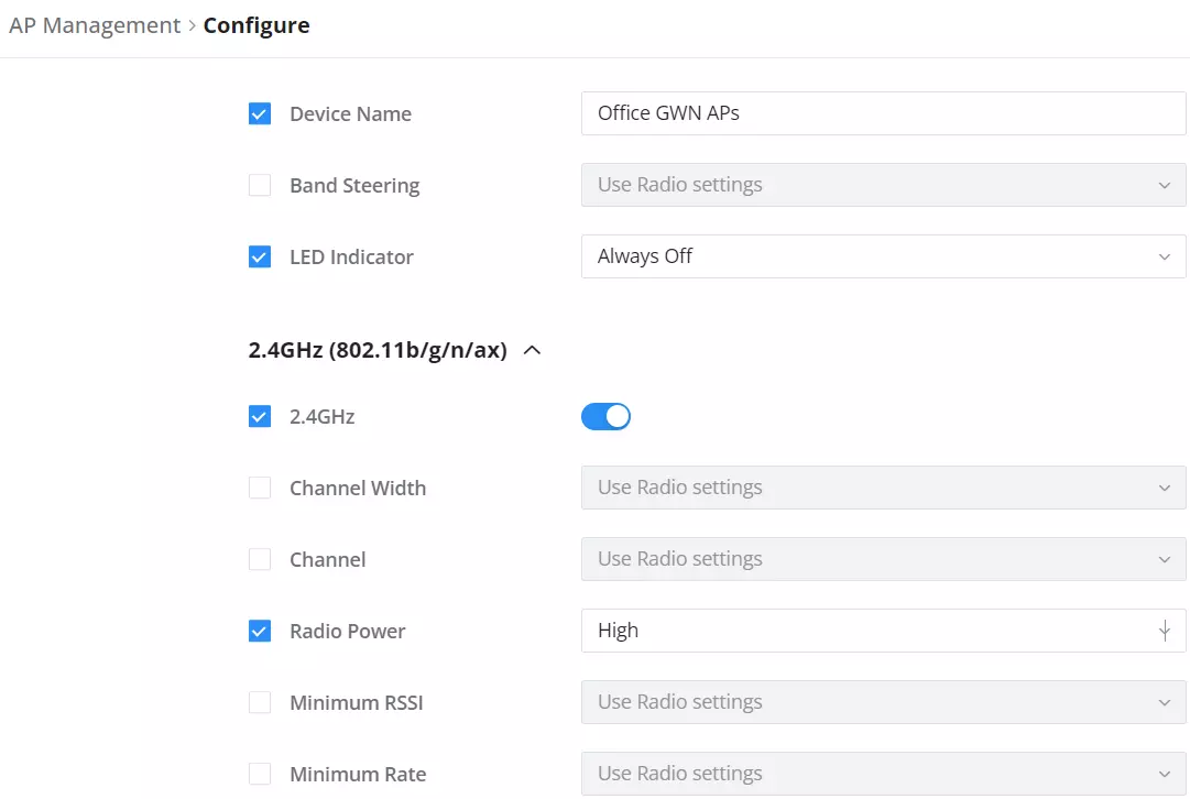
Batch Configuration of APs
Batch configuration for Access Points (APs) significantly enhances efficiency and consistency by allowing simultaneous configuration of multiple devices. This approach reduces setup time, ensures uniform settings across all APs, minimizes human error, and improves overall network reliability and security. It streamlines network management, making deployment and maintenance more efficient and scalable.
Batch configuration of APs
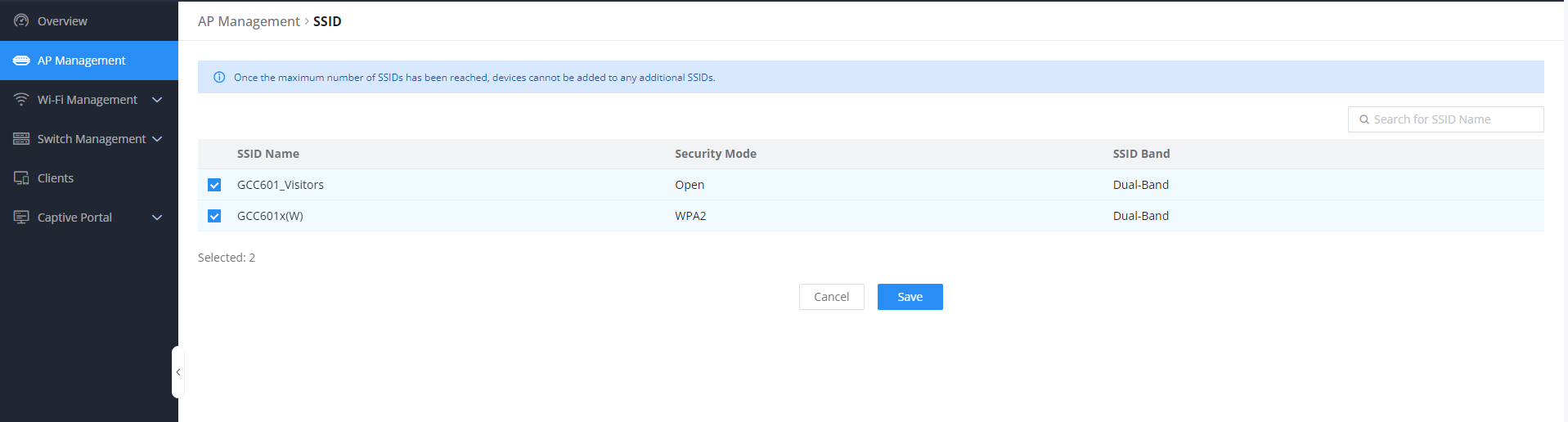
Assign SSIDs to AP
By clicking the icon it will display the configuration page responsible for assigning the created SSIDs to the selected AP
Note
Once the maximum number of SSIDs has been reached, devices cannot be added to any additional SSIDs.
Locate AP
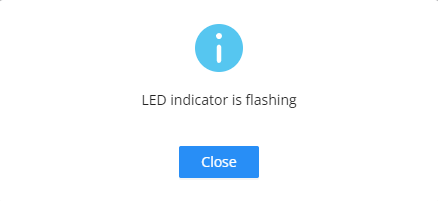
By clicking the icon , you allow the GCC610x(W) to send an LED notification to the connected AP to locate it
Transfer APs to GDMS
GWN routers also enable users to transfer their paired GWN APs to GDMS.
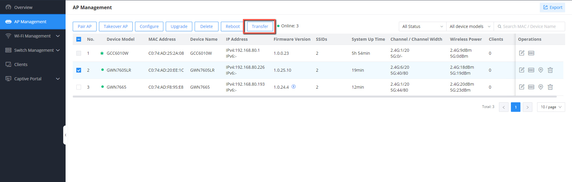
On the AP Management → Access Points page, select the AP or APs, then click on the “Transfer” button as shown below:
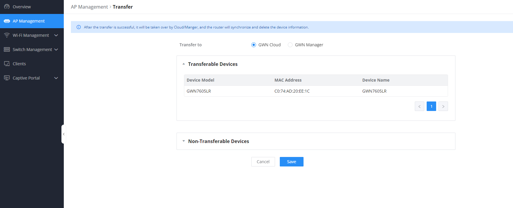
On the next page, select either GDMS (Cloud or Local), then click the “Save” button. The user will be forwarded automatically to either GDMS (Cloud or Local) to log in.
Transfer AP to GDMS
Note:
After successful transfer, it will be taken over by Cloud/Manager, and the GCC601x(W) will delete the device information synchronously.
WIFI MANAGEMENT
SSIDs
On this page, the user can configure SSID settings. The Wi-Fi SSID will be broadcast by the paired access points. This offers centralized control over the SSIDs created, which makes managing many GWN access points easier and more convenient.
SSID page
To add an SSID, the user should click on the “Add” button, and then the following page will appear:
Add SSID
Basic Information
Wi-Fi
Toggle on/off the Wi-Fi SSID.
Name
Enter the name of the SSID.
Associated VLAN
Toggle “ON” to enable VLAN, then specify the VLAN from the list or click on “Add VLAN” to add one.
SSID Band
Choose the Wi-Fi SSID band.
2.4G: Only 2.4G band is enabled.
5G: Only 5G band is enabled.
6G: Only 6G band is enabled.
Note: 6G band is only effective for AP devices that support Tri-Band.
MLO
When MLO (Multi-Link Operation) is enabled, compatible client devices can form simultaneous connections across multiple frequency bands (2.4 GHz, 5 GHz, and 6 GHz) using a single SSID. This can significantly increase throughput, reduce latency, and enhance roaming stability.
Notes:
This setting applies only to Wi-Fi 7 capable access points
Enabling MLO will restrict the available WPA Encryption Type options for security.
Access Security
Security Mode
Choose the security mode for the Wi-Fi SSID.
Open
WPA/WPA2
WPA2
WPA2/WPA3
WPA3
WPA3-192
WPA Key Mode
Depending on the security mode chosen, the WPA Key mode will be different, the following options are available for each corresponding security mode.
Open : It will not have any WPA Key Mode
WPA/WPA2: It will have PSK and 802.1x WPA key modes
WPA2: It will have PSK, 802.1x, PPSK without Radius, and PPSK with RADIUS
WPA2/WPA3: It will have SAE-PSK, and 802.1x
WPA3: SAE, and 802.1x are supported
WPA3-192: 802.1x is supported
WPA Encryption Type
Choose the encryption type:
AES
AES/TKIP
Note: Enabling MLO disables certain legacy encryption types (such as AES/TKIP) to ensure a consistent and secure connection across all radio links.
WPA Shared Key
Enter the shared key phrase. This key phrase will be required to enter when connecting to the Wi-Fi SSID.
Enable Captive Portal
Toggle Captive Portal on/off.
Captive Portal Policy: Choose the created captive portal policy.
Blocklist Filtering
Choose a blocklist for the Wi-Fi SSID, Please refer to the [blocklist] configuration
Client Isolation
Closed: Allow access between wireless clients.
Radio: All wireless clients will be isolated from each other.
Internet: Access to any private IP address will be blocked.
Gateway MAC: Private IP addresses except for the configured gateway will be blocked.
802.11w
This setting enhances security by protecting unicast and multicast management frames. The options are:
Disable: No protection for management frames.
Optional: Protected frames are used if both the AP and client support it (capable clients will use protection)
Required: The AP will only allow connections from clients that support management frame protection
Advanced
SSID Hidden
After enabled, wireless devices will not be able to scan this Wi-Fi, and can only connect by manually adding network.
DTIM Period
Configure the delivery traffic indication message (DTIM) period in beacons. Clients will check the device for buffered data at every configured DTIM Period. You may set a high value for power saving consideration. Please input an integer between 1 to 10.
Wireless Client Limit
Configure the limit for wireless client, valid from 1 to 256. If every Radio has an independent SSID, each SSID will have the same limit. Therefore, setting a limit of 256 will limit each SSID to 256 clients independently.
Client Inactivity Timeout (sec)
Router/AP will remove the client’s entry if the client generates no traffic at all for the specified time period. The client inactivity timeout is set to 300 seconds by default.
Multicast Broadcast Suppression
Disabled: all of the broadcast and multicast packages will be forwarded to the wireless interface.
Enabled: all of the broadcast and multicast packages will be discarded except DHCP/ARP/IGMP/ND.
Enabled with ARP Proxy: enable the optimization with ARP Proxy enabled in the meantime.
Convert IP Multicast to Unicast
Disabled: No IP multicast packets will be converted to unicast packets.
Passive: The device will not actively send IGMP queries, and the IGMP snooping entries may be aged after 300s and cannot be forwarded as multicast data.
Active: The device will actively send IGMP queries and keep IGMP snooping entries updated.
Schedule
Enable then select from the drop-down list or create a time schedule when this SSID can be used.
802.11r
Enables fast roaming for mobile devices within a Wi-Fi network, reducing connection dropout during transitions between access points by enabling pre-authentication and key caching.
802.11k
Enables devices to optimize their Wi-Fi connections by providing information about nearby access points, assisting in seamless roaming and network efficiency improvements.
802.11v
Enhances network management by enabling capabilities such as radio resource measurement and assisted roaming, improving overall network performance and client experience within a Wi-Fi environment.
ARP Proxy
Once enabled, devices will avoid transferring the ARP messages to stations, while initiatively answer the ARP requests in the LAN.
U-APSD
Configures whether to enable U-APSD (Unscheduled Automatic Power Save Delivery).
Bandwidth Limit
Toggle ON/OFF Bandwidth limit
Note: If Hardware acceleration is enabled, Bandwidth Limit does not take effect. Please go to Network Settings/Network Acceleration to disable
Maximum Upload Bandwidth
Limit the upload bandwidth used by this SSID. The range is 1~2560 Mbps. If the field is empty, there is no limit
The values can be set as Kbps or Mbps.
Maximum Download Bandwidth
Limit the download bandwidth used by this SSID. The range is 1~2560 Mbps. If the field is empty, there is no limit
The values can be set as Kbps or Mbps.
Bandwidth Schedule
Toggle ON/OFF Bandwidth Schedule; if it’s ON, then select a schedule from the drop-down list or click on “Create Schedule“.
Device Management
In this section, the user is able to add and remove the GWN access points that can broadcast the Wi-Fi SSID. There is also the option to search the device by MAC address or name.
Add SSID
Note
Only GCC6010W will have a default SSID of the embedded AP
Private Pre-Shared Key (PPSK)
PPSK (Private Pre-Shared Key) is a way of creating Wi-Fi passwords per group of clients instead of using one single password for all clients. When configuring PPSK, the user can specify the Wi-Fi password, maximum number of access clients, and maximum upload and download bandwidth.
Note
PPSKs can be delivered and managed directly through the GDMS networking cloud account, considering the GCC device is connected and added to the cloud.
To start using PPSK, please follow the steps below:
First, create an SSID with WPA key mode set to either PPSK without RADIUS or PPSK with RADIUS.
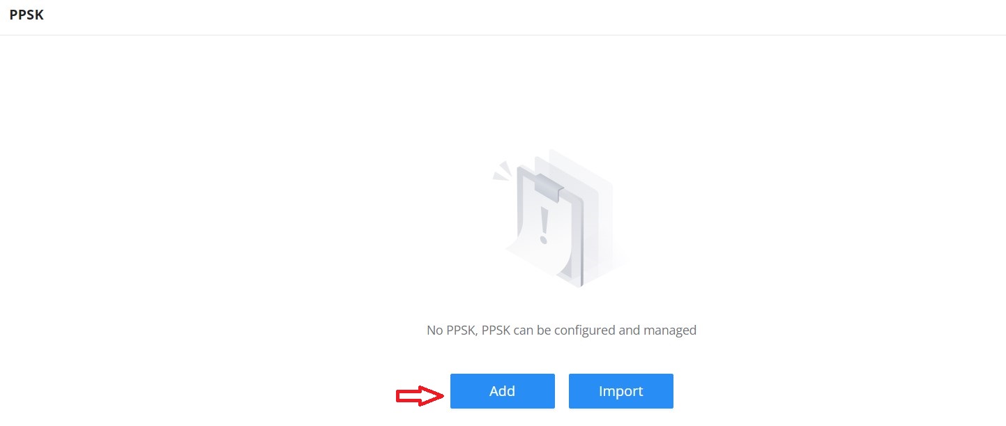
Navigate to Web UI → AP Management → PPSK page, then click on the “Add” button, then fill in the fields as shown below:
PPSK page
Add PPSK
SSID Name
Select from the drop-down list the SSID that has been previously configured with WPA Key mode set to PPSK without RADIUS or PPSK with RADIUS.
Account
If the WPA key mode in the selected SSID is “PPSK with RADIUS”, the account is the user account of the RADIUS server.
Wi-Fi Password
Specify a Wi-Fi password
Maximum Number of Access Clients
Confgures the maximum number of devices allowed to be online for the same PPSK account.
MAC Address
Enter a MAC Address
Note: this field is only available if the Maximum Number of Access Clients is set to 1.
Maximum Upload Bandwidth
Specify the maximum upload bandwidth in Mbps or Kbps.
Maximum Download Bandwidth
Specify the maximum downlolad bandwidth in Mbps or Kbps.
VLAN ID
Specify the VLAN ID to assign to the PPSK entry. This allows traffic from clients using the PPSK to be tagged with a specific VLAN. Range: 2–4093 (excluding 666).
Description
Specify a description for the PPSK
Add PPSK
Radio
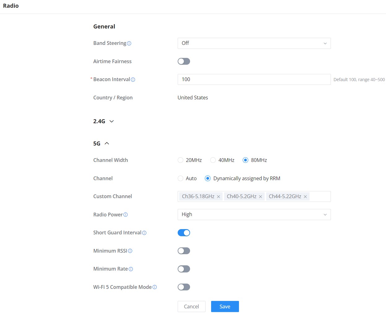
Under Wi-Fi Management → Radio, the user will be able to set the general wireless settings for all the Wi-Fi SSIDs created by the router. These settings will take effect on the level of the access points that are paired with the router.
Radio
General
Band Steering
Band steering functions are divided into four items: 1) 2.4G in priority, lead the dual client to the 2.4G band; 2) 5G in priority, the dual client will be led to the 5G band with more abundant spectrum resources as far as possible; 3) Balance,access to the balance between these 2 bands according to the spectrum utilization rate of 2.4G and 5G. In order to better use this function, proposed to enable voice enterprise via SSIDs → Advanced → Enable Voice Enterprise.
Airtime Fairness
Enabling Airtime Fairness will make the transmission between the access point and the clients more efficient. This is achieved by offering equal airtime to all the devices connected to the access point.
Beacon Interval
Configures the beacon period, which decides the frequency the 802.11 beacon management frames router transmits. Please input an integer, from 40 to 500.1. When router enables several SSIDs with different interval values, the max value will take effect;2. When router enables less than 3 SSIDs, the interval value will be effective are the values from 40 to 500;3. When router enables more than 2 but less than 9 SSIDs, the interval value will be effective are the values from 100 to 500;4. When router enables more than 8 SSIDs, the interval value will be effective are the values from 200 to 500.Note: mesh feature will take up a share when it is enabled.
Country / Region
This option shows the country/region which has been selected. To edit the region, please navigate to System Settings → Basic Settings.
2.4G & 5G & 6G
Channel Width
Select the channel width.
2.4G: 20Mhz, 20&40Mhz, 40Mhz
5G: 20Mhz, 40Mhz, 80Mhz
6G: 20Mhz, 40Mhz, 80Mhz, 160Mhz
Channel
Pick how the access points will be able to choose a specific channel.
Auto: The access point automatically selects the best available channel based on its own analysis.
Dynamically assigned by RRM: The channel is chosen and managed dynamically by a centralized Radio Resource Management (RRM) system for optimal network performance.
Custom Channel
Select a custom channel(s) from the drop-down list.
2.4G: Channel from 1 to 11.
5G: there are 2 categories, General channel and DFS channel.
Radio Power
Please select the radio power according to the actual situation, too high radio power will increase the disturbance between devices.
Low
Medium
High
Custom
Dynamically Assigned by RRM
Auto
Short Guard Interval
This can improve the wireless connection rate if enabled under non multipath environment.
Allow Legacy Devices (802.11b)
Controls whether the access point allows devices using the older 802.11b Wi-Fi standard to connect. this option is disabled by default. Note: Only available on 2.4G frequency.
Minimum RSSI
When the signal strength is lower than the minimum RSSI, the client will be disconnected (unless it’s an Apple device).
Minimum Rate
Specify whether to limit the minimum access rate for clients. This function may guarantee the connection quality.
Wi-Fi 5 Compatible Mode
Some old devices do not support Wi-Fi 6 well, and may not be able to scan the signal or connect poorly. When this option is enabled, it will switch to Wi-Fi 5 mode to solve the compatibility problem. At the same time, it will turn off Wi-Fi 6 related functions. Note: Only available on 2.4G and 5G frequencies
Radio
Mesh
Through the controller embedded in the GCC601X(W) devices, the user can configure a Wi-Fi Mesh using the GWN access points. The configuration is centralized, and the user can view the topology of the Mesh.
Configuration:
To configure GWN access points in a Mesh network successfully, the user must pair the access points first with the GWN router, then configure the same SSID on the access points. Once that’s done, the user should navigate to AP Management → Mesh → Configure, then enable Mesh and configure the related information as shown in the figure below.
Mesh Configuration
For more information about the parameters that need to be configured, please refer to the table below.
Mesh
Enable Mesh. Once enabled, the AP can support up to 5 multi-band SSIDs or 10 single-band SSIDs in the same VLAN (tri-band models can support 15 single-band SSIDs)
Scan Interval (min)
Configures the interval for the APs to scan the mesh. The valid range is 1-5. The default value is 5.
Wireless Cascade
Define the wireless cascade number. The valid range is 1-3. The default value is 3.
Interface
Displays which interface is going to be used for the mesh network, the options are:
5G only
5G&6G
Mesh Configuration
Topology:
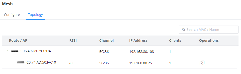
On this page, the user will be able to see the topology of the GWN access points when they are configured in a Mesh network. The page will display information related to the APs, like the MAC address, RSSI, Channel, IP Address, and Clients. It will also show the cascades in the Mesh.
Mesh Topology
SWITCH MANAGEMENT
Switch management involves overseeing and controlling network switches through the GCC601x. This includes configuring, monitoring, and optimizing switches for efficient resource allocation and network troubleshooting. GCC601X(W) simplifies switch management, allowing organizations to adapt their network infrastructure dynamically without significant physical hardware changes, enhancing agility, and enabling on-demand service delivery.
The following GWN78xx switches can be managed by the GCC device:
GWN7801(P)/7802(P)/7803(P) on firmware 1.0.5.34 or above.
GWN7811(P)/7812P/7813(P)/7830/7831 on firmware 1.0.7.50 or above.
GWN7806(P)/7816(P)/7832 on firmware 1.0.9.15 or above.
GWN7821P/7822P on firmware 1.0.13.18 or above.
GWN7710R/7711(P) on firmware 1.0.7.3 or above.
Switch
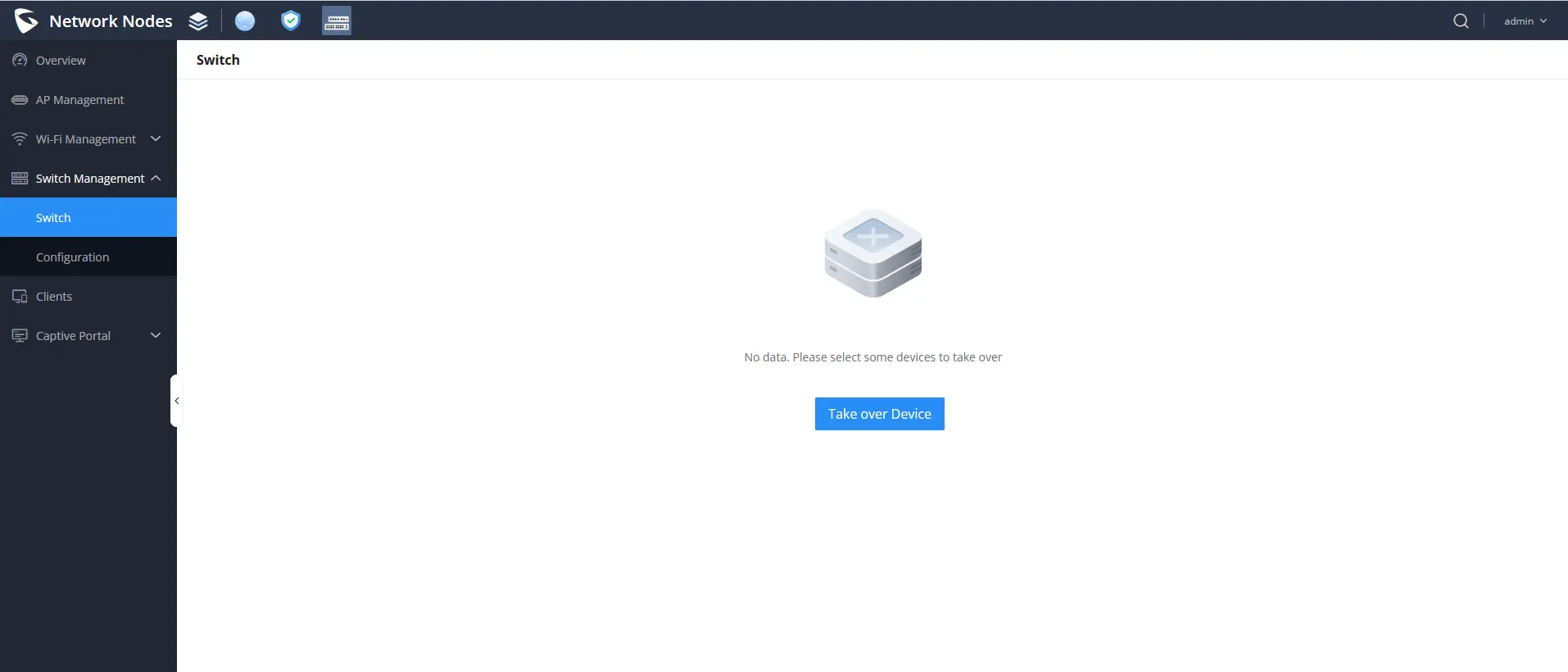
The user can take over GWN switches to the GCC601x network nodes. The way this works is by having devices nearby discovered using an ARP scan protocol, by entering the switch’s initial login Password to take over the configuration of those switches.
Taking over a switch
Take over Device
Among the discovered GWN78xx switches, you can choose the device that you want to take over or configure, to do:
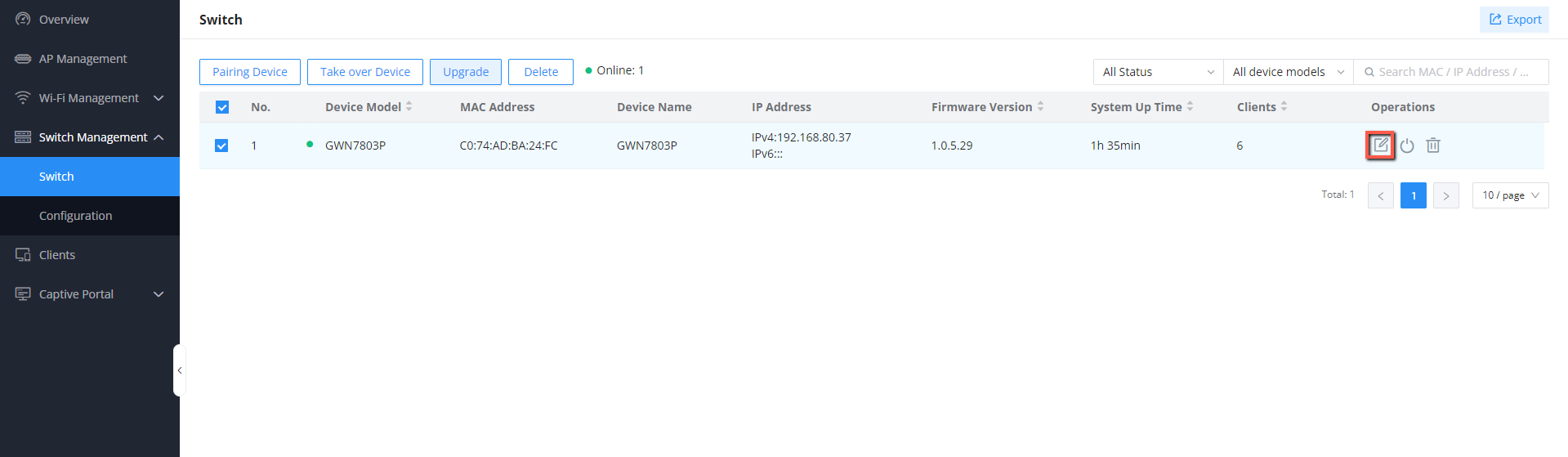
Go to Switch Management → Switch.
Click the icon to display the Takeover device settings.
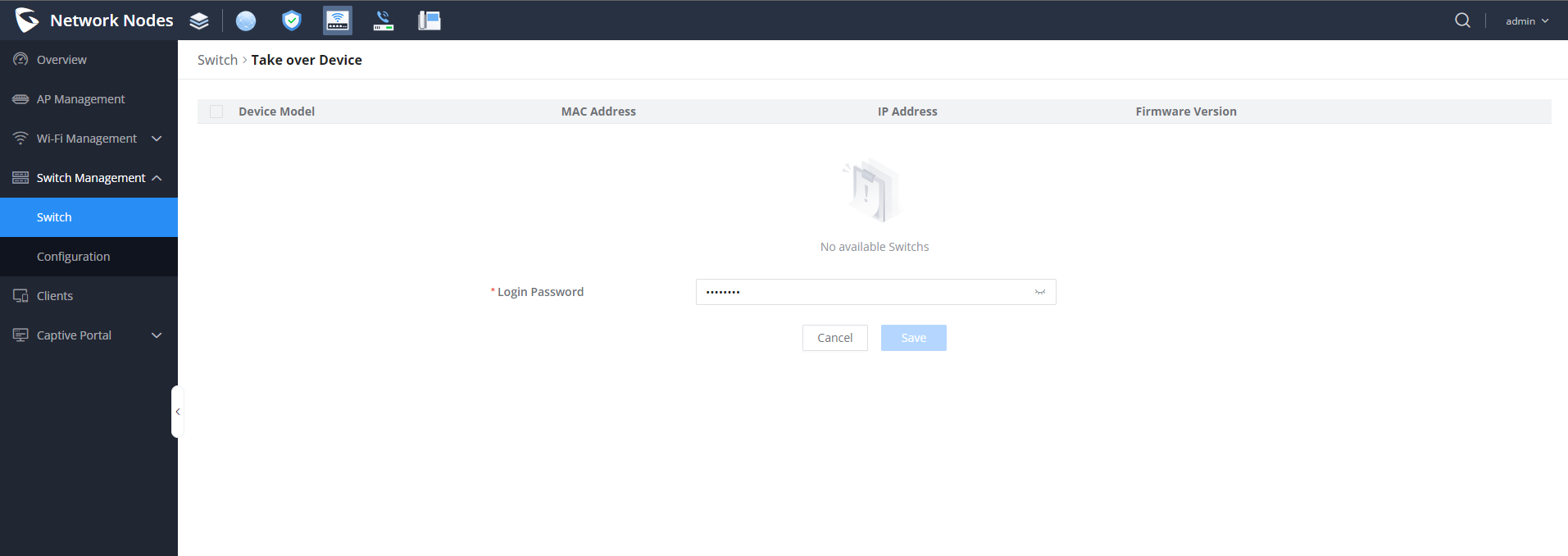
From the list of displayed GWN78xx switches, choose the GWN78xx you want to take over.
Enter its initial Login Password. (The one found on a sticker on the unit itself)
Click save to access the settings parameters of the GWN switch.
Taking over a switch
Reboot the device
To reboot the GWN78xx, select the GWN switch, then click on the icon
Upgrade the device
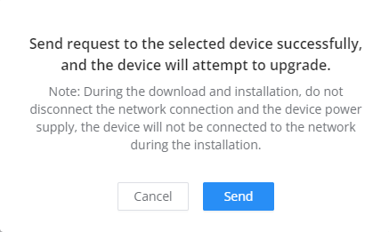
To upgrade the GWN switch, select the device, then click
Configuration
This section will contain the individual and global Switch configuration as well as the Port Profile settings. Each section will have its configuration parameters.
Individual Switch Configuration
The individual switch configuration refers to the different settings and parameters that can be defined on each switch individually. To configure this, select the desired switch, then click the icon
The following parameters will appear :
Device Name
Configures the device display name
Device Remarks
Contains additional information about the device
Device Password
Sets the device SSH remote login password and the device web login password.
RADIUS Authentication
Selects the RADIUS server that will be used for the authentification
Add VLAN Interface
VLAN
Selects the VLAN ID that will be used by the switch, Only one VLAN interface can be created per VLAN ID, so the used VLAN ID can no longer be selected.
IPv4 Address Type
Selects whether the switch will have its IP learnt statically or dynamically via DHCP
IPv4 Address / Prefix Length
Defnes the VLAN IPv4 address and its subnet mask
IPv6
Enables/disables IPv6
Link-Local Address
Configures whether IPv6 address is automatically assigned to interfaces within the VLAN, or manually configured
IPv6 Address/Prefix Length
Defines the VLAN IPv6 address and its subnet mask
Global Unicast Address
Stateful DHCPv6: Obtains IPv6 addresses and prefixes through the DHCPv6 server. Stateless DHCPv6: Provides prefixes, DNS, etc. according to router advertisements; DHCPv6 only provides other configuration information, it does not assign addresses, and needs to use the prefix of RA packets for address assignment. Stateless automatic configuration: Formed using the EUI-64 format, DHCPv6 only generates the first 64 bits of the address, with a fixed prefix length of 64. SLAAC (Stateless Address Autoconfiguration): allows devices to automatically configure their IPv6 addresses based on the network prefix received from the router advertisements, simplifying network setup and management within the VLAN without the need for manual address assignment or DHCP servers.
Global Switch Configuration
The Global switch configuration will contain parameters that will be applied to multiple GWN switches added
RADIUS Authentication
Radius Authentication
Select a Radius server or click Add New RADIUS to create a new server
Add RADIUS Authentication
Name
Defines the name of the RADIUS Server
Authentication Server
The “Authentication server” in RADIUS sets the server responsible for verifying user credentials during network access attempts.The authentication server(s) will be used in the displayed order (top to bottom), and RADIUS servers will be used after these authentication servers, you can define the server address , port number and secret key in the authentification server, you can define up to two authentification servers.
RADIUS Accounting Server
The RADIUS accounting server specifies the server responsible for logging and tracking user network usage data. you can define up to two RADIUS Accounting Servers
RADIUS NAS ID
Configure the RADIUS NAS ID with up to 48 characters. Supports alphanumeric characters, special characters “~! @ # ¥%&* () -+=_” and spaces
Attempt Limit
Sets the max number of packet sending attempts to the RADIUS server
RADIUS retry timeout (s)
Sets the max time to wait for RADIUS server response before resending RADIUS packets
Accounting Update Interval (sec)
Sets the frequency for sending accounting updates to the RADIUS server, measured in seconds. Enter a number from 30 to 604800. If the external splash page has also configured this, that other value will take priority.
Voice VLAN
Voice VLAN
Toggle voice VLAN on/off.
Multicast
IGMP Snooping VLAN
Select the IGMP Snooping VLAN.
MLD Snooping VLAN
Select the MLD Snooping VLAN.
Unknown Multicast Packets
Configures how the switch (IGMP Snooping/MLD Snooping) handles packets from unknown groups, the available options are to either drop the packets or flood the network by the packets, it is recommended to set it to “Drop”
DHCP Snooping Settings
DHCP Snooping
Toggle DHCP Snooping on/off, if enabled, select the VLAN on which the DHCP Snooping will be applied
802.1X
VLAN
Configures whether to enable the guest VLAN function for the global port.
Other
Jumbo Frame
Enter the size of the jumbo frame. Range: 1518-10000
Port Profile
The port profile is a configuration that can be used to apply many settings to a switch port at once, for quick batch setting changes.
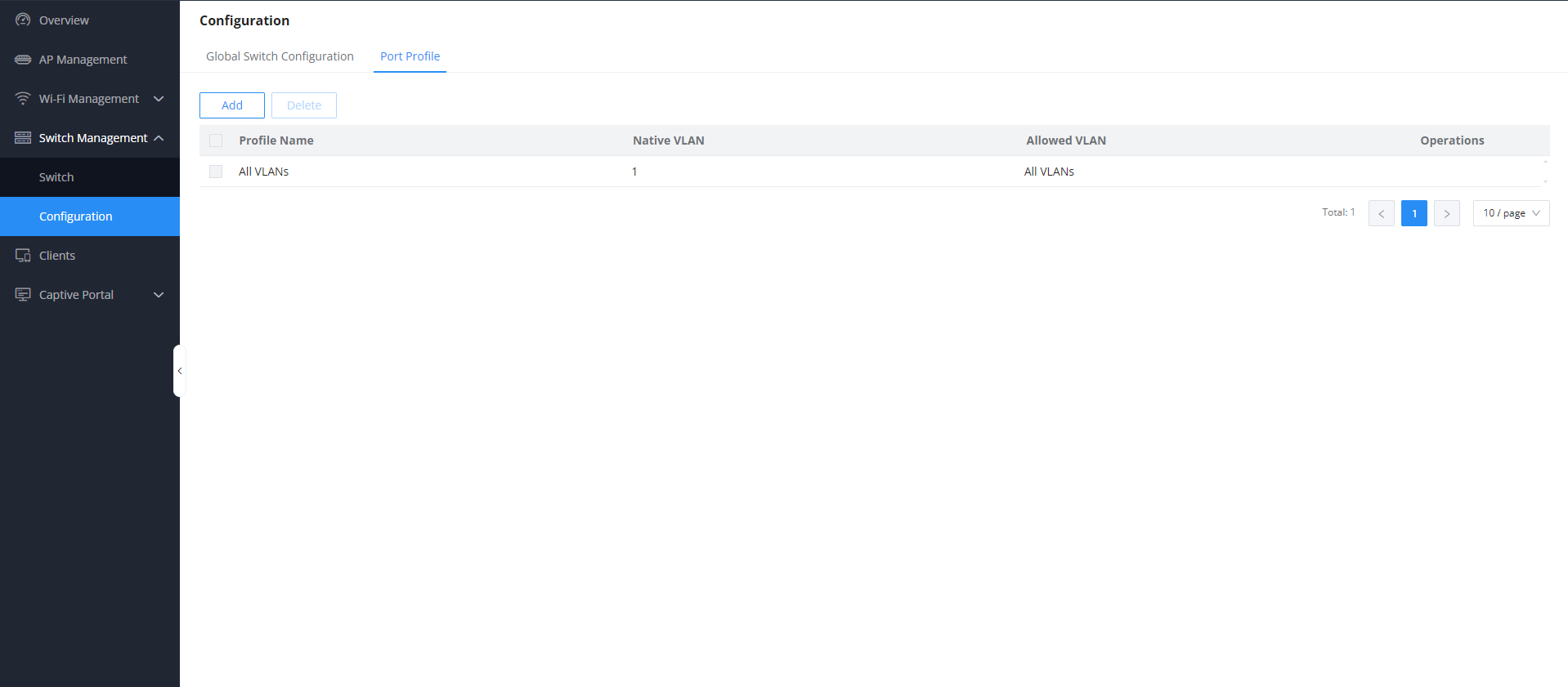
By default, you can find a non-editable Port Profile named “All VLANs”; this setting is the default setting and is applied on all connected ports on any added switch
To create a new Custom Port profile, click on the icon
Port Profile Configuration
To create a new Port Profile or edit an existing one, please navigate to Web UI → Settings → Profiles page → Port Profile section.
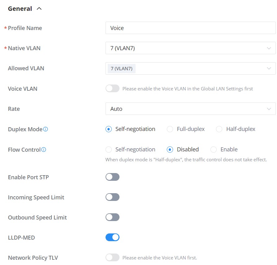
Add port profile General
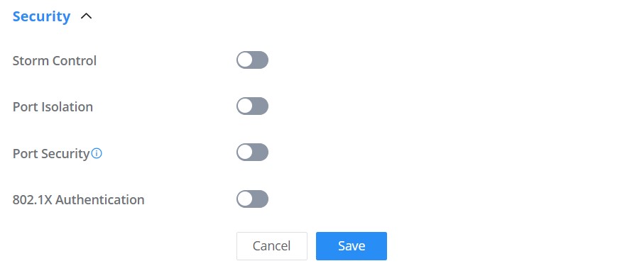
Add port profile Security
General
Profile Name
Specify a name for the profile.
Native VLAN
Select from the drop-down list the native VLAN (Default LAN).
Allowed VLAN
Check the allowed VLANs from the drop-down list (one VLAN or more).
Voice VLAN
Toggle ON or OFF Voice VLAN.
Note: Please first enable the Voice VLAN in the Global LAN Settings.
Speed
Specify the rate (port speed) from the drop-down list.
Duplex Mode
Select the duplex mode:
Auto-negotiation: The duplex status of an interface is determined by auto-negotiation between the local port and the peer port.
Full-duplex: Force full-duplex, and the interface allows sending and receiving data packets at the same time.
Half duplex: Force half duplex, and the interface only send or receive packets at a time.
Flow Control
When enabled, if congestion occurs on the local device, the device sends a message to the peer device to notify it to stop sending packets temporarily. After receiving the message, the peer device stops sending packets to the local device.
Note: When duplex mode is “Half-duplex”, the traffic control does not take effect.
Ingress
Toggle ON or OFF the incoming speed limit.
CIR (Kbps)
Configures the Committed Information Rate, which is the average rate of the traffic to pass through.
Egress
Toggle ON or OFF the outbound speed limit.
CIR (Kbps)
Configures the Committed Information Rate, which is the average rate of the traffic to pass through.
LLDP-MED
Toggle ON or OFF the LLDP-MED.
Network Policy TLV
Toggle ON or OFF the network policy TLV.
Security
Storm Control
Toggle ON or OFF storm control.
Port Isolation
Toggle ON or OFF port isolation.
Port Security
Toggle ON or OFF port security.
Note: after enabled, start MAC address learning including the dynamic and static MAC addresses.
Maximum number of MACs
Specify the maximum number of MAC addresses allowed.
Note: after the maximum number is reached, if a packet with a non-existing source MAC address is received, regardless of whether the destination MAC address exists or not, the switch will consider that there is an attack from an illegal user, and will protect the interface according to the port protection configuration.
Sticky MAC
Toggle ON or OFF Sticky MAC.
Note: after enabled, the interface will convert the learned secure dynamic MAC address into Sticky MAC. If the maximum number of MAC addresses has been reached, the MAC addresses in the non-sticky MAC entries learned by the interface will be discarded, and whether to report a Trap alert is determined according to the port protection configuration.
802.1X Authentication
Toggle ON or OFF 802.1x authentication.
User Authentication Mode
Select the user authentication mode from the drop-down list
Mac-based: allows multiple users to authenticate without affecting each other;
Port-based: allows multiple users to be authenticated. As long as one user passes the authentication, other users are exempt from authentication.
Method
Select the method from the drop-down list.
Guest VLAN
Toggle Guest VLAN ON or OFF.
Note: Enable the Guest VLAN in the Global LAN Settings first.
Port Control
Select the port control from the drop-down list:
Disabled
Mandatory authentication
Mandatory non-authentication
Automatic
Re-authentication
Configures whether to enable re-authentication for the device connected to the port.
Add Port Profile
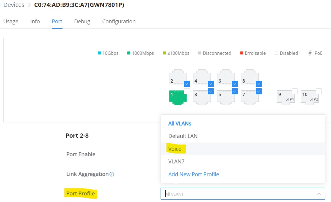
Once the Port profile is added, the user can apply it on a GWN device/device group ports (ex, GWN switches).
Under theDevices page, select the relevant device, and under the Port tab, select the ports, then apply the Port Profile to these ports. Please refer to the figure below:
GWN Switch Port
CLIENTS
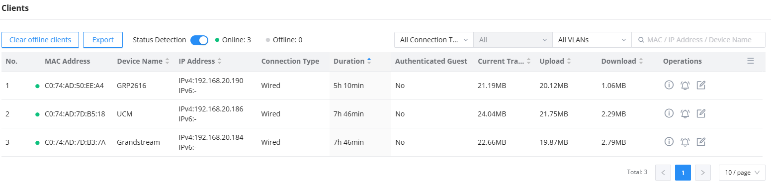
The Clients page keeps a list of all the devices and users connected currently or previously to different LAN subnets with details such as the MAC Address, the IP Address, the duration time, the upload and download information, etc.
The clients’ list can be accessed from GCC601x’s Web GUI → Clients to perform different actions for wired and wireless clients.
Click on “Clear offline clients” to remove clients that are not connected from the list.
Click on the “Export” button to export the client list to a local device in an EXCEL format.
Please refer to the figure and table below:
Clients Page
No.
Indicates the row number for the client entry.
MAC Address
This section shows the MAC addresses of all the devices connected to the router.
Device Name
This section shows the names of all the devices connected to the router.
VLAN
Displays the VLAN the client connected to.
Port
This section shows the specific physical port on the router or switch that a wired device is connected to.
IP Address
This section shows the IP addresses of all the devices connected to the router.
Connection Type
This section shows the medium of connection that the device is using.
There are two mediums which can be used to connect:
Wireless: Using an access point with the router.
Wired: Using an ethernet wired, either connected directly to one of the router’s LAN ports, or through a switch.
Radio/Channel
If device is connected through an access point, the router will retrieve the information of which channel the device is connected to.
SSID Name
If device is connected through an access point, the router will retrieve the information of which SSID the device is connected to.
Associated Device
In case of an access point or an access point with the router, this section will show the MAC address of the device used
Duration
This indicates how long a device has been connected to the router.
Authenticated Guest
Indicates whether the connected device has successfully completed authentication through the Captive Portal (e.g., via voucher code or splash page). Displays as “Yes” or “No”.
Identity Name
Displays the specific user account or identity bound to the client device. This field is typically populated when the network utilizes enterprise-level authentication, such as 802.1X/RADIUS.
RSSI
RSSI stands for Received Signal Strength Indicator. It indicates the wireless signal strength of the device connected to the AP paired with the router.
Station Mode
This field indicates the station mode of the access point.
Total
Total data exchanged between the device and the router.
Upload
Total uploaded data by the device.
Download
Total downloaded data by the device.
Current Rate
The real time WAN bandwidth used by the device.
Link Rate
This field indicates the total speed that the link can transfer.
Manufacturer
This field indicates the manufacturer of the device.
OS
This field indicates the operating system installed on the device.
Clients Page
Edit Device
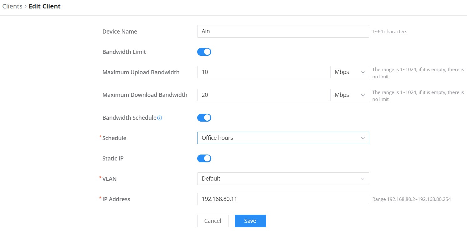
Under the operations column, click on the“Edit” icon to set the name of the device, and assign a VLAN ID and static address to the device. It’s also possible to limit bandwidth for this exact device and even assign a schedule to it from the list. Refer to the figure below:
Edit Device
Delete Device
To delete a device, go to the Operations column and click the button , then click “Delete“. Please note that you can only delete the offline devices; the online devices cannot be deleted.
Device Info
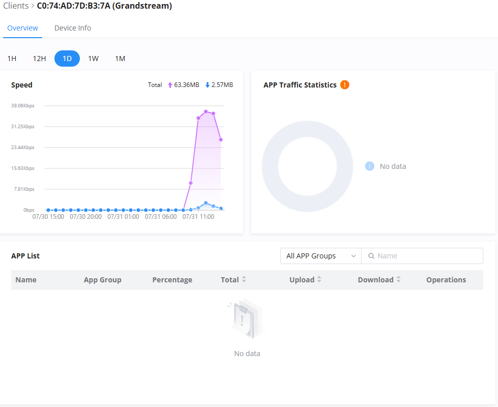
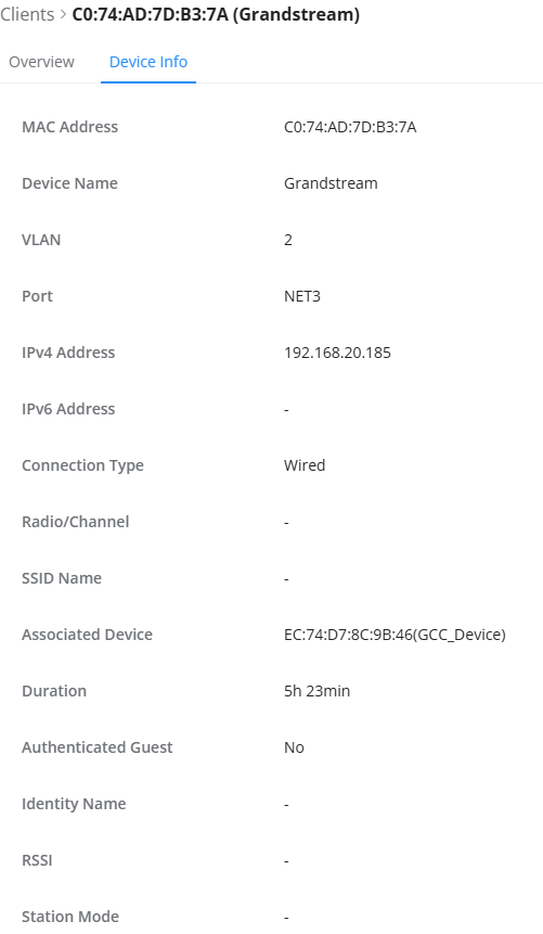
To access the information regarding a specific device, click on .
Device Overview
Device Info
CAPTIVE PORTAL
The Captive Portal feature on GCC6000 series devices allows administrators to display a landing page that users must interact with before gaining access to the Internet. This is typically used for login, terms of service acknowledgment, or redirection.
Captive portal can be applied to both wireless (SSID-based) and wired (VLAN-based) clients:
Wired clients: Enable the captive portal under Networking → Network Settings → LAN → Edit VLAN → Enable Captive Portal.
Captive Portal policies are managed from the GCC6000 Web UI under the Captive Portal section.
Policy
Users can customize a portal policy on this page. Click on the “Add” button to add a new policy or click on “Edit” to edit a previously added one.
Policy page
Policy page
If the user clicks on “Bypass Splash Page“, they can choose to exclude devices either by selecting from available connected devices or by manually entering MAC addresses.
Bypass Splash Page
The policy configuration page allows for adding multiple captive portal policies that can be applied to both SSIDs and VLAN interfaces. Each policy includes options for different authentication types and behavior customizations.
Policy Name
Enter a policy name.
Splash Page
Internal
External
Client Expiration
Specify the expiration time for client network connection. Once timed out, client should re-authenticate for further network use.
Client Idle Timeout (min)
Specify the idle timeout value for guest network connection. Once timed out, guest should re-authenticate for further network use.
Daily Limit
When enable, the client is only allowed to access once a day.
Splash Page Customization
Select the customized splash page.
Login Page
Set portal authentication through the page to automatically jump to the target page.
HTTPS Redirection
If enabled, both HTTP and HTTPS requests sent from stations will be redirected by using HTTPS protocol. And station may receive an invalid certification error while doing HTTPS browsing before authentication. If disabled, only the http request will be redirected.
Secure Portal
If enabled, HTTPS protocol will be used in the communication between STA and router. Otherwise, the HTTP protocol will be used.
Pre Authentication Rule (sec)
Set pre authentication rules, allowing clients access some URLs before authenticated successfully.
Post Authentication Rule (sec)
Set post authentications to restrict users from accessing the following addresses after authenticating successfully.
Bypass Splash Page
Allows devices in the selected MAC group to bypass the captive portal entirely. You can create MAC groups manually or select from connected devices.
Policy page
Splash Page
The splash page allows users with an easy-to-configure menu to generate a customized splash page that will be displayed to users when trying to connect to the Wi-Fi.
On this menu, users can create multiple splash pages and assign each one of them to a separate captive portal policy to enforce the selected authentication type.
The generation tool provides an intuitive “WYSIWYG” method to customize a captive portal with a very rich manipulation tool.
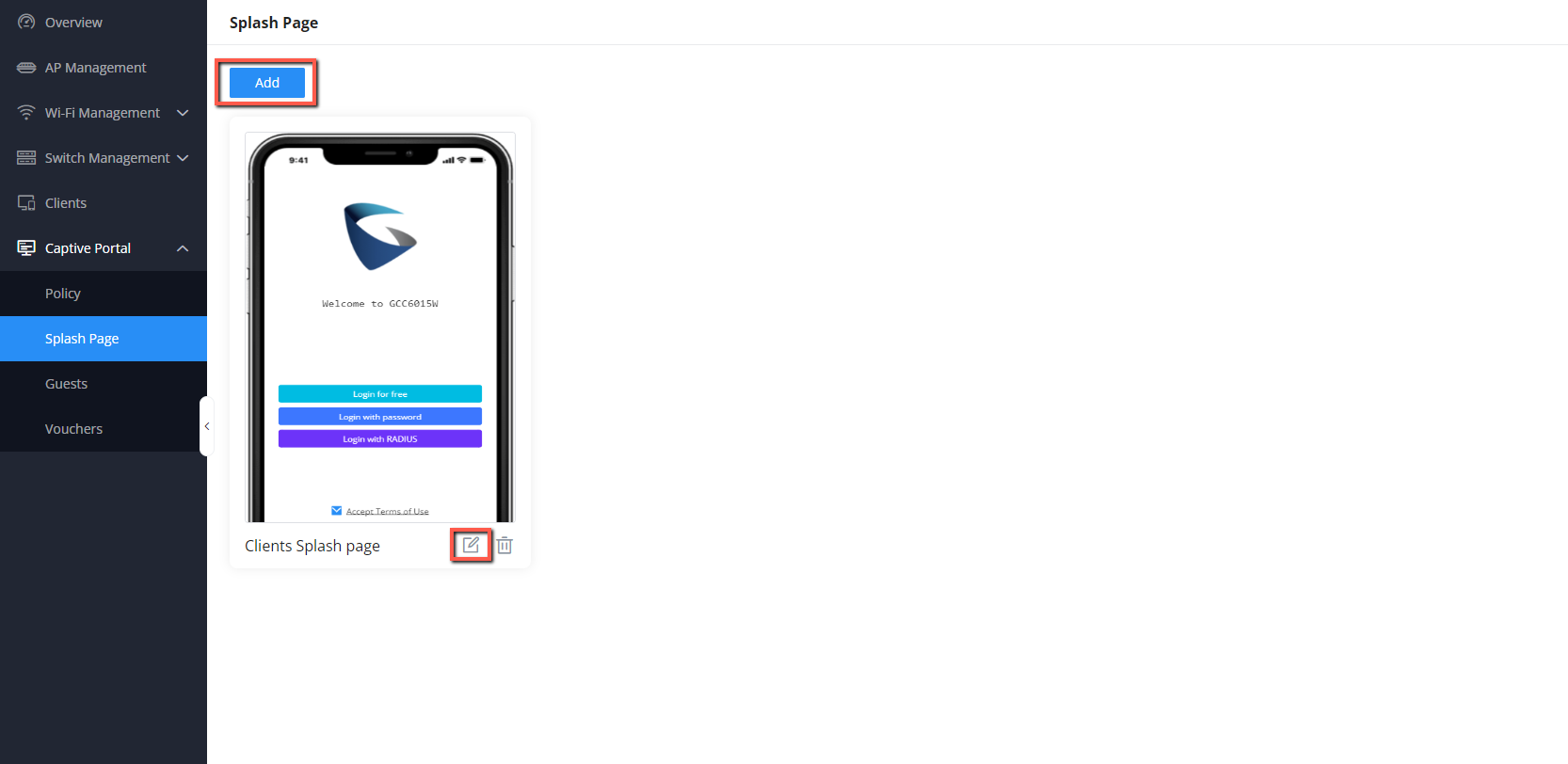
To add a splash page, click Add” button or click the “Edit” icon to edit a previously added one.
Splash Page
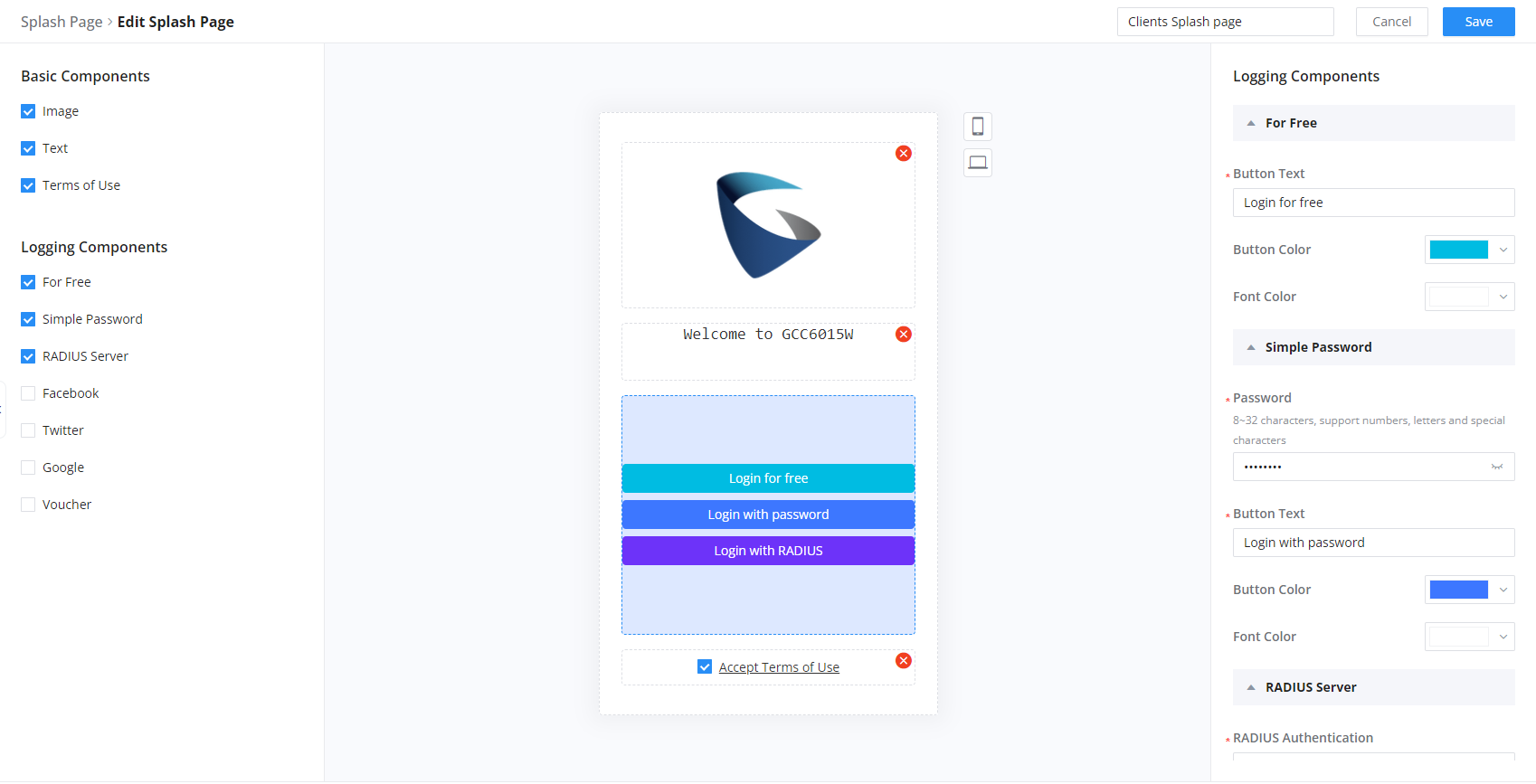
Users can set the following:
Authentication type: Add one or more ways from the supported authentication methods (Simple Password, Radius Server, For Free, Facebook, Twitter, Google, and Voucher).
Set up a picture (company logo) to be displayed on the splash page.
Customize the layout of the page and background colors.
Customize the Terms of Use text.
Visualize a preview for both mobile devices and laptops.
Addedit a Splash page
Guests
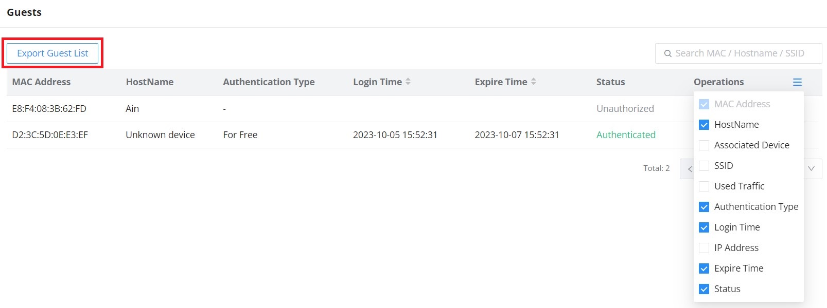
This page displays information about the clients connected via the Captive portal, including the MAC address, Hostname, Authentication Type, etc.
To export the list of all guests, please click on the “Export Guest List” button, and then an EXCEL file will be downloaded.
Guest Page
Vouchers
The Voucher feature will allow clients to have internet access for a limited duration using a code that is randomly generated from the platform controller.
As an example, a coffee shop could offer internet access to customers via Wi-Fi using voucher codes that can be delivered on each command. Once the voucher expires, the client can no longer connect to the internet.
Note that multiple users can use a single voucher for connection, with the expiration duration of the voucher that starts counting after the first successful connection from one of the users who are allowed.
Another interesting feature is that the admin can set data bandwidth limitations on each created voucher depending on the current load on the network, users’ profile (VIP customers get more speed than regular ones, etc.…), and the internet connection available (fiber, DSL or cable, etc.…) to avoid connection congestion and slowness of the service.
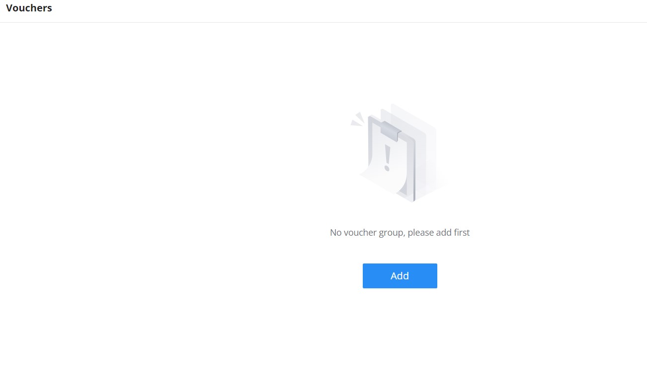
Click on the“Add” button to create a voucher group.
Voucher page
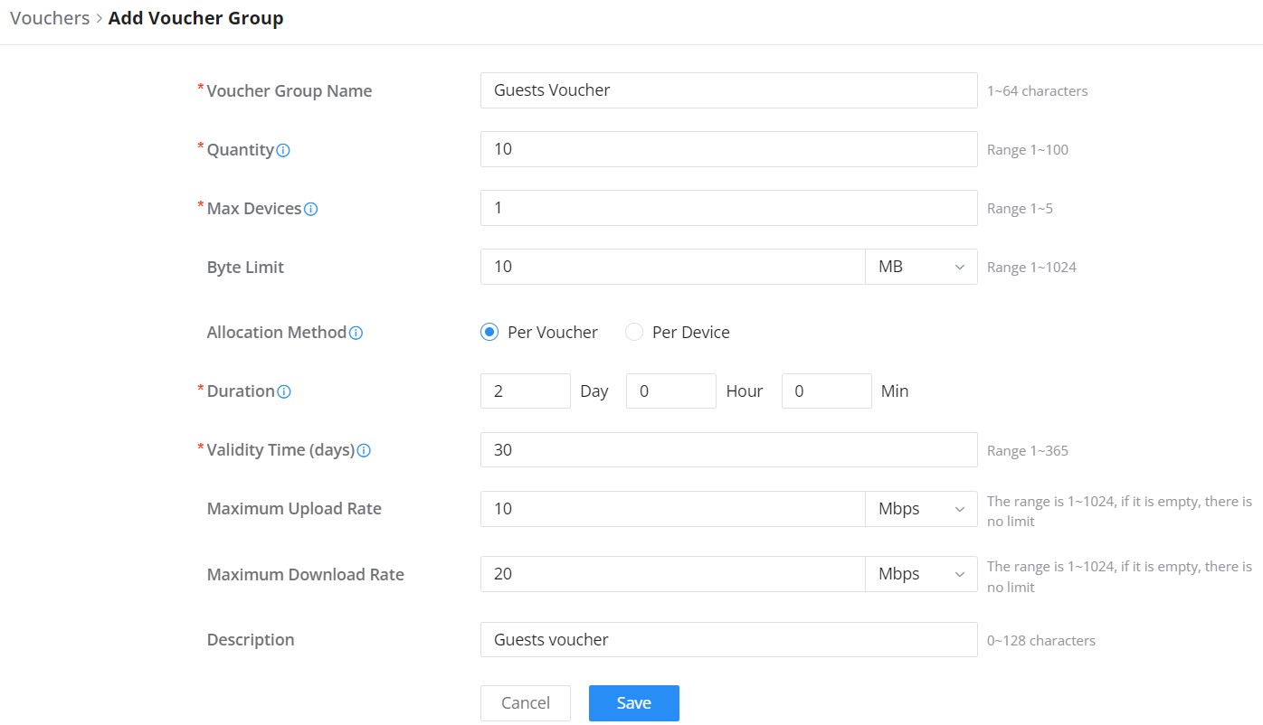
Please refer to the figure below when filling in the fields.
AddEdit Voucher
Note:
Clients connected through captive portals, including vouchers, will be listed on the Guests page under Captive Portal → Guests.
Add Voucher Group
Voucher Group Name
Defines the Voucher Group Name
Quantity
Configures the quantity of vouchers to be created, Valid Range is 1-100 vouchers
Max Devices
Sets the maximum number of devices allowed for the created voucher (Based on MAC), the valid range is 1-5
Byte Limit
Defines the maximum amount of data (in bytes) that a user can transfer before their access is restricted or expires, this can be defines in MB or GB, and the range is 1-1024
Traffic Allocation Method
Defines the Allocation method
Per Voucher : The byte limit will be distributed to all devices within the voucher
Per Device : The total usage for each device is the byte limit
Duration
Defines the time limit for which the voucher is valid and can be used for accessing the network.
Valid Time (Days)
Configures how many days the voucher will be available for. After the expiration , the voucher becomes invalid.
Maximum Upload Rate
Defines the maximum speed at which data can be uploaded by the user accessing the network using the voucher.
Maximum Download Rate
Defines the maximum speed at which data can be downloaded by the user accessing the network using the voucher.
Description
Gives a specific description to the voucher created
PERMISSION MANAGEMENT
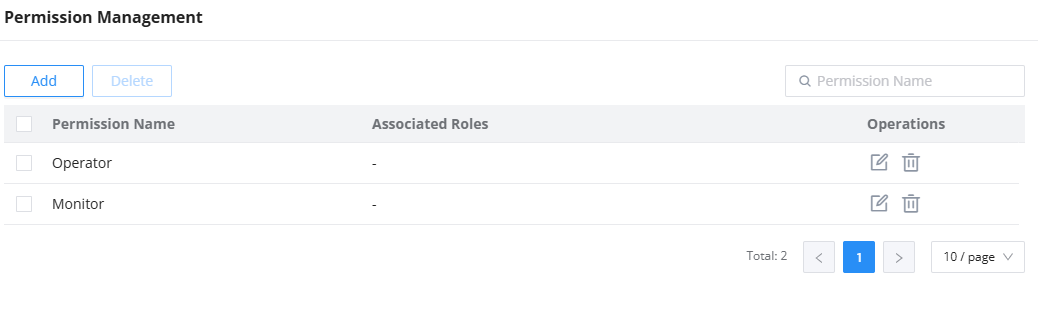
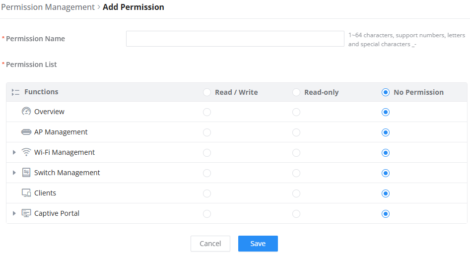
Permission Management allows the administrator to create multiple roles with different permissions, it allows creating roles with permissions of reading, or reading and writing privileges which allow monitoring, or monitoring and changing the settings on the Network Nodes module, respectively.
Permission Management
Click on button to add a new permission category. Enter the permission name, then select the functions, you can select to allow read, or read and write permissions.