
WLAN Technical Features
The growth of WLAN technology began in the mid-1980s, and its technical standards were mainly developed by the IEEE 802.11 working group. So far, the group has successively introduced many standards such as 802.11a/b/g/i/e/k/n/ac, and those standards has been perfected in terms of user bandwidth, wireless security, and manageability.
According to the latest commercial 802.11ac standard, the WLAN physical bandwidth can theoretically reach 1.7 Gbps. Currently, 802.11ac mainstream products can achieve a bandwidth of up to 866 Mbps (2 spatial streams) / 1.3 Gbps (3 spatial streams), and the APs with 802.1ac support have become the first choice for WLAN deployment.
This document describes the problems encountered in the deployment of 802.11ac enterprise-class wireless networks and provides solutions from the perspective of 802.11ac technical details.
This document applies to people: enterprise wireless network integrator, wireless network operation and maintenance administrator.
WLAN Product Introduction
Grandstream offers 802.11ac series wireless products, including GWN7610, GWN7600 and GWN7600-LR product features and applications as shown in Table 1 below:
| Product | Model | Indoor/Outdoor | Feature Description | Application |
 | GWN7630 | Indoor, ceiling installation | 1. Support 802.11ac-wave2 2. Dual-band 4×4:4 MIMO, up to 2.33 Gbps. 3. Support 802.3af and 802.3at Power-over-Ethernet (PoE/PoE+) | Indoor installation for enterprise office, hotel, and etc. |
 | GWN7610 | Indoor, ceiling installation | 1. Support 802.11ac-wave1 2. Dual-band 3×3:3 MIMO, up to 1.75Gbps 3. Support 802.3af and 802.3at Power-over- Ethernet (PoE/PoE+) | Indoor installation for enterprise office, hotel, and etc. |
| GWN7600 | Indoor, ceiling installation | 1. Support 802.11ac-wave2 2. Dual-band 2×2:2 MIMO, up to 1.27Gbps 3. Support 802.3af and 802.3at Power-over- Ethernet (PoE/PoE+) | Indoor installation for enterprise office, hotel, and etc. |
 | GWN7600LR | Outdoor, pole installation | 1. Support 802.11ac-wave2 2. Dual-band 2×2:2 MIMO, up to 1.27Gbps 3. Support 802.3af and 802.3at Power-over- Ethernet (PoE/PoE+) | Outdoor installation for squares, park and etc. |
WLAN PLANNING AND DEPLOYMENT
The Importance of Planning
With the tremendous growth of WiFi clients and mobile Internet applications, wireless LANs have evolved from pursuit of connectivity and coverage to the goal of high-capacity access.
High capacity is meant to support as many wireless clients as possible, and guarantees the experience of its key business applications. This is not easy to do.
The process of wireless network deployment as planning construction deployment network optimization operation and maintenance is very different from our previous experience on the wired network. In the actual deployment, there is such a typical case:
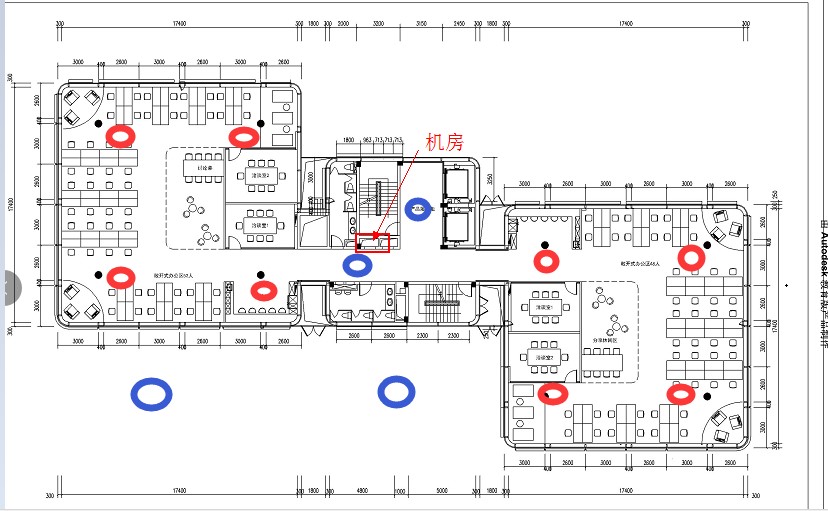
Figure 1 is a floor plan of an Internet company (totally they have 3 floors), each floor has about 100 workstations, each station uses 2-3 terminals, including smart phones, APP tests and office laptops, etc.
By conservatively estimation, there could be 250 terminals per layer.
The company requires wireless deployment for all office phone and laptops, and requires seamless roaming. In order to achieve the strongest signal coverage, the administrator deployed access points with full coverage of all workstations (shown by red dots), and added access point installation for outdoor terraces, elevator halls and corridor (shown by blue dots).
As the result, Wi-Fi signal strength can be detected with over -50dBm at any location on this single floor.
Before the network deployment is delivered, people ran test at night time after work, and network speed can always reach to the full speed of their ISP bandwidth.
However, after the wireless network is put into use at daytime, the user experience is unexpected terrible, and employees continuously complain the slow network. However, the measured export bandwidth utilization on the ISP router is low. So, what is the problem?
Signal strength (dBm) is the basic requirement for guaranteed service. However, the service is not guaranteed to be good, even the signal quality is strong. Signal strength will finally be converted to SNR (signal-to-noise ratio, ie the difference between signal and noise, in dB), and then reflect on user experience.
How to understand the signal-to-noise ratio? For example, when you are at home, you can talk softly and whispering, but in a pop concert, you have to talk loudly to the person even next to you. The reason is, often times, and even if the signal is strong, but the background noise is also high, communication is still hard. Even more, this company has three floors, and all floors are deployed in a high density, while no RF power and channel planning were done!
When the network is put into operation, where does the noise come from?
Some of them come from some wireless devices, such as microwave ovens, Bluetooth phones, and nonWi-Fi co-frequency networks such as frequency hopping wireless networks, and radar interference, but many of them are derived from the “Friends Wi-Fi Network” and the system in the system. The samefrequency and adjacent-frequency interference of the manufacturer’s Wi-Fi network can also be subdivided into inter-AP interference, inter-terminal interference, and interference between terminals and APs, especially in multi-user and multi-path environments.
How to Plan Deployment
How to carry out reasonable planning and design?
For wireless LAN, the key is to increase the channel multiplexing efficiency and air interface utilization efficiency, thereby reducing media competition and radio frequency interference. The specific operation requires two steps:
First Step: Plan Efficient Channel Multiplexing and Minimize Channel Sharing
What is channel multiplexing?
Channel multiplexing is the use of non-overlapping channels for coverage to reduce the behavior of co-channel interference. Since the wireless spectrum resources are not infinite, it is necessary to use the channel (or channel combination) multiple times when implementing full coverage of the wireless network in enterprise deployment.
In the United States, for example, there are only 3 non-overlapping channels (CH1/CH6/CH11) in the 2.4 GHz band, and the resources are more abundant in the 5 GHz band. Under normal circumstances, there are 9 non-overlapping channels, respectively CH36/CH40/CH44/CH48, and CH149/CH153/CH157/ CH161/CH165.
However, in a high-density deployment, more than usual numbers of APs are required to offer connection to a large number of clients in a certain area.
In this case, efficient channel multiplexing is basically impossible to achieve on the 2.4GHz spectrum and can only be realized at 5 GHz with rich spectrum resources. Therefore, in a high-density environment, in order to improve the user experience, the 2.4G frequency band is often shut down to prevent user access.
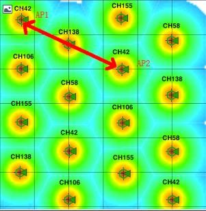
Figure 2 below is a schematic diagram of efficient channel multiplexing. AP1 and AP2 use the same frequency CH42 channel (that is, the center channel frequency of the 80MHz channel width). If the two APs can detect each other, they share the same channel and cannot transmit data at the same time.
However, the coverage of the two APs does not overlap, so the two APs will not hear each other. Therefore, the client connected to AP1 and Client2 connected to the same frequency of AP2 can simultaneously send to their respective APs. Data does not affect each other.
This picture down below is also a good example of channel multiplexing. In real deployment, channel usages should be planned in such principle.
How to achieve an efficient channel multiplexing of dense microcells deployment? There are few methods:
- Control the transmit power of the AP on a minimum level, as long as AP transmit power can cover the size of the planned cell.
- Turn off low data rates support, that is turning off 1, 2, 5.5, 11Mbps (without 802.11b) data rates. In a scenario where it is particularly necessary to control the size of the coverage cell, in addition to turning off the 802.11b rate, the number of 11ag management frames is limited to a minimum of 18 Mbps (or even 24 Mbps). It is actually limiting the AP’s cell size by controlling the lowest data connection rate (this feature will be supported in GWN future version).
It should be noted that this feature will affect the connection efficiency of clients from a distance away of the AP. This should only be considered when deploying the network at a high-density case without far distance connection requirement. Generally, the Wi-Fi network does not need to do this.
- In some specific scenarios, we can use buildings (eg, concrete thick walls, elevator shafts, pillars, or natural partitions such as large landscapes) to control the main lobe energy radiation of the wireless channel and let unintended direction of the target’s wireless energy attenuates rapidly, in order to complete the efficient multiplexing of the channel, prevent the omnidirectional antenna from spreading the signal everywhere, and reduce the possibility of co-channel interference.
Second Step: Improve the Air Interface Efficiency in a Single Channel Coverage Cell
To improve the efficiency of the air interface is actually to establish a higher data rate connection between the client and AP.
The client does not always establish the highest data connection rate anywhere within the coverage cell. Since 802.11 protocol dynamically adjusts the data rate established between client and AP to adapt the changing wireless environment. The farther the client is away from the AP, the lower the data rate can be established. Modulation mode always considers redundancy prior to performance.
Therefore, the most important thing for this case is to examine the location and behavior of target clients, and plan a reasonable AP installation place, so that clients can get as close as possible to the AP.
Significance of Radio Signal Parameter
Wireless networks have been closely integrated with people’s lives, work, and entertainment. However, users of WLAN wireless networks may think that wireless network should have the same stable as wired networks.
In fact, evaluating the performance of a wireless network is very different from evaluating the performance of a wired network. For example, if your laptop is connected to a wired network switch through a network cable, the data connection rate between the links is 1000Mbps, then you will use the performance test tool to test the throughput of the physical link will basically get the same result, the physical layer efficiency is above 90%, and very stable. However, if your laptop is connected to the AP wirelessly, the data rate of the link may show 1300Mbps, but what the result will be if you run a throughput test tool?
You may only get about 65%, and this throughput result is only based on 1 on 1 connection between AP and client. As the number of terminals/clients increases, the aggregate throughput of all clients will continue to decline. The reasons for this phenomenon are:
- Objective factors such as unstable and unreliable air media;
- The wireless network uses the CSMA/CA mechanism for access, and data collision and access retreat are common events;
- The MAC layer uses an acknowledgment mechanism so that data retransmission is inevitable;
- In order to be compatible with old terminals such as 802.11a/n, the physical layer design increases the overhead of the leader
The 802.11 protocol exchanges a large amount of system overhead for reliability of the data transmission.
In addition, the diversity of the clients will also cause a huge difference in system throughput.
Let’s say we have an 802.11ac supported AP with three spatial streams is deployed on the 80MHz channel, and when the client also with three spatial streams (usually a laptop) connected, a 1300 Mbps connection data rate can be negotiated. But when a client (a smartphone or tablet) with single spatial stream connects to the AP, you can only establish a connection with data rate of 433 Mbps. Obviously, the huge difference in peak throughput between the two will affect the performance of the entire system.
In short, to ensure the performance and user experience of the wireless network. Its planning, design, and maintenance are very different from wired networks. So what parameters or key factors we need to focus on in wireless deployment?
SNR (Signal-to-Noise Ratio)
For the client, the most important indicator to evaluate its performance is the signal-to-noise ratio (SNR).
Following SNR, we can focus on the received signal strength and retransmission rate.
The signal-to-noise ratio is the difference between the signal and the noise floor. The larger the difference is, the better the signal quality will be. For example, if a client receives a signal strength of -65dBm, while the noise floor is -92dBm, the signal-to-noise ratio is -65dBm-(-92dBm)=27dB.
If the received signal strength of the client is -60dBm, the noise floor is -80dBm, and the signal-to-noise ratio is -60dBm-(-80dBm)=20dB. Although the received signal strength of the second example is stronger, its signal quality is poor.
We often encounter a misunderstanding that the stronger the signal, the better the signal quality, which is a wrong impression. The stronger signal does not necessarily mean a better performance, and at the same the noise is often stronger. The result is poor signal-to-noise ratio and poor signal quality.
It’s SNR that determines what channel bandwidth can be used, how many spatial streams, and what modulation method is going to be used. All these will determine the data rate of your connection. That is, the use of 80MHz channel width requires a much higher signal-to-noise ratio than the 20MHz channel width. Establishing three-space stream communication requires a higher signal-to-noise ratio than establishing a single spatial stream. And the same applies to the modulation method upon SNR requirement.
Furthermore, to establish a high data connection rate for traditional 802.11a/g clients and APs, 20 dB of SNR is generally required; 25 dB is required for 802.11n; and 30 dB or more is required for 802.11ac.
In general, you can follow the following guidelines to determine your SNR number readings:
- SNR > 40 dB, signal quality is excellent, client can always associate with AP, and the highest data connection rate can be established;
- SNR between 25-40 dB, signal quality is good, client can always associate with AP to establish a high data connection rate.
- SNR between 15-25 dB, signal quality is OK, client can always be associated with AP, and a good data connection rate can be established;
- SNR between 10-15 dB, signal quality is fair, client can be associated with AP but with a low data connection rate;
- SNR between 0-10 dB, signal quality is poor, client and AP can hardly associate each other.
How to effectively achieve high signal-to-noise ratio?
It is obviously not a good idea to simply increase the AP transmit power. The non-overlapping channels (or channel combinations) are limited. If more APs are deployed and the signal strength is increased, the chance of same-frequency interference will be increased. As a result, the overall network performance will be reduced. So, the most effective way is to reduce the noise.
Here is something you can consider:
- For the impact from neighborhood Wi-Fi, it is necessary to record the installation location of those access point, channel distribution, channel bandwidth and coverage field. All this will be used for your planning reference to avoid their interference.
- Plan and design your own network. Plan the installation location, channel frequency, and bandwidth, and transmit power accordingly. The goal is to avoid co-channel interference and adjacent-frequency interference.
- For interference from non-WiFi devices, use spectrum scanning equipment to discovery and remove them if necessary.
- Run survey after deployment and do optimization accordingly.
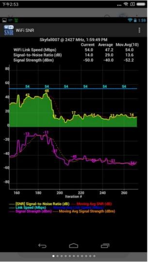
Some third-party cellphone app can be used to measure SNR: WiFi SNR.
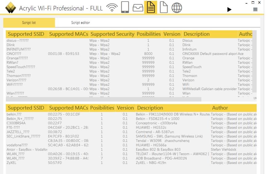
Besides, Acrylic_WiFi_Professional is a Windows software to run measurement through your PC/laptop:
Download link the software: https://www.acrylicwifi.com/en/wlan-wifi-wireless-network-software-tools/wifianalyzer-acrylic-professional/wifi-network-scanner-windows/
Channel Utilization
For coverage cells formed by APs, the most critical indicator for assessing their performance is Channel Utilization. Channel utilization reflects the busyness of the RF spectrum and the overall availability of the AP channel. Channel utilization is generally expressed as a percentage, and the larger the percentage value, the busier the channel. A channel utilization below 40%-50% indicates that the network performance is within an acceptable range.
The reason why channel utilization is important is that the channel utilization reflects all the influence of co-channel interference, adjacent-channel interference and non-WiFi network interference on the AP’s current channel. It also reflects the intensity of media competition and data transmission in the channel. This is a comprehensive indicator. When channel utilization is high (>70% or more), this channel is too crowded.
1. Where does channel utilization come from?
First, Wi-Fi client’s data transmission will occupy channel. The larger the data packet to be sent, the longer the time that the sender occupies the channel. Also, the slower the transmission rate is, the longer the time that the sender occupies the channel.
When the client is away from the AP, for example on the edge of the cellular coverage, the data negotiation rate drops to a lower value in order to compensate for the degradation of the signal strength. Although, this helps to improve the reliability of packet delivery, at the same time, it reduces the throughput of the device and results in an extra air time consumption, which cuts the air time that can be used for higher speed device transmission.
Therefore, if you want to improve channel utilization, effort of establishing a high data connection rate between the client and the AP is important.
Secondly, as the demand for high capacity wireless network, high density usage of APs and client devices causes more same-frequency interference and adjacent-channel interference. The channel utilization of this channel will also increase.
- Co-channel interference
When an AP is deployed on a particular channel, this AP will compete for the usage of the channel with all other Wi-Fi devices on the same channel within its radio range. However, Co-channel interference is relatively manageable compared to adjacent-frequency interference.
APs on the same channel can “hear” each other’s signals and will have to compete for transmitting on the channel. This limits the throughput that each AP can provide. What we need to do is to lower the signal impact between APs with a reasonable planning so that they do not affect the AP’s Clear Channel
Assessment (CCA) process
- Adjacent frequency interference
The neighbor channels on the 2.4GHz spectrum overlap with each other, and the adjacent channel interference on the 2.4GHz spectrum is particularly serious. The transmission of data on channel CH1 is unreadable for the adjacent channel CH4, which is equivalent to garbled (noise), and this will increase the background noise of CH4.
The adjacent channel interference in the 5GHz spectrum is mainly reflected in the interference between channels of different channel widths.
- Non-WiFi Interference (Other wireless appliances)
Non-WiFi Interference can come from Bluetooth devices, microwave ovens, digital enhanced cordless communication (DECT) phones, surveillance cameras, or any other device that uses the same RF frequency as the Wi-Fi channel but does not use the 802.11 protocol. This can also greatly increase channel utilization.
2. Where does channel utilization come from?
The channel utilization of 2GHz and 5GHz can be extracted through the GWNmenu program as follows:
- SSH login by WebUI user name and password. After login, “GWNmenu” will be shown as Figure 6 down below;
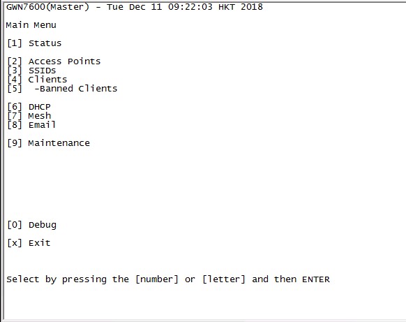
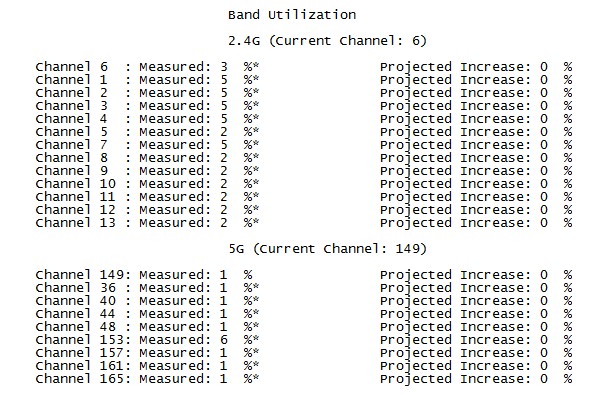
- Enter “9” to select Maintenance. After entering the page, enter “99” again, select “[99] Band Utilization”, wait for 10~15 minutes of channel scan time, and get channel utilization of 2GHz and 5GHz support channels. Rate information, as shown in Figure 7 below.
- Non-WiFi Interference (Other wireless appliances)
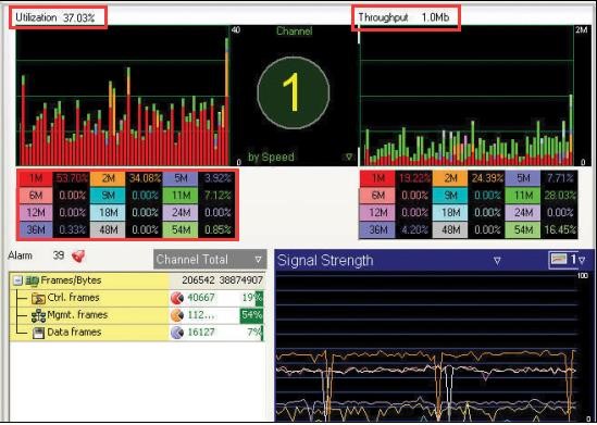
Specify the channel to view its utilization in real time. It can also indicate the wireless rate used by the 802.11 frame in the current channel. When the low-speed frame is large and the channel utilization is high, the external interference problem needs to be considered.
3. How to reduce high channel utilization
Usually, channel saturates when utilization is between [40%, 50%]. In this range, wireless network is still OK for most applications. But for latency-sensitive applications, such as VoIP, channel utilization above 30% may affect the user experience.
In general, the main methods to reduce high channel utilization are:
- Reduce the number of total SSIDs
Each additional SSID in the wireless network will bring a lot of air interface overhead. For example, if an SSID is enabled on an AP, the SSID has an own beacon frame plus its other management frames. The expense of occupying the channel is about 3% at a data connection rate of 1 Mbps. If an AP enables 3 SSIDs, the expense of the 1Mbps data connection rate will rise to about 9%. When you continuously cover the network, if the AP is in a contention collision domain with the co-channel AP, the channel utilization rate will be as high as 27%.
In addition, another reason for reducing the number of SSIDs is that some clients cannot handle a large amount of SSID information due to their own limitations. These devices may be locked during scanning a large number of SSIDs, and results in an association failure with targeting wireless network.
- Turn off the low rate connection (feature pending on GWN APs)
When the client is far away from the AP, the data connection rate is reduced by one or several levels, which causes same data amount will consume a longer period of time, and a higher channel utilization. Forbidding the low data rate force the wireless client to roam to a nearby reliable access point, so that this wireless client can communicate in a high data rate, which will reduce the channel utilization when same amount of data is transmitted.
The data rate determines the expense of the management frame occupied by the beacon. An example of same amount of data transmission. If the data rate is 1 Mbps, the channel expense is about 3%. If the data connection rate below 6 Mbps is turned off, and negotiated speed increases to 6 Mbps, the channel expense reduces to about 0.6%. Furthermore, if the data connection rate below 12 Mbps is turned off, then expense will be about 0.3%.
- Access control of clients and applications
High channel utilization also reflects the number of clients and application behavior.
If the client uses P2P software, it may results in a higher channel utilization than browsing simple web applications. These can be limited by features such as “client speed limit”
- Adjust the size of AP radio coverage cell
Adjusting the AP’s cell size can be achieved by reducing the transmit power of the AP or by forbidding the low-speed management frame. Reducing the transmission power of APs can reduce the visibility, and mutual interference between APs, and indirectly reduce the channel utilization for neighbor APs on the same channel. Another benefit of lowering APs’ transmission power is to balance the uplink and downlink signal strength. Usually AP’s downlink signal is much stranger than mobile end device’s uplink, and this will cause a phenomenon that mobile device can hear AP while AP can’t hear mobile device.
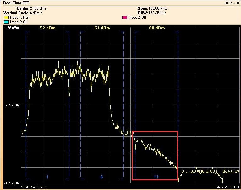
Another function of “turning off the low connection rate” mentioned in previous paragraph can also effectively control the cellular size of the AP. The figure below is an example:
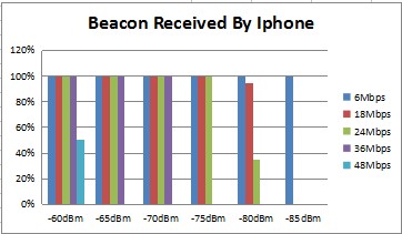
In this scenario, the access point has the connection rate below 24 Mbps closed. (18 Mbps and 24 Mbps are relatively stable connection rates. Please do not close it in real deployment.) By standing at the position of -80dbm, the probability of beacon being detected is reduced by a lot. So, it reduces the range indirectly. However, this feature will affect the client connection from the coverage edge and is only suitable for high-density AP deployment scenarios.
- Planning of channel multiplexing
Efficient channel planning, by avoiding the co-channel and adjacent channel interference, can greatly reduce the channel utilization of the working channel (see the section on co-frequency interference and adjacent-frequency interference mentioned above).
- Eliminate illegal devices or non-Wi-Fi devices in the same spectrum
Non-WiFi Interference is hard to eliminate during wireless network planning and designing, and it is also difficult to find, usually by capturing packets or spectrum scanning.
In real situation, you can first test in a near-end and then far-end for a throughput value. In the case of low throughput or abnormal fluctuations, make a comprehensive judgment of the integrated SNR and Channel Utilization data, and run wireless capture, if necessary, to confirm.
Impact of Client Performance
When designing and deploying and verifying wireless networks, we often focus only on the capabilities of offered wireless network on APs’ side and ignore the very important element of the wireless network – the wireless client.
Therefore, we must consider the capabilities and device behavior of target Wi-Fi clients when designing and deploying and verifying wireless networks.
The main differences in client capabilities (example):
- Does the client use a built-in network card or USB?
- Does the client support 2.4 GHz and 5 GHz dual bands?
- Which of 5 GHz channels does the client support?
- Client transmission power.
- Client receiving sensitivity.
- Does it support 40MHz, 80MHz channel width?
- The number of antennas for sending and receiving on client, and the number of supported spatial streams.
- Client antenna gain, antenna installation position.
- The number of the client can scan.
- Client support for air interface encryption?
The main differences in client behavior (example):
- Algorithm to select AP on initial connection?
- Roaming decision algorithm?
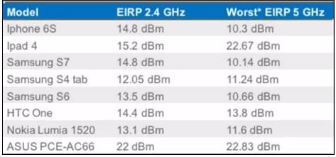
Among all these, the most related factors that need to be consider during Wi-Fi deployment planning is client’s transmission power.
Considering limited battery life of mobile device, the wireless client’s transmission power is usually set to low. In addition, the size of the wireless client is very small, which limits the space for antenna very much. As a result, the antenna gain of many clients is 0, and the transmission power is very small, which is as shown below:
The Wi-Fi system is bidirectional. If the transmit power of the AP is higher than that of the client, the downlink signal of the AP can reach the wireless client smoothly. However, the uplink signal of the wireless client cannot reach the AP effectively. Even the air signal reaches the AP, AP may not have enough signal-tonoise ratio to recognize the content.
Although the uplink traffic is the major direction in the wireless network communication, Wi-Fi uses a Layer 2 acknowledgment mechanism, such as acknowledgment (Ack) messages need to be transmitted on the reverse direction. If ACK fails, and the entire communication fails. In this case, the access point will be retransmitted until the retransmission limit is reached, and then the upper application will drop packets or even be interrupted.
In addition, for real-time voice and video application, the uplink and downlink traffic are basically the same, so application will be interrupted by this kind of mismatch between the transmission power of the access point and the client.
It’s like an adult talking to a child over a long distance. The adult’s voice is loud enough for child, but the child’s reply cannot be hear by the adult. Adult could only keep on repeating until he gives up.
In this case, AP’s strong transmit power is useless. It is critical to balance the uplink and downlink bidirectional links. Unfortunately, the first adjustment people are likely to take, when Wi-Fi communication goes bad, is to increase AP transmission power, and this doesn’t help at help.
Even worse, increasing power will not only increase the interference level of the entire network, but also easily cause all clients on this AP sticky from roaming. This is because many clients rely on the strength of the received signal for connection and roaming decisions. Furthermore, the sticky clients will cause much clients connection than expected, and may lead to system capacity overload on the AP.
So, the correct approach is: study the client’s behavior, roaming area, and analyze the indoor building partition, and then properly set the transmission power as low as possible while still providing enough coverage.
As a part of planning of wireless network deployment, it important to analyses the customer requirement.
So, in the early stage of planning, you will need to:
- Know target customer Wi-Fi client device by classifying the type, power level and behavior.
- Upgrade the client driver to the vendor recommended version if possible.
- Use dual-band client instead of 802.11a/b/g only clients if possible.
- Test the roaming capabilities of clients in your deployment.
How to Deploy with 802.11ac
As mentioned earlier, an important step in real deployment of WLAN is to improve the air efficiency in channel, that is, to establish a higher connection between the client and the AP. Compared to 802.11a/b/g/n, high date rate is also the advantage of 802.11ac.
Advantages and Features of 802.11ac
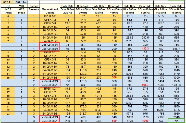
802.11ac technology alone cannot solve planning and deployment problems. To properly understand the role of 802.11ac, first, let’s look at how 802.11ac implementation boost the speed. In the case of the same number of spatial streams, the following are two main factors, as shown in Table 5:
- Wider channel width: increased from the maximum 40MHz of 802.11n to 80 MHz/160MHz
- Higher modulation: increased from 802.11n 64 Quadrature Amplitude Modulation (QAM) to 256 Quadrature Amplitude Modulation (QAM)
- Stronger modulation method
Wireless transmission is affected by a number of factors that can damage the RF signal quality and cause the receiver fail to read. So, each data bit is encoded into multiple bits before transmission. This way of adding redundant information to the data can improve the system’s ability to resist data corruption, which we call encoding. After the data is encoded, the radio transmitter performs carrier modulation on the data, and the modulation method adopted by 802.11n/ac is QAM.
The densest modulation method of 802.11n is 64 order QAM. 802.11ac uses a new scheme to achieve 256 order QAM, which contains 33% more data than 64-QAM into each constellation mapping point.
256-QAM corresponds to two new Modulation Coding Scheme (MCS 8 and MCS 9) that achieve the higher data connection rate than MCS 7 in the same air time. However, 256-QAM requires a more sensitive detection on phases and amplitudes in the modulation. Therefore, it is more sensitive to the noise in the environment and requires a cleaner signal with a higher signal-to-noise ratio (SNR).
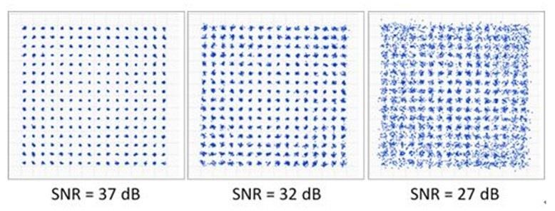
The following figure 10 is the required SNR value in the 256QAM modulation mode. When the SNR is less than 27dB, the bit mapping point on the constellation cannot be resolved at all, and the receiver cannot be correctly parsed. And this failure transmission will lead to retransmissions.
Therefore, in actual deployment, modulation high like 256QAM can only be achieved in a small distance range. This requires a full visual line of sight between the wireless access point and the client, and it is only possible to establish an MCS 8 or MCS 9 data connection rate within 10 meters. Otherwise it will drop to the lower data connection rate, such as MCS7 by 64-QAM modulation.
- Wider channel width
By combining channels into a wider channel, just like expanding highway lanes, the traffic volume per unit time will increase exponentially. The wider channel width is used in the spectrum, the more data can be transmitted.
Below is an example for US GWN model, 5GHz channel numbers and distribution maps (Figure 11):
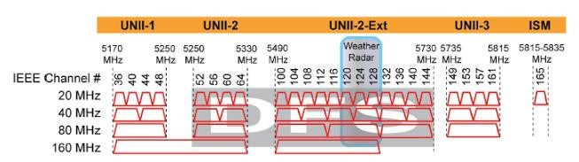
- 20MHz channel width: 9 available (CH36~48, CH149~CH165)
- 40MHz channel width: 4 available (CH38, CH46, CH151, CH159)
- 80MHz channel width: 2 available (CH 42, CH155)
- More spatial streams (NSS)
By 802.11ac standard, it can achieve up to 8SS (compared to the 4SS of the 802.11n standard, theoretically this is 100% growth). However, considering the production cost, and the size of Access Point, 2~3SS are commonly used. From the client device, 1 (smartphone) to 2 (tablet, notebook) space streams are common accepted.
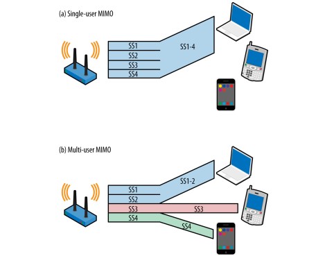
- Introducing multi-user multiple-input multiple-output (MU-MIMO)
MU-MIMO introduced by the second-generation 802.11ac product (ie 802.11ac Wave2) is not used to improve the connection speed, but to improve the transmission efficiency. To directly take advantage of MU-MIMO, it requires client to support 802.11ac Wave2 too.
Figure 12 is a diagram of downlink transmission of SU-MIMO and MU-MIMO, where SU-MIMO represents the first generation 802.11ac standard and MU-MIMO represents the second generation 802.11 standard.
However, MU-MIMO cannot solve all problems of Wi-Fi slowness. As mentioned, it only optimizes multi-user transmission efficiency. Below are some limitations:
- MU-MIMO requires protocol support on both wireless access points and wireless clients. However, there still a great number of user device without 802.11ac support. So, in most deployment scenario, access points are always facing hybrid terminals. Most of the time, multiple standard 802.11a/n/ac terminals work at the same time. In this case, AP must provide service on their supported protocol too, which makes it hard to fully utilize the features of 802.11ac Wave-2 and the AP cannot work in an optimal state.
- MU-MIMO can only improve the efficiency of downlink multi-user data transmission, and it is ineffective for the uplink direction.
- The number of clients supporting MU-MIMO for simultaneous downlink transmission cannot be greater than the number of antennas in the AP;
Below is a diagram of a SU-MIMO simple omnidirectional antenna comparing to a MU-MIMO beamforming (Figure 13).
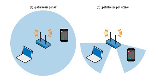
- In the process of simultaneous downlink data transmission, in order to avoid co-channel interference between MU-MIMO clients, these clients need to be separated in physical space to increase the anti-interference physical isolation.
- MU-MIMO is aiming at improving the multi-user downlink aggregation throughput, instead of ensuring each client’s peak throughput. For the client with unqualified SNR, transmission will automatically fall back to non-MU-MIMO (802.11ac wave1)
In summary, in the actual deployment environment of WLAN, high-capacity and high-concurrent access is the focus. MU-MIMO technology is designed for this. However, MU-MIMO technology in not an all in one solution, and reasonable planning and design is the key to take advantage of its benefit.
How to Deploy with 802.11ac Wireless Products
- Emphasis on planning and design
First step is to plan channel and channel bandwidth, transmit power, and reduce competition and radio frequency interference on the air, in order to implement an efficient channel multiplexing. Try to arrange your channels to avoid same frequency or adjacent frequency interference. Also, try to eliminate non-Wi-Fi system interference.
Second step is to increase the air efficiency within a single channel, that is, to establish a higher data connection rate between the client and the wireless access point.
In the case where the first step cannot be achieved, simply performing the 2nd step will not cause any great improvement in network performance!
- 802.11ac deployment common parameters
- Frequency band:
Compared with the 2.4G frequency band, the spectrum resources of the 5G frequency band are more abundant. In the US region, there are currently 9 available 20MHz channels.
A wide range of spectrum resources can be used to achieve efficient channel multiplexing. For a typical WiFi network, it is recommended that adjacent APs use different channel ranges, that is, AP1 uses
CH36~CH48 frequency band, and neighbor AP2 uses CH149~CH165 frequency band. There is as much channel isolation as possible between APs.
For some high-density scenarios, there are many clients, and the 2G itself spectrum may be extremely crowded. However, many clients may still connect to 2G, which will result in a poor user experience. At this time, it is recommended to enable band steering to 5G on dual-band SSID. Alternatively, you can even turn off the 2.4G band SSID if possible.
- Channel and channel bandwidth selection:
Compared with the 2.4G frequency band, the spectrum resources of the 5G frequency band are more abundant. In the US region, there are currently 9 available 20MHz channels.
A wide range of spectrum resources can be used to achieve efficient channel multiplexing. For a typical WiFi network, it is recommended that adjacent APs use different channel ranges, that is, AP1 uses CH36~CH48 frequency band, and neighbor AP2 uses CH149~CH165 frequency band. There is as much channel isolation as possible between APs.
For some high-density scenarios, there are many clients, and the 2G itself spectrum may be extremely crowded. However, many clients may still connect to 2G, which will result in a poor user experience. At this time, it is recommended to enable band steering to 5G on dual-band SSID. Alternatively, you can even turn off the 2.4G band SSID if possible.
802.11ac provides a wider channel width up to 160MHz, and the conventional bandwidth is 20/40/80MHz.
However, the use of wider channels is very hard to realize in real-world environments.
- 2.4G channel bandwidth problem
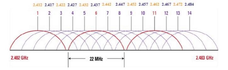
Before talking about the 802.11ac channel and channel bandwidth selection, let’s talk about the 2.4G 40MHz channel bandwidth. Figure 14 is the 2.4G channel distribution map. There are three non-overlapping 22MHz channels for planning and selection.
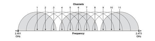
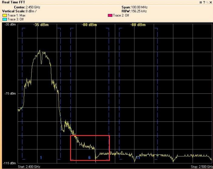
Figure 15 is the spectrum of the 20MHz channel. The signal of CH1 has been attenuated to below -100dBm in CH6, which has little effect on CH6. Therefore, we can achieve wireless coverage by multiplexing CH1/CH6/CH11 channels.
From the 802.11n MCS rate table query, we can see that 2.4G uses 40MHz other than 20MHz, the maximum physical layer rate is increased from 144.4Mbp to 300Mbps (in the case of 2SS), which is good.
However, look at the spectrum of the 40MHz channel (as shown in Figure 16 below). The 40MHz signal formed by the combination of CH1 and CH5 raises the noise floor of CH11 by 20dB!
As mentioned in the previous section of SNR, the signal quality is not to depended on the absolute signal strength, but on the difference between the signal strength and the noise floor.
According to the 802.11n specification, the AP and the client must work in the channel bandwidth mode of 20 MHz for the 2.4 GHz band by default. They can switch to the 40 MHz channel bandwidth mode by fulfill multiple rules. On the other hand, it also regulates the scenario for AP to return back to the 20 MHz.
Following are the rules:
- If an AP1 detects that there is another AP2 in the 40 MHz channel range, regardless of whether the wireless access point has client connection or transmission activity, it has to fall back to 20MHz mode;
- If the AP detects a client device that does not support the 40MHz channel (identified by the management frame flag sent by the client), it will fall back to 20MHz mode.
That is to say, the 40MHz channel bandwidth usage conditions are very demanding, so it is not recommended for use in enterprise deployments.
- 5G channel selection and channel bandwidth issues
When discussing 5G channel selection, two terms need to be introduced: primary channel and secondary channel, as shown in Figure 17 below:
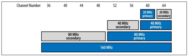
802.11ac adopts channelization design, and 20/40/80/160MHz is combined by channel channels with a bandwidth of 20MHz.
As the figure above, the combination is not arbitrary. CH56 and CH60 have no way to form a 40MHz channel, and CH56 can only be combined with CH52. Based on this channelization method, once the 20MHz primary channel and the channel width are specified, the working channel parameters are basically determined automatically.
The 20MHz primary channel is the channel number seen on the GWN’s WebUI page, while the 20MHz secondary is another 20MHz channel in the 40MHz channel. For example:
When an AP is configured with a channel bandwidth of 80 MHz and a primary channel of CH60, then CH64 automatically becomes its 20MHz secondary channel. The combined channel of CH60 and CH64 (40MHz bandwidth) automatically becomes 40MHz primary. Then CH52 and CH56 will automatically become 40MHz secondary.
So, what is the difference between 20MHz primary and 20MHz secondary?
In 5G, 802.11ac is designed with backward compatibility. Management or control frames, such as beacon frames, are transmitted at a rate with 802.11a supported. That is, those frames are only sent in 20MHz primary channel, while the secondary channel is an extension. When the channel is idle, it can be used to increase the transmission data rate. However, idle channel detection is required to find out if they are accessible.
a) Basic channel access rules
- To send 20MHz frame only on a 20MHz primary channel. It only requires performing CCA idle detection on the 20MHz primary channel, for example, CH60.
- To send 40MHz frame on the 40MHz primary channel. It requires idle detection on both 20MHz primary and secondary channel. In above example, CH60 and 64 both are idle.
- To send 80MHz frames on the 80MHz primary channel. It requires 40MHz primary and 40MHz secondary both are detected as idle, and pass CCA check, for example, CH52~64 are all idle.
- To send 160MHz frames on the 160MHz channel. It requires 80MHz primary and 80MHz secondary to remain idle, and pass CCA check, for example, CH36~64 are idle (GWN7630 will provide support 160MHz channel width).
The CCA sensitivity threshold is listed in Table 6, which provides the signal and energy detection threshold for the primary and secondary channels:
Channel detection includes signal threshold detection and energy detection. As long as any one of the detection values indicates busy, CCA idle detection will not pass.
| Channel bandwidth | Signal threshold (Primary) | Signal threshold (Secondary) | Energy threshold (Secondary) |
| 20MHz | -82dBm | -72dBm | -62dBm |
| 40MHz | -79dBm | -72dBm | -59dBm |
| 80MHz | -76dBm | -69dBm | -56dBm |
| 160MHz | -73dBm | N/A | N/A |
b) 802.11ac available bandwidth detection mechanism
802.11ac also provides a bandwidth detection mechanism which allows bandwidth changes on each data frame transmission. This is achieved by sending CTS copy to target combining channels to detect idle channels. The number of usable 20MHz combining channels is even, 1/2/4/6, so there is chance to use 60MHz channel.
If the air environment is very idle. For example, only a few APs are deployed, and the planning for channel multiplexing are performed efficiently. Most of the time, the AP will be able to achieve the full speed with 80MHz bandwidth.
If the AP is deployed in a high-density environment and the same-channel and adjacent-channel interference is large, the AP can hardly find the available bandwidth of 80MHz, then AP will perform channel bandwidth fallback.
- 40MHz primary channel is idle, 40MHz secondary channel is busy, then use 40MHz bandwidth to send data frames;
- If the 40MHz bandwidth channel is also busy, then detect whether 20MHz primary is idle, and if it is idle, send 20MHz bandwidth data frame, otherwise, perform collision avoidance.
Under the bandwidth detection mechanism, the rate of each data frame may not be completely constant, it’s depended on the channel bandwidth used by each frame and the location of the client.
Compared with 802.11n, this mechanism increases the flexibility of channel bandwidth usage. However, it requires a bandwidth detection cost, which is continuously sending CTS.
In actual 802.11ac deployment, the primary 20MHz channel of adjacent AP can be selected between CH36~48 and CH149~165 in turns, so the frequency will be isolated. For example, AP1 selects CH36 40MHz bandwidth, adjacent AP2 choose CH149 40MHz bandwidth, and so on. Of course, in actual deployment, we also need to consider other interferences.
c) Channel transmission power
The WLAN network is a microcell. Its Wi-Fi module of the terminal cannot be compared with the 3G/4G radio module on mobile communication, and the uplink is lack of compensation. So, try to reduce your AP power!
For indoor deployment, it is necessary to consider the signal loss caused by building walls, furniture, doors and windows, and even human activities. For outdoor deployment, the signal loss caused by the buildings, landscapes, and vehicles need to be considered;
The estimation of the receiving power strength usually uses the following formula:
*Pr[dBm] = *Pt[dBm] + *Gt[dBi ] – PI[dB] + Gr[dBi]
*Pr[dBm] is receiving signal power strength;
*Pt[dBm] is maximum transmission power;
*Gt[dBi] is transmit antenna gain;
*Gr[dBi] is receiving antenna gain;
*Pl[dB] is path loss (including spatial propagation loss, wall/glass blocking loss);
Example: Assume that the Pt is 26dBm, the Gt is 5dBi, the Gr is 3dBi, and the path loss is 100dB (including spatial path loss and wall loss). Then the Pr = 26+5-100+3 = -66 (dBm).
Here is some typical building material penetration loss:
- Concrete wall: 20-30dB;
- Wooden furniture, doors and other wooden partitions: 2-15dB;
- Thick glass (12mm): 10dB
d) 802.11ac deployment tips
- The 2.4G spectrum has been abused, the 5G spectrum is more abundant. Use 5G spectrum as much as possible.
- Deploy in the manner recommended by the equipment installation, generally ceiling installation or desktop installation, the height difference should be less than 3 meters, and the AP position is required to be higher than the terminal.
- The direct path between AP and clients should be kept as clear as possible. In order to enable the client to maintain a high connection rate, the AP should also be as close as possible to the target position.
- On the edge of coverage field, receiving strength of -67dBm~-65dBm is good enough to support the basic requirements of data, voice, video, and positioning. The minimum signal-to-noise ratio needs to be greater than 25dB. And for video and audio services, please enable 802.11r/k/v.
- For indoor open space, an AP coverage area is about 250 square meters, and adjacent AP distance should be between 18-20 meters.
But for indoor space with many partitions, deployment is more complicated. For the example of small office room or hotel room, considering the wall penetrating capability of uplink, only one wall in between of target clients and AP is usually maximum. The transmission power is generally set to 15~17dBm, while in extreme high-density environment, it needs to be further reduced. If the wall is too thick and there are too many users, you can consider installing a delicate AP.
- Adjacent APs need to have a certain coverage overlap, which is usually 10%-20% distance. It is for client roaming and precise positioning. But we still need to strictly control the transmission power.
- Prioritize the SSID and limit the speed of the unimportant client;
- Dual-frequency SSID usually gives configuration convenience, but in some circumstance, 2.4G and 5G with different SSIDs a better option.
- Deployment goals of 802.11ac networks:
Usually, we need to keep the effective coverage ratio is above 95%, the overall channel utilization rate is <40%; the coverage edge SNR is >25dB; the packet loss rate is <1%, and the jitter is <100ms.
Which should also be noted is that, since many factors of unpredictable client devices could greatly reduce the total performance within an AP coverage (many has been mention previously as far distance client, legacy client, and etc.), it is recommend to keep less than 50 5G users under a single AP.
For GWN network deployment, you can use the local master mode (Master+ N Slave) or GWN Cloud management mode. It should be noted that the local master mode is only applicable to small size WLAN deployments. If the number of Wi-Fi clients exceeds 80, the operation experience of the WebUI will be affected due to the resource consumption on Master AP by process large amount of client status (Slave AP performance is not affected).
- Selection of 5G 20MHz primary channel:
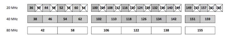
The selection of the 20MHz primary channel needs to be considered to minimize same-channel adjacent APs. In addition to this, try to avoid 20MHz secondary channel.
As shown in Figure 18 below, the channels with X mark are 20MHz secondary channels. For example, a user AP1 (channel bandwidth 80MHz) selects the 20MHz primary channel as CH36, and another neighbor AP2 (channel bandwidth 80MHz) 20M primary selects CH40. At this time, according to the 802.11ac available bandwidth detection rule, two APs cannot exclusively use the 40MHz channel bandwidth.
Of course, if everyone uses only 20MHz bandwidth, there is no such limitation, and all 5G channels in the GWN webUI list can be selected. Therefore, when in high-density deployment, sometimes using a 20MHz channel bandwidth may be better options for increasing the efficient channel multiplexing and reducing co-channel interference.
11. Recommended 5G channel bandwidth selection in different scenarios:
- 20MHz channel bandwidth: high-density areas, such as large stadiums, large event gatherings, urban hotspots where many WLAN networks are deployed;
- 40MHz channel bandwidth: normal-density area, such as large building office area;
- 80MHz channel bandwidth: low-density areas, such as small building areas, and areas with less WLAN deployment;
- 160MHz channel bandwidth: single AP area with small coverage, such as at home.