
OVERVIEW
Hotel WLAN
With the advantages of high-bandwidth, low-cost, and roaming benefit, WLAN can effectively offload cellular network in high user density area and bring a better user experience to customers. However, many of the current hotel WLAN deployments are lack of good planning, so that it can’t provide good coverage, clear signal and reliable speed to guest rooms.
Hotel Room High Speed WLAN Requirements
The competition in the hotel industry has transitioned from an era of competing hardware to software. It’s very important to improve customer dwelling satisfaction by high-speed wireless network coverage in guest rooms, and meeting customer needs for office work, or online entertainment. Therefore, the wireless availability, stability, and speed become the criteria for customer’s satisfaction rating. Especially for business customer, their demand for commercial quality of office network is particularly strict, and it’s hard to fulfill without a decent WLAN deployment planning. An excellent overall wireless internet experience requires certain hardware investment. But only by a good deployment and management, hardware can realize its value.
Challenges of Hotel WLAN Deployments
Longer construction period and high cost
The wireless network seems to be able to get rid of the shackles of the wired network, giving the terminal greater flexibility in use, but the access point AP still needs to rely on the wired network for connectivity and data transmission. According to the traditional deployment method of wireless products, after the location of the AP access point is selected in the hotel room area, it is necessary to run the CAT5 cable to the designated location. Construction cannot be performed while guest already checked in. In addition, if an access point AP is placed in a guest room, must be drill a wall hole through it. Therefore, it will lead to longer construction periods and increase the network deployment costs.
Signal instability and slowness
Many hotels still use access point APs in the 2.4G band, and the 2.4GHz band is an open band. There are many devices working in this band, such as: microwave ovens, Bluetooth, wireless phone, external APs, surveillance cameras, etc., It will cause a lot of interference to Wi-Fi devices and there are only 3 channels (Chanel 1 / 6/11) in 2.4GHz, which makes channel reuse difficult.
In addition, in order to save costs, access point AP equipment is often placed in the corridor area of the guest room, relying on the wireless signal through the wall to cover the interior of the guest room, while the wireless signal into the interior of the guest room is often not strong, affecting the network experience of the client terminal.
HOTEL ROOM WLAN COVERAGE SOLUTION
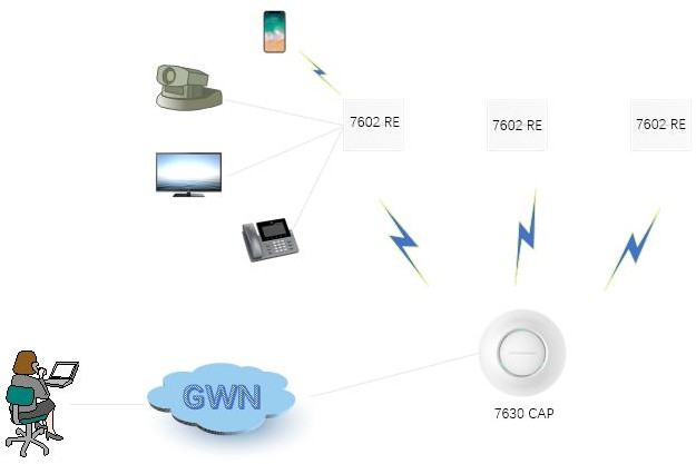
Grandstream’s hotel room wireless coverage solution includes two different role types of access points APs, named CAP and RE.
CAP(Central AP)
The CAP requires to access the wired network, connects wirelessly with the RE and responsible for data transmission. All GWN76XX (except GWN7602) access point APs can act as CAP.
GWN7630 is suitable for high-density scenarios or as the central access point CAP for hotel room coverage which providing high-performance and stable network access services.
RE(Range Extender)
The RE only connects to the CAP wirelessly, and can be used quickly after power-on, thus effectively extending the wireless network coverage of CAP. GWN7602 is very suitable to act as RE. It can not only provide the wireless coverage function of ordinary access points, but GWN7602 itself also contains a PSE Port, a Gigabit POE/POE+ Port, and two Ethernet Ports. After the RE wireless successfully connected to a CAP, the wired port can provide network service to different types of end devices, such as Grandstream IP phones, surveillance and PCs. Therefore, GWN7602 can be specifically used for wireless access in hotel and individual wireless coverage in room. In addition, it can also be used in SMB, coffee shop, and hospital or clinic which require both wired and wireless devices connection.
Wireless Product Parameters
The following example uses GWN7630 as the CAP and GWN7602 as the RE:
|
Parameter |
GWN7630 |
GWN7602 |
|
Product Picture |
 |
 |
|
Environment |
Indoor |
Indoor |
|
Simultaneous Dual- Band |
Yes |
Yes |
|
2.4 GHz Radio Rate |
600Mbps |
300Mbps |
|
2.4 GHz MIMO |
4 x 4 |
2 x 2 |
|
5 GHz Radio Rate |
1.7Gbps |
866Mbps |
|
5 GHz MIMO |
4 x 4 |
2 x 2 |
| Antenna Gain (2.4G./5G) |
4dBi/5dBi |
ANT1: 3dBi/3.5dBi ANT2: 3.5dBi/3dBi |
|
Concurrent Wi-Fi client |
200+ |
80 |
Wireless Access Layer Networking
In order to meet the need of hotels which is building a high-speed, stable, secure, easy-to-manage, and multi-service access wireless network, combined with the technical features of Grandstream products, the wireless access layer is recommended to network according to the “CAP + RE” topology.
At the same time, CAP and RE can be unified access management through GWN Cloud or local management to meet the requirement of different types of users.
Access Performance Evaluation
As mentioned above, the topology of “CAP+RE” is very suitable for the wireless coverage of hotel rooms. How about its access performance? The following test was conducted with a test site like the structure of a common business hotel room.
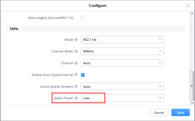
In this test, the power level of CAP and RE is “Low”, and the 5G channel bandwidth is VHT40 (see section “2.4 Channel and power planning” for details). In addition, the test terminal is iPhone 7 or Grandstream WP850, the throughput test software is IxChariot 6.7.
RE performance and coverage test
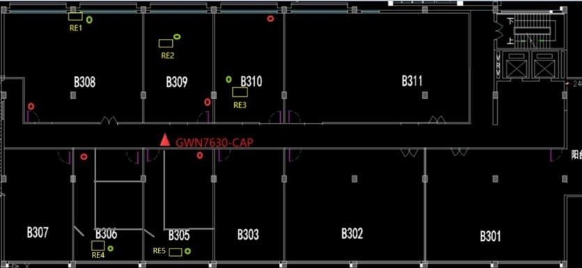
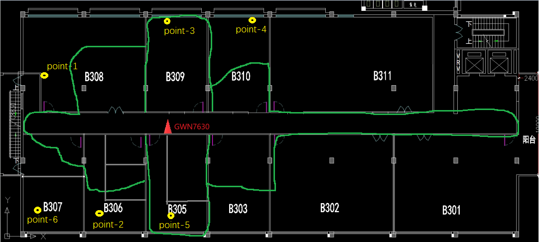
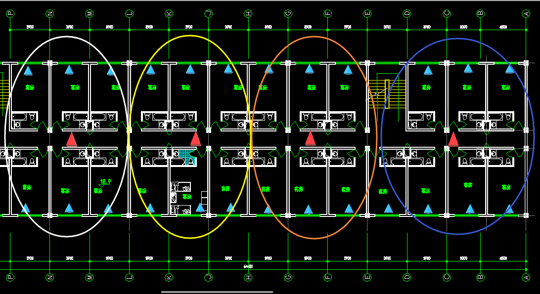
As shown in below figure, the CAP role is assumed by GWN7630, and the RE role is assumed by GWN7602. The CAP is placed in the corridor, and 5 REs are placed in rooms in different sizes and partitions.
In this region, the wireless environment of 5G frequency band is relatively good, and there are many interference devices in the 2.4G band, which have the influence on the test results. Therefore, the performance indicators of 5G are mainly tested.
The position of RE is shown in the yellow box in figure 2 below. The green dots represent “STA’s best point “and the red dots represents “STA’s worst point”. Both represent RE’s performance evaluation of the best point and worst point in the room.
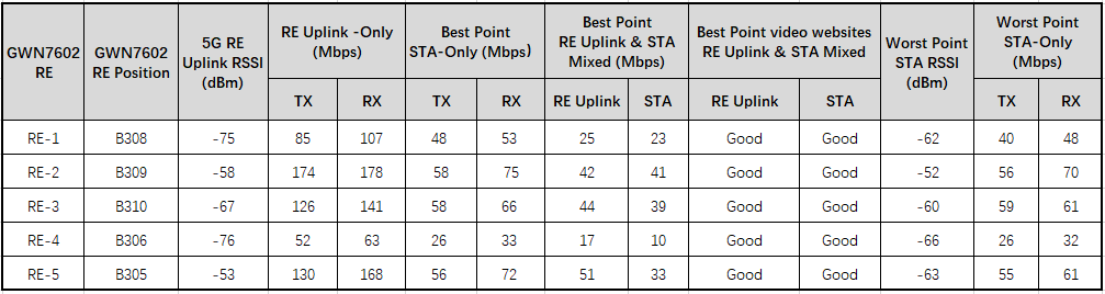
RE Uplink: Represents RE uplink, and the corresponding data in the table include uplink link throughput data and uplink video browsing effect data;
Uplink RSSI: Represents the RSSI corresponding to RE;
RE Uplink-Only: Indicates that wired PC1 is connected to the RE Gigabit port, and PC2 hosts on hotel backbone network. Only the throughput performance test between PC1 and PC2 (STA does not participate, the same below), TX means sending from CAP, RX means receiving from CAP;
STA-Only: Similarly, only the STA performs the throughput test. For convenience of understanding, TX means RE STA, and RX means STA RE.
RE Uplink & STA Mixed: Represents concurrent throughput testing between PC1 and PC2, and between STA and RE;
Video Websites: PC1 and STA browse videos on the video website (APP) at the same time;
It can be seen from the performance test above that the indoor coverage of RE is good for general hotel, Compared with the direct AP through-wall coverage, STA direct reception, the RE reception performance and coverage performance are more stable, If client meet the connection or performance issues, client can improve by increasing the power level of the RE or further reducing it to 20Mhz bandwidth (For hotel room coverage, under the premise of a small number of users, the 20Mhz bandwidth can fully meet the needs of users, see the section “2.4 Channel and power planning” for details).
CAP direct wall- through coverage test
Compared with RE room coverage, CAP direct wall- through coverage is the general hotel room coverage circumstance. Test 2 result can be compared with test 1.
CAP GWN7630 turns on the single frequency 5G SSID and tests the RSSI and throughput of the worst point in each partitioned room (the worst point refers to the farthest point in the room where the CAP is located).
Since 95% of wireless transmissions require to pass through walls, the RSSI and uplink and downlink throughput of the worst point of receiving CAP signals in each room are shown in the following table:
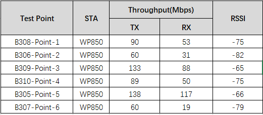
It can be seen from the table that the worst point RSSI is much lower than the test 1 result, which is basically around -80dBm. In this test area, although the worst point throughput can also be used, RSSI is not as stable as Test 1 (the signal-to-noise ratio of some test points is not guaranteed, and the signal-to-noise ratio is a guarantee of throughput performance). In addition, the uplink performance of RE in Test 1 can also be adjusted separately, which is incomparable to the direct coverage mode of CAP in Test 2.
If device cut at a threshold of -70dBm (the signal-to-noise ratio is guaranteed to be 25dB), as shown in the green line range. The business inside the green line can be basically guaranteed by the signal-to-noise ratio, and the areas outside the green line can only rely on the environment at the time. GWN7630-CAP can be used as a backup connection when the RE failure or offline, providing users with wireless terminal network access.
RE direct wall- through coverage test
The initial association of the STA is generally to select the AP with the strongest RSSI (for example, RE in this room), but it is not excluded that the client selects the RE in the next room or this room RE is offline, which causes the client to connect to the RE in the next room.
In this test 3, three different REs (placed in B309, B310, and B305 respectively) are used. After penetrating different types and quantities of media, the RSSI and wireless terminal throughput performance at points a and b of room B308.
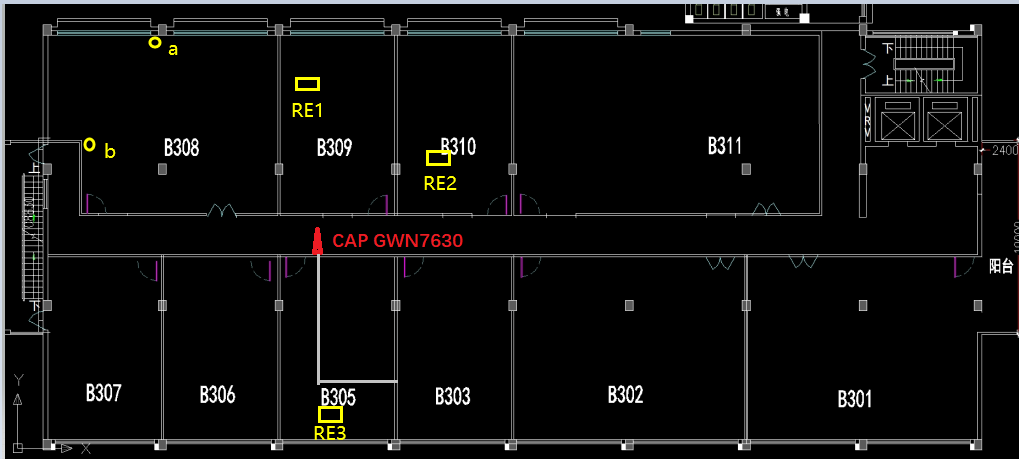
In below table we can notice the following:
RE in B309, after signal penetrating a wall, at point a, RSSI = -67dBm, throughput is 30-40Mbps; at point b, RSSI = -79dBm, throughput is 20-30Mbps;
The room B308 is larger than other, point b is located at the edge of B308. The RSSI has been reduced to
-79dBm, after the wireless signal penetration of the wall, the influence of the room area on the free space attenuation of the signal cannot be ignored;
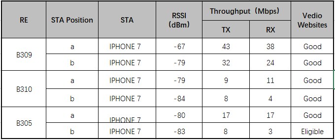
Therefore, after the signal penetrate a wall, the room size of an ordinary hotel (40-50 square meters), both of RSSI and throughput have redundant and easy to ensure; And the use effect of the guest room with too large area, which require to combine wireless environment to consider comprehensively.
The wireless environment in this test area is relatively good. The RSSI and throughput at point a are both redundant, while the RSSI at point b is not redundant, but the throughput is somewhat redundant.
RE in B310 and RE in B305 which penetrate more media (more than 2 walls), although in this environment, they can still be used, but both RSSI and capacity lack certain redundancy, so such connections need to be avoided as far as possible. However, under general circumstances, in the RE coverage mode of this room, the client RSSI is about -60 ~ -40dbm, and the probability of an STA incorrectly connecting to the next room is much small. If the RE fails offline, devices can also rely on Test 2 CAP backups are overwritten to avoid as much as possible.
CHANNEL & POWER PLANNING
Based on the technical characteristics of the “CAP + RE” solution, the mesh link channel between the CAP and RE requires to be consistent with the service channel. Therefore, channel and power planning are particularly important. Take 5G as an example of Mesh link: ![]() 7630 CAP
7630 CAP ![]() 7602 RE
7602 RE
According to the location layout of the rooms below, user can use one CAP to connect REs in 6 rooms at the same time. User only requires powering on the 7602 REs in each room, the 7630 CAP requires to connect to a ethernet network cable which support POE.
In the figure below, each circle represents a CAP driving 6RE, and 4 groups of “CAP+6RE” are used for 25 rooms.
RE layout considerations
- It is not recommended that CAP connect more RE, because the CAP and RE are still connected by 5G wireless link. If CAP connects more RE, it is certain that the 5G link of the farthest end of RE needs to cross more walls diagonally to complete the connection with CAP, so the wireless signal attenuation is too large, and the performance of wireless link connection is not guaranteed;
- In principle, the closer RE is to CAP, the better performance will be. If the optimal position of RE cannot be met, at least the RE should be placed in a prominent position on guest’s desk in the room, so that the RE can receive the wireless signal of the CAP, and it is also convenient for the guest to use the LAN of the RE port for the wired internet connection and wired telephone connection; placing RE in a hidden position for the sake of beauty will not be beneficial to RE signal reception;
- This solution is suitable for general hotel rooms. The room area is better not too large (it should not exceed 50 square meters). If a five-star or super five-star hotel, the suite itself has a large area, and there are many partitions or walls in the function area. Such hotel suites need to be tested and evaluated to determine whether this solution can be used, If necessary, direct coverage with wired AP is also required to ensure the effect.
Channel power planning
As shown in previous figure 9 above, in fact dense room layouts will lead to dense RE layouts so it is very important to control the power level of RE in each room. If REs is deployed according to the default “High” power level, many REs online will lead to increased wireless floor noise, which will affect the data analysis of terminal and AP, and wireless energy is also wasted.
After simulation tests, when the hotel’s wireless environment is not complicated and the 2.4G / 5G initial power of the RE is Low, the downlink signal of the RE penetrates two walls and then passes through certain free space signal attenuation. The wireless signal level can be controlled around -80dBm. Meanwhile, the connection between RE and CAP can also be completed to ensure business performance.
Therefore, it is recommended that the initial power levels of CAP and RE be set to “Low”, do not increase the power level arbitrarily to increase the noise floor in the area. If you encounter special circumstances, such as the room where an individual RE is located, the RE receiving the CAP signal is poorly, or the hotel room wall is very thick, which causes the RE to receive the CAP signal poorly. Client can appropriately increase the power level of the CAP or individual RE to Medium or even High.
In conclusion, the Low power level can be able to adapt to with many common scenarios, and the initial power level of local RE or CAP requires to be determined after simulation test for special scenarios.
Channel frequency and bandwidth planning
In addition to the importance of the transmit power level, the choice of channel frequency and bandwidth is equally important. It is also the same as in Figure 7 above. As mentioned earlier, the mesh connection uses 5G, the CAP and the 6 REs connected to the CAP use the same 5G frequency band, at this time, the 5G of the 7 APs share the same channel resources. If it is expanded to 4 groups and total of 28 APs, all CAPs can listen to each other due to the tunnel effect. If we consider the signal penetration between different floors and improper channel allocation, it will lead to a large number of conflicts.
Therefore, 2.4G requires 4 frequency points to be reused, and 5G requires 4 or 9 frequency points to be reused in order to minimize the impact of this problem.
It is recommended that the frequency band used by 2.4G is not limited to CH1/6/11, but four frequency bands of CH1/5/9/13 (the selection of frequency still requires to comply with local regulations).
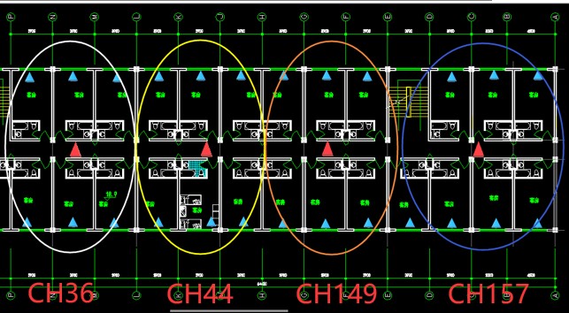
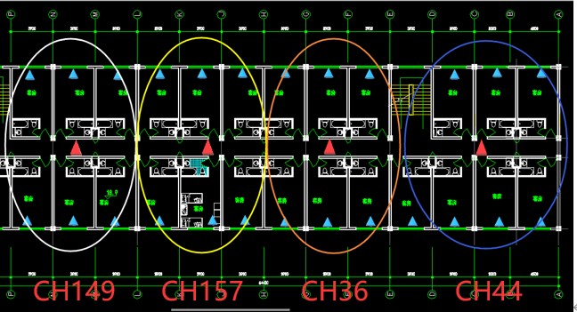
Regarding to the frequency bands of 5G, the redundancy is relatively large. It is suggested that both CAP and RE use the bandwidth of VHT40, instead of VHT80.The use frequency bands are CH36/CH44/CH149/CH157.
If the room size is much large and the number of single-story rooms is much large, we can even use the VHT20 bandwidth, so there are 9 multiplex frequency bands, which are CH36/40/44/48, CH149/ 153/157/161/165.
Consider the impact between the current floor and the upper and lower floors, we could use direct signal attenuation and oblique attenuation, for example (take 5G as an example, 2.4G is similar). After the frequency is planned for 2 floors, the more vertical floors that the floor needs to penetrate, the greater the signal transparency, the lower power used by the CAP or RE (power level: Low), this is exactly what we hope to achieve. The cast-in-place steel and cement between the floors are more effective for wireless signal attenuation, and the frequency planning can be completely reused after the adjacent floors are 2 or more than 2 floors.
Examples of frequency planning
The below figures show 3F and 4F frequency point planning examples:
Deployment and Use of SSID
Due to the mesh scenario, the number of SSIDs used is limited (generally less than 5). The 2.4G frequency band has a lot of interference and the 5G frequency resources are relatively abundant. Therefore, it is recommended to distinguish single frequency SSIDs (single frequency 2.4G and single frequency 5G) during deployment to facilitate customers’ rapid identification and access. Both CAP and RE can use the same SSID.