
The GWN76xx Wireless Access Points Series can be deployed in a network environment as standalone (using only one GWN76xx to provide wireless network access) or in Master/Slave architecture (using multiple GWN76xx units) to extend wireless network access range.
In Master/Slave configuration, a unique/chosen GWN76xx acts as master/controller and can manage up to 50 other GWN76XX as a slaves.
This guide covers Master/Slave architecture mode giving steps to successfully configure GWN76xx access points in your network environment; including steps to discover and pair GWN76xx units, create and manage SSIDs.
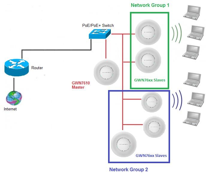
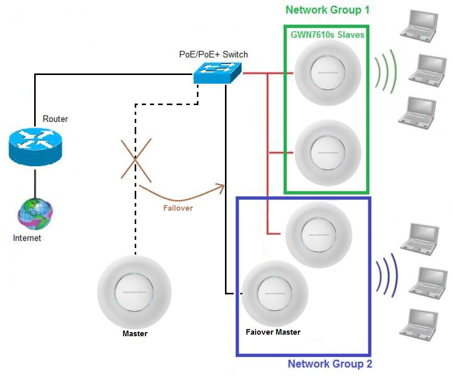
The figure below shows a sample setup of a GWN7610 master with different slave units, and connected Wi-Fi clients through different SSIDs.
DISCOVER AND PAIR GWN76XX ACCESS POINTS
In this guide, we will consider an environment where different GWN76xx access points models are installed, one of them will be Master over the remaining ones (Slaves) as shown in Figure 1.
To set a GWN76xx as Master, we need to access to its web interface by discovering it first on the network.
The following chapter describes two methods how to discover a GWN76xx connected to network and configure it as Master.
Discover GWN76xx
Once the GWN76xx is powered up and connected to the network correctly, it can be discovered using one of the following methods:
Method 1: Discover GWN76xx using its MAC address
- Locate the MAC address on the MAC tag of the unit, which is on the underside of the device, or on the package.
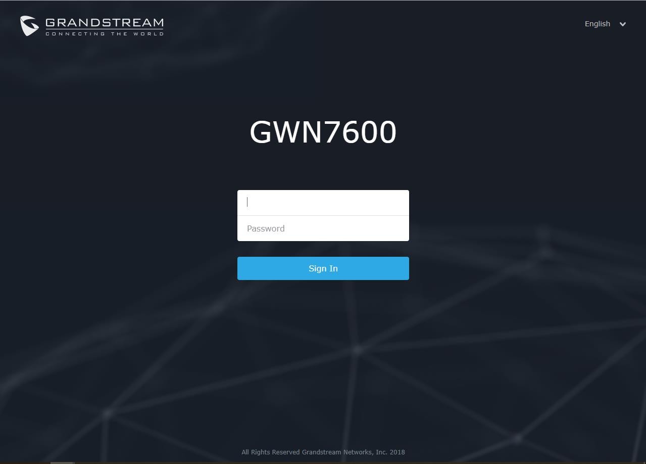
- From a computer connected to same network as the GWN76xx, type in the following address https://gwn_[MAC_address].local/ using the GWN76xx’s MAC address on your browser.
For example, if a GWN7610 has the MAC address 00:0B:82:8B:4E:28, this unit can be accessed by typing https://gwn_000b828b4e28.local/ on the browser.
Method 2: Discover GWN76xx using GWN Discovery Tool
- Download and install GWN Discovery Tool from the following link: http://www.grandstream.com/sites/default/files/Resources/GWNDiscoveryTool.zip
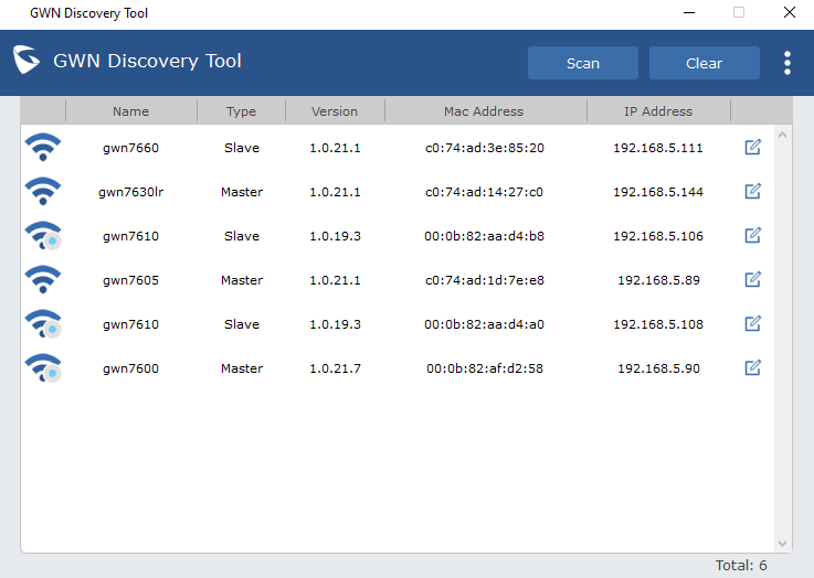
- Open the “GWN Discovery Tool”, click on Select to define the network interface, then click on Scan.
- The tool will discover all GWN76xx Access Points models connected on the network showing their MAC, IP addresses and firmware version.
- Click on Manage Device to be redirected directly to the GWN76xx’s configuration interface, or type in manually the displayed IP address on your browser.
Notes:
Pair Slave GWN76xx Access Points
To pair a GWN76xx access points (slaves) connected to the same network as the Master GWN76xx follow the below steps:
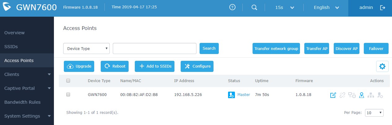
- Connect to the GWN76xx Web GUI as Master and go to Access Points.
-
Click on
 button in order to discover different GWN76xx access points models within GWN76xx’s Network, the following page will appear.
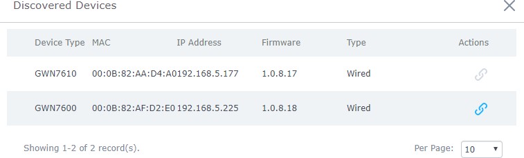
- Click on Pair
 under Actions, to pair the discovered Access Point as Slave with the GWN76xx acting as Master.
 - The paired GWN76xx will appear Online, click on
 to unpair it.

- Click on next to Master or paired access point to check device configuration for its status, clients connected to it and configuration. Refer to below table for Device Configuration tabs.
Field | Description |
Status | Shows the device’s status information such as MAC, Product Model, Part Number, Boot Version, Firmware version, IP Address, Link Speed, Uptime, and Users count via different Radio channels. |
Clients | Shows the connected users to the GWN76XX access point. |
Configuration |
|
Table 1: Device Configuration
Note: If a GWN76xx is not being paired or pair icon is grayed, make sure that it is not already paired with another GWN76xx Master Access Point. If yes, it needs to be unpaired first, or reset to factory default settings in order to make it available for pairing by other GWN76xx Access Point Controller.
Configure Failover Master
Failover Master Overview
For redundancy and backup function, the GWN76XX access points are now supporting Failover Master function, users can specify a slave AP as failover master. Whenever it detects the master is down, it will promote itself to be as failover master.
In order to avoid a single point of failure in a wireless network, and for redundancy and failover function, users are able to configure a slave AP as failover master, this slave AP will be the replacing the Master in its functions, and will promote itself as failover master within a time frame of around 20~30 minutes by entering failover mode, after then, if the master AP comes back, failover master will automatically go back to slave mode.
The Failover architecture is as follow:
Set a Failover Master
Users can select the failover Master by following below steps:
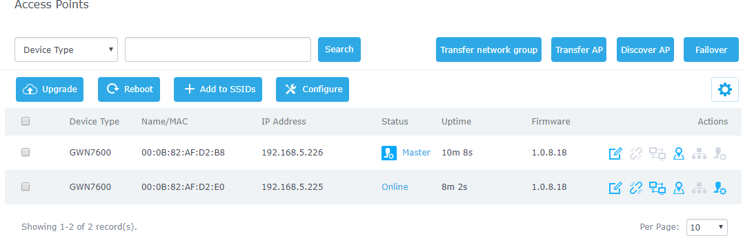
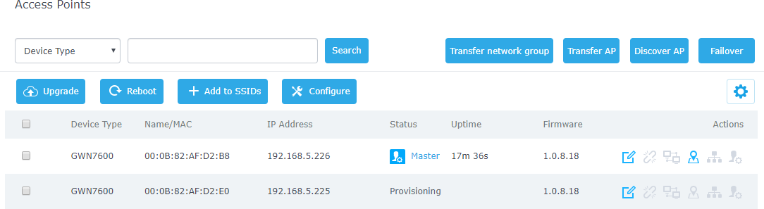
- Log into web GUI of the master GWN, and go to Access Points, then click on Failover as follow:
- Once Failover is pressed, following window will pop up, set one AP as Failover by selecting its MAC Address:
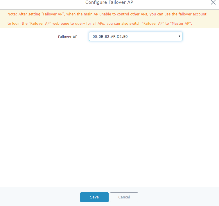
- Press Save then Apply Changes.
Once the Failover master is selected, the Master will provision the selected AP with the needed network configuration as illustrated in the following screenshot:
When done, the selected AP status will change to ONLINE, this AP will keep monitoring the Master and will be promoted as Failover when the primary Master is no more responding.
Failover Mode
As explained previously, once failover slave has been selected, the primary master will send the configuration of the network to the failover slave, and the slave will start monitoring the status of the primary master to detect any failure for any reason (network connection loss, power outage).
In case of failure, the failover slave will promote itself to a temporary backup master while waiting for the primary master to recover.
During the failover mode, users could access the web GUI of the failover slave using a special failover account with same admin password.
- Username = failover
- Password = admin password
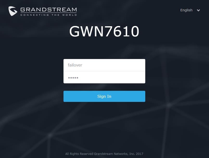
Once done, users will have access to the AP in Failover mode as displayed in the following screenshot:
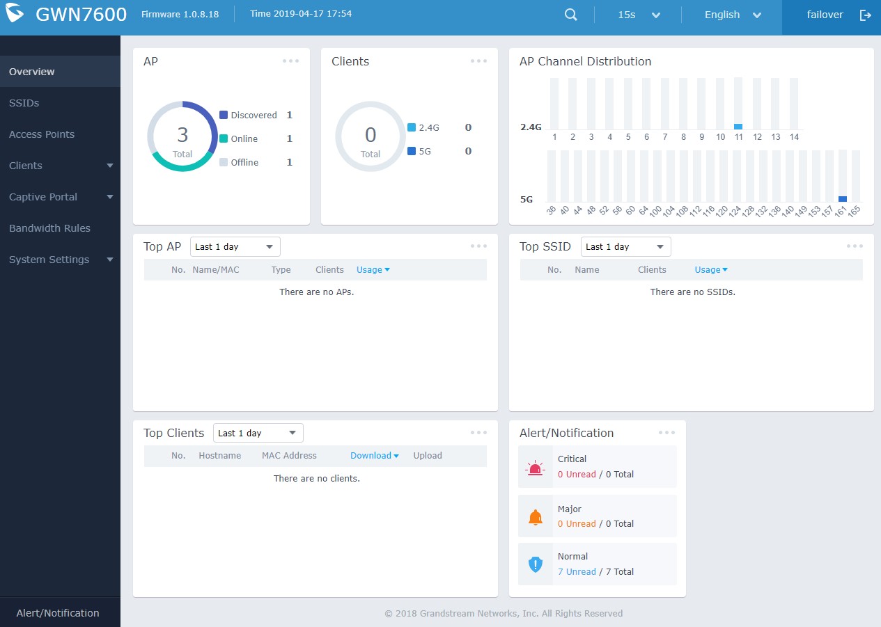
The failover mode has only read permission on the configuration and very limited options, users still can reboot other slave Access points in case it is needed.
At this stage, the AP will keep monitoring the primary Master, and will automatically go back to slave mode when it detects the recovery of the primary Master.
The AP is now in Failover mode, and it’s acting as the primary Master, this can be illustrated in the AP status when accessing Access Points board, a new option “Switch to master” will be added to the board in the top right corner:
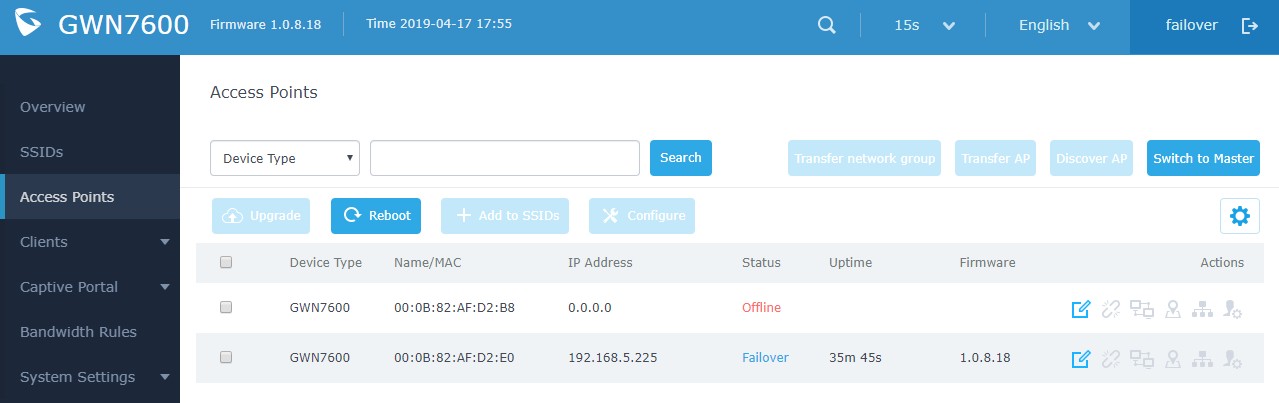
The new added button “Switch to master” allows users to set the failover slave as the new primary master of the wireless network, once this is done they have full write permission control over the web GUI option as usual.
Note: When the user presses the “Switch to master” button, the AP will be set as Master, and will not be able to return to the slave mode automatically, users can set this option when the primary Master is no longer responding. A confirmation message will pop up when the user presses this button:

Once the user confirms and presses OK, the AP will be a Master access point, and users can configure then any option including a new Failover Master:

Notes:
- Once this is done the Failover Slave will have full write permission control over the web GUI option as usual. Use that button to switch to master and takeover the rest of the APs.
- If you click « Switch to Master », this would be become a non-revertible behavior. Failover Slave will become actual master and the prior master can’t take back the control anymore.
- When Failover Slave is switched to Master, you will use the Prior Master AP credentials: username: admin, and the admin password.
- Otherwise, when original master comes back online, then Failover Slave will become slave again to prior original Master.