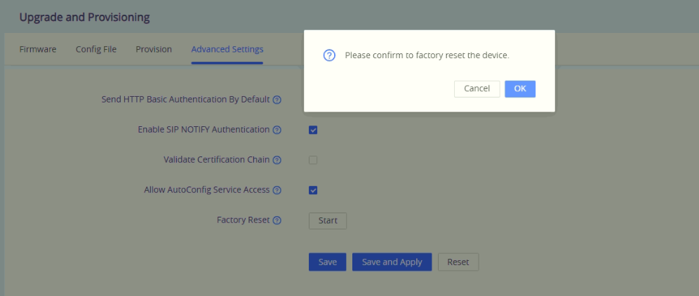
The GSC3518HS is a high-definition multicast talk-back horn speaker that allows public spaces, large offices, school playgrounds, hospitals, parks, and more verticals to build powerful outdoor announcement solutions that expand security and communication. This robust SIP speaker offers crystal clear HD audio functionality with a high-fidelity 50-Watt speaker and supports IP66 dust and water resistance. The stainless steel packaging is sturdy and durable, and can be used in extreme weather conditions. The GSC3518HS supports PoE++ input and PoE+ output, catering to another device cascading scenarios. Users can easily sculpt a state-of-the-art security and PA announcement solution. Thanks to its modern industrial design and rich features, the GSC3518HS is an ideal SIP talk-back horn speaker for any setting.
PRODUCT OVERVIEW
Feature Highlights
The following table contains the major features of the GSC3518HS:
GSC3518HS
High-power 50W speaker output delivering loud, clear audio for both indoor and outdoor environments.
Supports up to 16 configurable SIP Accounts
Configurable SRTP/TLS encryption ensuring secure and reliable voice transmission.
Industrial-grade design (IP66) for weather-resistant installation in diverse environments.
Integrated 10/100Mbps Ethernet port with PoE for simplified power and network connectivity.
Support for differential LINE IN and LINE OUT connections
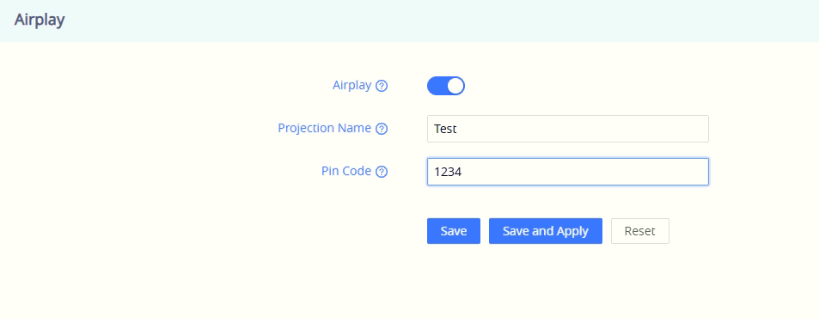
Support for Airplay, ONVIF RTSP/HTTP Streaming, local audio files, and mibile app playback.
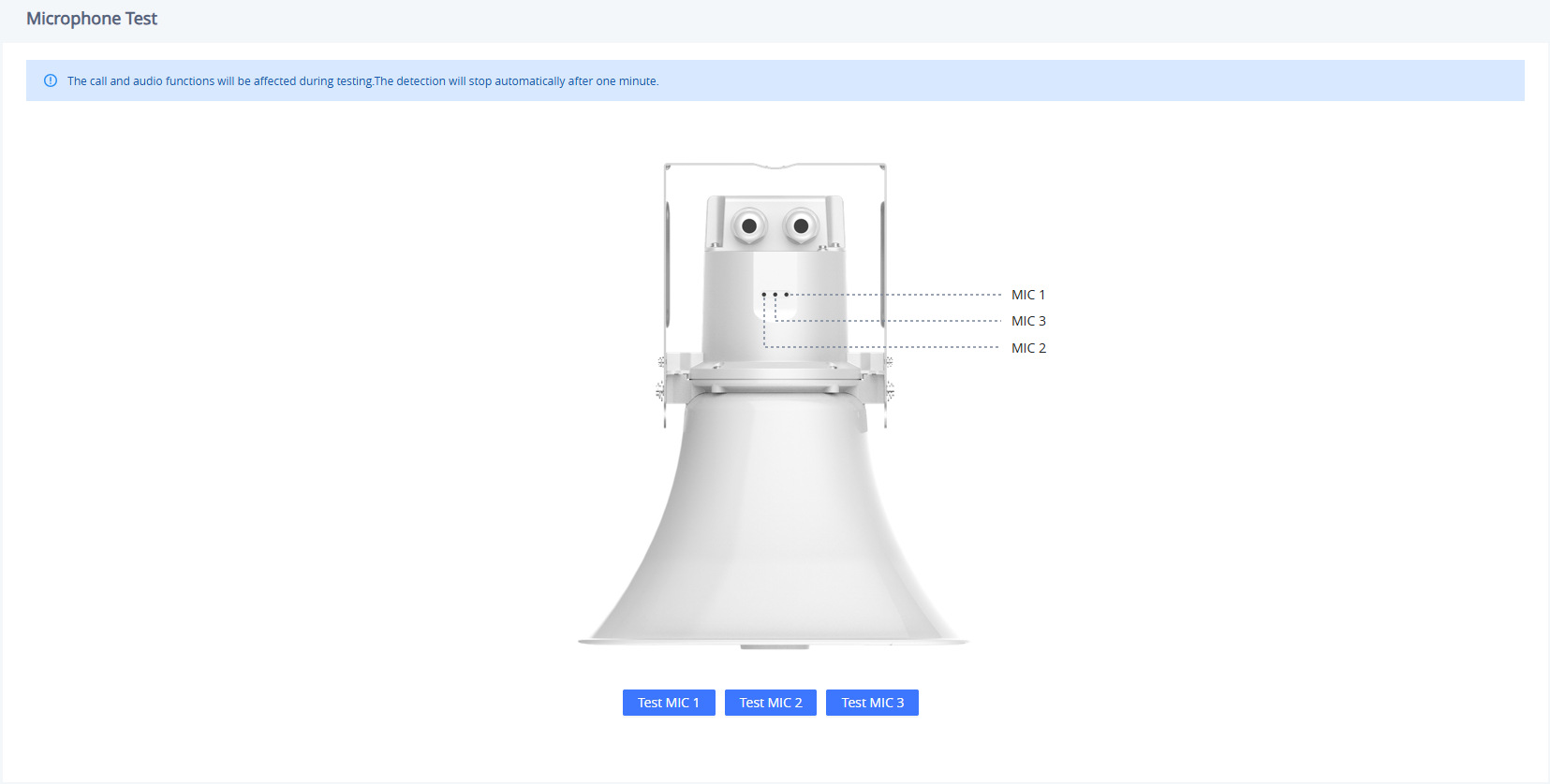
3 microphones supporting AI noise reduction
GSC3518HS Features in a Glance
GSC3518HS Technical Specifications
The following table summarizes all the technical specifications, including the protocols/standards supported, voice codecs, telephony features, languages, and upgrade/provisioning settings for GSC3518HS.
User and administrator level passwords, MOS and MDS-sess based authentication, 256-bit AES encrypted configuration file, TLS, SRTP, HTTPS, 802.1x media access control, secure boot
Multi-language
English, German, French, Spanish, Portuguese, Russian & Chinese
Upgrade/Provisioning
Firmware upgrade via TFTP / HTTP/ HTTPS or local HTTP upload, mass provisioning using GDMS/TR069 or AES encrypted XML configuration file
Power & Green Energy Efficiency
POE++ Input, complies IEEE 802.3bt standard, Class 8, Max power 71 Watt
Max Input voltage 57V
POE+ Output, complies IEEE 802.3at standard, Class 4, Max power 25 Watt
DC IN 24V/4A – 48V/2A
Ingress Protection
IP66, waterproof cable gland
Installation Type
Wall Mount, Pole Mount
Temperature and Humidity
Operation: -30°C to +60°C
Storage: -40°C to +60°C,
Humidity: 10% to 90% Non-condensing
Package Content
GSC3518HS, mount kit, quick installation guide
Physical
Unit Dimensions: 285*205*325mm
Unit Weight: 2.87 kg, Box Weight: 3.913 kg
Compliance
FCC, IC, CE, RCM
GSC3518HS Technical Specifications
Package Content
Package Content
Label
Item
Quantity
Description
a
Speaker Main Unit
×1
Main GSC3518HS outdoor speaker body with adjustable mounting arm.
b
Junction Box Cover
×1
Protective housing for the rear cable connections.
c
Expansion Bolts
×4
Used for mounting the speaker bracket securely to a wall or ceiling.
d
Cable Glands
×2
Waterproof cable connectors to seal and protect input cables.
e
Mounting Screws
×3
PM 3 × 10 mm screws for securing the junction box cover.
f
Rubber Gaskets
×2
Replaceable seals used to maintain waterproof performance.
g
Backup Bolts
×2
M4 × 10 mm bolts for bracket adjustment and backup locking.
h
Quick Installation Guide
×1
Printed guide for installation steps.
i
Regulatory Paper
×1
Complete Regulatory information.
Back Cover Ports
The back panel of the GSC3518HS contains all primary wiring ports, grounding points, and mounting connections. Proper wiring and grounding are essential to ensure safety, waterproof sealing, and reliable performance.
Note
The PoE IN port provides PoE+ powering, while the PoE OUT port requires PoE+ powering.
Back Cover Ports
Main Connectors and Terminals
This section provides an overview of all physical ports and connection interfaces available on the GSC3518HS. It explains the purpose of each port, including network connectivity, power options, audio I/O, alarm integration, grounding, and safety mounting points. Use this reference to ensure proper wiring, installation, and device expansion in different deployment environments.
Port / Label
Description
PoE IN (LAN)
RJ45 network port supporting Power over Ethernet (PoE). Provides both data and power to the speaker through a PoE switch or injector (IEEE 802.3af/at/bt).
PoE OUT
RJ45 passthrough port used to supply PoE power and data to another device, such as an additional IP speaker or camera.
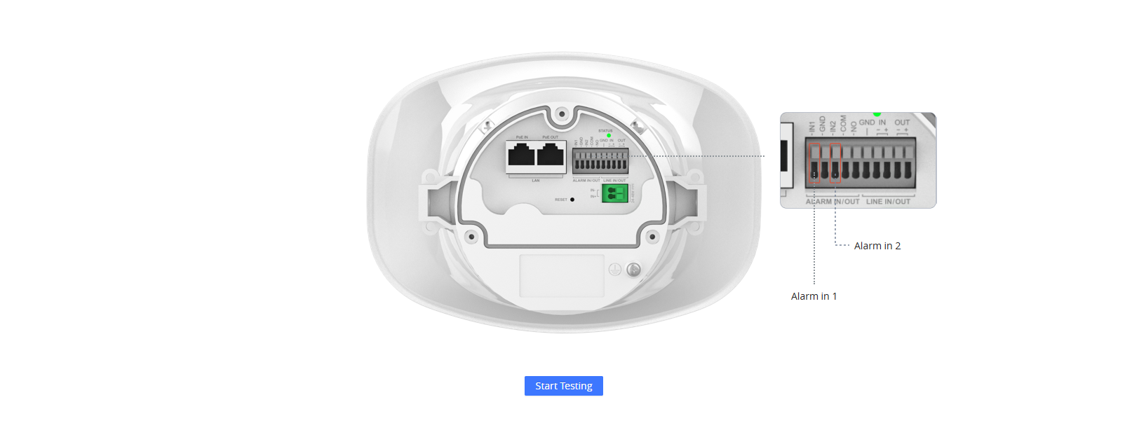
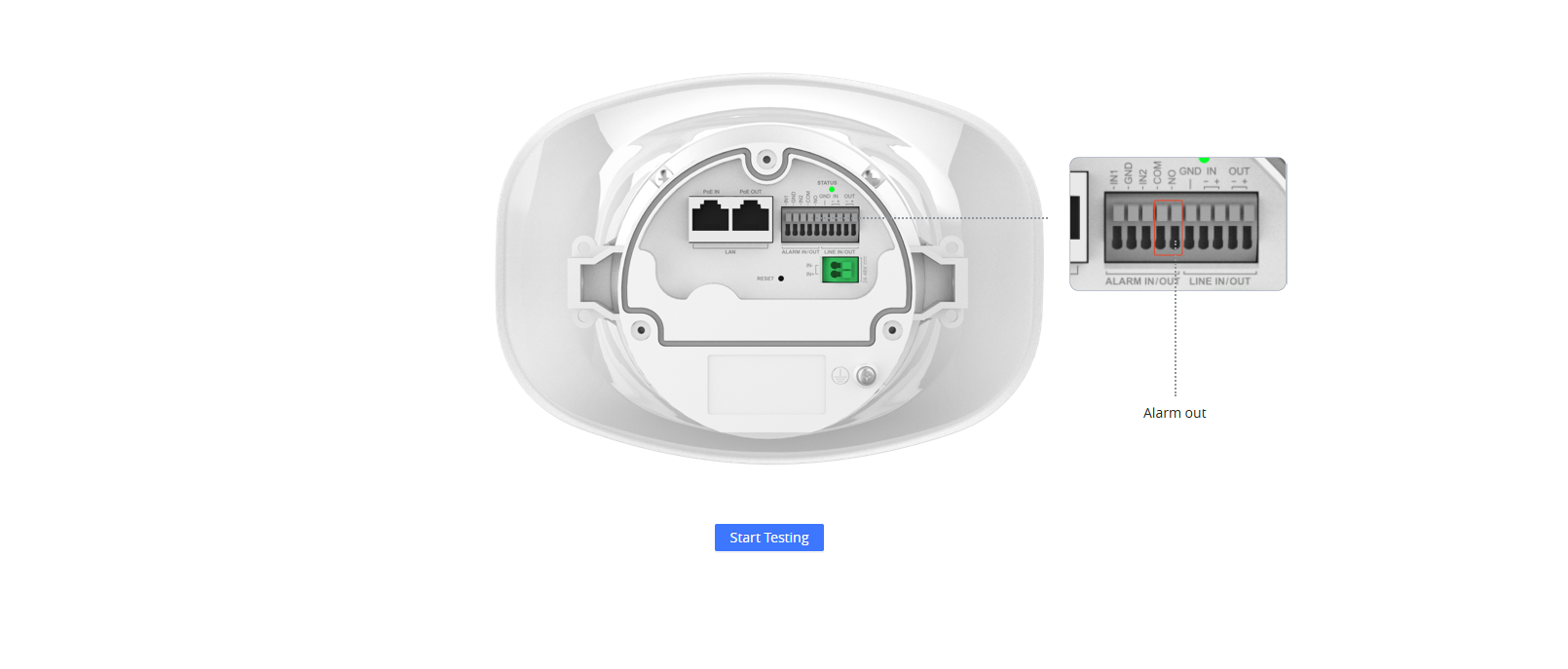
ALARM IN/OUT (IN1, IN2, GND, NO, COM)
Terminal block for external alarm integration. IN1/IN2 are digital inputs for sensors or triggers; GND is the common ground; NO/COM form a relay output for controlling external alarms or devices.
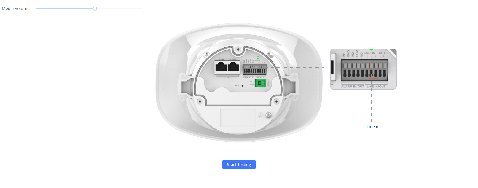
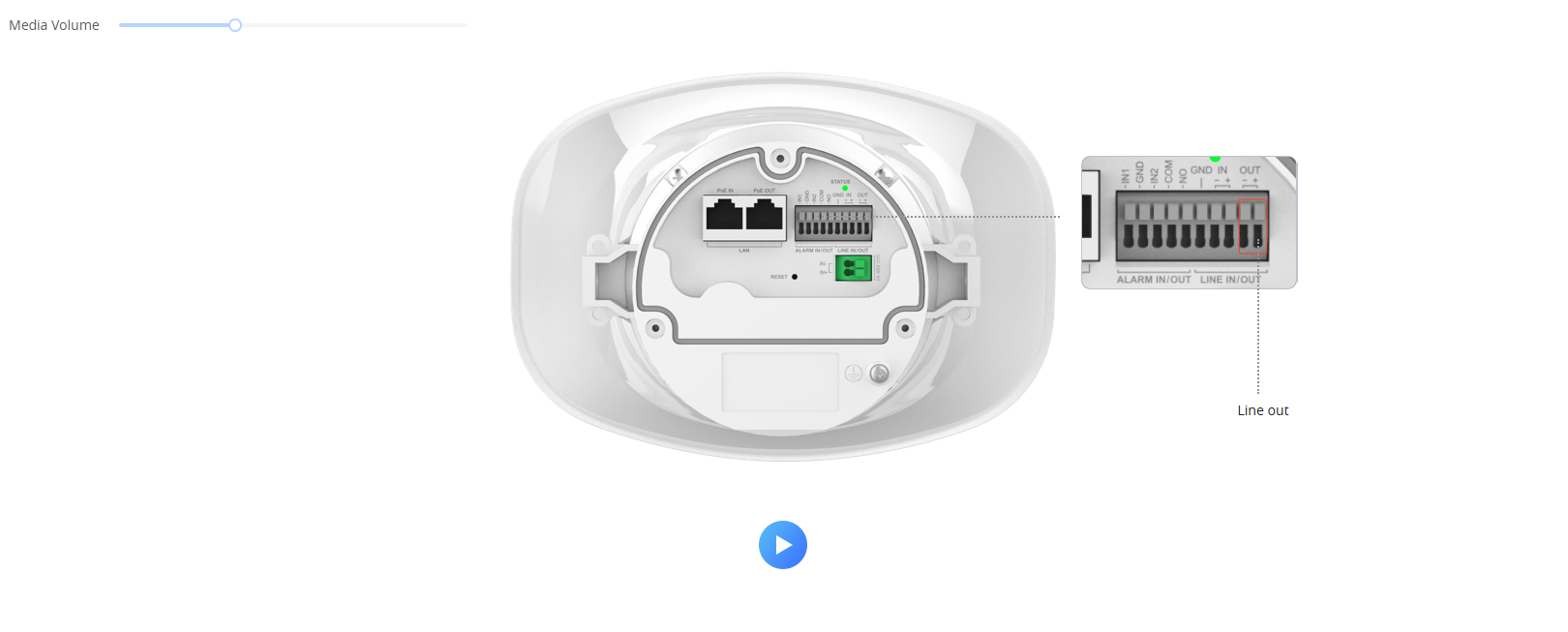
LINE IN/OUT (IN+/–, OUT+/–, GND)
Balanced audio input/output interface. Allows connection to external microphones, amplifiers, or powered speakers for extended audio coverage.
DC 24–48V
Power input terminal for direct DC power supply (24V–48V) when PoE is not used. Polarity-sensitive.
Ground Wire Terminal
Dedicated grounding point. Must be connected to an earth ground to prevent electrical surges or static damage.
Security Eyebolt
Anchor point for a safety cable or chain to prevent the device from falling if the mounting structure fails.
Anti-off Rope
Safety securing screw point used to temporarily hold the device during installation or maintenance.
MIC
Built-in microphone port for audio capture, monitoring, or two-way communication functions.
Notes
“Must Attach”: Both the security eyebolt and ground wire must be installed before powering on the device.
Use only the provided ground screw location; do not attach to any other internal screws.
Ensure the back cover is tightly sealed after wiring to preserve the waterproof IP rating.
Avoid pulling or twisting the Ethernet and alarm cables after connecting to prevent damage to the internal board.
Ceiling Mount
The GSC3518HS can be mounted on a ceiling or any flat overhead surface using the included expansion bolts. This method ensures a stable, downward-facing audio projection, ideal for wide outdoor areas.
Installation Steps
Mark the Drill Points
Use the bracket of the speaker (a) as a reference or follow the illustrated mounting pattern.
Mark three holes on the ceiling in the exact layout:
Horizontal spacing: 101 mm (3.98”)
Vertical spacing: 33 mm (1.30”)
Drill and Prepare the Mounting Surface
Drill holes at the marked positions.
Insert the expansion bolts (c) into each hole to secure the mounting base.
Attach the Speaker Bracket
Hold the speaker unit (a) with its bracket aligned to the drilled holes.
Fasten the bracket using the installed expansion bolts (c).
Ensure the bracket is fully tightened, and the speaker hangs securely.
Adjust Orientation
After mounting, slightly adjust the angle of the speaker to direct sound output as desired.
Make sure all bolts are firmly secured to prevent vibration or misalignment.
Pole Mount
The GSC3518HS can also be mounted onto a vertical or horizontal pole using metal straps (not included in the package). This installation method is ideal for outdoor environments such as parking lots, campuses, or street areas where wall mounting is not suitable.
Installation Steps
Prepare the Speaker Assembly
Use the speaker unit (a) with its attached mounting bracket.
Position the speaker bracket against the mounting pole.
Attach the Metal Straps
Insert two metal hose clamps or stainless steel straps (not included in the package) through the mounting slots on the bracket.
Wrap each strap tightly around the pole and fasten securely using a screwdriver or wrench.
Ensure both straps are parallel and firmly tightened to prevent movement.
Adjust the Speaker Orientation
Once attached, adjust the tilt or rotation of the speaker (a) for optimal sound direction.
Confirm that all fasteners are tight and the bracket does not slide along the pole.
Check Cable Routing
Guide all cables neatly through the mounting bracket to the back of the speaker.
Make sure cables are not twisted or pinched between the pole and the bracket.
Installing The Speaker Support
This step involves connecting the cable glands and securing the junction box cover before final tightening of the speaker’s bracket position. Proper sealing and bolt alignment ensure both waterproof integrity and stable speaker support.
Installation Steps
Connect the Cables
Insert all power, network, and audio cables through the cable glands (d).
Tighten the glands firmly to create a waterproof seal.
Connect the cables to their respective ports inside the back cover (refer to the connection layout in Section 2).
Attach the Junction Box Cover
Place the junction box cover (b) onto the back housing, aligning the screw holes.
Fasten it using the PM 3 × 10 mm screws (e) to secure the cover in place.
Make sure the cover sits evenly and that all cable glands are facing downward.
Replace Rubber Gaskets (if required)
If the rubber gaskets (f) are worn, replace them with the included spares.
Ensure the gasket surfaces are clean and fully pressed to maintain the waterproof seal.
Secure the Speaker Bracket Angle
Adjust the speaker’s tilt angle to the desired direction.
Use the M4 × 10 mm bolts (g) to tighten the side pivot points on both sides of the bracket.
Confirm both bolts are symmetrically tightened, and the angle is locked.
Final Check
Verify that the junction box cover (b) and cable glands (d) are fully tightened.
Ensure the speaker is stable, firmly mounted, and properly grounded.
The bracket must not be over-tilted; refer to the illustration for correct alignment.
Accessing the Configuration Interface
Connecting With MAC Address
A computer connected to the same network as the GSC3518HS can discover and access its configuration interface using its MAC address :
Locate the MAC address on the MAC tag of the unit, which is on the underside of the device, or on the package.
From a computer connected to the same network as the GSC3518HS, type in the following address using the GSC3518HS’s MAC address in your browser: http://gsc_<mac>.local
Example: if a GSC3518HS has the MAC address C0:74:AD:11:22:33, this unit can be accessed by typing http://gsc_c074ad112233.local on the browser.
Connecting Using GS Search
A computer connected to the same network as the GSC3518HS can launch the GS Search App, view the assigned IP address of the unit, then use that IP address in a local web browser to access the WebUI configuration Interface. Download the GS Search tool from the following link.
Example: the discovered IP address was : 192.168.6.15, the unit can be accessed by typing: http://192.168.6.15
GSC3518HS WebUI
GETTING STARTED
This chapter provides basic installation instructions, including the list of the packaging contents, and also information for obtaining the best performance with the GSC3518HS.
GSC3518HS DEPLOYMENT SCENARIOS
GSC3518HS SIP Multicom Intercom System
GSC3518HS can be used as an Intercom System using built-in SIP accounts. Once the SIP account is registered, the device can receive paging/intercom calls, and it will automatically answer calls coming from allowed numbers.
To register a SIP account on the GSC3518HS, the user needs to go under Account 🡪 Account N 🡪 General Settings, and enter the account information as below, then save and apply the configuration.
SIP Account Configuration
Once the account is registered correctly, the GSC3518HS will show the account status under Status 🡪 Account Status.
SIP Account Status
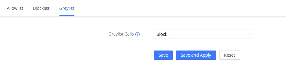
By default, the GSC3518HS Blocks non-allowed numbers under Calls → Blocklist/Allowlist/Greylist → Greylist. The user needs to either accept numbers that are not on the allowlist calls or set up an allowlist that contains the number that will be allowed to call the GSC3518HS.
Greylist Calls
As soon as a SIP call is received by the GSC3518HS, it first checks if the Caller ID number is allowed on the Allowlist and then answers automatically.
Notes
GSC3518HS is an intercom system and auto-answers all numbers on the Allowlist.
By default, GSC3518HS plays a Warning tone when auto-answering incoming calls. This warning tone can be disabled under Account 🡪 Account N 🡪 Call Settings, “Play Warning Tone for Auto Answer Intercom”.
Multicast Paging Application
Multicast paging is an approach to let different SIP users listen for paging calls from a common multicast IP address. In multicast page calls, an audio connection will be set up from sender to receiver, but the receiver will be able to receive audio, a one-way communication. The 2 entities, Sender/Receiver, must be located on the same LAN (same broadcast domain).
To receive a multicast page, GSC3518HS must be well configured to listen to the right address and port. The configuration is located under Device Settings → Multicast/Group Paging. Up to 10 listening addresses are supported with priority levels from 1 to 10.
Multicast Paging Listening Addresses
In the above screenshot, the Listening Address “237.11.10.11:6767” with the label “Sales” has the highest priority.
Users can enable the “Paging Priority Active” option (under the Multicast Paging tab) to accept incoming paging calls during active multicast paging. The paging call with a higher priority than the active one will be accepted.
Multicast Paging Paging Priority Active
In the case of receiving a multicast paging call while on a unicast SIP call, the GSC3518HS can choose to either keep the SIP call or hold the last and allow the multicast call, depending on the paging call priority.
This behavior is controlled by the “Paging Barge” option.
Paging Barge = Disabled During an active SIP call, incoming multicast paging calls are not dropped; they are queued. The device will automatically play the multicast page after the SIP call ends.
Paging Barge = Enabled with Priority If an incoming multicast page has a higher priority than the configured Paging Barge level, the SIP call will be placed on hold, and the multicast page will be played immediately.
Multicast Paging Priority Barge
Onvif Settings
The ONVIF (Open Network Video Interface Forum) feature allows the GSC3518HS to integrate seamlessly with third-party Video Management Systems (VMS), NVRs, or network surveillance platforms that support the ONVIF protocol. Through ONVIF, the Grandstream speaker can be discovered, authenticated, and controlled by compatible systems, and this enables functions such as audio broadcasting, event notification, and two-way communication over the network.
Using a VMS Software to Play Audio Files via ONVIF
In this example, a network administrator wants to use a VMS application (such as Milestone XProtect or Axxon VMS) to broadcast an audio file stored on the computer to the Grandstream GSC3518HS horn speaker.
On the GSC3518HS Web UI, navigate to System Settings→ ONVIF.
Enable ONVIF Function.
Set ONVIF Username:admin
Set ONVIF Password:admin
Click Save and Apply.
Onvif Settings
Open the VMS software on your computer.
Depending on your VMS software, go to the device management or discovery section.
Add a new ONVIF device and enter the IP address of the horn speaker.
Use the same ONVIF credentials (admin / admin) for authentication.
Once the connection is established, the speaker will appear as an ONVIF-compliant device.
You can now select it as an audio output endpoint.
Using an ONVIF client or VMS software that supports intercom/audio-out (for example, the Happytime ONVIF tool), you can select an audio file on the PC and play it, and the audio will be streamed to the GSC3518HS speaker. Other PC-based VMS solutions that support ONVIF audio-out can also be used to achieve the same function.
LINE OUT/IN PORTS
The Line In/Out ports let the GSC3518HS work with other audio equipment. Line In receives sound from sources like a microphone or music player, while Line Out sends the speaker’s audio to devices such as an amplifier or recording system, enabling flexible integration with larger sound setups.
On the Grandstream GSC3518HS horn speaker, both Line In and Line Out are analog audio interfaces, but they serve opposite purposes. Here’s a simple explanation with real use cases:
Line Out
Line Out
Purpose: Sends (outputs) audio from the horn speaker to another device.
Signal direction: From the GSC3518HS → external equipment.
Use case examples:
Connect the speaker to an external amplifier to drive larger speakers or a PA system in a big area.
Feed audio from the speaker to a recording or monitoring system, allowing security staff to listen to or record announcements.
Example: A warehouse uses several horn speakers connected to a central amplifier. The GSC3518HS sends its SIP paging audio through the Line Out port to the amplifier, which then broadcasts it to all zones.
Note
When wiring Line In/Out, make sure the GND (ground) pin is included in the connection. Testing showed audible noise when the Line In/Out signal was connected without the GND wire.
Line In
Line In
Purpose: Receives (inputs) audio from an external source.
Signal direction: From another device → GSC3518HS.
Use case examples:
Connect an external microphone for live announcements through the horn.
Connect a music player, intercom console, or paging system to feed background audio or messages into the horn speaker.
Example: A reception desk has a desktop microphone connected via Line In, allowing the receptionist to make live voice announcements through the GSC3518HS.
Configuring Alarm In / Alarm Out
The Alarm In/Out ports on the GSC3518HS allow the device to work with external sensors and systems for automated event handling, for example, triggering audio alerts or external alarms when specific conditions occur.
Alarm In (IN1 / IN2)
These ports receive input signals from external devices like motion sensors, door contacts, or panic buttons. When a sensor is triggered, the horn speaker can automatically perform actions such as playing a warning sound, making a SIP call, or activating the alarm output.
When a 5V–12V DC signal is applied, the speaker detects it as an active alarm, and when the signal stops, it returns to an inactive state. This allows the device to automatically react to events like a fire alarm, door sensor, or motion detector.
Alarm In
Configuration Overview
Configuration Overview
Sensor Type — “Always On” vs “Always Off”
Always On This means the sensor’s normal (idle) state is “open/disconnected.” When the alarm switch is triggered, the contact closes (connects), and that change is detected as the alarm event. This is the default mode and is typically used with sensors that stay open until triggered.
Always Off This means the sensor’s normal (idle) state is “closed/connected.” When the alarm switch is triggered, the contact opens (disconnects), and that change is detected as the alarm event. This mode is used with sensors that stay closed until triggered.
Cycle Time & Frequency: Used to schedule when the alarm monitoring is active, continuously, at specific times, or on certain days.
Linkage Function: These are the actions the device will automatically perform when the alarm input is triggered. At least one must be enabled.
Play Audio – The device plays a pre-recorded audio file or ringtone through its speaker when the alarm is triggered.
Make Call – The device places a call to a preset number or extension when the alarm is triggered. You can define up to two dialed numbers. In addition, you can define a call to 3rd party video stream by configuring the Call RTSP Video Source.
Linked Alarm Output – This triggers an external alarm output/relay, such as: siren, door relay…
Hang up – If the device is already on a call when the alarm is triggered, it will hang up that call automatically.
Example Scenarios
Panic Button (Emergency Call): A wall-mounted panic button triggers the Make Call function, instantly calling a preset SIP extension and playing a voice alert like “Emergency assistance required.”
Door Sensor (Access Alert): Connect a door magnetic contact to Alarm In 1. When the door opens, the GSC3518HS plays a short “Door Open” tone and flashes a linked strobe light.
Motion Detector (Security Mode): Attach a PIR sensor to Alarm In 2. When movement is detected after hours, the horn speaker automatically sounds a siren and calls the security control room.
Alarm Out
These ports send output signals to control other devices such as sirens, strobe lights, or access control systems. When the speaker detects an alarm condition (from Alarm In ), it can activate these connected devices through the relay output (NO / COM).
Example Scenarios
Example 1: When an alarm input is triggered, the GSC3518HS activates an external strobe light using the Alarm Out port.
Example 2: When an alarm is recieved for an emergency , the speaker uses Alarm Out to trigger a loud external siren.
GSC Assistant
GSC Assistant is a mobile client that works with the GSC series from Grandstream. It supports fast management and playback of GSC speaker products on your mobile device. It also features fast management of GSCs in the same LAN, quick positioning, convenient playback of a single GSC, custom partitioning of multiple GSCs, and unified playback for multiple zones. It also supports IPv4 and IPv6, and is compatible with complex network environments.
The GSC35xx Zone Music is a feature that facilitates effortless audio distribution among various speakers within a local network. It offers zone-specific playback control, empowering users to efficiently manage, group, and stream music to different locations from one interface, which is called the Zone Manager.
For more information on how to configure the music zone feature, please refer to the guide: GSC35xx Music Zone Guide.
Speech Synthesis
The Speech Synthesis feature allows the device to generate spoken announcements from typed text using a built-in text-to-speech engine. This is useful for paging scenarios where messages change frequently, such as reminders, alarms, or informational broadcasts, without needing to upload audio files manually.
Example Scenario
In this example, a synthesized message named “Test2” is created with the content “This is a test speech,” using a male voice and normal speed. After saving, the admin selects Test2 and presses Play — the device then broadcasts the spoken announcement in real time without needing any uploaded audio files.
Go to Application → Broadcast → Instant Playback.
Set Audio Source to Speech Synthesis.
Click Add under Synthesized Audio.
In the pop-up window:
Name: Enter a label for the message (e.g., Test2).
Voice Content: Type the text you want spoken
Example: “This is a test speech.”
Voice Type: Select Male Voice or Female Voice.
Speech Speed: Adjust the slider to set how fast the message will be spoken.
Click Save.
The new synthesized entry now appears in the list.
Speech Synthesis
GSC3518HS WEB GUI SETTINGS
The GSC3518HS embedded Web server responds to HTTP/HTTPS GET/POST requests. Embedded HTML pages allow users to configure the application phone through a Web browser such as Microsoft’s IE, Mozilla, Firefox, Google Chrome, etc.
Status Page Definitions
System Info
System Info → Information
This section displays essential device identity, firmware versions, language and time settings, PoE status, and operational uptime details for the GSC3518HS. It allows users to verify model information, track software components, confirm system status, and download a full system information report for maintenance or troubleshooting purposes.
Product Model
Product model of the device: GSC3518HS
Part Number
Product part number
Software Version
Boot
Specifies Boot version
Core
Specifies Core version
Prog
Specifies Prog version. This is the main firmware release number, which is always used for identifying the software system
Locate
Specifies Locale version
Res
Specifies Locale version
IP Geographic Information
Recommend Time Zone
Specifies Recommend Time Zone
System Time
System Up Time
System up time since the last reboot
System Time
Indicates Date and Time
System Time Zone
Indicates the Time Zone selected
PoE Detection
PoE Status
Indicates POE Status: Type and Max wattage.
It displays both, PoE IN , and PoE OUT information.
System Information
Download System Information
Click on “Downlod” to downlod a file containing all the system information
Security Version
Displays the current GS security version of the GSC3518HS device.
System Info – Information page
System Info → Status
This section provides status indicators for key service modules, user storage usage, and database health. It also offers tools to generate, download, or clear core dumps for troubleshooting, and shows whether OpenVPN® support is available.
User Space
User Space Used
Indicates User space used
Core Dump Note: This option is only visible when core dump files are present.
Generate core dump
Click on (GUI, AVS, CPE, PHONE) to generate a core dump.
Core Dump
Click on “Download” to download the generated core dump
Clear Core Dumps
Click on “Start” to clear Core Dumps files
Special Feature
OpenVPN® Support
Indicates the support of OpenVPN® (Yes)
System Info – Status page
Network Status
Network Status → Ethernet
This section displays the device’s network connection details, including LAN link status, MAC address, PPPoE state, and assigned IPv4/IPv6 addresses. Users can verify gateway information, address types, and NAT classifications to assist with connectivity checks and network configuration.
LAN Port
Displays LAN Port connected or not and the speed
MAC Address
Global unique ID of device, in HEX format. The MAC address will be used for provisioning and can be found on the label coming with original box and on the label located on the back of the device.
PPPoE Link Up
PPPoE status: Enabled or Disabled
IPv4
IPv4 Address Type
Configured IPv4 address type: DHCP, Static IP or PPPoE
IPv4 Address
IPv4 address of the device.
Gateway
Default gateway of the device.
IPv4 NAT Type
Type of IPv4 NAT connection used by the device.
IPv6
IPv6 Address Type
Configured IPv6 address type: DHCP, Static IP or PPPoE
Global Unicast Address
IPv6 address of the device.
Link-Local Address
Link-Local Address of the device
IPv6 Static Gateway
Default IPv6 gateway of the device.
IPv6 DUID
IPv6 DUID of the device.
IPv6 NAT Type
Type of IPv6 NAT connection used by the device.
Status – Network Status – Ethernet page
Network Status → DNS & NAT
This section allows users to view configured DNS server addresses and define DNS resolution modes per SIP account. It also provides NAT traversal options for each account to ensure proper SIP registration and call routing in different network environments.
DNS Server
DNS Server x
DNS Server Address up to 4 address (ex: 8.8.8.8)
DNS Mode
Accounts x
DNS Mode for each SIP Account up to 16 accounts: A Record, SRV, NAPTR/SRV, Use Configured IP
NAT Traversal
Accounts x
NAT Traversal for each SIP Account up to 16 accounts: No, STUN, Keep-Alive, UPnP, Auto, VPN (Auto is the default settings)
Status – Network Status – DNS & NAT page
Account Status
This section lists all available SIP accounts on the device and displays key registration fields such as SIP User ID and SIP Server. Users can access the edit function to configure or modify account details for VoIP operation.
Account
16 SIP accounts on the device
SIP User ID
SIP User ID for the account
SIP Server
SIP Server Address
Operation
Edit the account details.
Account Status
Account Page Definitions
GSC3518HS has 16 independent SIP accounts. Each SIP account has an individual configuration page.
Accounts/General Settings
The Account Registration and Network Settings section defines how each SIP account connects to the VoIP service provider. It includes parameters for server registration, authentication, proxy setup, and NAT traversal, and this gives reliable SIP communication, proper identity presentation, and seamless connectivity across diverse network environments.
Account Register
Account Active
Indicates whether the account is active. all accounts are inactive by default.
Account Name
Configures the name associated with each account.
SIP Server
Specifies the URL or IP address, and port of the SIP server. This should be provided by VoIP service provider (ITSP).
Secondary SIP Server
The URL or IP address, and port of the SIP server. This will be used when the primary SIP server fails.
Outbound Proxy
Configures the IP address or the domain name of the primary outbound proxy, media gateway or session border controller. It’s used by the device for firewall or NAT penetration in different network environments. If a symmetric NAT is detected, STUN will not work and only an outbound proxy can provide a solution
Secondary Outbound Proxy
Sets IP address or domain name of the secondary outbound proxy, media gateway or session border controller. The device will try to connect the Secondary outbound proxy only if the primary outbound proxy fails.
SIP User ID
Configures user account information provided by your VoIP service provider (ITSP). It’s usually in the form of digits similar to phone number or actually a phone number.
SIP Authentication ID
Configures the SIP service subscriber’s Authenticate ID used for authentication. It can be identical to or different from the SIP User ID.
SIP Authentication Password
Configures the account password required for the device to authenticate with the ITSP (SIP) server before the account can be registered. After saving, it will appear as hidden for security purpose
Display Name
Configures the subscriber’s name (optional) that will be used for Caller ID display.
Tel URI
Indicates E.164 number in “From” header by adding “User=Phone” parameter or using “Tel:” in SIP packets, if the device has an assigned PSTN Number.
Disabled: Will use “SIP User ID” information in the Request-Line and “From” header.
User=Phone: “User=Phone” parameter will be attached to the Request-Line and “From” header in the SIP request to indicate the E.164 number.
Enabled: “Tel:” will be used instead of “sip:” in the SIP request.
Please consult your carrier before changing this parameter. Default is “Disabled”.
Network Settings
DNS Mode
Defines which DNS service will be used to lookup IP address for SIP server’s hostname. There are 4 modes:
A Record
SRV
NATPTR/SRV
User Configured IP
To locate the server by DNS SRV set this option to “SRV” or “NATPTR/SRV”. Default setting is “A Record”.
NAT Traversal
Specifies which NAT traversal mechanism will be enabled on the device. It can be selected from the dropdown list:
No
STUN
Keep-Alive
UPnP
Auto
VPN
If the outbound proxy is configured and used, it can be set to “NAT NO”.
If set to “STUN” and STUN server is configured, the device will periodically send STUN message to the STUN server to get the public IP address of its NAT environment and keep the NAT port open. STUN will not work if the NAT is symmetric type.
If set to “Keep-alive”, the device will send the STUN packets to maintain the connection that is first established during registration of the device. The “Keep-alive” packets will fool the NAT device into keeping the connection open and this allows the host server to send SIP requests directly to the registered phone.
If it needs to use OpenVPN to connect host server, it needs to set it to “VPN”. If the firewall and the SIP device behind the firewall are both able to use UPNP, it can be set to “UPNP”. The both parties will negotiate to use which port to allow SIP through. The default setting is “Keep-alive”.
The default settings is “No”
Proxy-Require
Adds the Proxy-Required header in the SIP message. It is used to indicate proxy-sensitive features that must be supported by the proxy. Do not configure this parameter unless this feature is supported on the SIP server.
Accounts – General Settings page
Accounts/SIP Settings
The SIP Basic and Session Timer Settings section defines the core communication parameters for SIP registration, transport, and session management. It allows administrators to configure registration behavior, proxy modes, transport protocols, and call session timers, ensuring stable SIP connections, compatibility with various servers, and reliable call handling across network conditions.
Basic Settings
SIP Registration
Allows the device to send SIP REGISTER messages to the proxy/server. The default setting is “Yes”.
UNREGISTER on Reboot
If set to “No”, the device will not unregister the SIP user’s registration information before a new registration.
If set to “All”, the SIP Contact header will use “*” to clear all SIP users’ registration information. If set to “Instance”, the device only needs to clear the current SIP user’s info
REGISTER Expiration
Configures the time period (in minutes) in which the device refreshes its registration with the specified registrar. The default setting is 60. The maximum value is 64800 (about 45 days).
SUBSCRIBE Expiration
Specifies the frequency (in minutes) in which the device refreshes its subscription with the specified register. The maximum value is 64800 (about 45 days).
Re-Register before Expiration
Specifies the time frequency (in seconds) that the device sends re-registration request before the Register Expiration. The default setting is 0. The range is from 0 to 64,800.
Registration Retry Wait Time
Configures the time period (in seconds) in which the device will retry the registration process in the event that is failed. The default setting is 20. The maximum value is 3600 (1 hour).
Add Auth Header on Initial REGISTER
If enabled, the device will add Authorization header in initial REGISTER request.
Enable OPTIONS Keep-Alive
Enables SIP OPTIONS to track account registration status so the device will send periodic OPTIONS message to server to track the connection status with the server. The default setting is “No”.
OPTIONS Keep-Alive Interval
Configures the time interval when the device sends OPTIONS message to SIP server. The default value is 30 seconds, in order to send an OPTIONS message to the server every 30 seconds.
The default range is 1-64800.
OPTIONS Keep-Alive Max Tries
Configures the maximum times of sending OPTIONS message consistently from the device to server. Device will keep sending OPTIONS messages until it receives response from SIP server. The default setting is “3”, which means when the device sends OPTIONS message for 3 times, and SIP server does not respond this message, the device will send RE-REGISTER message to register again. The valid range is 3-10.
SUBSCRIBE for Registration
When set to “Yes”, a SUBSCRIBE for Registration will be sent out periodically.
Use Privacy Header
Configures whether the “Privacy Header” is present in the SIP INVITE message. If set to “Default”, the device will add “Privacy Header” when special feature is not “Huawei IMS”. If set to “NO”, the device will not add “Privacy Header”. If set to “Yes”, the device will always add “Privacy Header”.
Default value is “Default”.
Use P-Preferred-Identity Header
Configures whether the “P-Preferred-Identity Header” is present in the SIP INVITE message. If set to “Default”, the device will add “P-Preferred-Identity header” when special feature is not “Huawei IMS”. If set to “NO”, the device will not add “P-Preferred-Identity header”. If set to “Yes”, the device will always add “P-Preferred-Identity header”.
Default value is “Default”.
Add MAC in User-Agent
If set to “Yes except REGISTER”, all outgoing SIP messages will include the device’s MAC address in the User-Agent header, except for REGISTER and UNREGISTER. If set to “Yes to All SIP”, all outgoing SIP messages will include the device’s MAC address in the User-Agent header. If set to “No”, the device’s MAC address will not be included in the User-Agent header in any outgoing SIP messages.
SIP Transport
Determines which network protocol will be used to transport the SIP message. It can be selected from TCP/UDP/TLS.
Default setting is “UDP”.
Enable TCP Keep-alive
Configures whether to enable TCP Keep-alive for the TCP connection between the terminal and the SIP server.
Local SIP Port
Determines the local SIP port used to listen and transmit. The default setting is 5060 for Account 1, 5062 for Account 2, 5064 for Account 3, 5066 for Account 4, 5068 for Account 5, and 5070 for Account 6. The valid range is from 5 to 65535.
SIP URI Scheme When Using TLS
Defines which SIP header, “sip” or “sips”, will be used if TLS is selected for SIP Transport.
The default setting is “sips”.
Use Actual Ephemeral Port in Contact with TCP/TLS
Determines the port information in the Via header and Contact header of SIP message when the device use TCP or TLS. If set to No, these port numbers will use the permanent listening port on the device. Otherwise, they will use the ephemeral port for the particular connection. The default setting is “No”.
Support SIP Instance ID
Determines if the device will send SIP Instance ID. The SIP instance ID is used to uniquely identify the device. If set to “Yes”, the SIP Register message Contact header will include +sip.instance tag. Default is “Yes”.
SIP T1 Timeout
Defines an estimate of the round-trip time of transactions between a client and server. If no response is received in T1, the figure will increase to 2*T1 and then 4*T1. The request re-transmit retries would continue until a maximum amount of time define by T2. The default setting is 0.5 sec.
SIP T2 Timeout
Specifies the maximum retransmit time of any SIP request messages (excluding the SIP INVITE message). The re-transmitting and doubling of T1 continues until it reaches the T2 value. The default setting is 4 sec.
SIP Timer D Interval
Defines the amount of time that the server transaction can remain when unreliable response (3xx-6xx) received. The valid value is 32-64 seconds.
The default value is 32.
Outbound Proxy Mode
Configures whether to put the Outbound Proxy in the Route header, or if SIP messages should always be sent to the Outbound Proxy.
Enable 100rel
Activates the PRACK (Provisional Acknowledgment) method. PRACK improves the network reliability by adding an acknowledgement system to the provisional Responses (1xx). It is set to “Yes”, the device will respond to the 1xx response from the remote party. Default is “No”.
Session Timer
Enable Session Timer
Configures whether to enable the session timer function. It enables SIP sessions to be periodically “refreshed” via a SIP request (UPDATE, or re-INVITE). If there is no refresh via an UPDATE or re-INVITE message, the session will be terminated once the session interval expires. If set to “Yes”, the device will use the related parameters when sending the session timer according to “Session Expiration”. If set to “No”, the session timer will be disabled.
Session Expiration
Configures the device’s SIP session timer. It enables SIP sessions to be periodically “refreshed” via a SIP request (UPDATE, or re-INVITE). If there is no refresh via an UPDATE or re-INVITE message, the session will be terminated once the session interval expires.
Session Expiration is the time (in seconds) at which the session is considered timed out, provided no successful session refresh transaction occurs beforehand.
The default setting is 180. The valid range is from 90 to 64800.
Min-SE
Determines the minimum session expiration timer (in seconds) if the device acts as a timer refresher. The default is 90. The valid range is from 90 to 64800.
Caller Request Timer
Sets the caller party to act as a refresher by force. If set to “Yes” and both parties support session timers, the device will enable the session timer feature when it makes outbound calls. The SIP INVITE will include the content “refresher=uac”. The default setting is “No”.
Callee Request Timer
Sets the callee party to act as a refresher by force. If set to “Yes” and both parties support session timers, the device will enable the session timer feature when it receives inbound calls. The SIP 200 OK will include the content “refresher=uas”. The default setting is “No”.
Force Timer
Configures the session timer feature on the device by force.
If it is set to “Yes”, the device will use the session timer even if the remote party does not support this feature.
If set to “No”, the device will enable the session timer only when the remote party supports this feature. To turn off the session timer, select “No”.
The default setting is “No”.
UAC Specify Refresher
As a caller, select UAC to use the device as the refresher, or select UAS to use the callee or proxy server as the refresher. When set to “Omit”, the refresh object is not specified.
UAS Specify Refresher
As a callee, select UAC to use the caller or proxy server as the refresher, or select UAS to use the device as the refresher.
Force INVITE
Sets the SIP message type to refresh the session. If it is set to “Yes”, the Session Timer will be refreshed by using the SIP INVITE message. Otherwise, the device will use the SIP UPDATE or SIP OPTIONS message. Default is “No”.
Accounts – SIP Settings page
Accounts/Codec Settings
The Audio and RTP Configuration section manages voice codec preferences, DTMF transmission methods, and secure RTP handling for optimal audio quality and communication reliability. It allows administrators to prioritize codecs, enable encryption, adjust packet handling, and configure FEC or silence suppression to ensure clear, consistent, and secure audio performance in all network conditions.
Audio
Preferred Vocoder
Lists the available and enabled Audio codecs for this account. Users can enable the specific audio codecs by moving them to the selected box and set them with a priority order from top to bottom. This configuration will be included with the same preference order in the SIP SDP message.
Codec Negotiation Priority
Configures the device to use which codec sequence to negotiate as the callee. When set to “Caller”, the device negotiates by SDP codec sequence from received SIP Invite; When set to “Callee”, the device negotiates by audio codec sequence on the device. The default setting is “Callee”.
Use First Matching Vocoder in 200OK SDP
When set to “Yes”, the device will use the first matching vocoder in the received 200OK SDP as the codec. Disabled by default.
iLBC Frame Size
Sets the iLBC (Internet Low Bitrate Codec) frame size if ILBC is used. Users can select it from 20ms or 30ms. The default setting is 30ms.
G.726-32 Packing Mode
Selects “ITU” or “IETF” for G.726-32 packing mode.
G.726-32 Dynamic Payload Type
Specifies G.726-32 payload type. The valid range is 96-127. Default value is 127. Note: items of the same type (e.g., Opus Payload Type and DTMF Payload Type) must not use the same payload value.
Opus Payload Type
Defines the desired value (96-127) for the payload type of the Opus codec. The default value is 123. Note: items of the same type (e.g., Opus Payload Type and DTMF Payload Type) must not use the same payload value.
Send DTMF
Specifies the mechanism to transmit DTMF digits.
in-audio
via RTP (RFC2833)
via SIP INFO
The default settings: via RTP(RFC2833)
DTMF Payload Type
Configures the payload type for DTMF using RFC2833. Cannot be the same as iLBC or Opus payload type. Default value is 101.
Enable Audio RED with FEC
If set to “Yes”, FEC will be enabled for audio call. The default setting is “Yes”.
Audio FEC Payload Type
Configures audio FEC payload type. The valid range is from 96 to 127. The default value is 121.
Audio RED Payload Type
Configures audio RED payload type. The valid range is from 96 to 127. The default value is 124.
Silence Suppression
If set to “Yes”, when silence is detected, a small quantity of VAD packets (instead of audio packets) will be sent during the period of no talking. For codec G.723 and G.729 only. Default is not enabled
Voice Frames per TX
Configures the number of voice frames transmitted in each RTP packet. When adjusting this parameter, keep in mind that the resulting SDP “ptime” value will change based on the selected configuration. The final “ptime” also depends on the codec in use (as configured in the codec table or negotiated during the call).
For example, if this value is set to 2 and the first available codec is G.729, G.711, or G.726, the “ptime” value in the SDP INVITE will be 20 ms.
If the configured Voice Frames/TX value exceeds the supported maximum for the selected codec, the device will automatically apply and save the maximum allowed value.
It is recommended to use the default value. Incorrect configuration may increase packet size or bandwidth usage (note: the typical Ethernet MTU is 1500 bytes, or approximately 120 kbps) and may negatively affect voice quality. Valid range is 1-6, and default value is 2.
RTP Settings
SRTP Mode
Sets if the device will enable the SRTP (Secured RTP) mode. It can be selected from dropdown list:
No
Enabled but not forced
Enabled and forced
Optional
The default setting is “No”.
SRTP Key Length
Configures all the AES (Advanced Encryption Standard) key size within SRTP. It can be selected from dropdown list:
AES128&256 bit
AES 128 bit
AES 256 bit
If it is set to “AES 128&256 bit”, the device will provide both AES 128 and 256 cipher suites for SRTP. If set to “AES 128 bit”, it only provides 128-bit cipher suite; if set to “AES 256 bit”, it only provides 256-bit cipher suite. The default setting is “AES128&256 bit”.
Crypto Life Time
Configures whether to enable Crypto Life Time. Default is “Disabled”
RTCP Destination
Configures the server address. When there is a call, the RTCP package sent from the device will also be sent to this address. Note: The address should contain port number.
RTCP Keep-Alive method
Configures the RTCP channel keep-alive packet type:
If set to “Receiver Report”, the RTCP channel will sends “receiver report+source description+RTCP extension” as keep-alive dataReceiver Report
If set to “Sender report”, the RTCP channel will sends “Sender report+source description+ RTCP extension” as keep-alive data.
Default is “Receiver Report”
RTP Keep-Alive method
Configures the RTP channel keep-alive packet type..
If set to “No”, no data will be sent
If set to “RTP version 1”, the wrong version infor “1” will be carried when sending RTP data packets
Defaut is “RTP Version 1”
Symmetric RTP
Configures if the device enables the symmetric RTP mechanism.
If it is set to “Yes”, the device will use the same socket/port for sending and receiving the RTP messages.
The default setting is “No”.
RTP IP Filter
Controls whether incoming RTP packets are filtered based on the IP address and port specified in the SDP.
Disable – The device accepts RTP packets from any source address.
IP Only – The device accepts RTP packets only from the IP address specified in the SDP (port is not restricted).
IP and Port – The device accepts RTP packets only from the exact IP address and port specified in the SDP.
Disabled by default.
RTP Timeout (s)
Configures the RTP timeout of the GSC35xx. If the GSC does not receive an RTP packet within the specified RTP time, the call will be automatically disconnected. The default range is 6-600 seconds. If set to 0, this feature is disabled. Default value is 0.
Accounts – Codec Settings page
Accounts/Call Settings
The Account Call and Dial Settings section defines how the device handles incoming and outgoing calls for each SIP account. It includes options for call behavior, privacy, logging, and ring control, as well as flexible dial plan and ringtone configurations. This ensures secure, efficient, and customizable call management for different deployment needs.
General
Play warning tone for Auto Answer Intercom
When this option is enabled, the device will play a warning tone When auto-answering intercom. The default setting is “yes”.
Send Anonymous
If set to “Yes”, the “From” header in outgoing INVITE messages will be set to anonymous, essentially blocking the Caller ID to be displayed.
Anonymous Call Rejection
If set to “Yes”, anonymous calls will be rejected. Default is “Disabled”
Call Log
Categorizes the call logs saved for this account. If it is set to “Log All”, all the call logs of this account will be saved.
If set to “Log Incoming/Outgoing Calls (Missed Calls Not Record)”, the whole call history will be saved, other than missed calls.
If it is set to “Disable Call All”, none of the call history will be saved. If it is set to “Don’t Prompt Missed Call”, the device will log the missed call histories, but there is no prompt to indicate the missed calls.
The default setting is “Log All”.
Mute on Intercom Answer
If enabled, the phone will mute the microphone after answering an intercom call via Call-Info/Alert-Info. Default is “Disabled”
Ring Timeout
Defines the expiration timer (in seconds) for the rings with no answer. The default setting is 60. The valid range is from 30 to 3600 (s).
Call Timeout
Sets the SIP call timeout (in seconds). When the call duration exceeds this value, the call will be automatically disconnected. If set to 0, the call will not be automatically disconnected. Valid range: 0–65535.
Incoming Call Rules
Allow to set incoming call rules for each account registered. This configuration will override the global incoming call rules. If set to “Block”, all greylist calls will be blocked. If set to “Set password”, all greylist calls will need to enter the correct password before they can be answered. If set to “Auto answer”, all greylist calls will be automatically answered. If set to “Ringing”, all greylist calls will continue to ring. The default ring time is 60s.
You can customize the timeout under the Account => Call setting => Ring timeout. The default value is “Disable”.
Dial Plan
Dial Plan Prefix
This parameter can be configured to define the prefix added to each dialed number.
Bypass Dial Plan
Bypass dial plan on selected items:
Contact
Call History Incoming Call
Call History Outgoing Call
API
Default is “Nothing is selected”
Dial Plan
Configures the dial plan to establish the expected number and pattern of digits for a telephone number. This parameter configures the allowed dial plan for the device.
Allow 311, 611, and 911 or any 10-digit numbers with leading digits 1617
Example 2: {^1900x+ | <=1617>xxxxxxx}
Block any number of leading digits 1900 or add the prefix 1617 for any dialed 7-digit numbers
Example 3: {1xxx[2-9]xxxxxx | <2=011>x+}
Allow any number with a leading digit 1 followed by a 3-digit number, followed by any number between 2 and 9, followed by any 7-digit number, or allow any length of numbers with a leading digit 2, replacing the 2 with 011 when dialed.
Default: { x+ | \+x+ | *x+ | *xx*x+ }
Allow any number of digits, OR any number with a leading +, OR any number with a leading *, OR any number with a leading * followed by a 2-digit number and a *.
Example of a simple dial plan used in a Home/Office in the US:
Explanation of example rule (reading from left to right):
^1900x. – prevents dialing any number started with 1900
<=1617>[2-9]xxxxxx – allow dialing to local area code (617) numbers by dialing 7 numbers, and 1617 area code will be added automatically
1[2-9]xx[2-9]xxxxxx |- allow dialing to any US/Canada Number with 11 digits length
011[2-9]x. – allow international calls starting with 011
[3469]11 – allow dialing special and emergency numbers 311, 411, 611 and 911
Note: In some cases, where the user wishes to dial strings such as *123 to activate voice mail or other applications provided by their service provider, the * should be predefined inside the dial plan feature. An example dial plan will be: {*x+} which allows the user to dial * followed by any length of numbers.
Ringtone
Account Ringtone
Configures ringtone for the account. Default is “System Ringtone”
Ignore Alert-Info header
Configures to play default ringtone by ignoring Alert-Info header. Default is “Disabled”
Match Incoming Caller ID
Specifies matching rules with number, pattern or Alert Info text to ring the selected ringtone. There are up to 10 Matching Rules.
Accounts – Call Settings page
Accounts/Advanced Settings
The Security and Advanced SIP Settings section enhances communication protection and interoperability with SIP servers. It includes options for TLS certificate validation, SIP message authentication, and server verification to prevent unauthorized access. Additionally, it supports Music on Hold (MOH) customization and special SIP feature modes for compatibility with various PBX and platform vendors.
Security Settings
Check Domain Certificates
Sets the device to check the domain certificates if TLS/TCP is used for SIP Transport.
The default setting is “No”.
Validate Certificate Chain
Configures whether to validate certificate chain, when TLS/TCP is configured for SIP Transport. If this is set to “Yes”, the device will validate server against the new certificate list.
The default setting is “No”.
Validate Incoming SIP Messages
Specifies if the device will check the incoming SIP messages caller ID and CSeq headers. If the message does not include the headers, it will be rejected.
The default setting is “No”.
Allow Unsolicited REFER
It is used to configure whether to dial the number carried by Refer-to after receiving SIP REFER request actively.
If it is set to “Disabled”, the device will send error warning and stop dialing. If it is set to “Enabled/Force Auth”, the device will dial the number after sending authentication, if the authentication failed, then the dialing will be stopped. If it is set to “Enabled”, the device will dial up all numbers carried by SIP REFER. The default is “Disabled”.
Accept Incoming SIP from Proxy Only
When set to “Yes”, the SIP address of the Request URL in the incoming SIP message will be checked. If it doesn’t match the SIP server address of the account, the call will be rejected
Check SIP User ID for Incoming INVITE
Configures the device to check the SIP User ID in the Request URI of the SIP INVITE message from the remote party. If it doesn’t match the device’s SIP User ID, the call will be rejected. The default setting is “No”.
Allow SIP Reset
It is used to configure whether to allow SIP Notification message to perform factory reset on the device. The default setting is “No”.
Authenticate Incoming INVITE
Configures the device to authenticate the SIP INVITE message from the remote party. If set to “Yes”, the device will challenge the incoming INVITE for authentication with SIP 401 Unauthorized response. Default is “No”.
SIP Realm used for Challenge INVITE & NOTIFY
Configure this item to validate incoming INVITE, but you must enable authenticate incoming INVITE first to make it take effect. You can verify the NOTIFY information for the provision, including check-sync, resync and reboot, but only when SIP NOTIFY authentication enabled first to make it take effect.
MOH
MOH Mode
Configures MOH mode. If set to “Local MOH”, a local MOH audio file needs to be uploaded for this mode to work. Default is “Disabled”
Upload Local MOH Audio File
Upload Local MOH Audio File. Click to upload audio file from PC. Note: The MOH audio file should be “.ogg” format
Advanced Features
Special Feature
Different soft switch vendors have special requirements. Therefore, users may need to select special features to meet these requirements. Users can choose from Standard, Nortel MCS, BroadSoft, CBCOM, RNK, Sylantro, Huawei IMS, Phonepower, UCM Call center, or Zoom.
Allow Sync Phonebook Via SIP Notify
Allow Sync Phonebook Via SIP Notify If set to “Yes”, the phone will allow SIP NOTIFY messages to sync local phonebook. Default is “Enabled”
Accounts – Advanced Settings page
Account Swap
Swap a SIP Account with another one, from 1 to 16, then click on “Start”.
Account Swap
Calls Page Definition
Outgoing Calls
The GSC3518HS allows users to manage their calls using the Click to Dial feature, which permits them to initiate and receive calls using the Web GUI. To use the Click to Dial feature, please refer to the following steps:
Go under the GSC3518HS Web GUI → Calls → Outgoing Calls
Select the account to be used.
You can also define the type of outgoing call: Normal calling, Paging, or IPCall.
Type the number / IP Address to call and press the Dial button as displayed in the following screenshots:
Outgoing calls
Once the number / IP address is dialed or a Call is received, a window pops up showing the call information and gives the user the ability to perform the following operations:
Outgoing Call Calling
Outgoing call in progress and accepted
: Reduce the window to a bar at the top of the Web GUI interface.
: Adjust the ringing volume.
: Mute the Mic.
: Start recording the call.
: End the in-progress call.
Call History
The GSC3518HS Call History is divided into two sections: “Call history” and “Intercepted Record”:
Call history
This section shows all the calls that have been made or answered. Users can find two types of calls under “Call History → Call history”:
Outgoing Calls.
Answered Calls.
Missed calls.
Call History → Call history
By tapping on the checkbox to select the call history entries, users can perform the following operations:
Delete Deletes the selected call record(s) from the call history list.
Delete All Deletes all call records from the call history list. This action clears the entire call log.
Add to Allowlist Adds the selected phone number(s) from the call history to the allowlist, permitting calls from these numbers even when filtering or blocking rules are enabled.
Add to Blocklist Adds the selected phone number(s) from the call history to the blocklist, preventing future calls from these numbers based on the device’s blocking rules.
The following operations can be done as well:
Make a call to one of the call history entries: Users can directly make a call to a number listed in the call history by clicking directly on the button
Show call details: users can show the call details of a number by clicking on the button , and a window will pop up to show all the calls sent/received with the selected number.
Call details under Call History → Call history
From the Call details window, users can also add the number selected to local contacts by creating a new contact
, or by adding it to an existing contact
.
Add number to an existing contact: Users can click on “Save to local contacts” to show a window with all the contacts already registered in the GSC3518HS local contacts and to choose one of the contacts to link the selected number with:
Add a number from the call history to an existing contact
Create a new contact: the user can click on “Add to local contacts” in order to show a window where all the information about the contact needs to be entered.
Note
Please, refer to the next section “Contacts” for more information about creating a new contact or editing an existing one.
Call History → Intercept Record
This section shows all the calls that have been blocked when received because of not having permission to make a call to the GSC3518HS. Users can find only one type of call under “Call History → Intercept Record”:
Blocked Calls
Call History → Intercept Record
By checking the checkbox to select entries, users can perform the following operations:
Delete Blocked Numbers Call History: Users need to press the button after selecting the call history entries.
Add entries to Allowlist: Users may select the blocked entries to permit them to call the GSC3518HS by clicking on the button after selecting the right entries.
The following operations can be done as well:
Make a call to one of the entries: Users can directly make a call to a number listed in call history → Intercept Record, by clicking directly on the button
Show call details: users can show the call details of a number by clicking on the button , and a window will pop up to show all the blocked calls received from the selected number.
Call details under Call History → Intercept Record
Web GUI Missed Call Notification support
The GSC GUI will display a pop-up window to notify you about missed calls. The figure below contains an example where Extension 4444 couldn’t reach the GSC at 3333.
Web GUI Missed Call Notification
Contacts
Contacts → Contacts
Delete Deletes the selected contact(s) from the local contact list.
Delete All Contacts Deletes all entries from the local contact list. This action clears the entire list.
Add Contact Opens the contact creation form to manually add a new entry to the local contact list.
Add to Allowlist Adds the selected contact(s) to the allowlist, permitting calls or messages from these entries even if filtering or blocking features are enabled.
Add to Blocklist Adds the selected contact(s) to the blocklist, preventing calls or messages from these entries based on the device’s blocking rules.
Add New Contact
Group Management
Group Management is where you organize your contacts into groups so you can manage them faster and apply a group ringtone. Instead of dealing with contacts one by one, you can bundle people into a group (like “Employees” or “Partners”), assign a ringtone to that group, and update the members whenever needed.
To get started, go to Calls → Contacts → Group Management.
Contact → Group Management
To create a new group, click Add Group. Enter a Group Name, then open the Ringtone drop-down menu and select the ringtone you want to use for this group. Next, choose the contacts that should belong to the group. Once selected, they will appear in the selected list for the group. When everything looks correct, click Save to create the group.
Group Management Add Group
After the group is created, you can manage it from the Group Management page. To change a group (such as its name, ringtone, or members), click the Edit icon under Operation for that group, make your updates, then click Save. To remove a group, click the Delete icon for that group.
Phonebook Management
This section provides options to download, upload, and synchronize XML phonebooks from a remote server, including authentication, update intervals, and handling of existing contacts and groups. Users can also configure sorting behavior to customize how contacts are displayed and accessed on the device.
Enable Phonebook XML Download
Enables Phonebook XML download via HTTP, HTTPS, or TFTP. Default is “Disabled”
HTTP/HTTPS Username
Enter The username for the HTTP/HTTPS server.
HTTP/HTTPS Password
Enter The password for the HTTP/HTTPS server.
Phonebook XML Server Path
Configures the server path to download XML phonebook file. This field could be IP address or URL, with up to 256 characters.
Phonebook Download Interval
Configures the phonebook download interval (in minutes). If set to 0, automatic download will be disabled. Valid range is 5 to 720.
Clear Old List When Downloading
If set to “Clear all”, the device will delete all previous records before downloading the new records.
If set to “Keep Local Contacts”, manually added local contacts will not be deleted when downloading new records.
Default is “No”
Replace Duplicate Items When Downloading
If set to “Replace by name”, records of the same name will be replaced automatically when downloading new records.
If set to “Replace by number”, records of the same number will be replaced automatically when downloading new records.
Default is “No”
Import Group Method
When set to “Replace”, the existing groups will be completely replaced by imported one.
When set to “Append”, the imported groups will be appended to the current one.
Default is “Replace”
Sort Phonebook by
Configures to sort phonebook based on the selection of first name, last name or auto:
If you select “Last name”, the contact’s last name will be displayed first, and the phone book will be sorted by last name
if you select “First name”, the contact’s first name will be displayed first, and the phone book will be sorted by first name
If you select “Auto”, the contact will be displayed based on whether the contact contains Chinese, Japanese, and Korean characters. If there are these characters, the contact’s last name will be displayed first.
Download XML Phonebook
Click to download the XML Phonebook file
Upload XML Phonebook
Upload XML Phonebook file to the phone.
Contacts – Phonebook Management page
Blocklist/Allowlist/Greylist Settings
This section is for managing calling permissions to the GSC3518HS. Users can give or remove permission to call the GSC3518HS. This can be managed under the following three subsections.
Allowlist
Users can specify the numbers allowed to call the GSC3518HS, and every time a number is added, it is listed in the list below:
Remove from allowlist Removes the selected entry/entries from the allowlist. These numbers will no longer be treated as explicitly allowed.
Clear allowlist Deletes all entries from the allowlist. This clears the entire list.
Add from contacts Adds a number to the allowlist by selecting it from the saved Contacts list.
Add from blocked calls Adds a number to the allowlist directly from the blocked call records.
Add manually Allows you to manually enter and add a phone number to the allowlist.
Allowlist section
Users can remove one or a group of numbers from the allowed list by clicking on the “Remove from Allowlist” button. Note: Users can also press on to remove one specific contact from the allowlist.
Users can add the phonebook contacts to the allowlist by clicking on the “Add from contacts” button. A window pops up showing the existing contacts so that users can select the ones wishing to give permission.
Add phonebook contacts to the Allowlist
Users can add the numbers that the GSC3518HS is blocking to the Allowlist by clicking on “Add from blocked calls”. A window pops up showing all the blocked numbers.
Add blocked numbers to the Allowlist
Users can add numbers manually to the allowlist by clicking on the “Add manually” button. A window pops up, allowing users to enter the number and its name.
Add Manually to Allowlist
Note
Users can modify the name of the number listed in the Allowlist by clicking on .
Blocklist
Users can specify the numbers to be blocked by the GSC3518HS for incoming calls, and every time a number is added to the blocklist, it is listed in the list below:
Remove from blocklist Removes the selected entry/entries from the blocklist. These numbers will no longer be blocked.
Clear blocklist Deletes all entries from the blocklist. This clears the entire list of blocked numbers.
Add from contacts Adds a number to the blocklist by selecting it from the saved Contacts list.
Add from call history Adds a number to the blocklist directly from the Call History records.
Add manually Allows you to manually enter and add a phone number to the blocklist.
Blocklist Section
Users can remove one or a group of numbers from the blocklist by clicking on the “Remove from blocklist” button. Note: Users can also press on to remove one specific contact from the blocklist.
Users can add phonebook contacts to the blocklist by clicking on the “Add from contacts” button. A window pops up showing the existing contacts so that users may select the ones who wish to permit.
Users can add numbers from Call History to the blocklist by clicking on the “Add from call history” button. A window pops up showing all the calls listed in the GSC3518HS call history.
Add from Call History to Blocklist
: Users can add numbers manually to the blocklist by clicking on the “Add manually” button.
Note
Users can modify the name of the number listed in the blocklist by clicking on .
Greylist
This section allows the user to define the blocking rules for numbers not belonging to the Allowlist calls. The blocking rules available for the users are:
• Block: Configures the GSC3518HS to block all the numbers that are not listed in the Allowlist.
• Auto Answer: Configures the GSC3518HS to allow all the calls received from any number but the number listed in the blocklist.
• Set Password: requires a password before it can be answered.
• Ringing: all greylist calls will continue ringing. The default ring time is 60s.
Blocklist/Allowlist/Greylist Provisioning through GDMS
To simplify configuration, Blocklist/Allowlist/Greylist can be provisioned through GDMS by using the corresponding P-values:
P-value
Parameter
Description
P22313
Allowlist
Configures the allowed numbers in the following format: [[“numb1”, “name1”], [“numb2”, “name2”],…]
Notes:
Name is not a mandatory field.
Users can configure up to 150 numbers.
P28127
Blocklist
Configures the blocked numbers in the following format: [[“numb1”, “name1”], [“numb2”, “name2”],…]
Notes:
Name is not a mandatory field.
Users can configure up to 150 numbers.
P22209
Greylist
Allows users to choose which actions will be taken in case the number calling doesn’t belong to the allowlist.
The range for this parameter is 0 to 3. The values correspond to the following actions:
0 – Block. (Default setting)
1 – Set Password.
2 – Auto answer.
3 – Ringing.
Notes:
When issuing an Allowlist/Blocklist through GDMS, the existing one on the device will be cleared.
If no content is entered for the P-value in the configuration template, no changes will be applied.
Users can clear the Blocklist/Allowlist by configuring the following value: []
To provision the Blocklist/Allowlist/Greylist from GDMS, please follow the steps below:
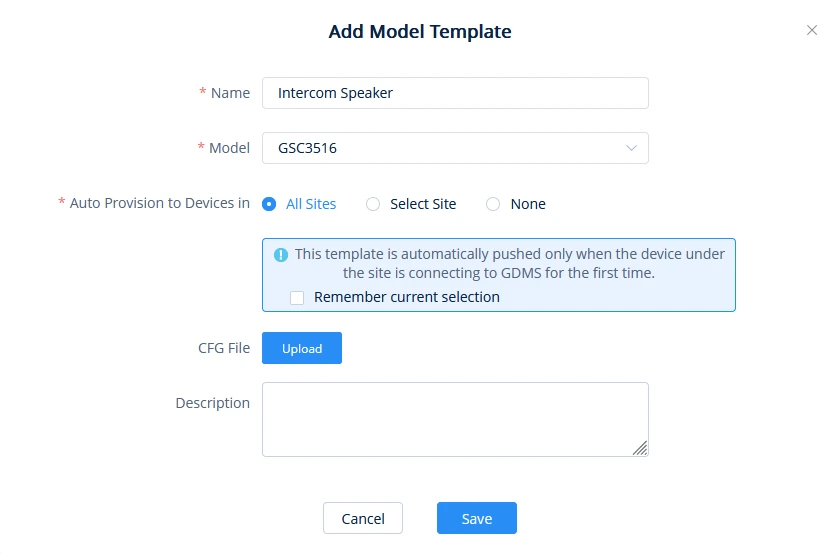
Add a model template on GDMS that corresponds to GSC3518HS by clicking on “Add Model Template” under Device Template→By Model
Add Model Template Window
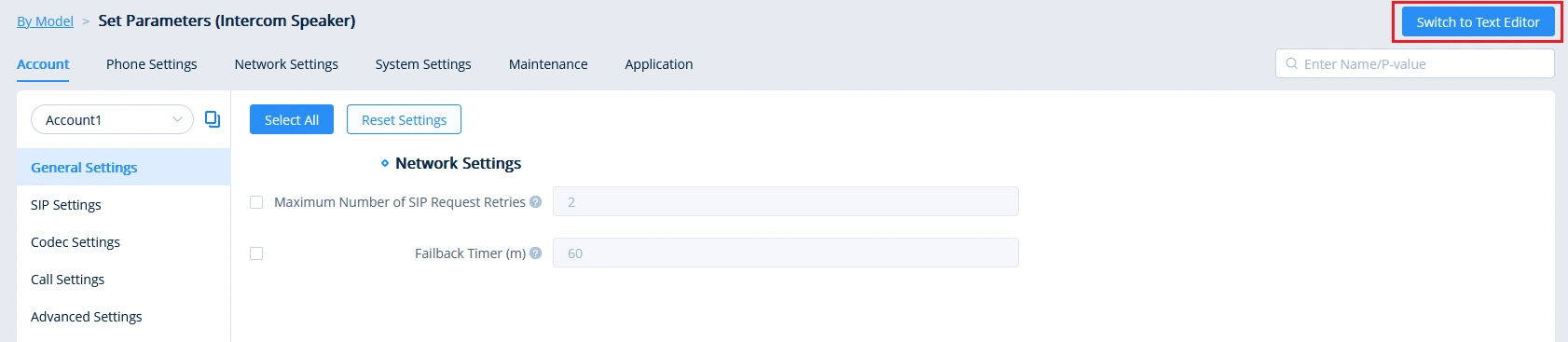
Once on the configuration page of the template, switch to the text editor.
Switch to Text Editor to Set Parameters
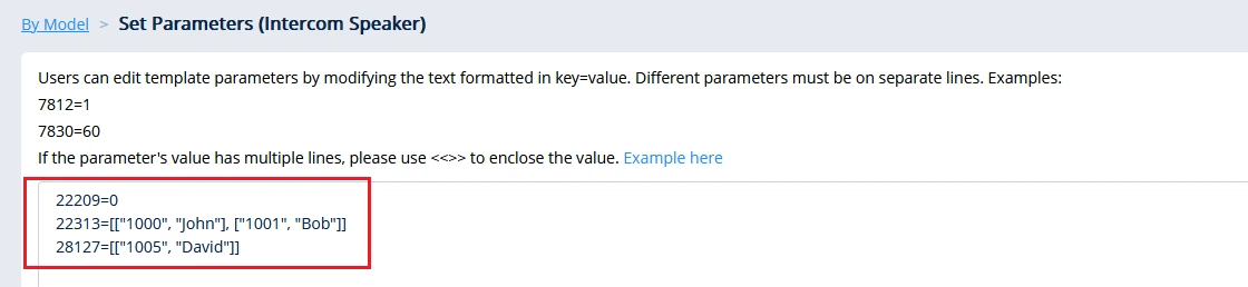
Enter the P-values according to your configuration requirements. In this example, we are blocking all calls on the Greylist, as well as calls from extension 1005 (David). Additionally, calls from extensions 1000 (John) and 1001 (Bob) will be allowed.
BlocklistAllowlistGreylist P values Configuration
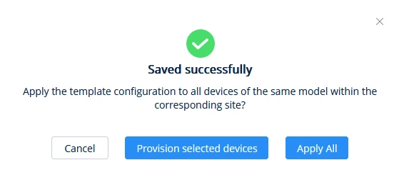
Click on Save and choose whether to apply the template to all models or select specific devices.
Saved Successfully Prompt
Under VoIP Device, the GSC3518HS will start provisioning.
GSC3518HS Provisioning
Once the configuration template has been successfully pushed to the device, the blocklist, allowlist, and greylist will appear as follows:
BlocklistAllowlistGreylist After Pushing the Configuration Template
Device Settings Page Definitions
Device Settings/General Settings
The RTP and NAT Settings section defines parameters for media transmission and network traversal. It allows configuration of RTP ports, NAT handling, and STUN server to ensure reliable audio delivery and SIP communication across firewalls and different network environments.
Local RTP Port
Defines the local RTP port pair used to listen and transmit.
The default value is 5004. The valid range is from 1024 to 65400.
Local RTP Port Range
Configures the range of local RTP port. Valid value is from 24 to 10000. Default is “200”
Use Random Port
Forces the device to use random ports for both SIP and RTP messages. This is usually necessary when multiple devices are behind the same full cone NAT. The default setting is “Yes”.
Note: This parameter must be set to “No” for Direct IP Calling to work.
Keep-alive Interval
Specifies how the device will send a Binding Request packet to the SIP server in order to keep the “ping hole” on the NAT router to open. The default setting is 20 seconds.The valid range is from 10 to 160.
STUN Server
Configures the URI of STUN (Simple Traversal of UDP for NAT) server. The device will send STUN Binding Request packet to the STUN server to learn the public IP address of its network. Only non-symmetric NAT routers work with STUN.
STUN Server Username
Fill in the username to validate STUN server.
STUN Server Password
Fill in the password to validate STUN server.
Use NAT IP
Configures the IP address for the Contact header and Connection Information in the SIP/SDP message. It should ONLY be used if it’s required by your ITSP. By default, the box is blank.
Device Settings – General Settings
Call Settings
The Call Settings section provides users with control over call behavior, audio notifications, and environmental sound settings. It includes options for managing call waiting, tones, ringing time, and noise cancellation. This ensures clear communication and flexible operation in various usage environments.
Enable Call Waiting
Enables call waiting feature. If it is disabled, it will reject the second incoming call during an active session without user’s knowledge. But this missed call record will be saved to remind users. The default setting is checked (enabled).
Enable Call Waiting Tone
Sets to play the call waiting tone along with LED indicator if there is another incoming call. If unchecked, only LED will indicate another incoming call. The default setting is checked (enabled).
Enable Busy Tone on Remote Disconnect
Configures wether to play busy tone when a call is disconnected remotely. Disabled by default
Multicast Tone
If enabled, there will be a prompt tone at the beginning and end of the multicast. Disabled by Default
Automatic Answer Ringing Time (s)
Configures the ring time for the unanswered call. The call will be automatically answered after timeout. Default is 0. The configuration range is 0–10 (s)
Busy Tone Ring Timeout (s)
Configures the timeout for Busy Tone during the call. Default is 30. The configuration range is 0–60 (s)
Auto Mute Mode
Configures whether to mute the call on entry automatically.
If set to “Disable“, then do not use auto mute function.
If set to “Auto Mute on Outgoing Call“, then mute automatically when the other party answers the outgoing call.
If set to “Auto Mute on Incoming Call“, then mute automatically when answers the incoming call
If set to “Mute on Incoming & Outgoing Call“, then mute automatically when the call gets through.
Note: This function only take effect when the device is from the idle status to call status. Users could click the Mute button on call interface to cancel the current mute status.
Filter Characters
Sets the characters for filter when dial out numbers. Users could set up multiple characters. For example, if set to “[()-]”, when dial (0571)-8800-8888, the character “()-“ will be automatically filtered and dial 057188008888 directly
Noise Suppression Mode
Noise Suppression Mode controls how background noise is reduced on the microphone audio.
AI Noise Suppression: Uses artificial intelligence to detect and remove background sounds (keyboard clicks, traffic, office noise, fans, etc.) while keeping voices clearer and more natural. It adapts better to changing or complex noise environments.
Classic Noise Suppression: Uses traditional DSP (audio filtering) to reduce constant background noise like steady hums or static. It’s simpler and uses fewer resources, but may affect voice quality more and is less effective with sudden or varied noises.
By default, it is set to “AI Noise suppression”
Device Settings – Call Settings
Ringtone
The Call Progress Tone (CPT) Configuration section allows users to customize regional tone settings for ringback, busy, reorder, and call-waiting signals. It ensures that the device matches local telephony standards or user preferences by adjusting tone frequencies, cadence, and volume for a consistent and familiar call experience.
Auto Config CPT by Region
Configures whether to choose Call Progress Tone automatically by region. If set to “Yes”, the device will configure CPT (Call Progress Tone) according to different regions automatically. If set to “No”, you can manual configure CPT parameters. The default setting is “No”.
Ring Back Tone
Busy Tone
Reorder Tone
Call-Waiting Tone
Configures tone frequencies according to user preference. By default, the tones are set to North American frequencies. Frequencies should be configured with known values to avoid uncomfortable high pitch sounds.
(Frequencies are in Hz and cadence on and off are in 10ms)
ON is the period of ringing (“On time” in “ms”) while OFF is the period of silence. In order to set a continuous ring, OFF should be zero. Otherwise it will ring ON ms and a pause of OFF ms and then repeats the pattern.
Please refer to the document below to determine your local call progress tones: http://www.itu.int/ITU-T/inr/forms/files/tones-0203.pdf
Call-Waiting Tone Gain
Adjusts the call waiting tone volume. Users can select “Low”, “Medium” or “High”. The default setting is “Low”.
Default Ring Cadence
Defines the ring cadence for the device. The default setting is: c=2000/4000.
Device Settings – Ringtone
Multicast/Group Paging
The Multicast Paging section enables real-time one-way audio announcements across multiple GSC devices within the same network. It provides options for paging priority, multicast listening, Push-to-Talk communication, and group paging management. This ensures efficient broadcast, emergency alerts, and prioritized voice transmission in multi-device environments.
Multicast Paging
Paging Barge
When this is enabled, an incoming multicast paging with a higher priority (Priority 1 = highest) can interrupt and end an active phone call. The call will be disconnected, and the paging announcement will play immediately.
Paging Priority Active
When this is enabled, if a paging announcement is already playing and another paging stream with a higher priority starts (Priority 1 = highest), the current page will stop, and the higher-priority page will play instead.
This option is disabled by default.
Multicast Listening
Priority
This defines which multicast stream is more important if multiple pages are received at the same time. Priority 1 is the highest. If two multicast announcements overlap, the one with the higher priority number (closer to 1) will be played first or will interrupt the lower-priority one (depending on your paging settings).
Use this to make emergency or critical paging the highest priority.
Listening Address
This is the multicast IP address and port the device will subscribe to and listen on.
The multicast range for your reference is: 224.0.1.0 → 239.255.255.255
Example format: 224.0.1.75:5000
Only pages sent to this exact multicast group and port will be heard on the device.
Each row allows the device to listen to a different multicast paging group.
Label
This is a friendly name you assign to the multicast group, for example, “Emergency Alerts” or “Warehouse Paging”.
It helps users/admins identify the purpose of that paging channel when it plays or when reviewing configuration; it does not affect the audio stream itself.
Application
This tells the device how to treat the incoming multicast stream:
VoIP: The multicast page is treated like a paging call. This is used for paging announcements to phones (typical office paging).
Audio: The device treats the stream as an audio broadcast rather than a paging call. This is normally used for background music or continuous audio streams.
If you’re setting up standard paging, choose VoIP.
Push-to-Talk/Group Paging
General Settings
Group Paging Address
This is the multicast IP address and port used for Push-to-Talk or group paging.
Example: 224.0.1.116:5001
When someone starts a PTT/group page, the device sends the audio to this multicast address. Any devices that are configured to listen to the same IP and port will receive and play the paging audio.
Note: Must be a multicast IP in the range 224.0.1.0–239.255.255.255, and the sender and receivers must match exactly.
IGMP Keep-alive Interval (s)
This controls how often the device sends IGMP membership reports (in seconds) to confirm it still wants to receive multicast traffic.
Example: 20 seconds
If the keep-alive isn’t sent, the network switch may assume the device left the multicast group and stop forwarding paging audio to it. So this value helps keep multicast delivery active and stable.
The range is 20 -120 (s), and the default value is set to 20 seconds
Emergency Group Paging Volume
Configures the default volume for group paging when the emergency channel/group is used.
The default value is set to 8 volume level, and the valid range is 1-8.
Push-to-Talk Config
PTT
Configures to enable or disable Push-to-Talk. Default is “Disabled”
Priority Channel
Set priority channel for Push-to-Talk. Push-to-Talk received on the priority channel will take precedence over active Push-to-Talk on the normal channel. Priorities go from 1 to 25.
Emergency Channel
Set the emergency channel for Push-to-Talk. The emergency channel has the highest priority. Push-to-Talk using the emergency channel will take precedence over Push-to-Talk on the priority or normal channel. Please note that Push-to-Talk to the emergency channel will not be rejected even when DND is enabled on the device.
Accept While Busy
Configures whether to accept Push-to-Talk while the device is in an active call. If set to “No”, the device will ignore Push-to-Talk while in an active call. If set to “Yes”, while in active Push-to-Talk talk, the device will accept Push-to-Talk if it has the same priority; if the device is in an active SIP call, the device will accept Push-to-Talk and put the SIP call on hold. Default is “Disabled”
Channel
Configures a Push-to-Talk (PTT) receive channel. This defines the channel settings, such as transport type, whether the device is allowed to receive PTT on this channel, and the channel label. Only enabling “Available” is required.
Paging Config
Group Paging
Allows to enable or disable group paging.
Priority Group
Configures priority paging group. Paging received on the priority group will take precedence overactive paging on the normal group.
Emergency Group
Set the emergency group for paging. The emergency group has the highest priority. Paging using the emergency group will take precedence over paging on priority or normal group.
Accept While Busy
Configures whether to accept paging while the device is in an active call. If set to “No”, the device will ignore paging while in an active call. If set to “Yes”, while in an active paging call, the device will accept other paging calls if it has the same priority. If the device is on an active SIP call, it will accept paging and hang up the call.
Group
Configures the paging group. Users can configure whether to use the group to accept and join a group, and its label. Only enabling “Available” is required.
Multicast/Group Paging
Network Settings Page Definitions
Ethernet Settings
The Ethernet settings section allows users to configure network connectivity parameters for both data and VoIP communication. It supports IPv4 and IPv6 configurations, VLAN tagging, QoS prioritization, and 802.1x authentication to ensure secure and optimized network performance across different deployment environments.
Internet Protocol
If IPv4 is selected, the device will be using IPv4 addressing, otherwise, it will be using IPv6 addressing. The default is IPv4 only.
Different Networks for Data and VoIP Calls
Configures whether to set up different networks for the phone data and the call. If set to “Yes”, you need to configure the data network and VoIP network respectively.
IPv4
IPv4 Address Type
Allows users to configure the appropriate network settings on the device. Users could select “DHCP”, “Static IP” or “PPPoE”. DHCP: Obtain the IP address via one DHCP server in the LAN. All domain values about static IP/PPPoE are unavailable (although some domain values have been saved in the flash.) PPPoE: Configures PPPoE account/password. Obtain the IP address from the PPPoE server via dialing. (When “Different Networks for Data and VoIP Calls” is set to Yes; it will be available for “Network Configuration of Data” only). Static IP: Manually configures IP Address, Subnet Mask, Default Router’s IP Address, DNS Server 1, and DNS Server 2. By default, it is set to “DHCP”.
DHCP VLAN Override
Controls whether the device receives its VLAN ID and VLAN Priority (802.1p) from the DHCP server instead of a manually-configured VLAN. VLAN information is delivered using DHCP Option 132 (VLAN ID) and 133 (VLAN Priority).
Disable (Default): Ignore DHCP VLAN information. The device will not change VLAN based on DHCP.
DHCP Option 132 and DHCP Option 133: The device reads VLAN ID (132) and VLAN Priority (133) directly from DHCP and applies them.
Encapsulated in DHCP Option 43 – The device extracts VLAN ID and Priority from Option 43 vendor data that contains Options 132 and 133. ➜ Requires enabling Allow DHCP Option 43 and Option 66 to Override Server under: Maintenance → Upgrade and Provisioning → Provision
Host name (Option 12)
Sets the name of the client in the DHCP request. It is optional but may be required by some Internet Service Providers.
Vendor Class ID (Option 60)
Configures the vendor class ID header in the DHCP request. Default setting is “Grandstream GSC3518HS”
DNS Server 1
Configures the primary DNS IP address.
DNS Server 2
Configures the secondary DNS IP address.
Preferred DNS Server
Configures the Preferred DNS Server.
Layer 2 QoS 802.1Q/VLAN Tag
Assigns the VLAN Tag of the Layer 2 QoS packets. Range is 0-4094
Layer 2 QoS 802.1p Priority Value
For Data
For VoIP Calls
Assigns the priority value of the Layer 2 QoS packets for Ethernet.
The Default value is 0.
Note: When “Different Networks for Data and VoIP Calls” is set to Yes, the user needs to set “Layer 2 QoS 802.1p Priority Value (Ethernet) for Data” and “Layer 2 QoS 802.1p Priority Value (Ethernet) for VoIP Calls”.
IPv6
IPv6 Address
Configures the appropriate network settings on the device. Users could select “Auto-configured” or “Statically configured”.
Static IPv6 Address
Enter the static IPv6 address in the “Statically configured” IPv6 address type.
IPv6 Prefix (64 bits)
Enter the IPv6 Prefix (64 bits) when Prefix Static is used in “Statically configured” IPv6 address type.
IPv6 Prefix Length
Enter the IPv6 prefix length in the “Statically configured” IPv6 address type.
IPv6 Gateway
The gateway when static IPv6 is used.
DNS Server 1
Configures the primary DNS IP address.
DNS Server 2
Configures the secondary DNS IP address.
Preferred DNS Server
Configures the Preferred DNS Server.
802.1x Mode
802.1x mode
Enables and selects the 802.1x mode for the device. The supported 802.1x modes are EAP-MD5, EAP-TLS, and EAP-PEAP. The default setting is “Disable”.
802.1x Identity
Enters the identity information for the selected 802.1x mode. (This setting will be displayed only if when mode = EAP-TLS or EAP-PEAP is enabled).
MD5 Password
Enter the MD5 Password for 802.1X EAP-MD5 mode.
CA Certificate
Uploads the CA Certificate file to the device. (This setting will be displayed only if the 802.1 X mode is enabled)
Client Certificate
Loads the Client Certificate file to the device. (This setting will be displayed only if the 802.1 X TLS mode is enabled)
Airplay
Users can transmit sound to GSC3518HS from devices by using AirPlay (macOS, iOS).
Below is an example of casting audio from an Apple device to GSC3518HS:
Access the GSC3518HS’s Web UI and go to Network Settings → Airplay.
Enable AirPlay and enter a projection name as well as a Pin Code for pairing.
Airplay Settings page
Swipe down from the top-right corner of the screen to open the Control Center, tap the AirPlay / Screen Mirroring icon, then select the GSC3518HS (Projection Name) from the list of available devices and enter the PIN Code when prompted.
OpenVPN® Settings
The OpenVPN® Settings section allows secure remote connections between the device and a private network through encrypted VPN tunnels. It provides options to import configuration files, specify server details, upload authentication certificates, and define encryption parameters for protected communication.
OpenVPN® Enable
Enable/Disable the OpenVPN® feature. Defaut setting is “Disabled”
Manual Import
Import OpenVPN® Configuration
Import the configuration file from the current computer. After importing, the local configuration will be overwritten and OpenVPN® function is automatically enabled. Note: Please import *.ovpn file
Local Configuration
OpenVPN® Server Address
The URL/IP address for the OpenVPN® server.
OpenVPN® Port
The network port for the OpenVPN® server. By default, it is set to 1194.
OpenVPN® Transport
Determines network protocol used for OpenVPN®: UDP or TCP.
OpenVPN® CA
OpenVPN® CA file (ca.crt) required by the OpenVPN® server for authentication purposes. Press “Upload” to upload the corresponding file to the device.
OpenVPN® Certificate
OpenVPN® Client certificate file (*.crt) required by the OpenVPN® server for authentication purposes. Press “Upload” to upload the corresponding file to the device.
OpenVPN® Client Key
The OpenVPN® Client key (*.key) required by the OpenVPN® server for authentication purposes. Press “Upload” to upload the corresponding file to the device.
OpenVPN® TLS Key
Click the button “Upload” to upload TLS key: Note: .key file
OpenVPN® TLS Key Type
Select the encryption type of the OpenVPN® TLS key. The available options are: TLS-Auth, TLS-Crypt, TLS-Crypt V2
OpenVPN® Cipher Method
Same cipher method must be used by the OpenVPN® server: Blowfish, AES-128, AES-256, Triple-DES
OpenVPN® Username
OpenVPN® authentication username (optional).
OpenVPN® Password
OpenVPN® authentication password (optional).
OpenVPN® Comp-lzo
Configures enable/disable the LZO compression. When the LZO Compression is enabled on the OpenVPN server, you must turn on it at the same time. Otherwise, the network will be abnormal. Default value is YES.
Additional Options
Additional options to be appended to the OpenVPN® config file. Note: Additional options are seperated by semicolon.
For example: comp-lzo no;auth SHA256
Please use with caution. Make sure that the options are supported by OpenVPN® and do not unnecessarily override other configurations above.
OpenVPN® Settings
Advanced Settings
The Advanced Settings section provides configuration options for optimizing network communication and device interoperability. It includes controls for DNS refresh and caching, LLDP/CDP discovery protocols, and QoS prioritization to enhance connectivity, call quality, and network efficiency.
Advanced Network Settings
DNS Refresh Timer (m)
Configures the refresh time (in minutes) for DNS query. If set to “0”, the phone will use the DNS query TTL from the DNS server response.
DNS Failure Cache Duration (m)
Configures the duration (in minutes) of the previous DNS cache when the DNS query fails. If set to “0”, the feature will be disabled. Note: Only valid for SIP registration.
Enable LLDP
Enables the LLDP (Link Layer Discovery Protocol) feature on the device. If it is set to “Yes”, the device will broadcast LLDP PDU to advertise its identity and capabilities and receive the same from physical adjacent layer 2 peers. The default setting is “Yes”.
LLDP TX Interval (s)
Configures the interval the device sends LLDP-MED packet. The default setting is 60s.
Enable CDP
Configures whether to enable CDP to receive and/or transmit information from/to CDP-enabled devices. The default setting is “Yes”.
Layer 3 QoS for SIP
Defines the Layer 3 packet’s QoS parameter for SIP messages in a decimal pattern. This value is used for IP Precedence, Diff-Serv, or MPLS. The default setting is 26 which is equivalent to the DSCP name constant CS6.
Layer 3 QoS for RTP
Defines the Layer 3 packet’s QoS parameter for RTP messages in a decimal pattern. This value is used for IP Precedence, Diff-Serv or MPLS. The default setting is 46 which is equivalent to the DSCP name constant CS6.
HTTP/HTTPS User-Agent
Configures the user-agent for HTTP/HTTPS request.
SIP User-Agent
Defines the SIP User-Agent header value sent by the device. If the string contains $version, it will automatically be replaced with the device’s actual firmware/system version at runtime.
Proxy
HTTP Proxy
Specifies the HTTP proxy URL for the phone to send packets to. The proxy server will act as an intermediary to route the packets to the destination
HTTPS Proxy
Specifies the HTTPS proxy URL for the phone to send packets to. The proxy server will act as an intermediary to route the packets to the destination.
Bypass Proxy For
Defines the destination IP address where no proxy server is needed. The device will not use a proxy server when sending packets to the specified destination IP address.
Remote Control
Action URI Support
Enables the device to receive HTTP/HTTPS Action URI commands from external systems (e.g., PBXs, provisioning tools, automation systems). When enabled, the device will execute supported actions when a valid Action URI request is received.
Action URI Allowed IP List
List of IP addresses allowed to send Action URI requests to this device. Supports single IPs, IP ranges, or subnets (comma-separated). If set to “any”, Action URI requests are accepted from all IP addresses.
For security, it is recommended to allow only trusted source IPs.
System Settings Page Definitions
Time Settings
The Time Settings section allows the device to synchronize its date and time automatically with a network time server. It provides options to configure NTP parameters, time zones, and display formats, ensuring accurate timekeeping for logs, schedules, and communication functions.
NTP Server
Configures the URL or IP address of the NTP server. The device may obtain the date and time from the server.
Enable Authenticated NTP
Configures whether to enable NTP authentication. If enabled, a cryptographic signature appended to each network packet. If the key is incorrectly configured, the device will refuse to use the time provided by the NTP server. Default is Disabled
Allow DHCP Option 42 to Override NTP Server
When enabled, DHCP Option 42 will override the NTP server if it is set up on the LAN. Default is Enableld
DHCP Option 2 to Override Time Zone Setting
Allows device to get provisioned for Time Zone from DHCP Option 2 in the local server automatically. Default is Enabled
Time Zone
Specifies the local time zone for the device. It covers the global time zones and user can selected the specific one from the drop-down list.
Self-Defined Time Zone
Allows the user to manually define a custom time-zone string (including offset and DST rules). Use standard TZ syntax.
Date Display Format
Determines which format will be used to display the date.
It can be selected from the drop-down list:
Normal (YYYY/MM/DD)
MM/DD/YYYY
DD/MM/YYYY
Mon, Dec 29
The default setting is YYYY-MM-DD
Time Display Format
Specifies which format will be used to display the time. It can be selected from 12-hour and 24-hour format.
Time Settings
Security Settings
The Security Settings section provides administrators with tools to control device access and data protection. It includes configuration options for SSH, web access, and certificate validation to ensure secure remote management and encrypted communication between the device and management interfaces.
Web/SSH Access
Enable SSH
Enables/disables SSH access to the device. The default setting is “Yes”.
SSH Port
Customizes the SSH port. By default, SSH uses port 22.
HTTP Web Port
Configures the HTTP port under the HTTP web access mode.
HTTPS Web Port
Configures the HTTPS port under the HTTPS web access mode.
Enable User Web Access
The administrator can disable or enable user web access. This option is set to “No” by default. Note: After first time log in attempt, the user will be forced to change his initial user level password defined by the administrator.
Web Access Mode
Sets the protocol for the web interface.
HTTPS
HTTP
Disabled
Both HTTP and HTTPS
Default is “HTTPS”
User Login Timeout
Configures login timeout (in minutes) for the user. If there is no activity within the specified time, the user will be logged out, and the Web UI will go to the login page automatically.
Validate Server Certificates
When enabled, the device verifies the server’s TLS certificate against its trusted CA list to confirm the server identity. Connections to servers with invalid, expired, or untrusted certificates will be rejected.
If disabled, certificate validation is bypassed and the device will trust any certificate, this is not recommended except for testing or known self-signed environments. Enabled by default
User Info Management
User Password
New Password
Set new password for web GUI access as User. This field is case sensitive.
Confirm Password
Enter the new User password again to confirm.
Admin Password
Current Password
The current admin password is required to set a new admin password.
New Password
Set new password for web GUI access as Admin. This field is case sensitive.
Confirm Password
Enter the new Admin password again to confirm.
Client Certificate
Minimum TLS Version
Specifies the minimum TLS version allowed for the connection.
Default is TLS 1.2
Maximum TLS Version
Specifies the maximum TLS version allowed for the connection.
Default is Unlimited
Enable Weak TLS Cipher Suites
Defines the function for weak TLS cipher suites:
Enable Weak TLS Cipher Suites: Allows the use of older, less secure cipher suites for compatibility with legacy devices.
Disable Symmetric Encryption RC4/DES/3DES: Blocks outdated symmetric encryption algorithms (RC4, DES, 3DES) known to be vulnerable.
Disable Symmetric Encryption SEED: Disables the SEED cipher, a legacy 128-bit block cipher with limited modern support.
Disable All Weak Symmetric Encryption: Disables all weak or deprecated symmetric encryption algorithms to enforce stronger security.
Disable Symmetric Authentication MD5: Disables MD5 as a message authentication algorithm due to collision vulnerabilities.
Disable All Weak TLS Ciphers Suites: Disables all known weak TLS cipher suites, this ensures only strong and secure ciphers are used.
Default is “Disable All Weak TLS Ciphers Suites“
SIP TLS Certificate
The Cert File for the device to connect to SIP Server via TLS.
SIP TLS Private Key
The Cert Key for the device to connect to SIP Server via TLS.
SIP TLS Private Key Password
SSL Private key password used for SIP Transport in TLS/TCP.
Custom Certificate
Click on “Upload” to upload a custom certificate. The uploaded custom certificate will be used for SSL/TLS communication instead of the device default certificate.
Trusted CA Certificates
Upload/Delete
Click on “Upload” to upload a certificate from our computer or click “Delete” to delete the selected certificate
Load CA Certificates
The device will verify the server certificate based on the built-in, custom or both trusted certificates list.
Security Settings
Preferences
The Preferences section allows users to personalize device behavior and audio settings. It provides options for LED indicators, sound notifications, and volume adjustments, ensuring optimal visibility and audio performance based on user preference.
LED Management
Enable Missed Call Indicator
If enabled, the LED indicator on the upper right corner of the device will light up when there is missed call on the device.
Call Light
Select the LED prompt light during the call. The default light is green.
Audio Control
Call Volume
Move the slider to configure call volume
Ringtone Volume
Move the slider to configure ringtone volume
Media Volume
Move the slider to configure media volume
MIC Gain (dB)
Adjusts the microphone transmission gain. Increasing this value raises the mic input level and makes your outgoing audio louder; decreasing it lowers the transmitted audio level.
Volume Compensation
If enabled, the volume will be automatically adjusted within an appropriate range according to the ambient noise. Disabled by Default
Bootup Tone
If enabled, the GSC3518HS will emit a sound effect on bootup. The default setting is “enabled”.
Audio Output Mode
The Audio Output Mode option defines how the device routes its audio signal between the built-in speaker and the Line-out port. This allows flexibility depending on whether you want to use only the internal horn speaker, connect to an external amplifier, or use both simultaneously.
Speaker Only: The audio output is directed exclusively to the built-in speaker of the device. Use this mode when the horn’s internal speaker alone is sufficient for broadcasting announcements or alarms.
Lineout Only: The audio output is sent only to the Line-out port. This mode is used when connecting the device to an external amplifier, PA system, or powered speaker, bypassing the internal horn.
The default value is Speaker Only.
PoE Setting
PoE IN
Specifies the type of Power over Ethernet the device can receive from the upstream PoE switch or injector.
PoE 802.3af – Up to 15.4W input power
PoE+ 802.3at – Up to 30W input power
PoE++ 802.3bt – Up to 60–90W input power (depending on class)
The device detects the available PoE class automatically, but this field may be shown to indicate the supported/negotiated power level.
PoE OUT
Defines the PoE standard used to supply power to a connected downstream device (such as an IP phone, camera, or sensor).
PoE 802.3af – Provides up to 15.4W
PoE+ 802.3at – Provides up to 30W
The maximum output power depends on the PoE power available on PoE IN. If insufficient input power is available, PoE OUT may be limited or disabled.
Note: Switching PoE OUT will cause the downstream device to reboot.
Preferences
TR-069
The TR-069 feature enables remote device management through the CPE WAN Management Protocol, allowing service providers to configure, monitor, and maintain devices automatically via an ACS (Auto Configuration Server). It ensures centralized provisioning, secure authentication, and scheduled status reporting.
Enable TR-069
Sets the device to enable the “CPE WAN Management Protocol” (TR-069). The default setting is “Yes”.
ACS URL
Specifies URL of TR-069 ACS (e.g, http://acs.test.com), or IP address.
ACS Username
Enters username to authenticate to ACS.
ACS Password
Enters password to authenticate to ACS.
Periodic Inform Enable
Sends periodic inform packets to ACS. The default is “Yes”.
Periodic Inform Interval (s)
Configures to send periodic “Inform” packets to ACS based on a specified intervals. The default setting is 86400.
Connection Request Username
Enters username for the ACS to connect to the device.
Connection Request Password
Enters the password for the ACS to connect to the device.
Connection Request Port
Enters the port for the ACS to connect to the device.
CPE SSL Certificate
Uploads the client-side SSL certificate used by the device (CPE) to authenticate itself to the TR-069 ACS server when HTTPS/TLS is enabled.
CPE SSL Private key
Uploads the private key associated with the CPE SSL certificate. This key must match the uploaded certificate and is used for mutual TLS authentication with the ACS server.
Start TR-069 at Random Time
If enabled, TR-069 will send out the first INFORM message to the server on randomized timing between 1 to 3600 seconds after the device boots up.
Disabled by default.
TR-069 Settings
ONVIF
The ONVIF (Open Network Video Interface Forum) feature allows the speaker to integrate seamlessly with third-party Video Management Systems (VMS), NVRs, or network surveillance platforms that support the ONVIF protocol.
ONVIF Function
Enables or disables the ONVIF service on the device. When checked, the horn speaker will advertise itself on the network and accept ONVIF-based connections from compatible VMS or NVR systems.
ONVIF Username
Defines the username used by external ONVIF clients (e.g., VMS software) to authenticate and access the device.
ONVIF Password
Defines the password associated with the ONVIF username. The same credentials must be configured in the third-party ONVIF client for successful connection and control.
Alarm Settings
The Alarm Settings feature allows users to configure automated alarm actions and notifications. It supports scheduled triggers, audio playback, and call alerts, enabling the device to perform specific actions such as playing a tone or making a call when an alarm condition is met.
Alarm in (1,2)
Sensor Type
Defines the default electrical state of the input port.
Always On: The input circuit is normally open (inactive by default). The alarm triggers when the circuit is closed.
Always Off: The input circuit is normally closed (active by default). The alarm triggers when the circuit is opened.
Alarm Scheme
ALARM_IN
Selects which Alarm input to set for the trigger time.
Cycle Time
Configures the cycle time. If set to “Daily”, it will trigger the function every day. If set to “Period of time”, it will trigger the function according to the set time period. The default value is “Daily”.
Time
Set the activation time, up to 3 times. When the activation time is not set, the default time is full day.
Frequency
Set the activation frequency from Monday to Sunday, which can be selected from the whole week. The default value is not selected.
Linkage Function
Play Audio
When enabled, plays a pre-recorded audio file automatically when the alarm input is triggered.
Prompt Tone
Selects the audio file that will be played through the device speaker when the alarm is triggered.
Play Rules
Defines how the audio prompt is played:
Maximum Duration – The audio will stop after the specified time (in seconds), even if the file is longer.
Number of Loops – The audio file will repeat the specified number of times.
Number of Loops
The prompt tone will loop for the set number of times and then stop. The valid range is 1-10, the default value is set to 1
Maximum Duration (s)
Specifies the maximum playback time in seconds when Maximum Duration is selected under Play Rules.
Make Call
Initiates a SIP call to a preconfigured number or extension when the alarm is activated, allowing real-time alerting.
Dialed Number
Specifies the SIP extension/number that will be called when the alarm event occurs.
Call RTSP Video Source
Configure whether to include RTSP video content when a call is triggered, when this is enabled, you can define the address of the third-party video stream.
Device Name
Friendly name or identifier for the RTSP device/source used for reference or display.
Connection Type
Specifies the RTSP transport protocol used for the stream (e.g., RTSP over UDP or TCP, or using Multicast).
RTSP Address
The full RTSP URL of the video source to be streamed during the alarm (for example: rtsp://[IP]:[port]/music.mp3).
RTSP Username
Username for authenticating to the RTSP stream, if authentication is required.
RTSP Password
Password for the RTSP user account.
Hang Up
Hanging up the current call when the switch is triggered, such as SIP calls, multicasts, etc. When the option is checked together with dialing: if there is a current call, the existing call will be hung up first, and dialing will be performed only when the switch is triggered for the second time; if there is no current call, dialing will be performed when the switch is triggered for the first time, and the call will be hung up when the switch is triggered for the second time.
Linked Alarm Ouput
Activates the device’s alarm output port to trigger an external device (such as a strobe light or siren) when the input alarm is detected.
Alarm Hold Time (seconds)
Defines how long the alarm state remains active (in seconds). This affects how long associated actions (audio, calls, relay output, etc.) stay active before automatically stopping. Default value is 5 (s), and the valid range is 0-1800 (s)
Alarm settings
Backup/Restore
The Backup/Restore page is used to back up data or import backup files to restore data. Users can start the Backup by clicking on “Backup”.
BackupRestore
Maintenance Page Definitions
Upgrade and Provisioning
Upgrade and Provisioning/Firmware
This section allows users to update the device firmware either by manually uploading a file or by configuring automatic upgrades through a network server. Firmware paths, credentials, and file matching options can be set, and users can trigger an upgrade check to detect and install newer versions.
Current Version
Displays the current firmware version
Upgrade via Manually Upload
Upload Firmware File to Update
Allows users to load the local firmware to the device to update the firmware.
Upgrade via Network
Firmware Upgrade via
Configures firmware upgrade method as TFTP, HTTP, HTTPS, FTP or FTPS. Default is HTTPS
Firmware Server Path
Sets IP address or domain name of firmware server. The URL of the server that hosts the firmware release.
Firmware Server Username
The username for the firmware server.
Firmware Server Password
The password for the firmware server.
Firmware File Prefix
Checks if firmware file is with matching prefix before downloading it. This field enables user to store different versions of firmware files in one directory on the firmware server.
Firmware File Postfix
Checks if firmware file is with matching postfix before downloading it. This field enables user to store different versions of firmware files in one directory on the firmware server.
Upgrade Detection
Upgrade
Click the “Start” button to check whether the firmware in the firmware server has an updated version, if so, update immediately.
Upgrade and Provisioning – Firmware page
Upgrade and Provisioning/Config File
This section allows users to manage device configuration either by manually downloading and uploading config files or by provisioning through a network server. Options are provided to select the transfer protocol, define server paths and credentials, apply prefix/postfix matching, and enable configuration file authentication or decryption.
Configure Manually
Download Device Configuration
Click to download the device configuration file in .txt format. Note: The p-values corresponding to the UCM Zero Config custom parameters are supported.
Upload Device Configuration
Upload config file to the device.
Configure via Network
Config Upgrade via
Configures the config upgrade method as TFTP, HTTP, HTTPS, FTP or FTPS. Default is HTTPS
Config Server Path
Sets IP address or domain name of configuration server. The server hosts a copy of the configuration file to be installed on the device.
Config Server Username
The username for the config server.
Config Server Password
The password for the config server.
Config File Prefix
Checks if configuration files are with matching prefix before downloading them. This field enables user to store different configuration files in one directory on the provisioning server.
Config File Postfix
Checks if configuration files are with matching postfix before downloading them. This field enables user to store different configuration files in one directory on the provisioning server.
Authenticate Conf File
Sets the device to authenticate configuration file before applying it. When set to “Yes”, the configuration file must include value P1 with phone system’s administration password. If it is missed or does not match the password, the device will not apply it. Default setting is “No”.
XML Config File Password
Decrypts XML configuration file when encrypted. The password used for encrypting the XML configuration file is using OpenSSL.
Upgrade and Provisioning – Config File page
Upgrade and Provisioning/Provision
This section defines how the device automatically checks for and applies firmware and configuration updates, including scheduling options, DHCP override rules, and provisioning priority. Users can control upgrade frequency, randomization, server discovery via DHCP options, and the order in which configuration files are downloaded and applied, including support for 3CX auto-provisioning.
Auto Upgrade
Automatic Upgrade
Specifies when the firmware upgrade process will be initiated; there are 4 options:
No: The device will only do upgrade once at boot up.
Yes, check for upgrade periodically: User needs to specify an Interval (m).
Check every day: User needs to specify “Hour of the day (0-23)”.
Check every week: User needs to specify “Hour of the day (0-23)” and “Day of the week (0-6)”.
Note: Day of week is starting from Sunday. The default setting is “No”.
Automatic Upgrade Check Interval (m)
This defines how often the device will contact the firmware server to check for a new firmware version. The value is in minutes, for example, 10080 minutes = 7 days, so the device will check once per week.
Hours of the Day (0-23)
Configures the hour of the day to check the firmware or config server for firmware upgrade or configuration file changes.
Day of the Week (0-6)
Configures the hour of the day to check the firmware or config server for firmware upgrade or configuration file changes.
Start Upgrade at Random Time
Configures whether the device will upgrade automatically at a random time within the configured time interval. Disabled by default.
Firmware Upgrade and Provisioning
Defines the device’s rules for automatic upgrade. It can be selected from:
Always Check for new firmware
Check new firmware only when F/W pre/suffix changes,
Always skip the Firmware Check.
The default setting is “Always Check for new firmware”.
DHCP Option
Allow DHCP Option 43 and Option 66 to Override Server
If set to “Yes” on the LAN side, the device will reset the CPE, upgrade, network VLAN tag and priority configuration according to option 43 sent by the server. At the same time, the upgrade mode and server path of the configuration upgrade mode will be reset according to option 66 sent by the server
If set to “Prefer, fallback when failed”, the device can fallback to use the configured provisioning server under its Firmware and Config server path in case the server from DHCP Option fails.
The default setting is “Yes”.
Allow DHCP Option 120 to Override SIP Server
When enabled, the device will use the SIP server address provided through DHCP Option 120 to override the configured SIP server.
The default setting is “Disabled”.
Additional Override DHCP Option
Configures additional DHCP Option to be used for firmware server instead of the configured firmware server or the server from DHCP Option 43 and 66. This option will be effective only when “Allow DHCP Option 43 and Option 66 to Override Server” is enabled. There are 3 options:
None
Option 150
Option 160
The default setting is “Option 150”
Allow DHCP Option 242 (Avaya IP Phones)
Enables DHCP Option 242. Once enabled, the device will use the configuration info issued by the local DHCP in Option 242 to configure proxy, transport protocol and server path. The default setting is “Disabled”.
Config Provision
Config Provision
Device will download the configuration files and provision by the configured order. Use arrow buttons to add and order configuration files.
Download and Process All Available Config Files
By default, the device will provision the first available config in the order of cfgMAC, cfgMAC.xml, cfgMODEL.xml, and cfg.xml (corresponding to device specific, model specific, and global configs). If set to “Yes”, the device will download and apply (override) all available configs in the order of cfgMAC, cfg.xml, cfgMODEL.xml, cfgMAC.xml.
3CX Auto Provision
If enabled, the device will send SUBSCRIBE requests to the multicast address in LAN during bootup for automatic provisioning. This feature requires 3CX server support. Default setting is “Enabled”.
Upgrade and Provisioning – Provision page
Upgrade and Provisioning/Advanced Settings
This section provides options to manage authentication behavior for firmware and configuration downloads, SIP NOTIFY security handling, SSL hostname validation, and access to AutoConfig services. It also includes the factory reset control to restore the device to default settings when needed.
Send HTTP Basic Authentication By Default
Determine whether to send basic HTTP authentication information to the server by default when using wget to download firmware or config file. If set to “Yes”, send HTTP/HTTPS user name and password no matter the server needs authentication or not. If set to “No”, only send HTTP/HTTPS user name and password when the server needs authentication. The default value is “Disabled”.
Enable SIP NOTIFY Authentication
Device will challenge NOTIFY with 401 when set to “Yes”. The default value is “Enabled”.
Validate Certificate Chain
Configures whether to validate the server certificate when downloading the firmware/config file. If set to “Yes”, the device will download the firmware/config file only from the legitimate server. Disabled by default.
Allow AutoConfig Service Access
Set to allow access to the AutoConfig service. If not checked, access to service.ipvideotalk.com will be disabled. The default value is “Enabled”.
Factory Reset
Resets the device to the default factory setting mode by clicking on “Start” button.
Upgrade and Provisioning – Advanced Settings page
System Diagnosis
The System Diagnostics section helps administrators monitor device activity, troubleshoot network issues, and collect detailed logs for debugging. It includes tools for syslog configuration, packet capture, and network testing functions like ping and traceroute.
Syslog
Syslog Protocol
Select the transport protocol over which log messages will be carried.
UDP: Syslog messages will be sent over UDP.
SSL/TLS: Syslog messages will be sent securely over TLS connection.
Syslog Server
The URL/IP address for the syslog server.
Syslog Level
Selects the level of logging for syslog. There are 4 levels from the dropdown list: DEBUG, INFO, WARNING and ERROR. The following information will be included in the syslog packet:
DEBUG: Sent or received SIP messages.
INFO: Product model/version on boot up, NAT related info, SIP message summary, Inbound and outbound calls, Registration status change, negotiated codec, Ethernet link up
WARNING: SLIC chip exception.
ERROR: SLIC chip exception, Memory exception.
Note: Changing syslog level does not require a reboot to take effect.
The default setting is “None”.
Syslog Header Format
Configures the preferred header format for Syslog. The options are:
Legacy (Default setting)
RFC3164 Compliant
The RFC3164 compliant header begins with “PRI” which represent both the Facility (0 – 23) and severity level (0 – 7) of the event. The message includes the timestamp, hostname, process id and the log message. For more information regarding the representation of the numerical values for the facility and severity, please refer to RFC3164.
Syslog Keyword Filter
Only send the syslog with keyword, multiple keywords are separated by comma. Example: set the filter keyword to “SIP” to filter SIP log.
Send SIP Log
Configures whether the SIP log will be included in the syslog messages. Default is “Disabled”
Packet Capture
With RTP Packets
Configures whether the packet capture file contains RTP or not. Then click “Start” to start Packet Capture or “Stop” to stop the Packet Capture.
With Secret Key Information
Configures whether the packet capture file contains secret key information or not. Then click “Start” to start Packet Capture or “Stop” to stop the Packet Capture.
Ping
Enter the URL into the textbox then click “Start” to begin the ping, Results will be shown below.
Traceroute
Enter the URL into the textbox then click “Start” to begin the Traceroute, Results will be shown below.
Remote Diagnostics
When enabled, this device will allow remote access and remote collection of logs. It will automatically end when it expires.
Note: Click on “Start”, then the Access Address and Expiration Time will be shown below.
Record
Record
Begins an audio recording session directly from the device’s microphone or input stream. This helps verify audio capture quality or troubleshoot voice transmission issues.
Recording List
Displays previously saved audio recordings stored on the device. Administrators can select a file from the list to manage it.
System Diagnostics page
Event Notification
Set the URL for events on the device web GUI, and when the corresponding event occurs on the device, the device will send the configured URL to the SIP server. The dynamic variables in the URL will be replaced by the actual values of the device before sending it to the SIP server, to achieve the purpose of event notification. Here are the standards:
The IP address of the SIP server needs to be added at the beginning, and the dynamic variables with a “/”.
The dynamic variables need to have a “$” at the beginning. For example: local=$local
If users need to add multiple dynamic variables in the same event, users could use “&” to connect with different dynamic variables. For example: 192.168.40.207/mac=$mac&local=$local
When the corresponding event occurs on the device, the device will send the MAC address and phone number to the server address 192.168.40.207.
Device Status
Bootup Completed
Configures the event URL when the device boots up.
Registered
Configures the event URL when an account in the device is registered successfully.
Unregistered
Configures the event URL when an account in the device is unregistered.
Log On
Configures the Action URL to send when log on is completed successfully.
Log Off
Configures the Action URL to send when log off is completed successfully.
Alarm Notification
Alarm Input Triggered
Defines the event URL when an alarm input (e.g., sensor or button) is activated.
Alarm Input Closed
Defines the event URL when the alarm input is deactivated (sensor returns to normal).
Alarm Output Triggered
Defines the notification or event when the alarm output (e.g., siren or relay) is activated.
Alarm Output Closed
Defines the notification or event when the alarm output is turned off.
Call Operation
Incoming Call
Configures the event URL when the device has an incoming call.
Outgoing Call
Configures the event URL when the device has an outgoing call.
Missed Call
Configures the event URL when the device has new a missed call.
Established Call
Configures the event URL when a call is established.
Terminated Call
Configures the Action URL to send when the device terminates a call.
Event Notification
Application Page Definitions
Broadcast
The Broadcast feature enables users to play, stream, or schedule background audio on GSC devices.
In Instant Playback, the Audio Source setting lets you choose what type of audio will be broadcast.
Speech Synthesis generates spoken announcements from predefined text using the device’s text-to-speech engine. This is ideal for alerts or informational messages that may change frequently.
Music, on the other hand, plays pre-uploaded audio files (such as .wav files) stored on the device, which is better suited for tones, prerecorded messages, or background audio.
Selecting the source determines whether the system outputs dynamically generated speech or fixed media files during playback.
Instant Playback
Audio Source
Selects the type of audio the device will broadcast. When set to Music, the system plays uploaded audio files stored on the device. When set to Speech Synthesis, the device generates audio dynamically from user-defined text using the built-in text-to-speech engine.
Synthesized Audio
Displays the list of available synthesized speech items created on the device. Each entry represents a text-to-speech message that can be selected and broadcast during Instant Playback. Multiple synthesized items can be created and managed from this list.
Add Synthesized Audio
Creates a new text-to-speech audio entry. Clicking Add opens the Speech Synthesis configuration window, where the message text, voice characteristics, and playback speed can be defined.
Name: Defines the label assigned to the synthesized speech entry. This name appears in the Synthesized Audio list and is used to identify the message during playback.
Voice Content: Specifies the text that will be converted into speech when the message is played. The device automatically processes this content through the text-to-speech engine.
Voice Type: Selects the voice gender used for text-to-speech output. Available options are Male Voice and Female Voice.
Speech Speed: Adjusts the playback speed of the synthesized voice. Moving the slider toward Slow decreases the speech rate, while moving it toward Fast increases the speech rate.
Music Mode
Please select the audio file type:
RTSP/HTTP stream: Set up the stream address to play online music. RTSP supports .ts and .mp3; HTTP supports .m3u, .m3u8, .pls. For example:
rtsp://[IP]:[port]/music.mp3
rtsp://[IP]:[port]/music.ts
http://[IP]:[port]/music.m3u
http://[IP]:[port]/music.m3u8
http://[IP]:[port]/music.pls
Local Music: choose locally from your computer the music to play.
Online Music: Stream online music from the web or from a 3rd party desktop music streaming software.
RTSP/HTTP stream address
This option allows the device to obtain audio from an RTSP or HTTP stream source.
Displays the audio tracks uploaded to the local storage or to an externally connected USB.
It supports .mp3 and .ogg audio formats only.
Share Music
Prompts a pop-up browser tab or window from which the music will be streamed, play music on PC first, and click to select the music window to be shared to the GSC. It is recommended to use the browser Chrome (72 and above), Edge (79 and above). Otherwise, it may be silent after sharing.
Timed playback
Click on “Add rule” to create Timed playback rule
Timed playback rule
Audio Source
Please select the audio file type from the list:
Music
Speech Synthesis
Synthesized Audio
Displays the list of available synthesized speech items created on the device. Each entry represents a text-to-speech message that can be selected and broadcast during timed Playback. Multiple synthesized items can be created and managed from this list.
Music Mode
If RTSP/HTTP stream is selected: Support RTSP or HTTP stream address to obtain audio. Supporting MP3, TS, M3U, and M3U8 formats.
If Local Music is selected: Please select local music, supporting MP3 and OGG formats.
Play Mode
Single play: play the music once at the set time.
Loop play: play music in a loop within the set time.
Play interval (s)
Configure the interval between the two playbacks. The valid range is 0-1800 seconds.
The Default value is 0 seconds.
Play Time
Set the trigger time, up to 3 items can be set. Click on “+” to add more
Frequency
Configures the activation frequency from Monday to Sunday. Up to 7 days can be selected. The default value is not selected.
Music
Playback Cascade
The Playback Cascade feature allows multiple GSC devices to synchronize audio playback across the same network segment, enabling one unit to act as a Master and others as Slaves for unified streaming or announcements.
Playback Cascade
Cascade role
Select the cascade role. Only cascading on the same network segment is supported and only one Master is allowed. You can set the cascade role to either “Transmitter”, “Reciever”, or “None”, By Default, it is set to “Reciever”.
Multicast Address
Defines the multicast address that will be used by the speakers to play audio.
Forwarding Category
This option selects the type of audio to forward. It can be Music Media, Call, or Alarm.
Current Transmitter Address
Displays the local IP address of the transmitter speaker.
Trigger Time
Gives the option to add a triggering time for the Playback
Playback time
Configures the activation time. Up to 3 entries can be configured. When the activation time is not set, the default time is a full day.
Frequency
Configures the activation frequency from Monday to Sunday. Up to 7 days can be selected. The default value is not selected.
Playback Cascade
GSC Assistant
The GSC Assistant section allows users to manage device visibility and identification within the GSC Assistant App, making it easier to detect and organize GSC devices during setup or maintenance.
GSC Assistant
Managed by GSC Assistant App
Configures the ability for the device to be detectable by the GSC Assistant App. Enabled by Default.
Device Label
Defines under what label the GSC shows up during the scan.
Zone Music
The Zone Music feature allows administrators to manage background music streaming and scheduling across multiple GSC speaker devices. It provides centralized control over playback sources, zones, and timing, enabling synchronized announcements or background music distribution over multicast or unicast streaming.
Zone Music / Zone Manager Settings
GSC Zone Manager
Enables or disables the Zone Manager functionality. When enabled, the device acts as a controller to manage and synchronize music playback to other connected GSC speakers.
Zone Music / Managed Devices
Device Model
Displays the model number of the connected GSC speaker (e.g., GSC3518HS).
MAC Address
Shows the unique hardware address of the device.
IP Address
Lists the device’s assigned IP address.
Software Version
Indicates the current firmware version installed on the device.
Hardware Version
Displays the device’s hardware revision.
Device Status
Shows whether the device is ready for playback (e.g., Playable).
Partition Status
Displays whether the device is assigned to a zone (e.g., Not Partitioned).
Label
The custom label name assigned to the device for easier identification.
Operation
Provides quick access to manage or monitor the device (e.g., locating the unit or changing the label of the device).
Import
Imports new speakers to the managed devices
Export
Exports the information of the added speakers
Add Device
Click the button add device to discover nearby GSC speakers and locate and add them as managed devices.
Add to Zone
When you select a device and click Add to Zone, you assign it to one (or more) logical broadcast zones. Then, when a page or instant playback is triggered to that specific zone, all devices in that zone will play the audio at the same time. This makes it easy to organize speakers by area (e.g., Reception, Warehouse, Office Floor 1, etc.) and control where announcements are heard without affecting other locations.
Refresh
When you click Refresh, fields like IP Address, Software Version, Device Status, Partition Status, and connectivity state are reloaded so you see the current condition of each device instead of cached data. It does not reboot the device or change any settings — it just updates what you’re seeing on the screen.
Zone Music / Zone Management
Add / Delete
Used to create or remove music zones. A zone can include one or multiple GSC speakers for synchronized playback.
Zone Name
Custom name for each playback zone (e.g., “Lobby,” “Office,” “Hall”).
Number of Playable GSCs / Number of Associated GSCs
Displays the number of active (playable) speakers and total speakers assigned to the zone.
Operation
Options to edit, delete, or view the details of the zone configuration.
Import
Imports informations about new zones.
Export
Exports the zones information.
Zone Music / Playback
Music Mode
Selects the playback source:
RTSP/HTTP Stream: Play music streamed from a network source.
Local Music: Play audio files stored locally on the device.
RTSP/HTTP Stream Address
Defines the streaming address (URL) from which audio will be received.
Transmission Mode
Determines the method of stream distribution:
Multicast: One-to-many streaming for multiple devices in the same network.
Unicast: One-to-one transmission.
IPv4 Listening Address
Multicast or unicast listening address for IPv4 streams.
IPv6 Listening Address
Listening address for IPv6-based streams.
Select Zones and Devices
Displays available zones or standalone devices to assign for playback.
Save
Saves playback configuration.
Save and Play
Immediately saves the settings and starts playback.
Reset
Clears all current playback configurations.
Zone Music / Timed Playback
Music Mode
Selects playback source: RTSP/HTTP Stream or Local Music.
RTSP/HTTP Stream Address
Specifies the network stream URL for scheduled playback.
Play Mode
Defines playback behavior:
Single Play: Plays the audio once at scheduled time.
Loop Play: Repeats playback continuously.
Play Time
Sets the exact time when playback should start. Multiple times can be added. Maximum 3 different timeslots.
Frequency
Specifies on which days of the week playback should occur (e.g., Monday–Friday).
Transmission Mode
Defines whether streaming uses Multicast or Unicast.
IPv4 Listening Address
Address and port for IPv4 streaming.
IPv6 Listening Address
Address and port for IPv6 streaming.
Select Zones
Allows selecting one or multiple zones for the scheduled playback.
OK / Cancel
Confirms or cancels the timed playback configuration.
Diagnostic Page Definitions
Microphone Test
An audio loop test is used to test the MICs. Each one of the MICs is tested separately.
Microphone Test
Speaker Test
Built-in Speaker Test is used to test the devices by playing a piece of music in order to verify the sound quality.
Speaker Test
LED Test
The LED Test is used to test the availability of the four colored LEDs and their intensity. The colors of LEDs available are Green, Red, and Blue.
LED Test
Certificate Verify
Certificate Verify is used to test the validity of the existing certificate.
Certificate Verify
Reset Button Test
The Reset Button Test is used to test the Reset button. During the test, the reset button doesn’t trigger a factory reset; this feature allows the user to check if the button is responding.
Alarm Input Test
Click on “Start Testing” to start the testing for the Alarm in the test.
Alarm Input Test
Alarm Output Test
Click on “Start Testing” to start the testing for the Alarm output test.
Alarm Output Test
Line IN Test
This option is used to verify that external audio sources (like a microphone or music player) connected to the Line In port are being properly received by the device.
Line IN Test
Line Out Test
This option is used to confirm that audio output from the device is correctly transmitted through the Line Out port to external speakers or amplifiers.
Line Out Test
Upgrading the Device
The GSC3518HS offers multiple methods for upgrading the device’s firmware. Users can either upload the firmware file directly, downloaded from the official Grandstream firmware website, or configure an HTTP/HTTPS/FTP/TFTP server to automatically retrieve the firmware.
For more information on firmware upgrades for Grandstream devices, please refer to the Firmware Upgrade Guide available on the official Grandstream documentation.
To upgrade the GSC3518HS locally, follow the steps below:
Download the official (or beta) firmware for the relevant device (GSC3518HS in this case).
On the GSC3518HS Web UI, navigate to Maintenance → Upgrade and Provisioning → Upgrade.
Select the option to Upload Firmware.
Upload the firmware file to the device and wait for the upgrade process to complete.
The GSC3518HS can be upgraded directly from the Web UI using the above procedure. For more details on the configuration options, please refer to the Upgrade and Provisioning section of the Web UI.
Factory Reset
To perform a factory reset via the Web GUI, navigate to Maintenance → Upgrade and Provisioning → Advanced Settings, click on the “Factory Reset” button, then click on “OK” to confirm the factory reset.
Factory reset via web GUI for GSC3518HS
Power Dissipation and Advertisement
This table summarizes the available power input options for the GSC3518HS, including DC and PoE (802.3af/at/bt) power classes. It also lists the corresponding maximum speaker power consumption for each power mode, helping you match deployment requirements with the appropriate power source.
Product
POWER CLASS
MAX SPEAKER POWER CONSUMPTION
GSC3518HS
DC Input
DC24V/4A~48V/2A
48W
802.3af
CLASS 0/3
7.7W
802.3at
CLASS 4
15W
802.3bt
CLASS 5
33W
CLASS 6
33W
CLASS 7
40W
CLASS 8
40W
For more information on the GSC35xx power consumption, please check the following guide: GSC35XX Power Consumption.
CHANGE LOG
This section documents significant changes from previous versions of the user manual for the GSC3518HS device. Only major new features or major document updates are listed here. Minor updates for corrections or editing are not documented here.



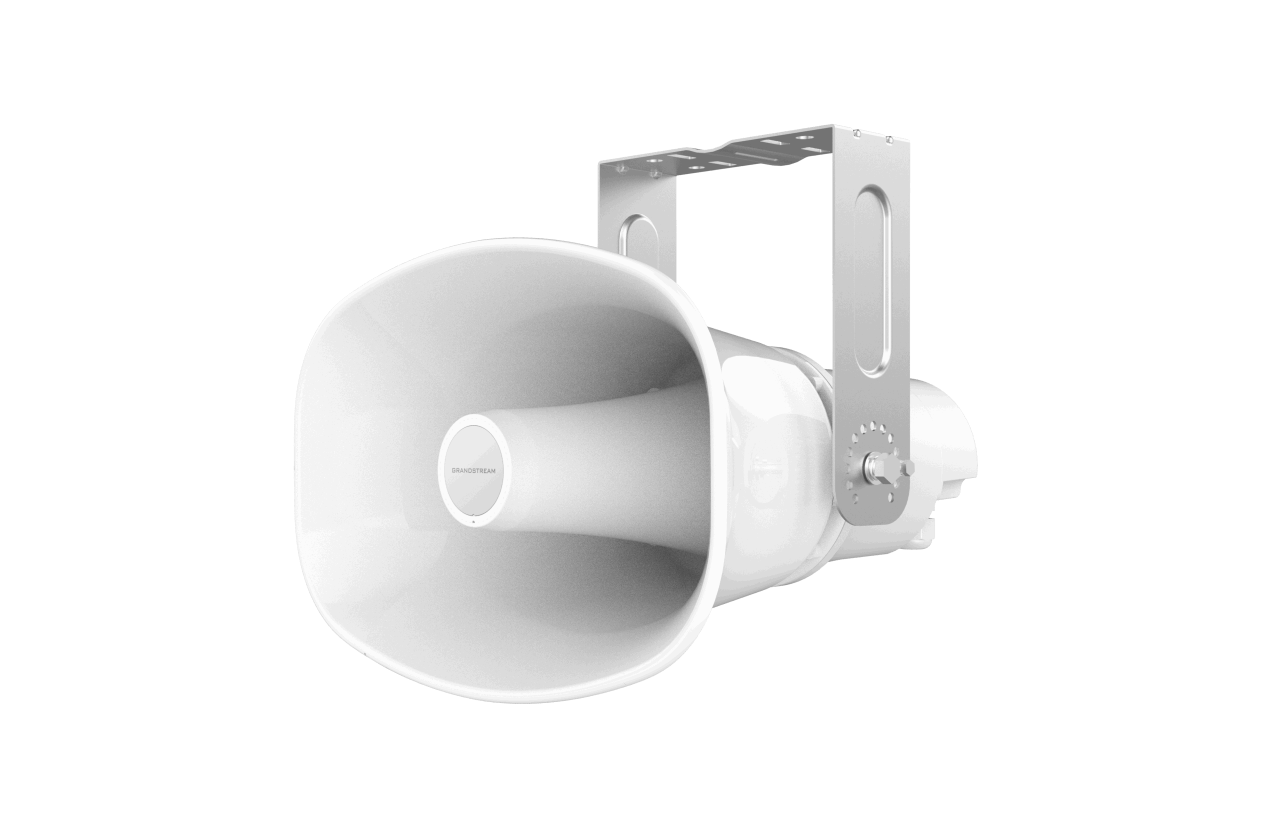

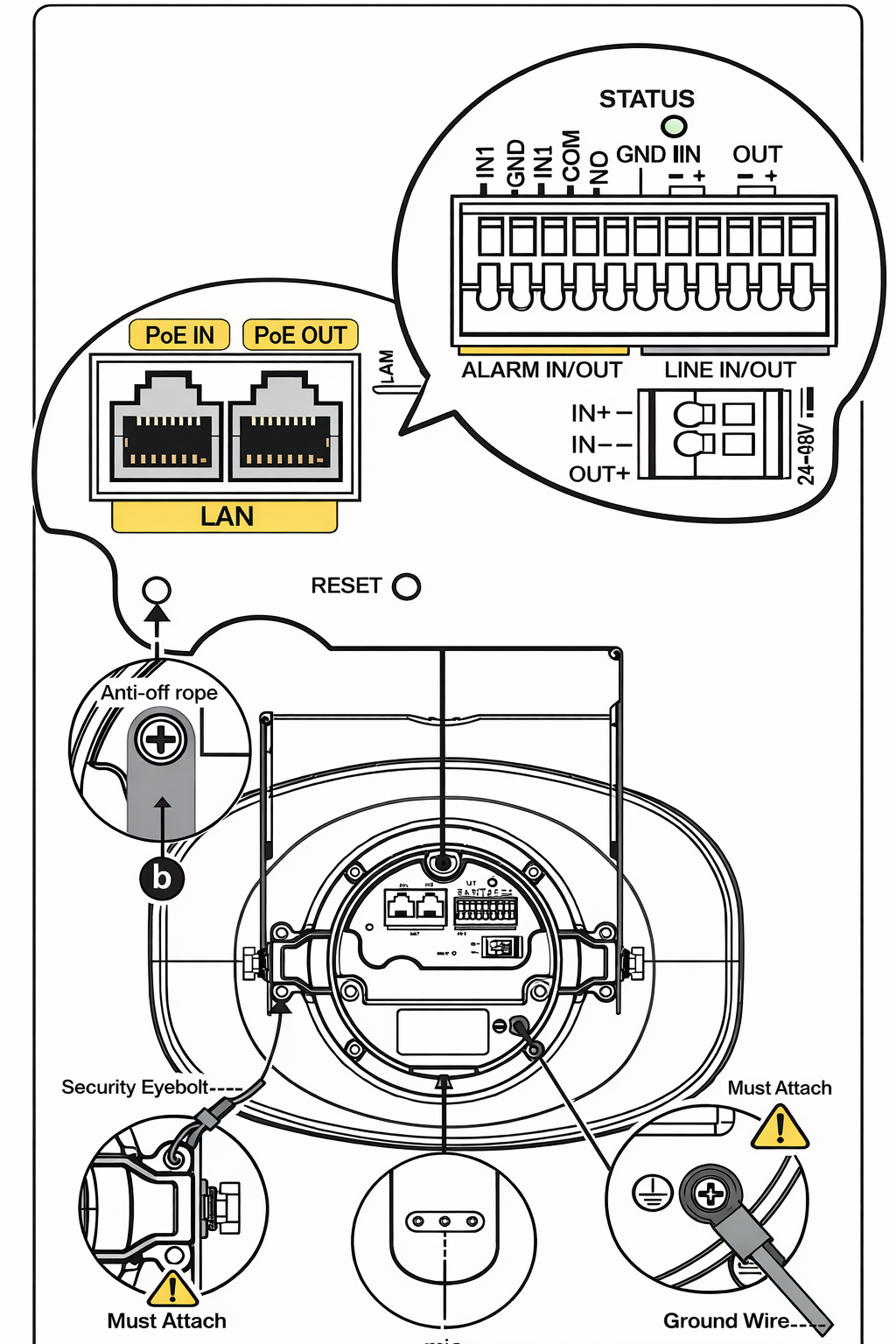
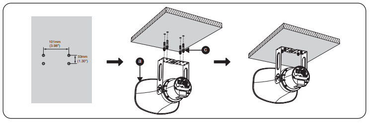
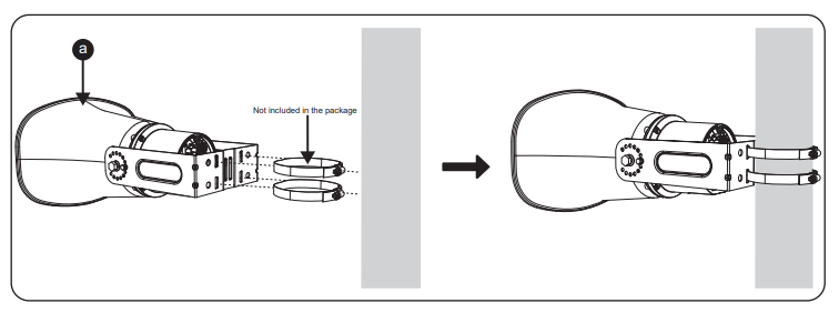
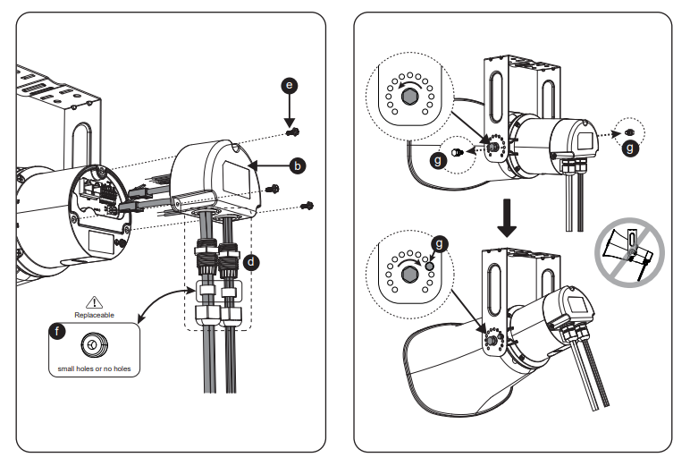
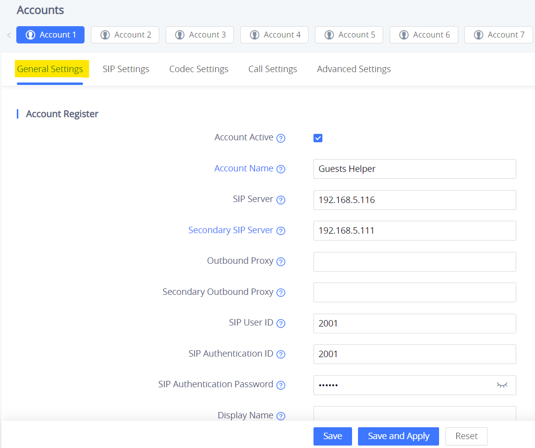

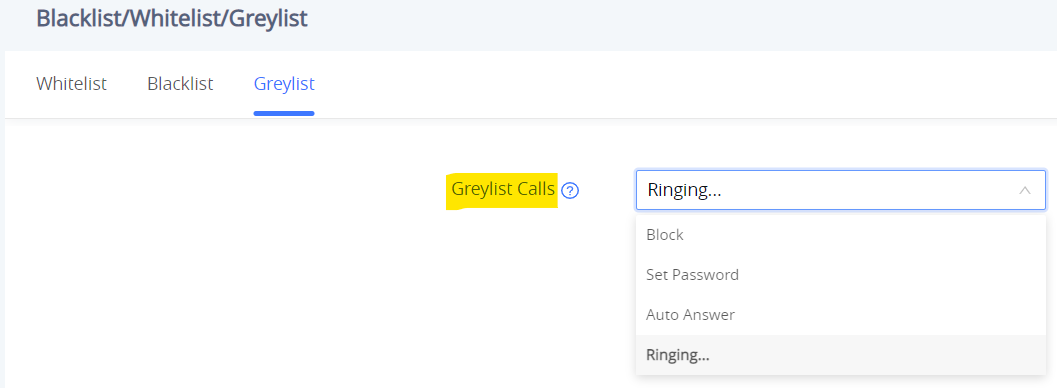
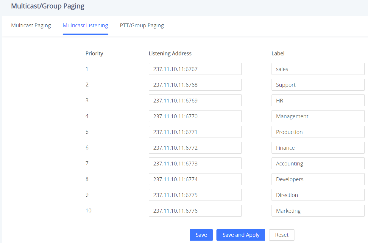
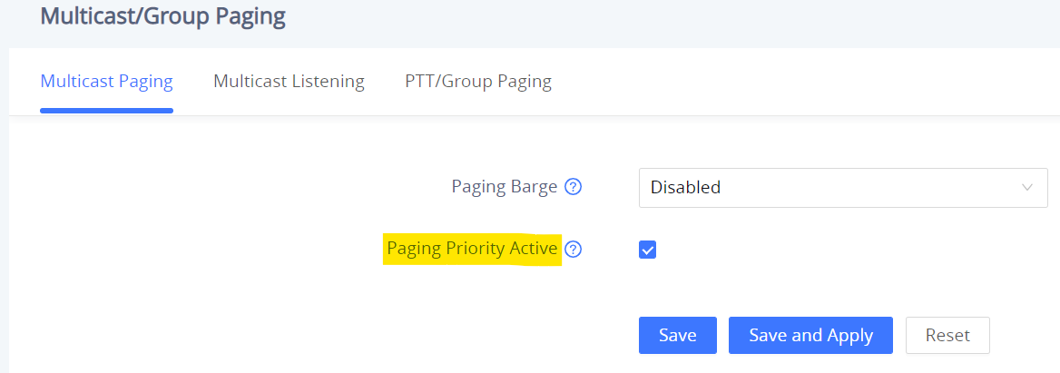
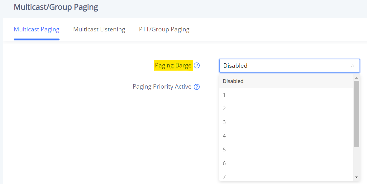
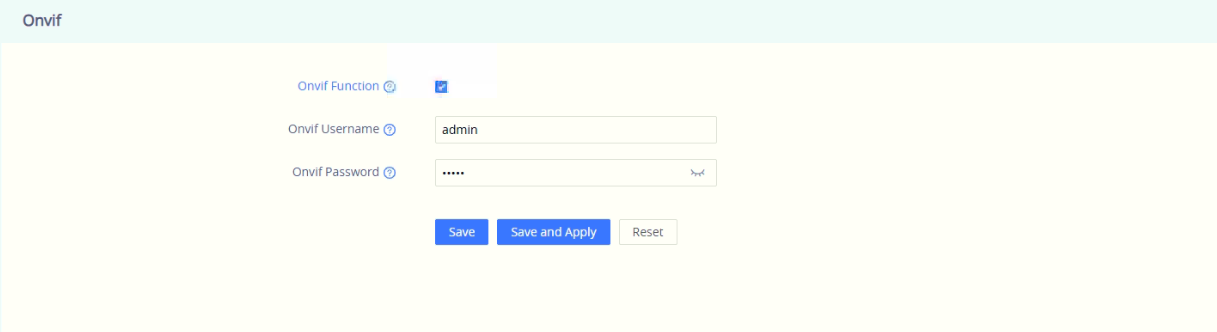
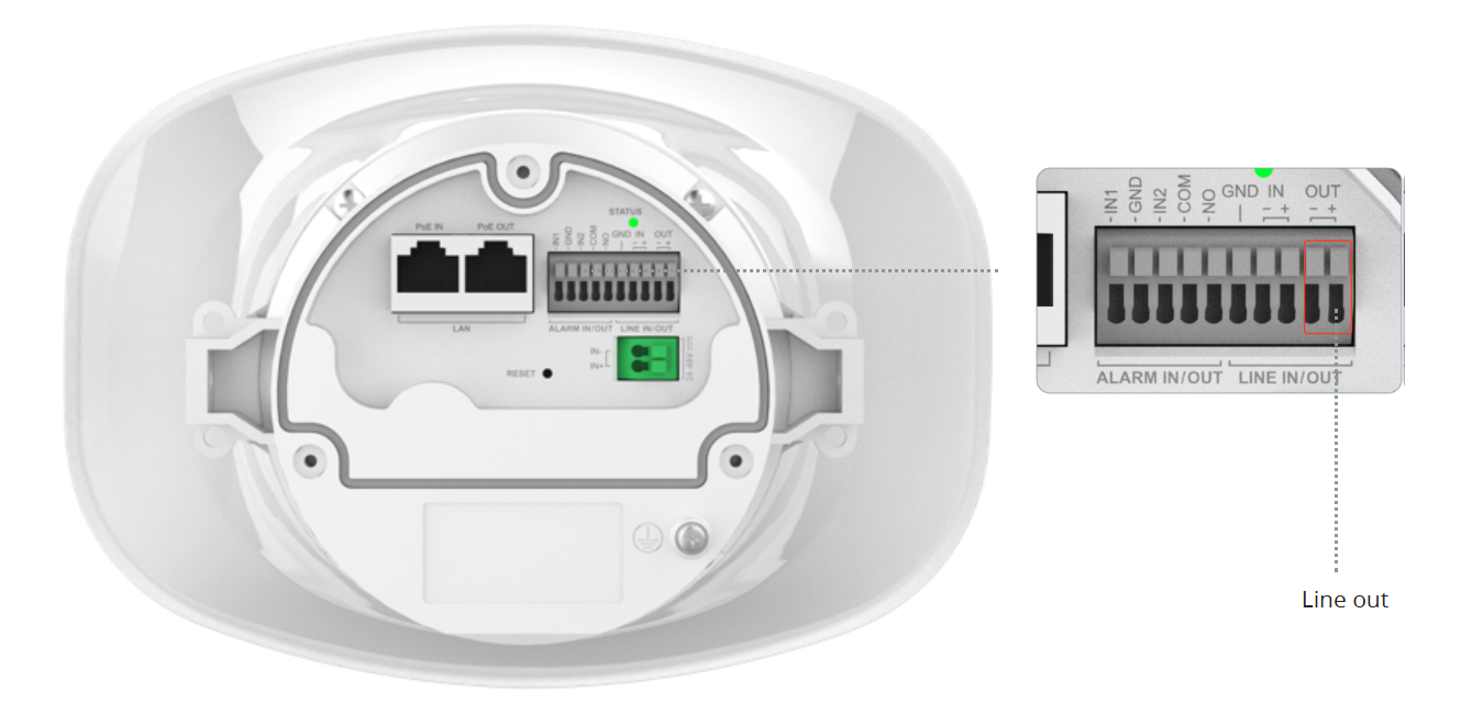
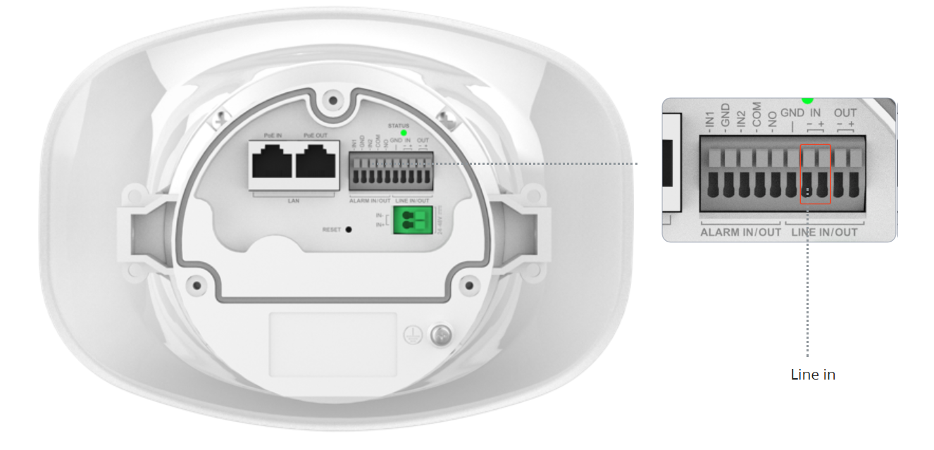
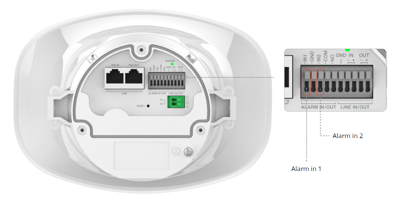
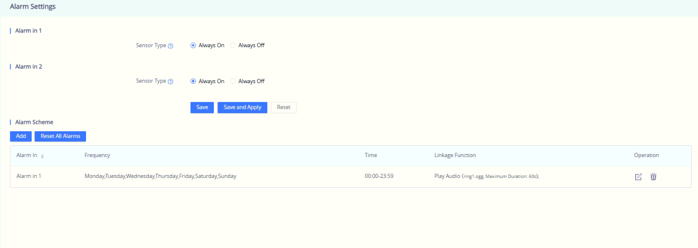
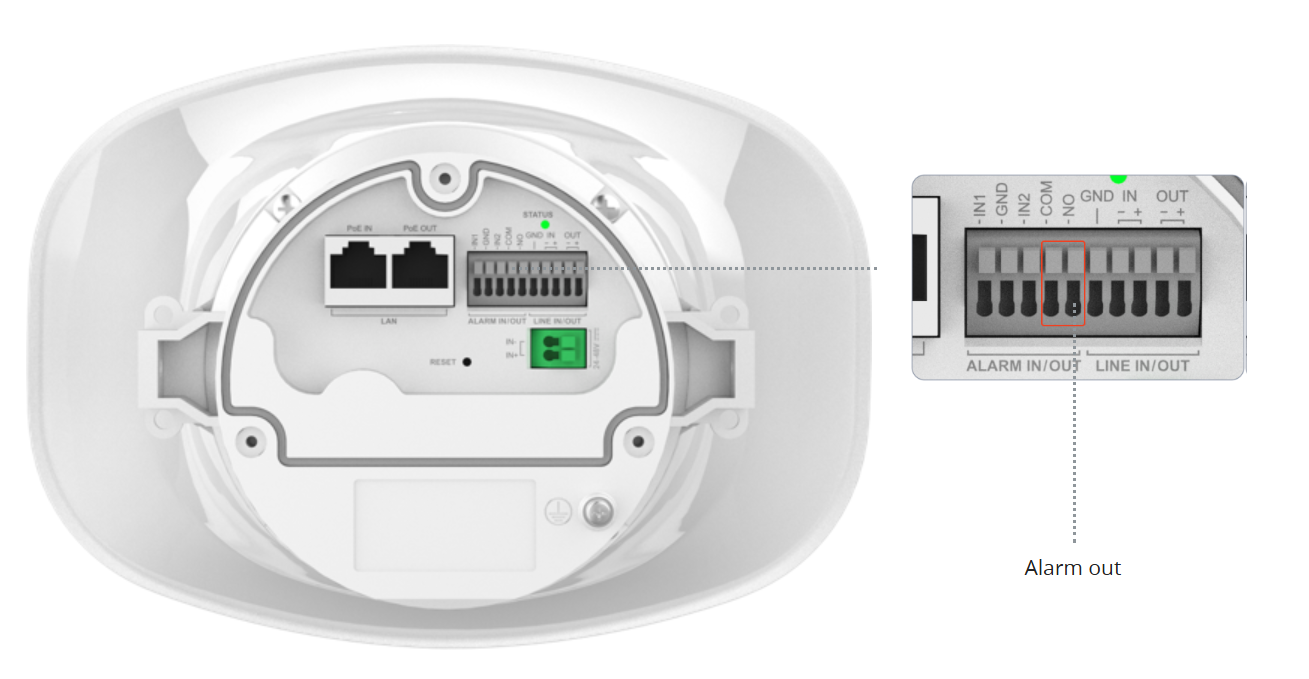
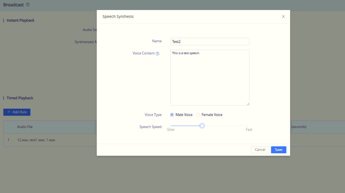
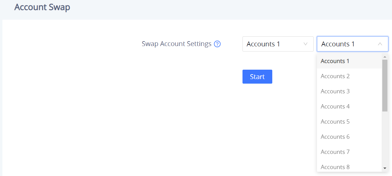



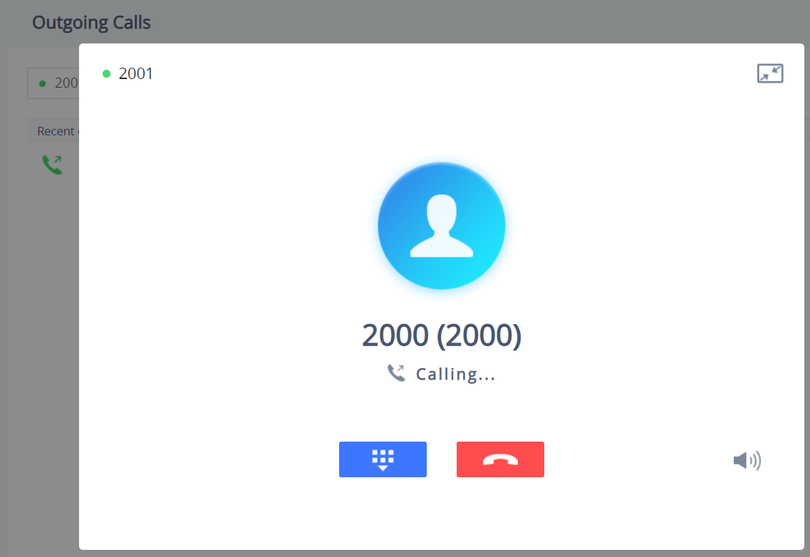
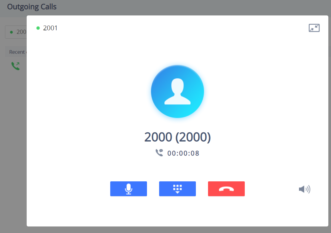
 : Reduce the window to a bar at the top of the Web GUI interface.
  : Adjust the ringing volume.
 : Mute the Mic.
  : Start recording the call.
 : End the in-progress call.
 Outgoing Calls.
 Answered Calls.
 Missed calls.


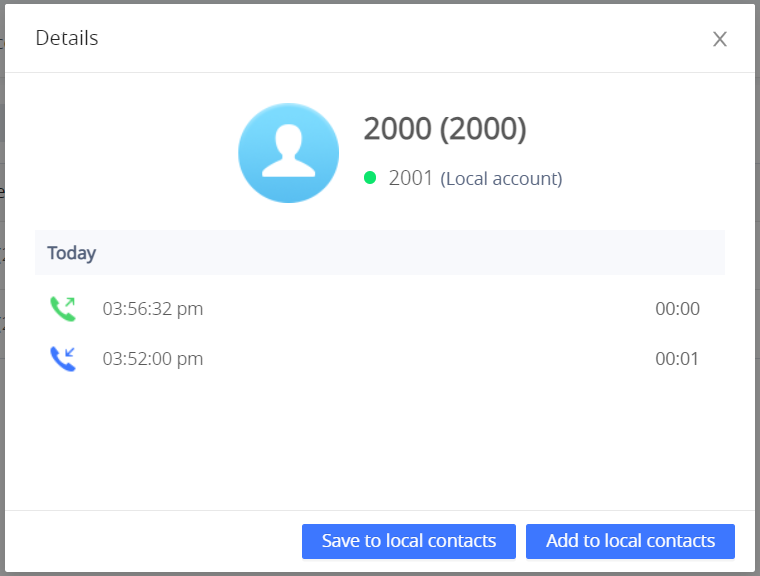
 , or by adding it to an existing contact
 .
.
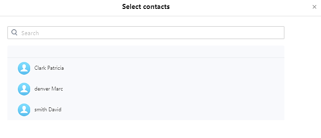
 Blocked Calls






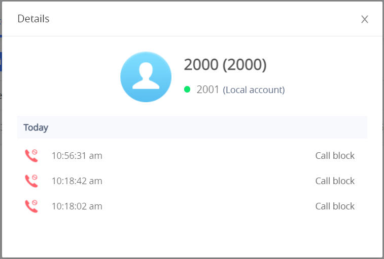
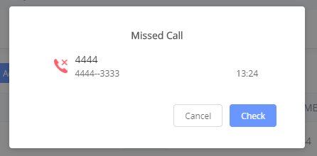

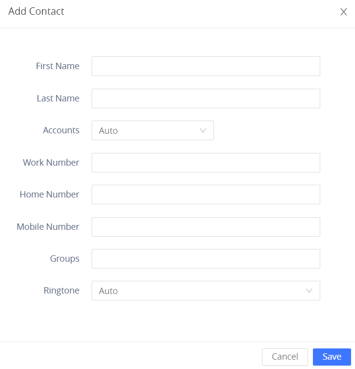
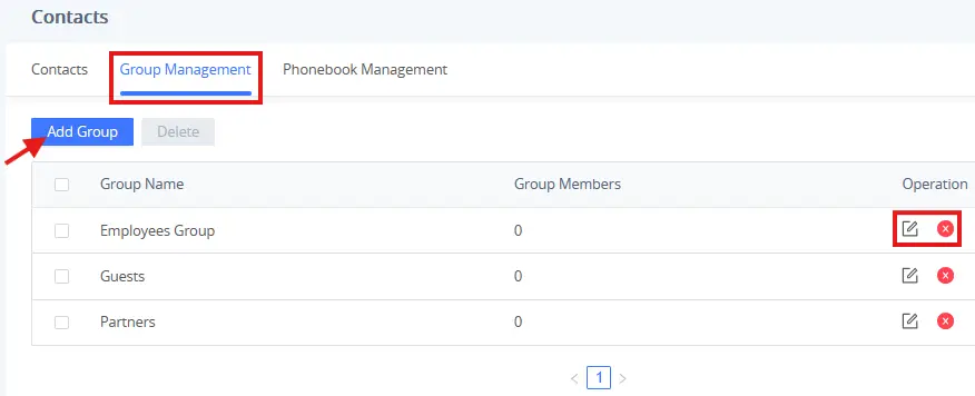
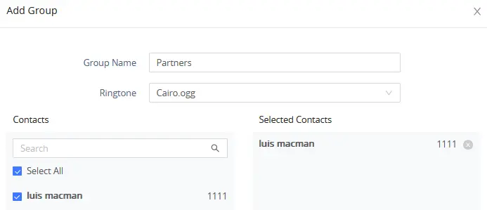
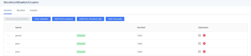
 Users can remove one or a group of numbers from the allowed list by clicking on the “Remove from Allowlist” button.
 to remove one specific contact from the allowlist.
 to remove one specific contact from the allowlist.
 Users can add the phonebook contacts to the allowlist by clicking on the “Add from contacts” button. A window pops up showing the existing contacts so that users can select the ones wishing to give permission.
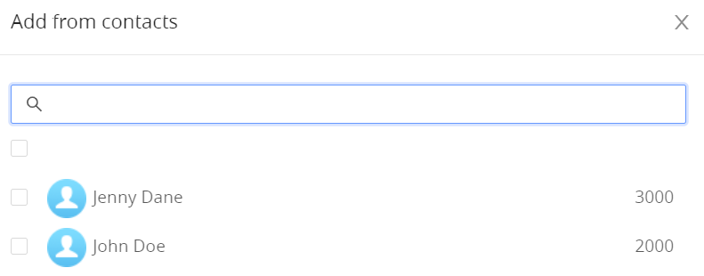
 Users can add the numbers that the GSC3518HS is blocking to the Allowlist by clicking on “Add from blocked calls”. A window pops up showing all the blocked numbers.
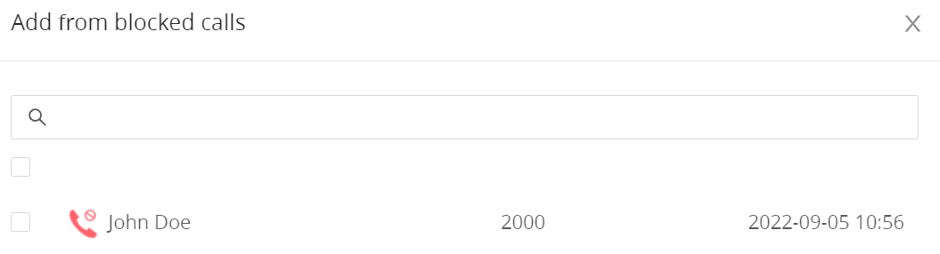
 Users can add numbers manually to the allowlist by clicking on the “Add manually” button. A window pops up, allowing users to enter the number and its name.
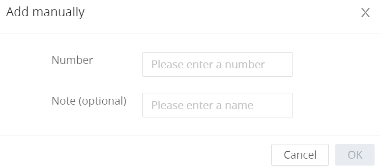
 .
. 

 to remove one specific contact from the blocklist.
 Users can add numbers from Call History to the blocklist by clicking on the “Add from call history” button. A window pops up showing all the calls listed in the GSC3518HS call history.
 Users can add phonebook contacts to the blocklist by clicking on the “Add from contacts” button. A window pops up showing the existing contacts so that users may select the ones who wish to permit.
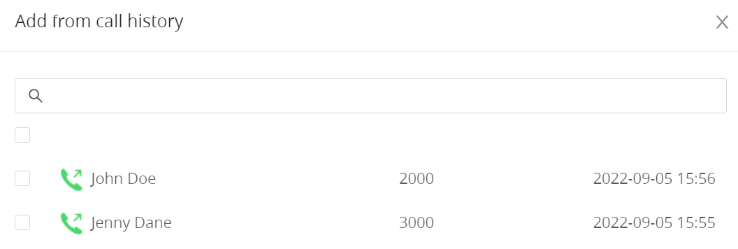

 .
.