


This guide will help you to Connect and Wire for the GSC3574/75 properly in different scenarios as listed below:
- Connection with External Access Control System
- Direct Connection to Door Lock, Doorbell, and Access Control
- Connection with Multiple Sensors and Alarms
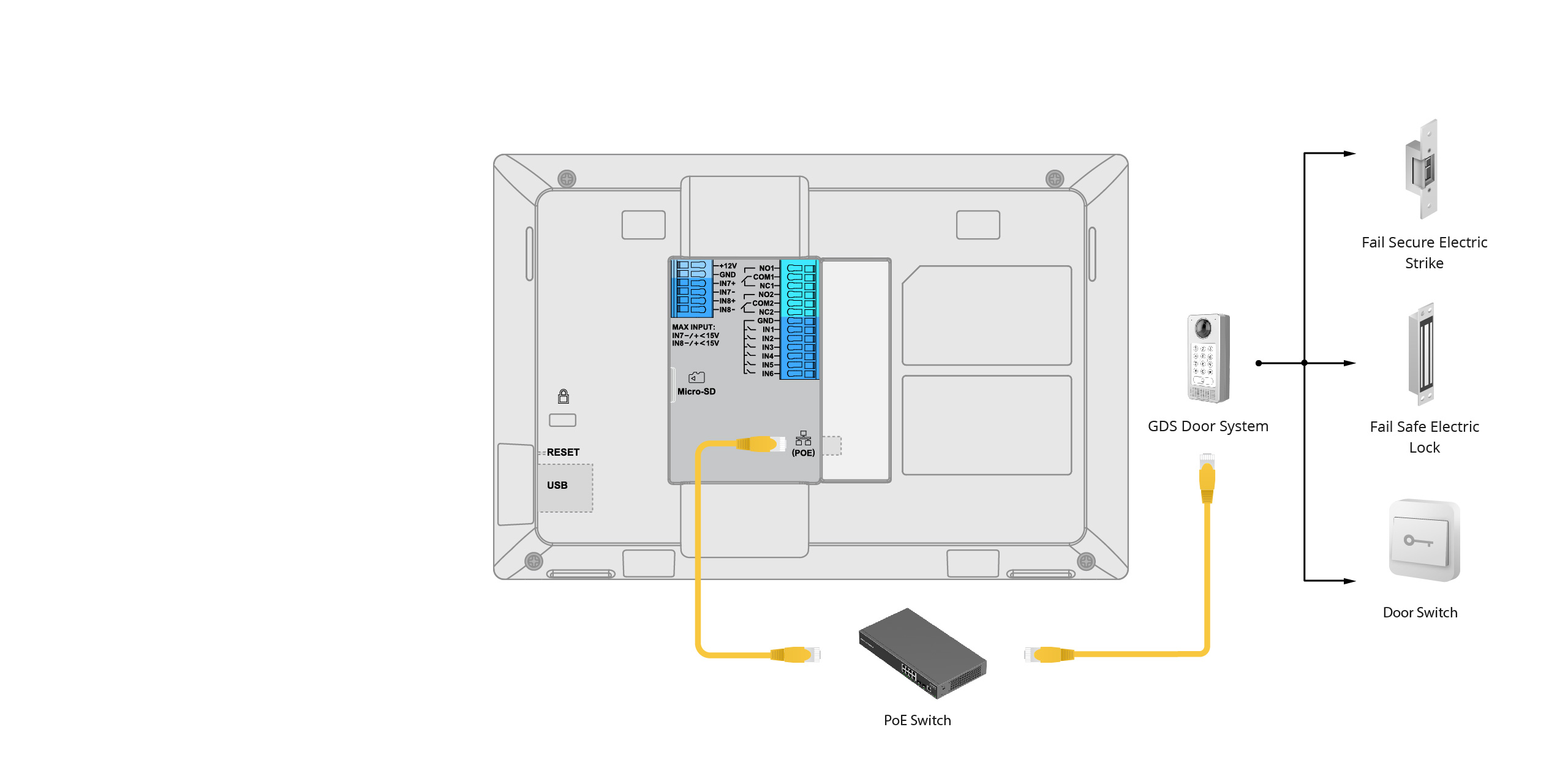
Connection with External Access Control System
In this scenario, the door locks and switches are all connected to the Door System (such as GDS37xx). GSC3574/3575 is connected to the Door System through a network.
To configure GSC3574/75 from the LCD screen go to Settings App → Advanced → Monitor → Door System.
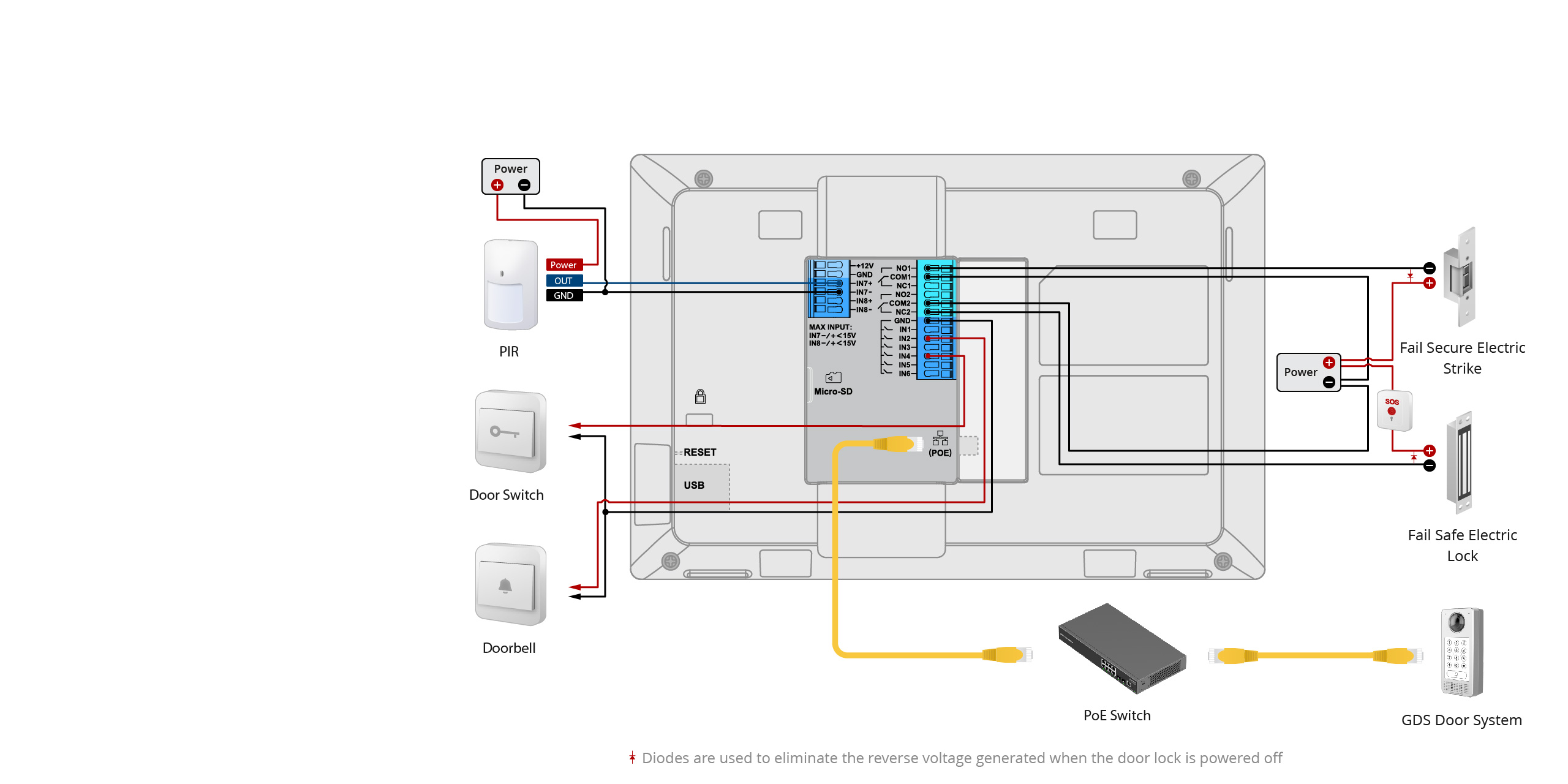
Direct Connection to Door Lock, Doorbell, and Access Control
The door lock, doorbell, and switch are connected to GSC3574/75 directly.
On the LCD Menu, access Settings App → Features → DO Settings, select the DO Mode to Open Door, and configure relevant door system information.
In the Settings App → Features → Zone Settings, select the Zone Type as Doorbell or Open Door, and configure the specific usage scenarios of doorbells and switches.
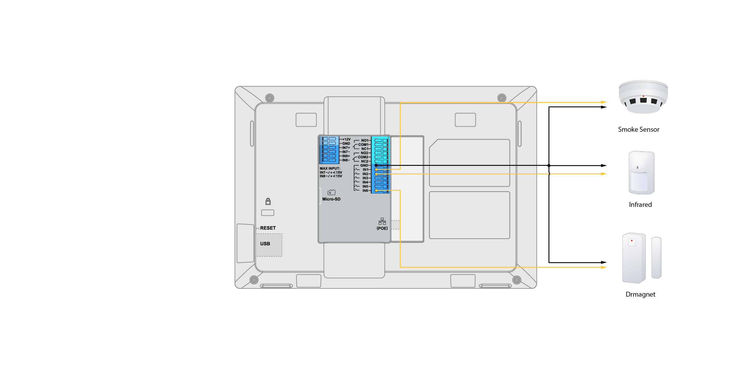
Connection with Multiple Sensors and Alarms
In this Wiring example, an infrared detector, smoke detector, gas leak detector, door open/close detector, and other sensors or alarms are connected to GSC3574/75.
In the Settings App → Features → Zone Settings, select the Zone Type as corresponding sensors, such as infrared detector, smoke detector, gas leak detector, door open/close detector, alarm, etc., and configure its specific usage scenario.
GSC3574/75 Interface table
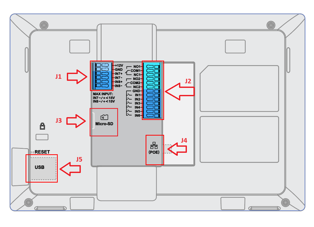
Jack | Port | Function | Remark | |
J1 | Pin | Signal | ||
1 | IN8- | Alarm IN8(Active) | Isolation type alarm input, used for voltage signal detection, IN+ connected to positive signal output of sensor, IN- connected to negative signal output of sensor or GND of sensor. The active voltage range is 9-15V. | |
2 | IN8+ | |||
3 | IN7- | Alarm IN7 (Active) | ||
4 | IN7+ | |||
5 | GND | Power Supply | DC12V recommend, input voltage rang 11-13V, current at least 1.5A@12V. | |
6 | +12V | |||
J2 | 1 | NO1 | Alarm OUT1 | Relay output, normal open or close, max 125VAC/0.5A or max 30VDC/2A. |
2 | COM1 | |||
3 | NC1 | |||
4 | NO2 | Alarm OUT2 | ||
5 | COM2 | |||
6 | NC2 | |||
7 | GND | Alarm GND | Voltage reference for IN(1/2/3/4/5/6). | |
8 | IN1 | Alarm IN1(Passive) | Alarm input, used to connect devices such as buttons/ switches/ alarm sensors. | |
9 | IN2 | Alarm IN2(Passive) | ||
10 | IN3 | Alarm IN3(Passive) | ||
11 | IN4 | Alarm IN4(Passive) | ||
12 | IN5 | Alarm IN5(Passive) | ||
13 | IN6 | Alarm IN6(Passive) | ||
J3 | Micro-SD Port | Data Storage | Support microSD/ SDHC/ SDXC, up to 512GB. | |
J4 | Network Port(PoE) | Ethernet and PoE Supply | Single 10/100Mbps network port, support 802.3 af PoE power supply. | |
J5 | USB Port | Data Exchange | The USB port can be connected to USB disk (up to 2TB) / mouse/ keyboard. The default current limit is 460mA, and user can configured it to 1000mA through the web. | |