
WELCOME
Thank you for purchasing Grandstream GVC3212 HD Video Conferencing Device. This document introduces the LCD settings, web UI settings and advanced configurations of GVC3212. To learn the basic configuration and how to use the device, please visit http://www.grandstream.com/support to download the latest “GVC3212 User Guide”.
The GVC3212 is a compact and affordable HD video conferencing endpoint for TV and desktop mounting. This device pairs with Grandstream’s IPVideoTalk Meeting plans, an online conferencing platform that allows you to host meetings that can be joined on nearly any de vice including mobile, PCs, and laptops. The GVC3212 comes equipped with integrated dual microphones that offer high quality voice pickup at up to 3-meter distance, advanced echo cancellation, and sophisticated background noise suppression. It supports Miracast and Air Play for convenient wireless content screen sha ring, allowing meeting participants to share presentations, videos, or other content directly from their PC/ Mac or Android/iOS devices without tangling cables. This easy-to-use, easy-to-deploy video conferencing end point is the ideal choice for remote workers and small offices who need a price-friendly option that still pro vides the features necessary to sustain high quality video communications.
PRODUCT OVERVIEW
Table 1: GVC3212 Technical Specifications
Parameters | Descriptions |
HDMI | |
HDMI out Resolution | Configures the output image resolution of HDMI output. Greater resolution value means higher image definition. Please select the same resolution as the output display device. The device will automatically read the resolution supported by the output display device and compare it with the resolution supported by itself. Only the resolution supported by both will be used. The device will automatically obtain the optimal resolution when it boots up for the first time. |
Screen Percent | Configures the output image size on the screen of HDMI output. The value range is 90%-100%. The default setting is 100%. |
Safety Compliances
GVC3212 complies with FCC/CE and various safety standards. GVC3212 power adapter is compliant with the UL standard. Use the universal power adapter provided with the device package only. The manufacturer’s warranty does not cover damages to the device caused by unsupported power adapters.
Warranty
If GVC3212 is purchased from a reseller, please contact the company where the device is purchased for replacement, repair or refund. If the device is purchased directly from Grandstream, please contact Grandstream Support for a RMA (Return Materials Authorization) number before the product is returned. Grandstream reserves the right to remedy warranty policy without prior notification.
GVC3212 WEB GUI SETTINGS
GVC3212 embedded Web server responds to HTTP/HTTPS GET/POST requests. Embedded HTML pages allow users to configure the application device through a Web browser such as Mozilla Firefox, Google ChromeTM, etc.
Accessing GVC3212 Web GUI
The IP address of the GVC3212 will show on the top status bar of the connected display device (e.g., TV) via HDMI
To access GVC3212 Web GUI:
- Connect the computer to the same network as GVC3212
- Make sure GVC3212 is turned on and shows its IP address on the connected display screen.
- Open a Web browser on your computer.
- Enter GVC3212’s IP address in the address bar of the browser, e.g.: http://192.168.124.111.
- Enter the administrator’s login and password to access the Web Configuration Menu. The default administrator username is “admin” and the default random password can be found at the back sticker on the GVC3212. The default end user username and password are “user” and “123”. The user can select English or other languages in the drop-down menu of language.
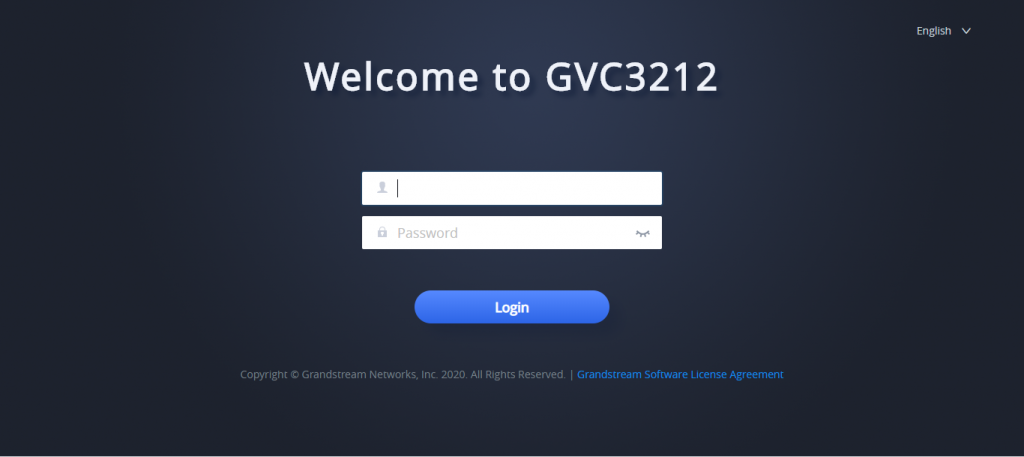
6. Click “Login” to access the configurations in web UI.
Saving Changes
When changing any settings on the web UI, always submit them by pressing the “Save” button on the bottom of the page.
Definitions
This section describes the options in the GVC3212 Web GUI. As mentioned in the previous section, you can log in as an administrator or a normal user.
- Status
Account Status, Peripheral Status, Network Status, System Info.
- Network Settings
Ethernet Settings, Wi-Fi Settings, Advanced Network Settings.
- System Settings
Power Manager, Time & Language, Security Settings, Audio Control
- Device Control
Peripheral.
- Maintenance
Upgrade, System diagnosis.
The following table shows the web pages accessible by end user and administrator.
User Type | Username | Default Password | Accessible Web Pages |
End User | User | 123 |
|
Administrator | Admin | Can be found at the back sticker | All pages |
Toolbar
The web UI tool bar is on the upper right corner of the web UI page.

- DND
Turn on/off DND mode. Once enabled, the DND text will turn into red in web UI. On the LCD display of the GVC3212 a DND Icon will be displayed in the status bar and all incoming calls will be rejected.
- Remote Control
Click to bring up virtual remote-control panel.
- English
Select the display language for the web UI.
- Logout
Log out from the web UI.
Status
The Status page lists Account Status, Peripheral Status, Network Status and System info Status.
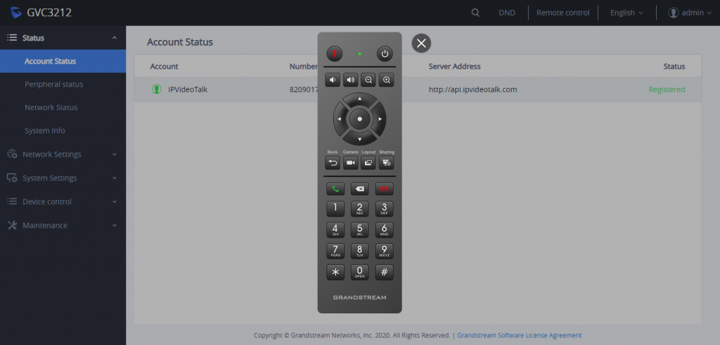
Status/Account Status
Parameters | Descriptions |
Account | IPVideoTalk Account. |
Number | IPVideoTalk Account ID. |
Server Address | IPVideoTalk server’s address. |
Status | It shows the registration status of the account: Registered or Unregistered. |
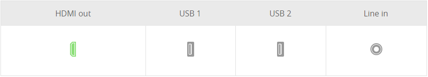
Status/Peripheral Status
This pages shows the connection status of each interface of the GVC3212. Icon in green indicates “Connected” and the icon in grey means “Not Connected”.
Status/Network Status
Parameters | Descriptions |
MAC Address | This is the global unique ID of device. |
Address Type | Displays how the device obtains IP address. It could be DHCP, Static IP or PPPoE. |
IP Address | IP Address obtained or configured on the device. |
Subnet Mask | Subnet mask obtained or configured on the device. |
Gateway | The gateway address obtained or configured on the device. |
DNS Server 1 | DNS Server 1 obtained or configured on the device. |
DNS Server 2 | DNS Server 2 obtained or configured on the device. |
Status/System Info
Parameters | Descriptions |
Product Model | Device model: GVC3212 |
Hardware Version | Device hardware version. |
Part Number | Device Part Number (PN). |
Serial Number | Serial Number of the Device. |
System Version | Device system version. This is the firmware version on the device. When upgrading firmware, this is the version number to refer to. |
Boot Version | Device boot version. |
Kernel Version | Device kernel version. |
Android™ Version | Device Android™ version 4.4.4 |
System Up Time | Device system up time since the last reboot. |
DDR Serial Number | DDR Serial number. |
Network Settings
Network Settings lists Basic Settings, Wi-Fi, and Advanced Settings.
Network Settings/Ethernet Settings
Parameters | Descriptions |
IP Mode | Allows user to select the preferred Internet Protocol whether IPv4 or IPv6. |
IPv4 | |
Address Type | Allows users to configure the appropriate network settings on the device. Users could select “DHCP”, “Static IP” or “PPPoE”. By default, it is set to “DHCP”.
|
DHCP Option 132 defines VLAN ID and DHCP Option 133 defines priority tag ID. GVC3212 supports DHCP VLAN override via DHCP Option 132 and DHCP Option 133, or encapsulated DHCP Option 132 and DHCP Option 133 in DHCP Option 43.
By default, it is set to “Encapsulated in DHCP Option 43”:
• When set to “Encapsulated in DHCP Option 43”, the GVC3212 will get VLAN ID and VLAN priority value from the DHCP Option 43 which has DHCP Option 132 and DHCP Option 133 encapsulated. In this case, please make sure the option “Allow DHCP Option 43 and Option 66 to Override Server” is enabled. | |
Host name (Option 12) | It is used to configure the name of the client in the DHCP request. It is optional but may be required by some Internet Service Providers. |
Vendor Class ID (Option 60) | It is used to configure the vendor class ID header in the DHCP request. The default setting is “Grandstream GVC3212”. |
Layer 2 QoS 802.1q/VLAN Tag (Ethernet) | It is used to define the VLAN Identifier of the Layer 2 frames. The default value 0 which means the frame does not belong to any VLAN. Note: Please do not change the setting before understanding the VLAN’s settings. Otherwise the device cannot get the correct IP address. |
Layer 2 QoS 802.1p Priority value (Ethernet) | It is used to define the Priority Code Point within a Layer 2 frame header. The valid range from 0 to 7. The Default value is 0 which is equivalent to the Routine class for the Class of Service. |
IP Address | It is used to configure the device’s static IP address if the static IP is used. |
Subnet Mask | It is used to configure the network’s subnet mask if the static IP is used. |
Gateway | It is used to configure the network’s gateway address if the static IP is used. |
DNS Server 1 | It is used to configure the primary DNS IP address if the static IP is used. |
DNS Server 2 | It is used to configure the secondary DNS IP address if the static IP is used. |
PPPoE Account | It is used to configure the PPPoE account ID if the PPPoE is used. |
PPPoE Password | It is used to configure the PPPoE password if the PPPoE is used. |
IPv6 | |
IPv6 Address | Allows users to choose whether to get automatically the IPv6 address from DHCP server (Auto-configured) or configure a static IPv6 address (Statically configured). Default is Auto configured. |
Preferred DNS Server | Enter the Preferred DNS server. |
Static IPv6 Address | It is used to configure a static IPv6 address if Statically configured is used. |
IPv6 Prefix Length | It is used to set the IPv6 prefix length if Statically configured is used. Default is 64. |
DNS Server 1 | It is used to configure the primary DNS IP address if Statically configured is used. |
DNS Server 2 | It is used to configure the secondary DNS IP address if Statically configured is used. |
Preferred DNS Server | It is used to configure the preferred DNS server. |
802.1x Mode | |
802.1x Mode | It is used to enable and select the 802.1x mode for the device. The supported 802.1x modes are:
The default setting is “Disable”. |
802.1x Identity | It is used to fill in the identity information for the selected 802.1x mode. This setting will be displayed only if 802.1x mode is enabled. |
802.1x Secret | It is used to enter the secret for the 802.1x mode. This setting will be displayed only if the 802.1x mode is enabled. |
Private Key | It is used to enter the private key password for the 802.1x mode. This setting will be displayed only if the 802.1x mode is enabled. |
CA Certificate | It is used to upload the CA Certificate file to the device. This setting will be displayed only if the 802.1x mode is enabled. |
Client Certificate | It is used to load the Client Certificate file to the device. This setting will be displayed only if the 802.1x TLS mode is enabled. |
Network Settings/Wi-Fi Settings
Parameters | Descriptions |
WiFi Basics | |
Wi-Fi Function | This parameter enables/disables the Wi-Fi function. The default setting is set to “No” |
ESSID | This parameter sets the ESSID for the wireless network. Press “Scan” to scan for the available wireless network. The number in brackets represents the signal intensity. |
ESSID | Enter the ESSID name. |
Security Mode For Hidden SSID | This parameter defines the security mode used for the wireless network when the SSID is hidden. |
Advanced Settings | |
Layer 2 QoS 802.1p Priority Value (WiFi) | Assigns the priority value of Layer 2 QoS packets for WiFi. |
Country Code | Configure Wi-Fi country code. The default value is “US”. This setting requires reboot to take effect. |
Host Name (Option 12) | Specifies the name of the client. This field is optional but may be required by some Internet Service Providers. |
Vendor Class ID (Option 60) | Used by clients and servers to exchange vendor class ID. |
Network Settings/Advanced Settings
Advanced Network Settings | |
Preferred DNS 1 | Configures the preferred DNS 1 address. |
Preferred DNS 2 | Configures the preferred DNS 2 address. |
Enable LLDP | It is used to enable the LLDP (Link Layer Discovery Protocol) feature on the device. If it is set to “Yes”, the device will broadcast LLDP PDU to advertise its identity and capabilities and receive same from a physical adjacent layer 2 peer. The default setting is “Yes”. |
LLDP TX Interval(s) | Configures the interval the phone sends LLDP-MED packets. Default is 30 |
Enable CDP | Configures whether to enable CDP to receive and/or transmit information from/to CDP-enabled devices. Default is Enabled. |
Layer 3 QoS for SIP | This field defines the layer 3 QoS parameter for SIP packets. This value is used for IP Precedence, Diff-Serv or MPLS. The default setting is 26. |
Layer 3 QoS for Audio | Defines the Layer 3 QoS parameter for audio packets. This value is used for IP Precedence, Diff-Serv or MPLS. The default setting is 46. |
Layer 3 QoS for Video | Defines the Layer 3 QoS parameter for video packets. This value is used for IP Precedence, Diff-Serv or MPLS. The default setting is 34. |
HTTP/HTTPS User-agent | This sets the user-agent for HTTP/HTTPS request. |
SIP User-agent | This sets the user-agent for SIP. If the value includes word “$version”, will replace it with the real system version. Default is “Grandstream GVC3212 $version”. |
HTTP/HTTPS Proxy Hostname | It is used to configure the HTTP/HTTPS proxy URI of the network. Some of networks require going through a proxy to access to the Internet. The default setting is keeping this field blank. |
HTTP/HTTPS Proxy Port | It is used to configure the HTTP/HTTPS proxy port number of the network. Some of networks require going through a proxy to access to the Internet. The default setting is keeping this field blank. |
Bypass Proxy For | It is used to define the specific URI that the device can directly access to without HTTP/HTTPS proxy. If it is filled, the device will bypass the proxy to send the packets to the specific URI. The default setting is keeping this filed blank. |
System Settings
System Settings lists Power Manager, Time & Date, Security Settings, and Audio Control
System Settings/Power Manager
Parameters | Descriptions |
Auto Sleep Timeout | Configures timeout in minutes for sleep mode. If set to “Never”, the device will not go to sleep mode automatically. |
Reboot | Press on Reboot to restart the device. |
Sleep | Press on Sleep to set the device to sleep mode. |
Shutdown | Press on Shutdown to turn off the device. |
System Settings/Time & Language
Parameters | Descriptions |
Time Settings | |
NTP Server | Defines the URL or IP address of the NTP server. The device may obtain the date and time from the server. The default setting is “pool.ntp.org”. |
DHCP Option 42 Override NTP Server | It is used to set if the device will allow the DHCP offer overrides the NTP server address setting. If it set to “Yes”, the DHCP offer with Option 42 will override the device’s NTP server address setting. The default setting is “Yes”. |
DHCP Option 2 to Override Time Zone Setting | It is used to set if the device will allow the DHCP offer overrides the Time Zone setting. If it set to “Yes”, the DHCP offer with Option 2 will override the device’s time zone setting. The default setting is “No”. |
Time zone | It is used to set the local time zone for the device. It covers the global time zones and user can selected the specific one from the drop-down list. |
Time Display Format | Check/uncheck to display the time using 24-hour time format or not. For example, in 24-hour format, 13:00 will be displayed instead of 1:00 pm. The default setting is “Yes”. |
Date Display Format | It is used to set the format used to display the date. It can be selected from the drop-down list. The default setting is MM/DD/YYYY.
|
Language | |
Language | Select the language from the drop-down menu. |
Select Language File | Press “Browse” to bring up a file selection menu to select the local .txt file to upload to the device. |
System Settings/Security Settings
Parameters | Descriptions |
Web/SSH Access | |
Enable SSH | If set to “Yes”, the device will allow any SSH access to the device. Default setting is enabled. |
SSH Port | Configures the SSH port. Default is 22. |
Access Method | It is used to set which protocol will be used to access the device’s Web GUI. It can be selected from HTTP and HTTPS. The default setting is HTTP. |
Port | It is used to set which port will be used to access the device’s Web GUI. By default, if HTTP is selected, the port number will be 80; if HTTPS is selected, the port number will be 443. |
User Info Management | |
Current Admin Password | Enters current logged-in user’s password. This field is case sensitive. |
New Admin Password | Allows the user to change the admin password. The password field is purposely blank after clicking the “Save” button for security purpose. This field is case sensitive with a maximum length of 32 characters. |
Confirm New Admin Password | Enters the new admin password again to confirm. |
New User Password | Allows the administrator to set the password for user-level web GUI access. This field is case sensitive with a maximum length of 32 characters. |
Confirm New User Password | Enter the new user password again to confirm. |
Import Trusted CA Certificates | Allows to upload the ca certificate file to phone. |
Trusted CA Certificates | Lists trusted ca certificates previously uploaded. Administrator can delete a certificate from here. |
Add User Certificate | Allows to upload & Install user certificate file to phone |
Certificate Application | Specifies on which application, the user certificate will be applied. Administrator can select either “Wi-Fi” or “other applications”. |
Select Certificate | Browse your computer and upload the user certificate. |
Certificate Name | Enter a name to identify the user certificate. |
User Certificates | Lists user certificates previously uploaded. Administrator can delete a certificate from here. |
Import Custom Certificates | Allows to upload the custom certificate file to phone. |
Custom Certificate | Lists custom certificates previously uploaded. Administrator can delete a certificate from here. |
System Settings/Audio Control
Device Control
Device Control section allow users to configure the device’s HDMI settings.
Device Control/Peripheral
Parameters | Descriptions |
HDMI | |
HDMI out Resolution | Configures the output image resolution of HDMI output. Greater resolution value means higher image definition. Please select the same resolution as the output display device. The device will automatically read the resolution supported by the output display device and compare it with the resolution supported by itself. Only the resolution supported by both will be used. The device will automatically obtain the optimal resolution when it boots up for the first time. |
Screen Percent | Configures the output image size on the screen of HDMI output. The value range is 90%-100%. The default setting is 100%. |
Maintenance
Maintenance section lists Upgrade, System Diagnosis.
Maintenance/Upgrade
Parameters | Descriptions |
Upgrade Via Manually Upload | |
Complete Upgrade |
For example: if the device cannot fully boot-up but the user still login web UI, please enable this feature to recover the system. |
Upload Firmware File to Update | Manually upload firmware file from PC to the device system directly. |
Upgrade Via Network | |
Firmware Upgrade Mode | It is used to set the upgrading protocol for the device to retrieve firmware file. It can be selected from TFTP, HTTP and HTTPS. The default setting is HTTP. |
Firmware Server Path | It is used to define the server path for upgrading the firmware. It can be different from the Config Server Path. Default setting is “fw.ipvideotalk.com/gvc3212”. |
HTTP/HTTPS Username | It is used to type the username for the HTTP/HTTPS server authentication for firmware server. |
HTTP/HTTPS Password | It is used to type the password for the HTTP/HTTPS server authentication for firmware server. |
Firmware File Prefix | It is used to set the prefix characters for the firmware files. If it is configured, only the firmware with the matching encrypted prefix will be downloaded and flashed into the device system. It allows the ITSP to lock firmware updates. |
Firmware File Postfix | It is used to set the post characters for the firmware files. If it is configured, only the firmware with the matching encrypted postfix will be downloaded and flashed into the device system. It allows the ITSP to lock firmware updates. |
Download Device Configuration | It is used to download the device configuration file in text format. The config file includes all the P value parameters for device’s current settings except password for security purpose. |
Upload Device Configuration | It is used to upload the configuration file to the device. |
Use Grandstream GAPS | It is used to configure the download path and update mode for the configuration file server. If set to “Yes”, the GVC3212 will set the download path of the configuration file to fm.grandstream.com/gs by default, and use HTTPS protocol to connect to the server. If set to “No”, users can manually configure the path and update mode to retrieve the configuration file. |
Config Upgrade Via | When “Use Grandstream GAPS” is set to “No”, users can use this option to set the provisioning protocol for the device to retrieve the config file. It can be selected from TFTP, HTTP and HTTPS. The default setting is HTTPS. |
Config Server Path | When “Use Grandstream GAPS” is set to “No”, users can use this field to define the server path for provisioning the configuration file. It can be different from the Firmware Server Path. Default setting is “fm.grandstream.com/gs”. |
HTTP/HTTPS Username | It is used to type the username for the HTTP/HTTPS server authentication for config server. |
HTTP/HTTPS Password | It is used to type the password for the HTTP/HTTPS server authentication for config server. |
Always send HTTP Basic Authentication Information | It is used to set if the device includes the credential information in the HTTP/HTTPS request messages to download the cfg.xml file. If it is set to “Yes “, the credential information will always be included in the HTTP/HTTPS messages regardless the server’s challenge. The default setting is “No”. |
Config File Prefix | It is used to set the prefix characters for the configuration files. If it is configured, only the firmware with the matching encrypted prefix will be downloaded and flashed into the device system. |
XML Config File Password | The password for encrypting the XML configuration file using OpenSSL. The password is to decrypt the XML configuration file if it is encrypted via OpenSSL. |
Provision | |
Automatic Upgrade | |
Automatic Upgrade | Specifies when the firmware upgrade process will be initiated; there are 4 options: • No: The phone will only do upgrade once at boot up. • Check every day: User needs to specify “Hour of the day (0-23)”. • Check every week: User needs to specify “Hour of the day (0-23)” and “Day of the week (0-6)”. • Check Every Interval: User need to specify the time period to check for firmware upgrade (in minutes) and specify “Hour of the day (0-23)” Note: Day of week is starting from Sunday. The default setting is “No”. |
Enable Randomized Automatic Upgrade | Setting whether to upgrade automatically at random. It means whether the device will upgrade automatically at random time point in the setting period. This option is mainly used for multiple devices upgrade at the same time. |
Automatic Upgrade Check interval (m) | Defines the hour of the day (0-23) to check the HTTP/TFTP server for firmware upgrades or configuration files changes. This option is available when “Automatic Upgrade” is set to “Check Every Interval “. The default setting is “10080”. |
Firmware Upgrade and Provisioning | It is used to define the rules for automatic upgrade on the device. It can be selected from the following:
|
Upgrade With Prompt | If set to “No”, the device will automatically start upgrading after downloading the firmware files. Otherwise, users would need to confirm in the prompted message before upgrading process is started. The default value is “Yes”. |
DHCP option | |
Allow DHCP Option 43, 160 and 66 to Override Server | If set to “Yes” on the LAN side, the device will reset the CPE, upgrade, network VLAN tag and priority configuration according to option 43 sent by the server. At the same time, the upgrade mode and server path of the configuration upgrade mode will be reset according to option 160 and 66 sent by the server. If set to “Prefer, fallback when failed”, the device can fallback to use the configured provisioning server under its Firmware and Config server path in case the server from DHCP Option fails. |
Config Provision | |
Download and Process All Available Config Files | By default, the device will provision the first available config in the order of cfgMAC, cfgMAC.xml, cfgMODEL.xml, and cfg.xml(corresponding to device specific, model specific, and global configs). If set to “Yes”, the device will download and apply (override) all available configs in the order of cfgMAC, cfgMAC.xml, cfgMODEL.xml, cfg.xml. |
Config Provision | Device will download the configuration files and provision by the order you set. |
Advanced Settings | |
Validate Server Certificate | It is used to configure whether to validate the server certificate when download the firmware/config file. If set to “Yes”, the device will download the firmware/config file only from the legitimate server. The default setting is “No”. |
Allow AutoConfig Service Access | Set to allow access to the AutoConfig service. If not checked, access to service.ipvideotalk.com will be disabled. |
mDNS Override Server | It is used to set if the device will broadcast the Multicast DNS (mDNS) message during booting up to allow itself to be discovered and be configured by the SIP platform. If it is set to “User Type A’, the device will broadcast the MDNS message “A_grandstream-cfg.local”; if it is set to “Use Type SRV”, the MDNS message will be “SRV_grandstream-cfg.local”. The default setting is “Use Type A”. |
Factory Reset | Restore to factory default settings. Note: Please backup the data to avoid data loss. |
Maintenance/System Diagnosis
Syslog | |
Select the transport protocol over which log messages will be carried.
| |
Syslog Server | Configures the URI which the phone system will send the syslog messages to. The default setting is “log.ipvideotalk.com”. |
Syslog Level | Selects the level of logging for syslog. The default setting is “None”. There are 4 levels from the dropdown list: DEBUG, INFO, WARNING and ERROR. The following information will be included in the syslog packet:
Note: Changing syslog level does not require a reboot to take effect. |
Syslog Keyword Filter | Only send the syslog with keyword, multiple keywords are separated by comma. Example: set the filter keyword to “SIP” to filter SIP log. |
Clear Log | Clears the log files saved in the phone system. |
Log Tag | Configures the filter to display the specified process log file. |
Log Priority | Selects the log priority to display. It can be selected from list below:
|
Debug | |
One-click Debugging | |
One-click Debugging | Capture the checked info in the debugging list, click “Start” to debug if including “Capture trace” item and click “Stop” to end, Click “Capture” in another situation. All retrieved files will be generated to a package, and the last package will be overwritten, while the trace file will stay remain. |
Debug Info Menu | Display a list of info items that can be debugged, currently supports system logs, info log, capture package, tombstones and ANR log. The captured data can be viewed in “Debug information list”. The default is all selected. |
Debug Info List | You can select the existing debugging info package or grab package. Click the “Delete” button on the right to delete the file. |
View Debug Info | You can select the existing debugging info package or grab package. Click the “Delete” button on the right to delete the file. |
Core Dump | |
Enable Core Dump Generation | Configures whether to generate and save the core dump file when the program crashes. The default setting is “No”. |
Core Dump List | Selects the existing core dump file in the drop-down box. Users could delete the file by pressing on “Delete” button. |
View Core Dump | Press “List” button to view all existing core dump files. The files are listed in chronological order, users could click the file name to download the file to the local computer. |
Record | |
Record | Click to start capturing audio data, click the “Stop” button to end. To capture the audio data of the device can help to locate audio issues. The default is not enabled. You can record up to 1-minute audio data. |
Recording List | Choose the existing audio file. Click the “Delete” button on the right to delete this file. |
View Recording | Click on the “List” button to view. The captured audio data will be sorted by time. Click to download the data to the computer for analysis. Note: The audio data file will be saved under FileManager 🡪 Internal Storage 🡪 Recfiles folder. Users can also delete files under this folder. |
Traceroute | |
Target Host | The IP address or URL for the Target Host of the Traceroute. Press Start to send traceroute request to configured target host. Press Stop to end traceroute running process. |
Ping | |
Target Host | The IP address or URL for the Target Host of the ping. Press Start to send ping request to configured target host. Press Stop to end ping running process. |
NSLookup | |
Hostname | Enter a host name and find out the corresponding IP address. It will also do reverse name lookup and find the host name for an IP address you specify |
FIRMWARE UPGRADE
GVC3212 supports software upgrade via the following methods:
- Manually upload firmware file to upgrade (for applicable firmware versions only).
- Upgrade via TFTP firmware server
- Upgrade via HTTP/HTTPS firmware server
No Local TFTP/HTTP Servers
Service providers should maintain their own firmware upgrade servers. For users who do not have a TFTP/HTTP/HTTPS server, some free Windows version TFTP servers are available for download from:
http://www.solarwinds.com/products/freetools/free_tftp_server.aspx
Please check our website at http://www.grandstream.com/support/firmware for latest firmware.
Upgrade GVC3212 via TFTP Server
Here is the instruction to upgrade GVC3212 via TFTP server:
- Unzip the firmware files and put all of them in the root directory of the TFTP server.
- Connect the PC running the TFTP server and the GVC3212 device to the same LAN segment.
- Launch the TFTP server and go to the File menu🡪Configure🡪Security to change the TFTP server’s default setting from “Receive Only” to “Transmit Only” for the firmware upgrade. (This step may be different depending on the TFTP server software you are using).
- Start the TFTP server.
- On the GVC3212 web UI🡪Maintenance🡪Upgrade page, configure TFTP as the “Firmware upgrade mode” and enter the IP address of the PC in “Firmware server path” field.
- Save and apply the change. Then reboot the device.
Please note end users can also choose to download a free HTTP server from http://httpd.apache.org/ or use Microsoft IIS web server.
Provisioning and Configuration File Download
Grandstream SIP Devices can be configured via the Web Interface as well as via a Configuration File (binary or XML) through TFTP or HTTP/HTTPS. The “Config Server Path” is the TFTP, HTTP or HTTPS server path for the configuration file. It needs to be set to a valid URL, either in FQDN or IP address format. The “Config Server Path” can be the same or different from the “Firmware Server Path”. A configuration parameter is associated with each particular field on the web configuration page. A parameter consists of a Capital letter P and 2 to 4-digit numeric numbers. i.e., P2 is associated with the “Admin Password” in the Web GUI🡪Security Settings 🡪 User Info Management page. For a detailed parameter list, please refer to the corresponding firmware release configuration template in the following link: http://www.grandstream.com/support/tools
When the GVC3212 boots up, it will issue TFTP or HTTP request to download a configuration XML file named “cfgxxxxxxxxxxxx” followed by “cfgxxxxxxxxxxxx.xml”, where “xxxxxxxxxxxx” is the MAC address of the device, i.e., “cfg000b820102ab” or “cfg000b820102ab.xml”. If downloading “cfgxxxxxxxxxxxx.xml” file is not successful, the provision program will download a generic cfg.xml file. The configuration file name should be in lower case letters.
For more details on XML provisioning, please refer to the following document:
https://documentation.grandstream.com/knowledge-base/sip-device-provisioning-guide/
Users could find XML configuration file generator tool and user guide in the following web page. Please use the XML configuration file generator to generate the XML configuration file for your devices’ provisioning.
http://www.grandstream.com/support/tools
FACTORY RESET
Users could reset GVC3212 to factory settings via the following ways:
- Reset via LCD menu
- Reset via GVC3212 web UI
- Reset via the reset pin hole on the back panel of GVC3212.
Factory reset will delete configuration information and syslog information.
Reset via LCD Menu
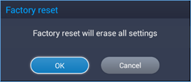
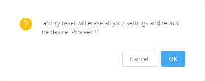
Go to GVC3212 LCD idle screen 🡺 Settings 🡺 Advance 🡺 Factory Reset, click on the “Reset” button to bring up the prompt box as shown below. Click “OK” to reboot the device and restore factory settings.
Reset via Web UI
- Log in GVC3212 Web UI 🡺 Maintenance 🡺 Upgrade 🡺 Advanced Settings, the “Factory Reset” option is on the bottom of the page.

2. Click the “Reset” button to bring up the prompt box as shown below. Click “OK” to reboot the device and restore factory settings.
Reset via Reset Pin Hole
There is a Reset pin hole on the back panel of GVC3212. To reset the device, use a small pin to hold against the Reset pin hole for more than 10 seconds to restore to factory settings.
EXPERIENCING THE GVC3212
Please visit our website: http://www.grandstream.com to receive the most up-to-date updates on firmware releases, additional features, FAQs, documentation and news on new products.
We encourage you to browse our product related documentation, FAQs and User and Developer Forum for answers to your general questions. If you have purchased our products through a Grandstream Certified Partner or Reseller, please contact them directly for immediate support.
Our technical support staff is trained and ready to answer all of your questions. Contact a technical support member or submit a trouble ticket online to receive in-depth support.
Thank you again for purchasing Grandstream Video Conferencing System, it will be sure to bring convenience and color to both your business and personal life.
——————————————————————————————————————————————–
* Android is a trademark of Google Inc.
HDMI, the HDMI Logo, and High-Definition Multimedia Interface are trademarks or registered
trademarks of HDMI Licensing LLC in the United States and other countries.
——————————————————————————————————————————————–
CHANGE LOG
This section documents significant changes from previous versions of the GVC3212 user manuals. Only major new features or major document updates are listed here. Minor updates for corrections or editing are not documented here.
Firmware Version 1.0.1.6
- No major changes.
Firmware Version 1.0.0.6
- This is the initial version.