
WELCOME
Thank you for purchasing Grandstream GVC3200/GVC3202 AndroidTM Video Conferencing System. This document introduces the LCD settings, web UI settings and advanced configurations of GVC3200/GVC3202. To learn the basic configuration and how to use GVC3200/GVC3202, please visit http://www.grandstream.com/support to download the latest “GVC3200/GVC3202 User Guide”.
GVC3200/GVC3202 is a ground-breaking solution that offers small-to-medium businesses a revolutionary video conferencing system with unprecedented flexibility and the power of support for multiple popular video conferencing protocols and platforms right out of the box. The SIP-based GVC3200/GVC3202 supports Grandstream’ s robust IPVideoTalk cloud platform for plug and play video conferencing.
The GVC3200/GVC3202 sports an innovative, patent-pending embedded MCU that supports conferencing with local mixing between SIP, H.323 and Android applications.
- The GVC3200 supports 9-way conferencing with local mixing between SIP, H.323 and Android applications.
- The GVC3202 supports 3-way conferencing with local mixing between SIP, H.323 and Android applications.
In comparison to Grandstream’s GVC3200, the GVC3202 offers a slightly lower capacity option for businesses looking for up to 3-way video-conferencing and support for up to 2 Full HD monitors.
The GVC3200/GVC3202 eliminates the traditional barriers to video conferencing and sets a new bar for business-class video conferencing solutions by offering industry-leading flexibility, interoperability, system compatibility, application richness and ease of use.
PRODUCT OVERVIEW
Specification | Description |
Protocols/ Standards | SIP RFC3261, BFCP, TIP (pending), RTP/RTCP, HTTP/HTTPS, ARP, ICMP, DNS (A record, SRV, NAPTR), DHCP, PPPoE, SSH, TFTP, NTP, STUN, LLDP-MED, LDAP, TR-069, 802.1x, TLS, SRTP, TCP/IP/UDP, IPv6, FEC, FECC, H.323, Q.931, H.224, H.281, H.225.0, H.239, H.241, H.245, H.460.18 and H.460.19 |
Camera | 1/3” 2 Megapixel CMOS 1920H x 1080V@30fps |
Lens | GVC3200: 12 x optical zoom, +/-23° tilt, +/- 90° pan, 70°(W)*- 6.3° (T) field of view GVC3202: 9 x optical zoom, +/-23° tilt, +/- 90° pan, 70°(W)*- 6.3° (T) field of view |
Network Interface | 1 x RJ45 10/ 100/ 1000 Mbps port |
Wi-Fi | GVC3200 only: Integrated dual-band 802.11 a/b/g/n (2.4GHz & 5GHz) |
Bluetooth | Yes, integrated Bluetooth |
Video Outputs | GVC3200: 3 x HDMI up to 1080p with CEC / GVC3202: 2 x HDMI up to 1080p with CEC |
Video Input | 1 x VGA/1 x HDMI with resolution up to 1080p |
Microphone/ Speaker | External MIC/Speaker, built-in MIC, cascadable external MIC/speaker (pending) |
Remote Control | Bluetooth remote control with multi-touch touchpad |
Auxiliary Ports | 1 x USB 2.0, SD, external speaker port, reset pin |
Graphic Display | OLED with 128×32 resolution |
G.711μ/a, G.722 (wide-band), iLBC (pending), Opus, G.722.1, G.722.1c (pending), in-band and out-of-band DTMF (In audio, RFC2833, SIP INFO) | |
Video Codecs | H.264 BP/MP/HP, H.323, video resolution up to 1080p, frame rate up to 30fps, bitrate up to 4Mbps |
People Video Resolution | 1080p from 512 Kbps, 720p from 384 Kbps, 4SIF/4CIF from 128 Kbps, SIF/CIF/QSIF/QCIF/SQSIF/SQCIF from 64 Kbps |
Content Video Resolution | Input: VGA, SVGA, XGA, WXGA, WXGA, SXGA, 1440×900, 720p, 1600×1200, 1080p (HDMI), up to 60fps; Encoding: 1280×720, 1920×1080 |
Output Resolution | 720p, 1080p |
Embedded MCU | GVC3200: Up to 4-way 1080p conference, 5-way 720p conference, 9-way VGA conference GVC3202: Up to 2-way 1080p conference, 3-way 720p conference, 3-way VGA conference |
Dual-Stream | BFCP, people video (up to 1080p@30fps) + content video (up to 1080p@15fps, 720p@30fps) |
Audio Features | AEC, ANS, AGC, PLC, CNG/VAD |
Video Features | FEC, dynamic display layout, picture-in-picture, picture-outside-picture, digital caption (pending) |
Platform Bridging | Bridge SIP calls with any Android VoIP apps. |
Telephony Features | Hold, transfer, forward (unconditional/no-answer/busy), call park/pickup, 9-way audio/video conference for GVC3200 and 3-way audio/video conference for GVC3202, downloadable XML phone book, LDAP, call waiting, call history, flexible dial plan, personalized music ringtones, server redundancy & fail-over |
Sample Applications | Web browser, Facebook, Twitter, YouTube, Google calendar, mobile phone data import/export via Bluetooth, etc. API/SDK available for advanced custom application development |
Application Deployment | Allows Android 4.4.2 compliant applications to be deployed in the device with provisioning control |
QoS | Layer 2 QoS (802.1Q, 802.1p) and Layer 3 (ToS, DiffServ, MPLS) QoS |
Security | User and administrator level passwords, MD5 and MD5-sess based authentication, 256-bit AES encrypted configuration file, TLS, 128/256-bit SRTP, HTTPS, 802.1x media access control |
Multi-Language | English, German, Italian, French, Spanish, Portuguese, Russian, Turkish, Polish, Chinese, Korean, Japanese, and more |
Upgrade/ Provisioning | Firmware upgrade via TFTP/HTTP/HTTPS or local HTTP upload, mass provisioning using TR-069 or AES encrypted XML configuration file |
Power & Green Energy Efficiency | Universal power adapter included: Input 100-240VAC 50-60Hz; Output 12VDC/5A (60W) |
Package Content | – GVC3200: GVC3200 video conference system, external USB speaker/MIC (GAC2500), remote control, universal power supply, network cable (1.5 meters), USB extension cable (5 meters), mounting kit, 4 HDMI cables (one 1.5-meter cable, two 3-meter cables and one 5-meter cable), 4 AAA batteries, lens cover, quick installation guide, brochure, GPL license – GVC3202: GVC3202 video conference system, external USB speaker/MIC (GAC2500), remote control, universal power supply, network cable (1.5 meters), USB extension cable (5 meters), mounting kit, 3 HDMI cables (one 1.5-meter cable, one 3-meter cables and one 5-meter cable), 4 AAA batteries, lens cover, quick installation guide, brochure, GPL license |
Temperature and Humidity | Operation: 0°C to 40°C, Storage: -10°C to 60°C, Humidity: 10% to 90% Non-condensing |
Compliance | FCC: Part 15 (CFR 47) Class B; UL 60950 (power adapter), Part 15C, Part 15E.407, Part 2.1091 CE: EN55022 Class B, EN55024, EN61000-3-2, EN61000-3-3, EN60950-1, EN62479, RoHS, EN301893, EN62311 RCM: AS/NZS CISPR22/24; AS/NZS 60950; AS/NZS 4268 |
Safety Compliances
GVC3200/GVC3202 complies with FCC/CE and various safety standards. GVC3200/GVC3202 power adapter is compliant with the UL standard. Use the universal power adapter provided with GVC3200/GVC3202 package only. The manufacturer’s warranty does not cover damages to the device caused by unsupported power adapters.
Warranty
If GVC3200/GVC3202 is purchased from a reseller, please contact the company where the device is purchased for replacement, repair or refund. If the device is purchased directly from Grandstream, please contact Grandstream Support for an RMA (Return Materials Authorization) number before the product is returned. Grandstream reserves the right to remedy warranty policy without prior notification.
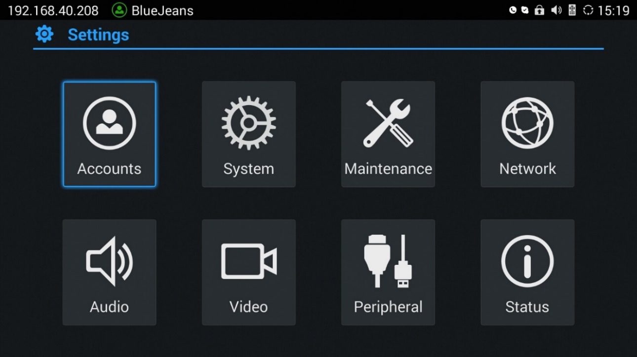
GVC3200/GVC3202 LCD SETTINGS
GVC3200/GVC3202 LCD MENU provides easy access to the Settings on the device. Most of the settings from Web UI could be configured on the local LCD settings as well.
Accounts
General
- Account
Select the account to be configured. The users can select the SIP account, the built-in BlueJeans account or H.323 account to configure here.
- Account Active
This field indicates whether the account is active. If disabled, GVC3200/GVC3202 will not send registration information to the SIP server.
- Account Name
The name associated with the account to be displayed on the upper left corner of LCD.
- SIP Server
The URL or IP address, and port of the SIP server. This is provided by your VoIP service provider (ITSP).
- SIP User ID
This is the SIP User ID provided by your VoIP service provider (ITSP). It’s usually in the form of digits similar to phone number or actually a phone number.
- SIP Authentication ID
SIP service subscriber’s Authenticate ID used for authentication. It can be identical to or different from the SIP User ID.
- SIP Authentication Password
The account password required for GVC3200/GVC3202 to authenticate with the ITSP (SIP) server before the account can be registered.
- Voice Mail Access Number
This parameter allows you to access voice messages by entering voice mailbox or dialing access number.
- Display Name
This is the SIP server subscriber’s name (optional) that will be used for Caller ID display. This function is available when supported by SIP server.
Codec
Please refer to section Settings/SIP/Codec for more descriptions of the options below.
- Account
Select the account to be configured. The users can select the SIP account, the built-in BlueJeans account or H.323 account to configure here.
- Preferred Vocoder
Select preferred vocoder for the account to use during the call. Please note the actual codec being used in the call is a negotiation result between the GVC3200/GVC3202 and the remote party.
- Use First Matching Vocoder in 200OK SDP
Configure whether to use the first matching vocoder in the sent 200OK SDP as the codec.
- Enable Video FEC
Enable video FEC for the SIP account.
- H.264 Image Size
Configure H.264 image size for the video call.
- Video Bit Rate
Configure video bit rate for the video call.
- Video Frame Rate
Configure video frame rate for the video call.
- Disable Presentation
Enable or disable presentation during call.
- Presentation H.264 Image Size
Configure the presentation H.264 image size.
- Presentation Video Bit Rate
Configure the presentation video bit rate during the call.
- Presentation Video Frame Rate
Configure the presentation video frame rate during the call.
- Enable FECC
Enable or disable FECC to configure remote camera during video call.
- SRTP Mode
Enable or disable SRTP for the call.
Call
- Account
Select the account to be configured. The users can select the SIP account or H.323 account to configure here.
- Auto-Answer
Select “Yes” or “No” for Auto-Answer. If set to “Yes”, the device will automatically answer the call using speaker.
System
Language & Input
- Language
Tap to open a list of language options for the device to display on LCD.
- Select Default Input Method
This will set the default input method. It can be set to AndroidTM keyboard or GoogleTM Pinyin input method. Before setting Google Pinyin as default method, please select the check box for Google Pinyin first under “Select Input Method”.
- Select Input Method
Select other available method. Only selected methods will be listed under “Select Default Input Method” for the users to choose.
Date & Time
- Assign NTP Server Address 1
Assign the URL or IP address of NTP server 1. The device will obtain date and time from the server to synchronize date and time with NTP server.
- Assign NTP Server Address 2
Assign the URL or IP address of NTP server 2. When the configured NTP server address 1 doesn’t work, the device will obtain date and time from this server to synchronize date and time with NTP server.
- Set Date
Manually set the current date for the device, the date configured manually will be erased if the device is rebooted.
- Select Time Zone
Set specific time zone for the device. If DHCP Option 2 is activated for web UI configuration, the device will skip this setting and directly use the time zone sent by DHCP Option 2.
- Set Time
Manually set the current time, the time configured manually will be erased if the device is rebooted.
- Use 24-hour Format
Check/uncheck to display the time using 24-hour time format or not. For example, in 24-hour format, 13:00 will be displayed instead of 1:00 pm
- Select Date Format
Select the format of year, month and day for the date to be displayed. For example, 12/31/2015, 31/12/2015, 2015/12/31.
Power Manager
- Enter Sleep Mode
Select the interval before the device enters sleep mode. If the device is in idle during this interval, it will enter sleep mode. Once the device enters sleep mode, the display monitor will not have any display and web UI of the device is not available. The available intervals are 1 minute, 5 minutes, 10 minutes, 15 minutes, 30 minutes and 60 minutes. The default setting is 30 minutes. To wake up the device from sleep mode, press the POWER key on the remote control.
Site Name
The configured site name will be displayed on call screen.
- Transparency
Select the background transparency for the site name display. The user can select Opaque, 5%, 10%, 15% or 20%. The default setting is “Opaque”.
- Site Name
Configure the site name to be imposed on the video of local video.
- Display Position
Configure the site name’s position to be at the Upper Left Corner, Upper Right Corner, Lower Left Corner or Lower Right Corner on the video. The default setting is “Upper Left Corner”.
- Display Duration
Configure the duration to display the site name. The user can select Do No Display, 1 Minute, 5 Minute, 10 Minutes or Always. The default setting is “Always”.
- Horizontal Offset
Slide left or right to adjust the horizontal position from 0 to 96 for the site to display on the screen. The default setting is 0.
- Vertical Offset
Slide up or down to adjust the vertical position from 0 to 96 for the site to display on the screen. The default setting is 0.
- Font Color
Select the color in which the site name is displayed. The default color is white.
- Font Size
Select the font size from smallest to largest for the site name to display. The default value is Medium.
- Bold
Configure whether the site name is displayed in bold. The default setting is “Disabled”.
Storage
- Enable Media Scanning on SD
Once enabled, GVC3200/GVC3202 will automatically scan media files in SD card when SD card is inserted or GVC3200/GVC3202 is powered on.
- Enable Media Scanning on USB
Once enabled, GVC3200/GVC3202 will automatically scan media files in USB storage device when USB device is inserted of the GVC3200/GVC3202 is powered on.
- System Storage
Display GVC3200/GVC3202 system storage space.
- Internal Storage
Display GVC3200/GVC3202 Internal storage space.
- Erase SD Card
Clear all data in the internal SD card storage, which can be accessed under GVC3200/GVC3202 LCD menu🡪Applications🡪File Manager🡪Internal Storage.
- Unmount SD Card
If external SD card is plugged in, unmount the SD card before unplugging the SD card from GVC3200/GVC3202.
- Unmount USB Storage
If USB storage device is plugged in, unmount the SD card before unplugging the SD card from GVC3200/GVC3202.
Apps
Users could find all build-in apps such as FileManager, Call History and etc, as well as the installed apps from GS Market. For built-in apps, users can select the app, force stop or clear data for the app. If the user selects an installed app here, users can uninstall the app from there.
In Apps interface, the users can press the red shortcut key on the remote control to view all apps, press the yellow shortcut key on the remote control to view running apps, or press the blue shortcut key on the remote control to view the apps installed on SD card.
For more options, the users can click on the MENU icon on the upper right and select “All”, “Running”, “On SD Card”, “Sort by size” or “Reset app preferences”.
Accounts
- Add Account
Add a Google or Facebook account to GVC3200/GVC3202. Tap on “+” button to select account and fill in contact information. Once the account is associated, the contacts can be synced up on GVC3200/GVC3202.
Web Access
- Disable SSH
The default setting is “No”. If set to “Yes”, the device will not allow SSH access to the device. The default setting “No” is recommended.
- Access Method
Select HTTP or HTTPS for Web access.
- Port
Configure the port number for HTTP or HTTPS. By default, HTTP uses port 80 and HTTPS uses port 443.
- Admin Password
Set or change administrator’s password. This field is case sensitive. The maximum length is 32 characters. The default admin password is “admin”. Only administrator has access to advanced settings page in web UI. It is recommended to change the default admin password in initial setup.
- User Password
Set or change user password. This field is case sensitive. The maximum length is 32 characters. The default user password is 123. The user with user login can access certain pages in web UI. It is recommended to change the default user password in initial setup.
Security
- Screen Lock
Set password for screen lock. Enter a 6-digit password for screen lock. When the GVC3200/GVC3202 boots up again, a screen lock code will be required. The users can unlock the screen by entering the code using the GVC remote control.
- Device Administrators
View or deactivate device administrators.
- Unknown Sources
Allow installation of apps from unknown sources, for example external SD card or USB storage device plugged in GVC3200/GVC3202. The default setting is “No”, which means only allowing installing apps from GS market. Please note that Apps from unknown sources may cause security or compatibility issues.
- Verify Apps
If set to “No”, the device may install apps that could harm GVC3200/GVC3202 without warning. The default setting is “Yes”.
- Credential Storage – Trusted Credentials
Display trusted CA certificates.
- Credential Storage – Install from SD Card
Install trusted certificates from SD card. If the certificate file is stored in SD card plugged in GVC3200/GVC3202, click on this option and select the certificate file from the SD card directory to install it to GVC3200/GVC3202.
- Clear Credentials
Clear all certificates on GVC3200/GVC3202.
Maintenance
Upgrade
- Firmware Upgrade and Configuration File Detection
Select when to upgrade or initiate provisioning. Users can select “Always Check When Bootup”, “When F/W Prefix/Suffix Changes” or “Skip the Firmware Check”.
- Firmware Upgrade Mode
Select upgrade mode for firmware upgrading. Users could set to TFTP, HTTP or HTTPS. The default setting is HTTPS.
- Firmware HTTP/HTTPS Username
Type the username if the HTTP/HTTPS for the firmware server uses the user authentication mode.
- Firmware HTTP/HTTPS Password
Type the password if the HTTP/HTTPS for the firmware server uses the user authentication mode.
- Firmware Server Path
Configure the server path for the firmware server. The default setting is “fm.grandstream.com/gs”.
- Config Upgrade Mode
Select upgrade mode for config file provisioning. Users could set to TFTP, HTTP or HTTPS. The default setting is HTTPS.
- Config HTTP/HTTPS Username
Type the username if the HTTP/HTTPS for the config server uses the user authentication mode.
- Config HTTP/HTTPS Password
Type the password if the HTTP/HTTPS for the config server uses the user authentication mode.
- Config Server Path
Configure the server path for the config file server. The default setting is “fm.grandstream.com/gs”.
Troubleshooting
- IP Ping
Type in IP address or domain name in Target Host, then press the blue shortcut key on the remote control to start Ping. The ping result shows in “Output Result”.
- Traceroute
Fill in target host or IP address and click START to view trace route details.
- Syslog
Configure Syslog level and server address. By default, syslog is turned off.
- Developer Mode
Configure whether to enable developer mode. If turned on, ADB (Android Debug Bridge) function will be enabled on the device. The default setting is “Disabled”.
Factory Reset
- Factory Reset
Restore to the factory settings. If check the “Clear the SD card”, the GVC3200/GVC3202 will also format the internal SD card storage in the device during factory resetting.
Reboot
- Reboot
Click the REBOOT button to reboot device.
Network
Users can configure Bluetooth, Ethernet, Wi-Fi (GVC3200 only), Proxy, VPN, VLAN, LLDP and 802.1x under Network settings here. Some of the configurations here such as Bluetooth, Wi-Fi (GVC3200 only) and VPN settings are not available in web UI.
Bluetooth
- Paired Devices
Display paired devices such as Bluetooth remote control, Android mobile phone, Bluetooth speaker and etc.
- Available Devices
Display all devices in the search range which have enabled Bluetooth.
Ethernet
Choose IPv4 or IPv6 as Preferred Internet protocol. By default, DHCP is used for the device to obtain IP address from LAN network.
IPv4 Settings
- Address Type
Allow users to configure the appropriate network settings on the device. Users could select “DHCP”, “Static IP” or “PPPoE”. By default, it is set to “DHCP”.
- IP Address
Enter the IP address when static IP is used.
- Subnet Mask
Enter the subnet mask when static IP is used.
- Default Router
Enter the default router when static IP is used.
- DNS Server 1
Enter the DNS Server 1 address when static IP is used.
- DNS Server 2
Enter the DNS Server 2 address when static IP is used.
- PPPoE Account ID
Enter the PPPoE account ID when PPPoE is used.
- PPPoE Password
Enter the PPPoE password when PPPoE is used.
IPv6 Settings
- IPv6 address
Allow users to configure the appropriate network settings on the device. Users could select “DHCP” or “Static IP”. By default, it is set to “DHCP” - Static IPv6 address
Enter the IP address when “Static IP” is used. - IPv6 prefix length
Enter the IPv6 prefix length when “Static IP” is used. - DNS Server 1
Enter the DNS Server 1 address when “Static IP” is used.
- DNS Server 2
Enter the DNS Server 2 address when “Static IP” is used.
- Preferred DNS Server
Enter the Preferred DNS Server.
Notes:
- To configure IPv6 address, DNS server 1, DNS server 2 and Preferred DNS server, enter the IPv6 address in the format of 2001:db8:1:2::3.
- To visit web UI, enter the IPv6 address in the format of [2001:db8:1:2::3] in web browser.
- To configure SIP address, enter the IPv6 address in the format of [2001:db8:1:2::3] for SIP server.
Wi-Fi (GVC3200 Only)
- Enable/Disable Wi-Fi
Enable/disable Wi-Fi. Once enabled, the device will search for available Wi-Fi nearby automatically. Click on the Wi-Fi network SSID and enter authentication information in the prompt. Users could also configure DHCP, Static IP or PPPoE for Wi-Fi by clicking on “Show advanced options” in the prompt.
Proxy
- Proxy hostname
Configure HTTP/HTTPS proxy URI of the network. Some of the networks require going through a proxy to access to the Internet.
- Proxy port
Configure HTTP/HTTPS proxy port number of the network. Some of the networks require going through a proxy to access to the Internet.
- Bypass proxy for
Define the specific URI that the GVC3200/GVC3202 can directly access to without HTTP/HTTPS proxy. If configured, the GVC3200/GVC3202 will bypass the proxy to send the packets to the specified URI here.
VPN
To connect GVC3200/GVC3202 to VPN, click on “Add VPN Profile” and then edit the fields below.
- Name
To identify this VPN network, fill in company name or server name you are connecting to.
- Type
Define VPN type. By default, it’s PPTP (Point to Point Tunneling Protocol).
- Server Address
Fill in the VPN server URL or IP address.
- PPP Encryption (MPPE)
Define whether to use PPP encryption.
- Show Advanced Options
Check to display more options below.
- DNS Search Domain
Define search domain.
- DNS Server
Fill in DNS Server address.
- Forwarding Routes
Fill in forwarding routes, for example,10.0.0.0/8.
VLAN
- Layer 2 QoS 802.1Q/VLAN Tag
Assign the VLAN Tag of the Layer 2 QoS packets for LAN port. The default value is 0. Please do not change VLAN settings before understanding the network VLAN settings or consulting your network administrator. Otherwise, the device might not get the correct IP address.
- Layer 2 QoS 802.1p Priority Value
Assign the priority value of the Layer2 QoS packets for LAN port. The default value is 0.
LLDP
- LLDP
If checked, the GVC3200/GVC3202 will obtain network policy settings such as VLAN and QoS parameters from the switch that has LLDP turned on for the network. The default setting is “Yes”.
- Layer 3 QoS for SIP
Manually configure the Layer 3 QoS parameter for SIP packets. This value is used for IP Precedence, Diff-Serv or MPLS. The default setting is 48.
- Layer 3 QoS for Audio
Manually configure the Layer 3 QoS parameter for audio packets. This value is used for IP Precedence, Diff-Serv or MPLS. The default setting is 48.
- Layer 3 QoS for Video
Manually configure the Layer 3 QoS parameter for video packets. This value is used for IP Precedence, Diff-Serv or MPLS. The default setting is 48.
802.1X
- 802.1x Mode
Allows the user to enable/disable 802.1x mode on the device. Configure 802.1x authentication when connecting to the authentication server. The default setting is “Close”.
- Identity
Enter the Identity information for the 802.1x mode.
- 802.1x Password
Enter the MD5 Password for the 802.1x mode.
- CA Certificate
Upload the CA certificate for the 802.1x mode.
- Client Certificate
Upload the client certificate for the 802.1x mode.
- Private Key
Upload the private key for the 802.1x mode.
Audio
Volume
- Ringtone Volume
Users can slide left or right to adjust ringtone volume from level 0 to level 7. The default setting is 5.
- Media Volume
Users can slide left or right to adjust media volume from level 0 to level 15. The default setting is 11.
Ringtone
- Device Ringtone
Select device ringtone from the dropdown list.
- Notifications Ringtone
Select device notifications ringtone from the dropdown list.
Audio Priority
- Audio Priority
Select the priority for the connected audio device to GVC3200/GVC3202 as the input/output for voice during call or media.
- If “USB” is selected, the connected USB device will be used for audio input and output.
- If “Bluetooth” is selected, the connected Bluetooth device will be used for audio input and output.
- If “HDMI” is selected, the GVC3200/GVC3202 built-in Mic will be used for audio input while HDMI will be used for audio output.
- If “Auto” is selected, the GVC3200/GVC3202 will automatically detect whether it’s connected to USB, Bluetooth or HDMI. If two or three of the above devices are connected to GVC3200/GVC3202, the priority order of the audio input and output is Bluetooth, USB and HDMI from highest to lowest. The default setting is “Auto”.
Video
- Picture Mode
GVC3200/GVC3202 has 4 built-in scenes for picture display and the user could also choose “Manual” to custom the picture sharpness, contrast, saturation and brightness. When set to “Manual”, press the OK key on the remote control to access manual settings on the screen to configure sharpness, contrast, saturation and brightness.
- Sharpness: Higher sharpness brings higher screen clarity and the object on screen has sharper edge.
- Contrast: Higher value brings more distinct color contrast.
- Saturation: Higher value brings deeper color.
- Brightness: Higher value brings brighter color.
- White Balance
Configure white balance for the device. Users could set to “Manual” or “Auto”.
- When set to “Auto”, the device will adjust parameters automatically according to environment.
- When set to “Manual”, press the OK key on the remote control to access manual settings on the screen. Adjust red or blue gain manually for better white balance.
- De-noise
Users could set to “Off”, “Low”, “Medium” or “High”. Higher reduction level brings less image noises and enhances the clarity.
- Frequency of A.C.
Users could set the frequency of A.C. to 50HZ or 60HZ.
- MF+
Manual focus: Press the red shortcut key on the remote control to increase focal length.
- MF-
Manual focus: Press the yellow shortcut key on the remote control to decrease focal length.
- AF
Press the blue shortcut key on the remote control to use automatic focus. The GVC3200/GVC3202 lens will automatically adjust the focus.
Peripheral
HDMI Settings
- HDMI 1 Out Resolution
Set HDMI 1 out resolution. The options are 1080P 60Hz, 1080P 50Hz, 720P 60Hz and 720P 50Hz.
- HDMI 2 Out Resolution
Set HDMI 2 out resolution. The options are 1080P 60Hz, 1080P 50Hz, 720P 60Hz and 720P 50Hz.
- Screen Percent
The user can configure screen percent from 90% to 100%. This adjusts the image size displayed on the monitor. Use this option when output device (for example, LCD monitor or TV) is unable to display the GVC3200/GVC3202 screen completely.
- HDMI Color Mode
Select the HDMI color mode as YUV or RGB.
Camera
- Move Speed
Set the camera movement speed when the camera is being adjusted. From slow to fast it can be set to level 1 to level 16. Slow speed helps positioning precisely, while fast speed helps positioning quickly.
- Initial Position
Set the initial position of the camera when GVC3200/GVC3202 boots up.
- If set to “default”, the camera will automatically rotate to the initial position, which means moving to the center.
- If set to “Preset N”, the camera will rotate back to preset N when the device boots up.
- If set to “Latest position”, the camera will rotate to the last position before reboot.
Device Manager
- Disable Missed Call OLED Indicator
If set to “Yes “, when the device has a missed call, the OLED on the front panel will not display missed calls. The default setting is “No”.
- Disable MWI OLED Indicator
If set to “Yes “, when the device has an unread voice message, the OLED on the front panel will not display messages. The default setting is “No”.
- Disable New Message OLED Indicator
If set to “Yes “, when the device has an unread message, the OLED on the front panel will not display messages. The default setting is “No”.
- Disable Contact Full OLED Indicator
If set to “Yes “, when the device contacts are full, the OLED on the front panel will not display prompt. The default setting is “No”.
VGA IN
- Image Shift
After VGA input is plugged in and VGA input is displayed on the HDMI output device, if offset occurs, you can adjust it manually by selecting Horizontal Offset or Vertical Offset.
- VGA IN
Configure the offset location of VGA input. When set the image shift to “Horizontal Offset”, configure the horizontal offset of VGA input here; when set the image shift to “Vertical Offset”, configure the vertical offset of VGA input here. The parameter range is from -60 to 60. The default setting is 0.
- Sampling Phase
After VGA input is plugged in and VGA input is displayed on the HDMI output device, if color distortion occurs, you can manually adjust sampling phase from 0 to 32. Usually the same color presented on VGA display device and HDMI display device has obvious difference. The default setting is 16.
Status
The Status page lists GVC3200/GVC3202’s account status, peripheral status, network status, system info status, remote control status.
Account
- Account
Account name.
- Number
SIP User ID for the account (if applicable).
- Status
Display registration status for the SIP account. There are two statuses: Registered (in green), Unregistered (in grey).
Peripheral
- Zoom
Display the current camera zoom, for example 12x Optical Zoom for GVC3200, or 9x Optical Zoom for GVC3202.
- VGA IN
Display whether VGA Input device is connected or not.
- HDMI IN
Display whether HDMI input device is connected or not.
- HDMI Output 1
Display whether HDMI output 1 device is connected or not.
- HDMI Output 2
Display whether HDMI output 2 device is connected or not.
- HDMI Output 3 (GVC3200 only)
Display whether HDMI output 3 device is connected or not.
- USB
Display whether USB device is inserted to USB port or not.
- External Speaker
Display whether external speaker is inserted to SPK port or not.
- SD Card
Display whether external SD card is inserted or not.
Network
- MAC Address
This is the global unique ID of device.
- Address Type
Displays how the device obtains IP address. It could be DHCP, Static IP or PPPoE.
- IP Address
IP Address obtained or configured on the device.
- Subnet Mask
Subnet mask obtained or configured on the device.
- Default Router
Default router obtained or configured on the device.
- DNS Server 1
DNS Server 1 obtained or configured on the device.
- Alternate DNS Server
Alternate DNS Server obtained or configured on the device.
- NAT Type
The type of NAT connection used by the device.
- VPN Address
The type of VPN connection used by the device if VPN is connected.
System
- Total Memory
Display device total memory.
- Available Memory
Display device available memory.
- Android Version
Display device Android version. Currently it’s 4.4.2.
- System Version
This is the firmware version on the device. When upgrading firmware, this is the version to refer to.
- Codec Version
Display device codec version.
- Image Signal Process Version
Display device process version for image signal.
- Hardware Version
Display device hardware version.
Remote Control
- Hardware Version
Display the hardware version of the connected remote control.
- Software Version
Display the software version of the connected remote control.
- Touchpad Version
Display the touchpad version of the connected remote control.
- Remote Control Battery
Display remote battery status.
- Firmware Upgrade
Click “Check Updates” button to upgrade remote control firmware.
- Send “GVC Remote” apk to Bluetooth Device
The Bluetooth Remote Control app file can be directly sent to another Android device connected to GVC3200/GVC3202 via Bluetooth. Click on Send to select the Bluetooth device to send to.
- Scan QR Code to download the “GVC Remote” apk
Scan QR code to download the Bluetooth remote control app to your Android device.
GVC3200/GVC3202 WEB GUI SETTINGS
GVC3200/GVC3202 embedded Web server responds to HTTP/HTTPS GET/POST requests. Embedded HTML pages allow users to configure the application device through a Web browser such as Mozilla Firefox, Google ChromeTM, etc.
Accessing GVC3200/GVC3202 Web GUI
The IP address of GVC3200/GVC3202 is displayed on OLED display screen on the front panel of the device.
To access GVC3200/GVC3202 Web GUI:
- Connect the computer to the same network as GVC3200/GVC3202.
- Make sure GVC3200/GVC3202 is turned on and shows its IP address on OLED display screen.
- Open a Web browser on your computer.
- Enter GVC3200/GVC3202’s IP address in the address bar of the browser, e.g.: http://192.168.124.111.
- Enter the administrator’s login and password to access the Web Configuration Menu. The default administrator username and password are “admin” and “admin”. The default end user username and password are “user” and “123”. The user can select English or other languages in the drop-down menu of language.
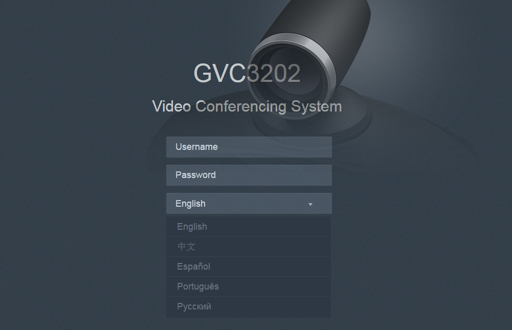
6. Click “Login”  to access the configurations in web UI.
Saving Changes
When changing any settings on the web UI, always submit them by pressing the “Save” button on the bottom of the page, and then clicking the “Apply” button on the top of the page to apply the configuration changes. For those options with icon
![]() next to it in the web page, users must reboot the GVC3200/GVC3202 for the changes to take effect.
next to it in the web page, users must reboot the GVC3200/GVC3202 for the changes to take effect.
Definitions
This section describes the options in the GVC3200/GVC3202 Web GUI. As mentioned in the previous section, you can log in as an administrator or a normal user.
- Call
Users could initiate conference and control conference from Web GUI.
- Contacts
Manage contacts and LDAP client configuration, schedule conference and manage call history.
- Device Control
Device Control and Audio Control.
- Settings
Account, Network Settings, Peripheral, Call Features, General Settings and Security Settings.
- Maintenance
Upgrade, Recording, Time & Language, Troubleshooting and Reboot.
- Status
Account Status, Peripheral Status, Network Status, System Info and Remote Control status.
The following table shows the web pages accessible by end user and administrator.
Table 2: GVC3200/GVC3202 Web Access
User Type | Username | Default Password | Accessible Web Pages |
End User | user | 123 |
|
Administrator | admin | admin | All pages |
Toolbar
The web UI tool bar is on the upper right corner of the web UI page.

- DND
Turn on/off DND mode. Once enabled, the DND text will turn into red in web UI. The LCD for GVC3200/GVC3202 display will shows DND indication on the top of the screen and all incoming calls will be rejected.
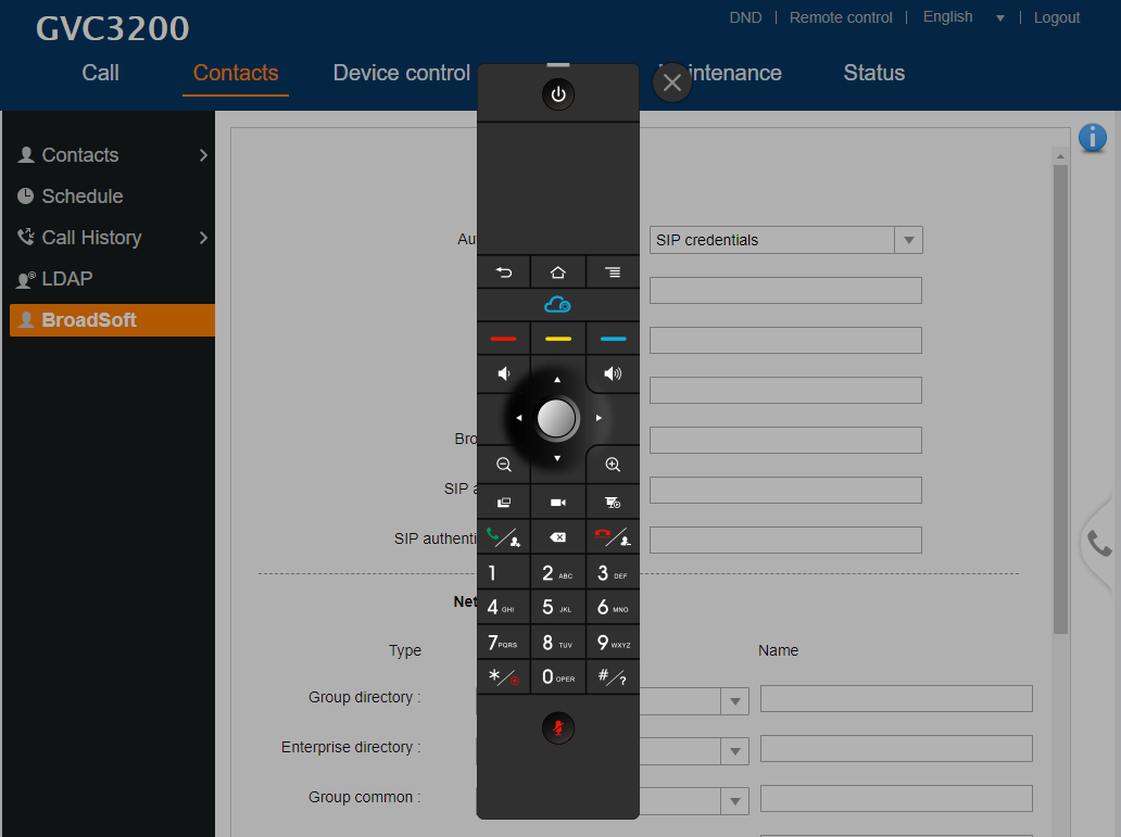
- Remote Control
Click to bring up virtual remote control panel.
- English
Select the display language for the web UI.
- Logout
Log out from the web UI.
Settings
The Settings page lists Account, Network Settings, Peripheral, Call Features, General Settings and Security Settings.
The GVC3200/GVC3202 supports up to 3 accounts:
- One SIP account that the user can register to any SIP platform
- One H.323 account that the user can register to any H.323 platform.
- IPVideoTalk account that is supported by Grandstream’s IPVideoTalk service.
- BlueJeans account.
The following table shows all the settings that SIP and H.323 accounts has. Please note the IPVideoTalk account and BlueJeans account have a subset of the settings that the SIP account has.
Settings/SIP/General
Parameters | Descriptions |
Account Active | This field indicates whether the account is active. If disabled, the device will not send registration information to SIP server. The default setting is enabled. |
Account Name | It is used to configure the name associated with each account to be displayed on the upper left corner of LCD. |
SIP Server | It is used to configure the URL or IP address, and port of the SIP server. This should be provided by VoIP service providers (ITSP). |
Secondary SIP Server | It is used to configure the URL or IP address, and port of the secondary SIP server. When the connection request sent to SIP server fails, the device will try to use the secondary SIP server. |
Tertiary SIP Server | It is used to configure the URL or IP address, and port of the tertiary SIP server. When the connection request sent to SIP server and secondary SIP server fails, the device will try to use the tertiary SIP server. |
SIP User ID | It is used to configure the user account information, provided by your VoIP service provider (ITSP). It’s usually in the form of digits similar to phone number or actually a phone number. |
SIP Authentication ID | It is used to configure the SIP service subscriber’s Authenticate ID used for authentication. It can be identical to or different from the SIP User ID. |
SIP Authentication ID | It is used to configure the SIP service subscriber’s Authenticate ID used for authentication. It can be identical to or different from the SIP User ID. |
SIP Authentication Password | It is used to configure the account password required for the device to authenticate with the ITSP (SIP) server before the account can be registered. After saving, it will appear as hidden for security purpose. |
Voice Mail Access Number | This parameter allows you to access voice messages by entering voice mail or dialing access number. On the device, the users can select LCD menu🡪Applications🡪Voice Mail and click on the account to dial out to voicemail portal. |
Display Name | It is used to configure the SIP server subscriber’s name (optional) that will be used for Caller ID display. The configured content will be included in the From, Contact and P-Preferred-Identity headers of SIP INVITE message. |
Tel URI | If the device has an assigned PSTN telephone number, this field should be set to “User=Phone”. Then a “User=Phone” parameter will be attached to the Request-Line and “TO” header in the SIP request to indicate the E.164 number. If set to “Enable”, “Tel:” will be used instead of “SIP:” in the SIP request. The default setting is “Disable”. |
Settings/SIP/Network
Parameters | Descriptions |
Outbound Proxy | It is used to configure the IP address or the Domain name of the Primary Outbound Proxy, Media Gateway, or Session Border Controller. It’s used by the device for Firewall or NAT penetration in different network environments. If a symmetric NAT is detected, STUN will not work and ONLY an Outbound Proxy can provide a solution. |
Secondary Outbound Proxy | It is used to configure the IP address or the Domain name of the Secondary Outbound Proxy, Media Gateway, or Session Border Controller. The device will try to connect the Secondary outbound proxy only if the primary outbound proxy fails. |
DNS Mode | It is used to set which DNS service will be used to look up IP address for SIP server’s hostname. It can be selected from the dropdown list:
If the device needs DNS SRV resource, in which case the DNS server responds with more than one result, it should be set to “SRV” or “NATPTR/SRV”. The default setting is “A Record”. |
NAT Traversal | It is used to configure the NAT traversal mechanism used on the device. It can be selected from the dropdown list:
If the outbound proxy is configured and used, it can be set to “NAT NO”. If set to “STUN” and STUN server is configured, the device will periodically send STUN message to the SUTN server to get the public IP address of its NAT environment and keep the NAT port open. STUN will not work if the NAT is symmetric type. If set to “Keep-alive”, the device will send the STUN packets to maintain the connection that is first established during registration of the device. The “Keep-alive” packets will fool the NAT device into keeping the connection open and this allows the host server to send SIP requests directly to the registered device. If the device needs to use OpenVPN to connect to host server, please set it to “VPN”. If the firewall and the SIP device behind the firewall are both able to use UPnP, it can be set to “UPnP”. Both parties will negotiate the port used to allow SIP packets to go through. If it is set to “TURN”, the protocol is designed to be used as part of the ICE (Interactive Connectivity Establishment) approach to NAT Traversal. The default setting is “Keep-alive”. |
Proxy-Require | It is used to add the Proxy-Required header in the SIP message. It is used to indicate proxy-sensitive features that must be supported by the proxy. Do not configure this parameter unless this feature is supported on the SIP server. |
Settings/SIP/SIP
Parameters | Descriptions |
SIP Registration | It is used to set if allowing the device to send SIP Register messages to the proxy/server. The default setting is “Yes”. |
Unregister Before New Registration | If it is set to “All”, the SIP user’s registration information will be cleaned when the device starts pre-registration after rebooting. The SIP Contact header will contain “*” to notify the server to unbind the connection. If set to “Instance”, the device only cleans the current SIP user’s info. The default setting is “Instance”. |
Register Expiration (Min.) | It is used to configure the time period (in minutes) in which the device refreshes its registration with the specified registrar. The default setting is 60. The maximum value is 64800 (about 45 days) and the minimum value is 1 minute. |
Wait Time Retry Registration (s) | It is used to configure the time period (in seconds) in which the device will retry the registration process in the event that is failed. The default setting is 20. The maximum value is 3600 (1 hour). |
Local SIP Port | It is used to configure the local SIP port used to listen and transmit. The default setting is 5060. The valid range is from 5 to 65535. |
SUBSCRIBE for MWI | It is used to set if the device will subscribe voice message service. If it is set to “Yes”, the device will periodically send SIP SUBSCRIBE message for Message Waiting Indication service. GVC3200/GVC3202 supports both synchronized and non-synchronized MWI. The default setting is “No”. |
Enable Session Timer | It is used to set if the device will use the session timer. If it is set to “Yes”, it will be added in the SIP INVITE message to notify the server. The default setting is “Yes”. |
Session Expiration (s) | It is used to configure the device’s SIP session timer. It enables SIP sessions to be periodically “refreshed” via a SIP request (UPDATE, or re-INVITE). If there is no refresh via an UPDATE or re-INVITE message, the session will be terminated once the session interval expires. Session Expiration is the time (in seconds) where the session is considered timed out, provided no successful session refresh transaction occurs beforehand. The default setting is 180 with a valid range from 90 to 64800. |
Min-SE (s) | It is used to configure the minimum session expiration timer (in seconds) if the device acts as a timer refresher. The default setting is 90. The valid range is from 90 to 64800. |
UAC Specify Refresher | It is used to set the party which will refresh the active session if the device makes outbound calls. If it is set to “UAC” and the remote party does not support Refresher feature, the device will refresh the active session. If it is set to “UAS”, the remote party will refresh it. If it is set to “Omit”, the header will be omitted so that it can be selected by the negotiation mechanism. The default setting is “Omit”. |
UAS Specify Refresher | It is used to set the party which will refresh the active session if the device receives inbound calls. If it is set to “UAC”, the remote party will refresh the active session. If it is set to “UAS” and the remote party does not support refresh feature, the device will refresh it. The default setting is “UAC”. |
Force INVITE | It is used to set the SIP message type to refresh the session. If it is set to “Yes”, the Session Timer will be refreshed by using the SIP INVITE message. Otherwise, the device will use the SIP UPDATE or SIP OPTION message. The default setting is “No”. |
Caller Request Timer | This is used to set the caller party to act as refresher. If set to “Yes” and both parties support session timers, the device will enable the session timer feature when it makes outbound calls. The SIP INVITE will include the content “refresher=uac”. The default setting is “No”. |
Callee Request Timer | This is used to set the callee party to act as refresher. If set to “Yes” and both parties support session timers, the device will enable the session timer feature when it receives inbound calls. The SIP 200 OK will include the content “refresher=uas”. The default setting is “No”. |
Force Timer | It is used to activate the session timer feature on the device. If it is set to “Yes”, the device will use the session timer even if the remote party does not support this feature. If it is set to “No”, the device will enable the session timer only when the remote party supports this feature. To turn off the session timer, select “No”. The default setting is “No”. |
Enable 100rel | It is used to activate the PRACK (Provisional Acknowledgment) method. This option is very important to support PSTN internetworking. PRACK improves the network reliability by adding an acknowledgement system to the provisional Responses (1xx). If set to “Yes”, the device will respond to the 1xx response from the remote party. The default setting is “No”. |
Caller ID Display | It is used to set the header tag from the SIP INVITE message for the Caller ID display. If it is set to Auto, the device will use one of the available headers in the priority hierarchy of P-Asserted Identify Header, Remote-Party-ID Header and From Header. If it is set to “From Header”, it will use the From Header information for the Caller ID. If it is set to “Disabled”, all the incoming calls Caller ID will be displayed with “Unavailable”. The default setting is “Auto”. |
Use Privacy Header | Controls whether the Privacy header will present in the SIP INVITE message or not, whether the header contains the caller info. When set to “default”, the Privacy Header will show in INVITE only when “Huawei IMS” special feature is on. If set to “Yes”, the Privacy Header will always show in INVITE. If set to “No”, the Privacy Header will not show in INVITE. The default setting is “Default”. |
Use P-Preferred-Identity Header | It is used to set if the P-Preferred-Identity Header will be presented in the SIP INVITE message. If set to “default”, the P-Preferred-Identity Header will be omitted in SIP INVITE message when “Huawei IMS” special feature is active. If set to “Yes”, the P-Preferred-Identity Header will always be presented. If set to “No”, it will be omitted. The default setting is “Default”. |
SIP Transport | It is used to set the protocol used to transport the SIP message. It can be selected from TCP/UDP/TLS. The default setting is “UDP”. |
SIP URI Scheme When Using TLS | It is used to set SIP header – “SIP” or “SIPs”, which will be used if TLS is selected for SIP Transport. The default setting is “SIP”. |
Use Actual Ephemeral Port in Contact with TCP/TLS | It is used to set the port information in the Via header and Contact header of SIP message when the device uses TCP or TLS. If set to “No”, these port numbers will use the permanent listening port on the device. Otherwise, they will use the ephemeral port for the particular connection. The default setting is “No”. |
Symmetric RTP | It is used to enable the symmetric RTP mechanism. If set to “Yes”, the device will use the same socket/port for sending and receiving the RTP messages. Default is “No”. |
It is used to configure whether to filter received RTP packets. The options are “Disable”, “IP Only” and “IP and Port”. The default setting is “Disable”. This setting can be used with “Symmetric RTP”. Please see below:
The device sends RTP packets to the IP:Port included in SDP and accepts RTP packets from any address.
The device sends RTP packets to the IP:Port where the RTP packets come from and accepts RTP packets from any address.
The device sends RTP packets to the IP:Port included in SDP and only accepts RTP packets from the IP in the SDP.
The device sends RTP packets to the IP:Port where the RTP packets come from and only accepts RTP packets from the IP in the SDP.
The device only sends RTP packets to the IP:Port included in SDP and only accepts RTP packets from the IP:Port in the SDP. | |
Support SIP Instance ID | It is used to set if the device will send SIP Instance ID. The SIP instance ID is used to uniquely identify the device. If set to “Yes”, the SIP Register message Contact header will include +SIP.instance tag. The default setting is “Yes”. |
Validate Incoming SIP Messages | It is used to set if the device will check the incoming SIP messages caller ID and Cseq headers. If the message does not include the headers, it will be rejected. The default setting is “No”. |
Check SIP User ID for Incoming INVITE | It is used to set if the device will check the SIP User ID in the Request URI of the SIP INVITE message from the remote party. If it doesn’t match the SIP User ID configured on the device, the call will be rejected. If set to “Yes”, this feature will be active. The default setting is “No”. |
Authenticate Incoming INVITE | It is used to set if the device will authenticate the SIP INVITE message from the remote party. If set to “Yes”, the device will challenge the incoming INVITE for authentication with SIP 401 Unauthorized response. The default setting is “No”. |
SIP Realm Used for Challenge INVITE & NOTIFY | This is used to verify incoming INVITE and NOTIFY (including check-sync, re-sync and reboot). It’s only effective when SIP authentication is enabled. |
Only Accept SIP Requests from Known Servers | It is used to set if the device will answer the SIP request from saved servers. If set to “Yes”, only the SIP requests from saved servers will be accepted and the SIP requests from the unregistered server will be rejected. The default setting is “No”. |
SIP T1 Timeout | It is used to define an estimate of the round-trip time of transactions between a client and server. If no response is received in T1, the figure will increase to 2*T1 and then 4*T1. The request re-transmit retries would continue until a maximum amount of time define by T2. The default setting is 0.5 second. |
SIP T2 Timeout | It is used to define the maximum retransmit time of any SIP request messages (excluding the SIP INVITE message). The re-transmitting and doubling of T1 continues until it reaches the T2 value. The default setting is 4 second. |
Remove OBP from Route | It is used to set if the device will remove outbound proxy URI from the Route header. This is used for the SIP Extension to notify the SIP server that the device is behind a NAT/Firewall. If it is set to “Yes”, it will remove the Route header from SIP requests. The default setting is “No”. |
Check Domain Certificates | It is used to set if the device will check the domain certificates if TLS/TCP is used for SIP Transport. |
When the SIP transport protocol is “TLS” and this option is enabled, the certificates in device system and the trusted CA certificates uploaded by the user will be validated. |
Settings/SIP/Codec
Parameters | Descriptions |
DTMF | It is used to set the parameter to specify the mechanism to transmit DTMF (Dual Tone Multi-Frequency) signals. There are 3 supported modes:
The default setting is “RFC2833”. |
DTMF Payload Type | It is used to configure the RTP payload type that indicates the transmitted packet contains DTMF digits. The valid range is from 96 to 127. The default setting is “101”. |
Preferred Vocoder | It lists the available and enabled audio codecs for this account. Users can enable the specific audio codecs by moving them to the Selected box and set them with a priority order from top to bottom. This configuration will be included with the same preference order in the SIP SDP message. The codec option includes “PCMU”, “PCMA”, “Opus”, “G.722”, “G.722.1”, “G.722.1c”. |
Codec Negotiation Priority | It is used to configure the codec negotiation sequence when the GVC3200/GVC3202 is acted as a callee. If set to “Caller”, the device will negotiate codec by SDP codec sequence from the received SIP INVITE message. If set to “Callee”, the device will negotiate codec according to the codec priority configuration on the device itself. The default setting is “Callee”. |
Silence Suppression | It is used to set the silence suppression/VAD feature. If it is set to “Yes”, when silence is detected, a small quantity of VAD packets (instead of audio packets) will be sent during the period of no talking. If set to “No”, this feature is disabled. The default setting is “No”. |
Voice Frames Per TX | It should be noted that the “ptime” value for the SDP will change with different configurations here. This value is related to the codec used and the actual frames transmitted in payload during the call. e.g.: if set to 2 and the first codec is G.729 or G.711, the “ptime” value is 20ms for the SDP. If the TX exceeds the maximum allowable value, the device will use and save the maximum allowed value according to what the first codec is. For end users, it is recommended to use the default setting, as incorrect settings may influence the audio quality. The default setting is “2”. |
G.722.1 Rate | It is used to select encoding rate for G.722.1 codec. It supports 24kbps or 32kbps. The default setting is “24kbps encoding rate”. |
G.722.1 Payload Type | It is used to configure payload type for G.722.1 codec. The valid range is 100-126. The default setting is “104”. |
Opus Payload Type | It is used to configure payload type for Opus codec. The valid range is 96-126. The default setting is “123”. |
Use First Matching Vocoder in 200OK SDP | If set to “Yes”, the device will use the first matching vocoder in the sent 200OK SDP as the codec. The default setting is “No”. |
Enable RFC5168 Support | If set to “Yes”, the RFC5168 mechanism will be enabled for video call. RFC5168 allows SIP party to request the sender to refresh its video frame in H.264, or refresh the full picture in VP8. The default setting is “Yes”. |
Enable Video FEC | If enabled, the video sender will temporarily allocate part of the bandwidth to one data channel to send FEC data to system, thus to improve the video quality the receiver gets. Enabling this function will take up part of bandwidth and reduce call rate. The default setting is “Yes”. |
Video FEC Mode | If set to 0, FEC is not sent by separate port. If set 1, FEC is sent by separate port. Default setting is 0. |
FEC Payload Type | It is used to configure FEC payload type. The range is 96-127. The default setting is 120. |
Enable FECC | If set to “Yes”, You can control the camera of the opposite side for video call, but the opposite site must support FECC, and allow remote control on its local camera. The default setting is “Yes”. |
FECC H.224 Payload Type | It is used to configure FECC H.224 payload type. The valid range is from 96 to 127. The default value is 125. |
H.264 Payload Type | It is used to configure the H.264 codec message payload type format. The default setting is 99. The valid range is from 96 to 127. |
Packetization-mode | The packetization mode can be set to 0, 1 or Auto. When it’s set to 0 or 1, the INVITE will include packetization mode value as 0 or 1. If it’s set to Auto, the INVITE will include both 0 and 1, and the packetization mode value is a result of negotiation between the endpoint and the server. Default setting is 1. |
H.264 Image Size | It is used to set the H.264 image size. It can be selected from the dropdown list.
The default setting is 1080P. |
H.264 Profile Type | It is used to set the H.264 profile type. It can be selected from the dropdown list.
The default setting is “BP&MP&HP”. Lower profile is easier to decode while higher profile provides higher compression ratio. For device with low CPU, select “Baseline Profile”. Also, “Baseline Profile” is likely to be used in a video conference that has high demanding for the video quality. |
Video Bit Rate | It is used to configure the bit rate of the video device. The default setting is 2048kpbs. It is recommended to increase bit rate if bandwidth allows. If the bandwidth is not enough, the video quality will be reduced.
|
SDP Bandwidth Attribute | Select the SDP bandwidth attribute from “Standard”, “Media Level” or “None”. The default setting is “Media Level”.
Note: Please do not change the format as it may cause decode failure if the user is unclear about what format the server supports. |
Video Frame Rate | Configures the frame rate for SIP video call. The default is 30 fps. Increase frame rate will take up bandwidth; the video quality will be reduced if not allocated enough bandwidth. |
Video Jitter Buffer Maximum (ms) | Configures the video buffer size according to the network environment. The valid range is 0-1000, the default setting is 50. |
Disable Presentation | If set to “Yes”, the device will disable presentation and will not receive presentation during video call. The default setting is “No”. |
Initial INVITE with media info | If it is enabled, the initial INVITE packet sent from GVC to server will carry BFCP media information. If not, the related media info will be included in re-INVITE packet and the BFCP negotiation with some specific servers might be failed. |
Presentation H.264 Image Size | It is used to select the H.264 image size from “720P” or “1080P”. The default setting is “1080P”. |
Presentation H.264 Profile Type | Select the H.264 profile type from “Baseline Profile”, “Main Profile”, “High Profile” or “BP&MP&HP”. The default setting is “BP&MP&HP”. Lower profile type is easier to decode, while higher level has higher compression ratio. For device with low CPU, select “Baseline Profile”. Also, “Baseline Profile” is likely to be used in a video conference that has high demand for the video quality. |
Presentation Video Bit Rate | Configures the bit rate of the video. The video bit rate can be adjusted based on the network environment. Increasing the video bit rate may improve video quality if the bandwidth is permitted. If the bandwidth is not permitted, the video quality will decrease due to packet loss. The default setting depends on presentation H.264 image size.
|
Presentation Video Frame Rate | Configures the video frame rate for presentation. The options are 5fps, 10fps and 15fps. The default setting is 15fps. |
BFCP Transport Protocol | Defines the transport protocol used for BFCP. Users can choose from Auto/UDP/TCP. The default setting is “UDP”. If “Auto” is configured, the device will automatically switch between “UDP” and “TCP”. |
SRTP Mode | It is used to set if the device will enable the SRTP (Secured RTP) mode. It can be selected from dropdown list:
SRTP uses encryption and authentication to minimize the risk of denial of service. (DoS). If the server allows to use both RTP and SRTP, it should be configured as “Enabled but not forced”. The default setting is “Enabled But Not Force”. |
SRTP Key Length | It is to configure all the AES (Advanced Encryption Standard) key size within SRTP. It can be selected from dropdown list:
If it is set to “AES 128&256 bit”, the device will provide both AES 128 and 256 cipher suite for SRTP. If set to “AES 128 bit”, it only provides 128-bit cipher suite; if set to “AES 256 bit”, it only provides 256-bit cipher suite. The default setting is “AES 128&256 bit”. |
Settings/SIP/Call
Parameters | Descriptions |
Remote Video Request | It is used to set the preference to handle video request from the remote party during an audio call. It can be selected from the dropdown list.
The default setting is “prompt”. |
Common Layout Mode | Adjusts the initial layout for video display for meetings. There are 4 available modes for users: Remote mode, Average mode and PIP mode. |
DialPlan Prefix | It is used to configure the prefix to be added to each dialed number. All numbers use this account will automatically add the prefix. e.g.: The prefix is 5, the phone number is 337, and then the dial number is 5337. |
DialPlan | Dial Plan Rules: 1. Accepted Digits: 1,2,3,4,5,6,7,8,9,0 , *, #
Set to {x+} allows dial out with all digits. Example:
|
Refer-To Use Target Contact | It is used to set if the device will use the target’s Contact header tag to the Refer-To header in the SIP REFER message during an attended transfer. Default setting is “No”. |
Auto-Answer | It is set to allow answering an incoming call. If it is set to “Yes”, the device will automatically enable the speaker phone to answer all the incoming calls after a short reminding beep. If set to “Enable Intercom/Paging”, it will automatically answer the incoming calls whose SIP INVITE includes auto-answer tag in the info header. The default setting is “No”. |
Send Anonymous | It is used to set if the device will make an anonymous outgoing call. If it is set to “Yes”, the “From” header in the SIP INVITE messages will be set to anonymous, essentially blocking the Caller ID to be displayed. The default setting is “No”. |
Reject Anonymous Call | If it is set to “Yes”, the device will reject the calls whose SIP INVITE message includes Anonymous information in the From header. The default setting is “No”. |
Call Log | It is used to categorize the call logs saved for this account. If it is set to “Log All”, all the call logs of this account will be saved. If set to Log Incoming/Outgoing Calls (Missed Calls Not Record), the whole call history will be saved other than missed call. If it set to Disable Call All, none of the call history will be saved. The default setting is “Log All”. |
Special Feature | It is to configure device’s setting to meet different vendors server requirements. Users can choose from Standard, Broadsoft, CBCOM, RNK, China Mobile, ZTE IMS, Mobotix, ZTE NGN, or Huawei IMS depending on the server type. The default setting is “Standard”. |
Feature Key Synchronization | It is used for the Broadsoft standard call feature synchronization. If it is enabled, the device will send SIP SUBSCRIBE message to the server and receive SIP NOTIFY message from the server to synchronize the DND, Call Forwarding and Call Center features. The default setting is “Disable”. |
Enable Call Features | If set to “Yes”, call features (including call forwarding, DND and etc.) will be supported locally instead of using the feature code supported on SIP server/proxy. For example, if *72+number is dialed, the incoming calls will be forward to this number unconditionally. The default setting is “No”. Refer to the chapter Call Features for more details in the GVC3200/GVC3202 User Guide. |
Ring Timeout (s) | It is used to define the expiration timer (in seconds) for the rings with no answer. The default setting is 60. |
Transfer on 3-way conference Hangup | It is to set if the device will end the three-way conference hosted on it if it hangs up. If set to “Yes”, the conference will be transferred from hosted party, thus other parties can continue the conference without interruption. The default setting is unchecked. |
Use # as Dial Key | It is used to set the device whether to use the “#” key as the “Send” key. If set to “Yes”, if the end user taps the “#” key on the remote control, the device will send out the typed digits. If set to “No”, the “#” key is included as part of the dialing string and please make sure the dial plan is properly configured to allow dialing # out. The default setting is “Yes”. |
Conference-URI | It is used to configure the network based conference URI (Broadsoft Standard). If it is configured, end user needs to select MORE on the bottom menu in call interface and click on “N-way Conf” during the conference to transfer the host to the remote media server. |
Upload Local MOH Audio File | It is used to load the MOH (Music on Hold) file to the device. Click on “Browse” button to upload the music file from local PC. The MOH audio file has to be in .wav or .mp3 format. Note: Please be patient while the audio file is being uploaded. It could take more than 3 minutes to finish the uploading especially the file size is large. The button will show as “Processing” during the uploading. Once done, it will show as “Browse” again. Click on “Save” on the bottom of the web page and “Apply” on the top of the web page to save the change. |
Enable Local MOH | If set to “Yes”, the local MOH will be enabled. Users need to upload local MOH audio file. Once enabled, users could play the file when holding the call. Default setting is No. |
Account Ring Tone | It is used to configure the ringtone for the account. Users can set ringtones from the dropdown list. User can also import customized ringtone from LCD Setting menu. The customized ringtone file name will also be showed up in the dropdown list that allows user to select. |
Call Forwarding Mode | It is used to set the Call Forwarding feature for this account. - None: Setting the feature to NONE will disable Call Forward. - Unconditional: If set to UNCONDITIONAL, it will forward all calls to a particular number. - Time based: With TIME BASED forward, set a time range for the calls to be forwarded:
- Others: When set to OTHERS, the call forwarding rules can be customized based on following options:
|
Match Incoming Caller ID | It is used to specify the rules for the incoming calls. If the incoming caller ID or Alert Info matches the number, pattern or Alert Info text rules, the device will play the selected distinctive ringtone. The rule policy:
Samples:
Alert Info text: users could configure the matching rule as certain text (e.g., priority) and select the custom ring tone mapped to it. The custom ring tone will be used if the device receives SIP INVITE with Alert-Info header in the following format: Alert-Info: <http://127.0.0.1>; info=priority |
Distinctive Ring Tone | It is used to select the distinctive ring tone if the incoming caller ID matched the specified Matching Incoming Caller ID rule. If so, the device will play the selected ringtone. |
Settings/IPVideoTalk/General
Parameters | Descriptions |
Account Active | It is used to indicate whether if the built-in IPVideoTalk account is active. The default setting is “Enabled”. |
Current Plans | This field indicates the current plan of IPVideoTalk Cloud Service. |
Display Name | It is used to define the displayed name shown on the callee side once the GVC3200/3202 makes an IPVideoTalk call. |
SIP Transport | It is used to set the protocol used to transport the SIP messages. The default setting is “TLS”. |
Settings/IPVideoTalk/Call
Parameters | Descriptions |
Auto Answer When Idle | If the GVC320x is not in a call/in a meeting/not busy, the GVC320x will auto answer the incoming call even during the sleep mode. |
Common Layout Mode | Adjusts the initial layout for video display for meetings. There are 4 available modes for users: Remote mode, Average mode and PIP mode. |
Settings/BlueJeans/General
Parameters | Descriptions |
Account Active | It is used to indicate whether if the BlueJeans account is active. The default setting is “Yes”. |
Display Name | It is used to define the displayed name shown on the callee side once the GVC3200/3202 makes a BlueJeans call. |
Settings/BlueJeans/Codec
BlueJeans account Codec section is the same as on SIP account. Please refer to the Settings/SIP/Codec section for more details.
Settings/BlueJeans/Call
BlueJeans account Call section is the same as on SIP account. Please refer to the Settings/SIP/Call section for more details.
Settings/H.323/General
Parameters | Descriptions |
Account Active | This field indicates whether the H.323 account is active. The default setting is “No”. |
Enable GK | This defines whether to enable GK. If enabled, the device will register to GK automatically. The default setting is “No”. |
Enable H.460 | It is used to define whether to enable H.460.18/19 to support H.323 account, in order to make the IP calls through public Internet without intermediate nodes. To use this feature, set “Use NAT IP” to the public IP for GVC3200/3202 under GVC3200/GVC3202 web UI🡪Settings🡪General Settings. |
GK Discover Mode | This configures GK discover mode to be “Auto” or “Manual”.
The default setting is “Auto”. |
Site Number | It used to configure H.323 conference ID of the GVC3200/3202. The GVC3200/3202 can be reached by calling the site number. The site number is numeral only. |
GK Authentication Username | Enter the username for GK authentication. |
GK Authentication Password | Enter the password for GK authentication. |
Register Expiration (Min.) | This specifies the frequency (in minutes) in which the device refreshes its registration with the specified registrar. The default value is 60 minutes (1 hour). The maximum value is 1,440 minutes (1 day). The minimum value is 1 minute. |
H.323 Local Port | This defines the local H.323 port used to listen. Default value is 1720. |
Symmetric RTP | It is used to enable the symmetric RTP mechanism. If set to “Yes”, the GVC3200/3202 will use the same socket/port for sending and receiving the RTP messages. The default setting is “No”. |
Settings/H.323/Codec
Parameters | Descriptions |
DTMF | This parameter specifies the mechanism to transmit DTMF digits. There are 3 supported mode:
|
Preferred Vocoder | PCMA, PCMU, G.722 and G.722.1 are supported on the device for the H.323 account. Users can select the vocoder from the “Available” list to “Selected” list, and configure the vocoder priority by adjusting the order in the “Selected” list. The “Selected” vocoders will be included in the SDP message with the same order. |
H.264 payload type | It is used to configure the H.264 codec message payload type format. The default setting is 99. The valid range is from 96 to 127. |
H.264 image size | It is used to set the H.264 image size. It can be selected from the dropdown list.
The default setting is 1080P. |
Video bit rate | It is used to configure the bit rate of the video device. The default setting is 2048kpbs. It is recommended to increase bit rate if bandwidth allows. If the bandwidth is not enough, the video quality will be reduced.
H.264 Image Size = 4SIF/4CIF/VGA, the Video Bit Rate can be set to a value from 384 to 1024 Kbps. |
Video frame rate | It is used to configure the video frame rate. The supported video frame rates are 5 fps, 15fps, 25 fps, 30 fps and VFR. The default setting is “30 fps”. |
Settings/H.323/Call
Parameters | Descriptions |
Auto-Answer | If set to “Yes”, the device will automatically turn on the speaker to answer incoming calls after a short reminder beep. The default setting is “No”. |
Enable H225 Keep-alive | If enabled, the device will only send H255 keep-alive as callee and the interval is 19 seconds. The default setting is “No”. |
Enable H245 Keep-alive | If enabled, the device will send H245 keep-alive packet as caller or callee, and the interval is 19 seconds. The default setting is “No”. |
Enable RTDR | If enabled, the device will send RTDP (roundTripDelayRequest) packet as H245 keep-alive packet every 10 seconds. The timeout interval is 30 seconds and will hang up the call once timed out. The default setting is “No”. Note: If enabled, it may cause incompatibility issue with certain devices. |
Common Layout Mode | Adjusts the initial layout for video display for meetings. There are 4 available modes for users: Remote mode, Average mode and PIP mode |
Settings/Network Settings
Network Settings lists Basic Settings, 802.1X, QoS, Proxy and Advanced Settings.
Parameters | Descriptions |
Basic Settings | |
Preferred Internet protocol | Allows user to select the preferred Internet Protocol whether IPv4 or IPv6. |
Address Type | Allows users to configure the appropriate network settings on the device. Users could select “DHCP”, “Static IP” or “PPPoE”. By default, it is set to “DHCP”.
|
DHCP Option 132 defines VLAN ID and DHCP Option 133 defines priority tag ID. GVC320x supports DHCP VLAN override via DHCP Option 132 and DHCP Option 133, or encapsulated DHCP Option 132 and DHCP Option 133 in DHCP Option 43.
• When set to “Encapsulated in DHCP Option 43”, the GVC320x will get VLAN ID and VLAN priority value from the DHCP Option 43 which has DHCP Option 132 and DHCP Option 133 encapsulated. In this case, please make sure the option “Allow DHCP Option 43 and Option 66 to Override Server” is enabled under GVC320x webUI🡪Maintenance🡪Upgrade. | |
Host name (Option 12) | It is used to configure the name of the client in the DHCP request. It is optional but may be required by some Internet Service Providers. |
Vendor Class ID (Option 60) | It is used to configure the vendor class ID header in the DHCP request. The default setting is “Grandstream GVC3200” for GVC3200 and “Grandstream GVC3202” for GVC3202. |
DHCP Option 120 Override SIP Server | Enables DHCP Option 120 from local server to override the SIP Server on the device when DHCP is used. The default setting is “Yes”. |
IP Address | It is used to configure the device’s static IP address if the static IP is used. |
Subnet Mask | It is used to configure the network’s subnet mask if the static IP is used. |
Default Router | It is used to configure the network’s gateway address if the static IP is used. |
DNS Server 1 | It is used to configure the primary DNS IP address if the static IP is used. |
DNS Server 2 | It is used to configure the secondary DNS IP address if the static IP is used. |
PPPoE Account | It is used to configure the PPPoE account ID if the PPPoE is used. |
PPPoE Password | It is used to configure the PPPoE password if the PPPoE is used. |
802.1x Mode | |
802.1x Mode | It is used to enable and select the 802.1x mode for the device. The supported 802.1x modes are:
The default setting is “Close”. |
802.1x Identity | It is used to fill in the identity information for the selected 802.1x mode. This setting will be displayed only if 802.1x mode is enabled. |
802.1x Secret | It is used to enter the secret for the 802.1x mode. This setting will be displayed only if the 802.1x mode is enabled. |
Private Key | It is used to enter the private key password for the 802.1x mode. This setting will be displayed only if the 802.1x mode is enabled. |
CA Certificate | It is used to upload the CA Certificate file to the device. This setting will be displayed only if the 802.1x mode is enabled. |
Client Certificate | It is used to load the Client Certificate file to the device. This setting will be displayed only if the 802.1x TLS mode is enabled. |
QoS | |
Enable LLDP | It is used to enable the LLDP (Link Layer Discovery Protocol) feature on the device. If it is set to “Yes”, the device will broadcast LLDP PDU to advertise its identity and capabilities and receive same from a physical adjacent layer 2 peer. The default setting is “Yes”. |
Layer 3 QoS for SIP | It is used to define the Layer 3 packet’s QoS parameter for SIP messages in decimal pattern. This value is used for IP Precedence, Diff-Serv or MPLS. The default setting is 48 which is equivalent to the DSCP name constant CS6. |
Layer 3 QoS for Audio | It is used to define the Layer 3 packet’s QoS parameter for RTP messages in decimal pattern. This value is used for IP Precedence, Diff-Serv or MPLS. The default setting is 48 which is equivalent to the DSCP name constant CS6. |
Layer 3 QoS for Video | It is used to define the Layer 3 packet’s QoS parameters for H.264 messages in decimal pattern. This value is used for IP Precedence, Diff-Serv or MPLS. The default setting is 48 which is equivalent to the DSCP name constant CS6. |
Layer 2 QoS 802.1q/VLAN Tag | It is used to define the VLAN Identifier of the Layer 2 frames. The default value 0 which means the frame does not belong to any VLAN. Note: Please do not change the setting before understanding the VLAN’s settings. Otherwise the device can’t get the correct IP address. |
Layer 2 QoS 802.1p Priority | It is used to define the Priority Code Point within a Layer 2 frame header. The valid range from 0 to 7. The Default value is 0 which is equivalent to the Routine class for the Class of Service. |
Proxy | |
HTTP/HTTPS Proxy Hostname | It is used to configure the HTTP/HTTPS proxy URI of the network. Some of networks require going through a proxy to access to the Internet. The default setting is keeping this field blank. |
HTTP/HTTPS Proxy Port | It is used to configure the HTTP/HTTPS proxy port number of the network. Some of networks require going through a proxy to access to the Internet. The default setting is keeping this field blank. |
Bypass Proxy For | It is used to define the specific URI that the device can directly access to without HTTP/HTTPS proxy. If it is filled, the device will bypass the proxy to send the packets to the specific URI. The default setting is keeping this filed blank. |
Advanced Settings | |
Alternate DNS Server | It is used to configure the alternate DNS IP address to failover during the default DNS server’s outage. |
Secondary DNS Server | It is used to configure the secondary alternate DNS IP address to failover during both the default DNS server and alternate DNS server’s outage. |
User-Agent | It is used to configure the User-Agent URI to download phonebook and screensaver files. |
It is used to configure the User-Agent field for SIP messages. If not configured, the User-Agent in SIP message is Grandstream GVC3200 1.0.1.27 where GVC3200 is the model name and 1.0.1.27 is the current firmware version. If configured to “test”, the User-Agent field for SIP message will become test GVC3200 1.0.1.27 where GVC3200 is the model name and 1.0.1.27 is the current firmware version. | |
IPv6 | |
IPv6 address | Allows users to choose whether to get automatically the IPv6 address from DHCP server (Auto-configured), or configure a static IPv6 address (Statically configured). Default is Auto-configured. |
Static IPv6 address | It is used to configure a static IPv6 address if Statically configured is used. |
IPv6 prefix length | It is used to set the IPv6 prefix length if Statically configured is used. Default is 64. |
DNS server 1 | It is used to configure the primary DNS IP address if Statically configured is used. |
DNS server 2 | It is used to configure the secondary DNS IP address if Statically configured is used. |
Preferred DNS server | It is used to configure the preferred DNS server. |
Settings/Peripheral
Parameters | Descriptions |
HDMI | |
HDMI 1 out resolution | Configures the output image resolution of HDMI 1. Greater resolution value means higher image definition. Please select the same resolution as the output display device. The device will automatically read the resolution supported by the output display device and compare it with the resolution supported by itself. Only the resolution supported by both will be used. The device will automatically obtain the optimal resolution when it boots up for the first time. |
HDMI 2 out resolution | Configures the output image resolution of HDMI 2. Greater resolution value means higher image definition. Please select the same resolution as the output display device. The device will automatically read the resolution supported by the output display device and compare it with the resolution supported by itself. Only the resolution supported by both will be used. The device will automatically obtain the optimal resolution when it boots up for the first time. |
Screen percent | Configures the output image size on the screen of HDMI 1 output. The value range is 90%-100%. The default setting is 100%. |
Whether to enable presentation automatically when HDMI/VGA is plugged. Default is “No”:
| |
Camera | |
Move speed | Specifies the moving speed and zoom speed for the camera. “1” is slowest and “16” is fastest. The default setting is “8”. |
Initial position | Specifies the initial position of the camera when the device is powered up.
|
Image offset | |
Image shift | Image offset may occur in VGA input. Users can select horizontal offset to adjust the image’s horizontal position or select vertical to adjust the image’s vertical position. |
VGA in | This option is used to adjust the parameters of horizontal or vertical offset in the image shift of VGA input. |
Sampling phase | |
VGA in | A blurring or slight jitter issue may occur in VGA input. Users can set the sampling phase to adjust the color. |
OLED indicator | |
Disable missed call OLED indicator | If set to “Yes”, the OLED will not indicate when there is missed call on the device. The default setting is “No”. |
Disable MWI OLED indicator | If set to “Yes”, the OLED will not indicate when there is an unread voice email. The default setting is “No”. |
Disable new message OLED indicator | If set to “Yes”, the OLED will not indicate when there is new message on the device. The default setting is “No”. |
Disable contacts full OLED indicator | If set to “Yes”, the OLED will not indicate when the contact storage or message storage is full. The default setting is “No”. |
Settings/Call Features
Parameters | Descriptions |
Start Video Automatically | It is used to set if the device will enable the video feature automatically when it makes an outbound call. If set to “Yes”, the video codec attributes will be included in the SIP INVITE message. Or the attributes will not be included. The default setting is “Yes”. |
Always Ring Internal Ringer | If set to “Yes”, the device will always ring internal speaker. The default setting is “No”. |
Disable DialPlan | Defines whether to disable dial plan in dial screen, contacts, incoming call and outgoing calls and MPK. The default setting is “No”. |
Configures the characters for filter when dialing out numbers. Multiple characters are allowed. For example, if set to [()-], when dialing (0571)-8800-8888, the characters ()- will be automatically filters and number 057188008888 will be dialed directly. The default setting is [()-]. | |
Disable Call-Waiting | It is used disable call waiting feature. If it is checked, the device will reject the second incoming call during an active session without user’s knowledge. But this missed call record will be saved to remind users. The default setting is “No”. |
Disable Call-Waiting Tone | If set to “Yes”, call waiting tone will be disabled when there is a new call during active call. The default setting is “No”. |
Disable DND Reminder Ring | It is used to set if the device will play the DND reminder ringtone for the incoming call if the DND feature is enabled. If it set to “Yes”, the device will keep mute instead of playing a ring splash to indicate an incoming call when DND is enabled. The default setting is “No”. |
Disable Direct IP Call | It is used to set if the device allows the end users to make an outbound IP call. If it is set to “Yes”, the device will hide the IP call feature and end users will not be allowed to make an outbound IP call. The default setting is “No”. |
Use Quick IP-call mode | It is used to set if the device will automatically fill in the first three octets to make an outbound IP call regardless of subnet mask. If it is set to “Yes”, users can dial an IP address under the same LAN/VPN segment by entering the last octet in the IP address from its local IP address. The port number used for the target IP address is 5060 by default. Please note the leading 0 in the last octet needs to be omitted. For example, to make direct IP call to aaa.bbb.ccc.XXX, dial XXX on device directly. No SIP server is required to make quick IP call. The default setting is “No”. |
Enable Frame Skipping in Video Decoder | It is used to reduce video distortion. If set to “Yes”, the GVC3200/3202 will skip the P frame in lost video packet to decode I frame in the next video packet. The default setting is “No”. |
Escape ‘#’ as %23 in SIP URI | It is used to set what characters will be included in the SIP INVITE URI if end users input #. If it is set to “Yes”, the device will replace the # by %23. Otherwise, it will include # in the SIP INVITE message. The default setting is “Yes”. |
Allows users to select whether to enable MUTE on incoming call or outgoing call. If enabled, the GVC320x will become automatically muted once the incoming call or outgoing call is established. The default setting is “Disable”. |
Settings/General Settings
Parameters | Descriptions |
Power Management | |
Enter Sleep Mode (Min.) | Specifies the period before the device enters sleep mode if no operation is performed. If set "Never", the device will never enter sleep mode automatically. The default value is "Never". If the device enters sleep mode, press POWER button on the remote control to boot up. When the device is in sleep mode, there is no display on the display device and web UI access is not available for remote access. Users must use the remote control to wake up the device or reboot the device. |
Site Name Settings | |
Background Transparency | Set the display background transparency to be Opaque, 5%, 10%,15% and 20%. The default setting is "Opaque". |
Site Name | Specifies the site name to be imposed on the video of local video. When joining a multipoint conference, this site name is displayed in other participants' video. |
Display Position | It is used to configure the site name’s position to be at Upper Left Corner, Upper Right Corner, Lower Left Corner or Lower Right Corner on the video. The default setting is "Upper Left Corner". |
Display Duration | It is used to configure the duration to display the site name. The options are “Do Not Display”, “1 Minute”, “5 Minutes”, “10 Minutes” or “Always Display”. The default setting is "Always Display”. |
Font Color | It is used to specify the color in which the site name is displayed. Click on the field and color selection will be available for the user to choose. The default color is white. |
Font Size | It is used to specify the font size for the site name display. The user could select from the smallest to the largest. The default value is Medium. |
Bold | It is used to specify whether the site name is displayed in bold. The default value is No. |
Horizontal Offset | Fine-tunes the site name's position left or right on the local video. |
Vertical Offset | Fine-tunes the site name's position up or down on the local video. |
Others | |
Remote control model | This parameter allows users to select the remote control model to be used. |
Fan Speed | It is used to set the fan speed of the device, the default setting "Normal" means slow speed and lower noise while "Full Speed" means fast speed and high noise. |
Local RTP Port | This parameter defines the local RTP-RTCP port pair used to listen and transmit. It is the base RTP port for channel 0. When configured, for audio, channel 0 will use this port_value for RTP and the port_value+1 for its RTCP; channel 1 will use port_value+6 for RTP and port_value+7 for its RTCP. For video, channel 0 will use port_value+2 for RTP and port_value+3 for its RTCP; channel 1 will use port_value+8 for RTP and port_value+9 for RTCP. The default value is 5004. |
Use Random Port | When set to "Yes", this parameter will force random generation of both the local SIP and RTP ports. This is usually necessary when multiple devices are behind the same full cone NAT. The default setting is "No". Note: This parameter must be set to "No" for Direct IP Calling to work. |
Disable In-call DTMF Display | It will enable/disable the device to omit the DTMF digits displaying from the LCD screen. The default setting is "No". |
Disable Remote Control App Connect | If set to “Yes”, the Remote-Control app can be paired to the GVC3200/GVC3202 via Bluetooth, but it cannot connect to the GVC3200/GVC3202 to perform any operations. The default setting is “No”. |
Remote Control Touchpad Sensitivity | Configure the sensitivity of the remote-control trackpad. Users can select Slow, Normal or Fast. The default setting is Normal. |
Keep-alive Interval (s) | It is used to specify how often the device will send a Binding Request packet to the SIP server in order to keep the "ping hole" on the NAT router to open. The default setting is 20 seconds. The valid range is from 10 to 160. |
STUN/TURN Server | It is used to configure the URI of STUN (Simple Traversal of UDP for NAT) / TURN (Traversal Using Relays around NAT) server. The device will send STUN Binding Request packet to the STUN server to learn the public IP address of its network. Only non-symmetric NAT routers work with STUN. The default setting is "stun.ipvideotalk.com". |
TURN Server Username | It is used to configure the username for TURN server. |
TURN Server Password | It is used to configure the password for TURN server. |
Use NAT IP | It is used to configure the IP address for the Contact header and Connection Information in the SIP/SDP message. It should ONLY be used if it's required by your ITSP. The default setting is keep the box blank. |
Settings/Security Settings
Parameters | Descriptions |
Web/SSH Access | |
Disable SSH | It is used to set if the device will block the SSH port. If it is set to “Yes”, the device will block any SSH access to it. The default setting is “No”. |
Access Method | It is used to set which protocol will be used to access the device’s Web GUI. It can be selected from HTTP and HTTPS. The default setting is HTTP. |
Port | It is used to set which port will be used to access the device’s Web GUI. By default, if HTTP is selected, the port number will be 80; if HTTPS is selected, the port number will be 443. |
Admin Password | It is used to set the administrator password for Web GUI. It is case sensitive with a maximum length of 32 characters. The default password is “admin”. |
User Password | It is used to set the user password for Web GUI. It is case sensitive with a maximum length of 32 characters. The default password is “123”. |
Screen lock | |
Delete screen lock password | Allows the administrator to clear the screen lock password without submitting the old one if it was configured. |
Screen lock password | Allows the administrator to set a password for screen lock. The field supports 6-digit number. |
Confirm screen lock password | It is used to enter the new screen lock password again to confirm. |
SIP | |
SIP TLS Certificate | Defines the SSL certificate used for SIP over TLS to access particular websites. The device supports SIP over TLS encryption, realizing it via the built-in private key and SSL certificate. The SSL certificate the user specifies for TLS encryption should be X.509 format. |
SIP TLS Private Key | Defines the SSL private key used for SIP over TLS. The SSL private key the user specified for TLS encryption should be X.509 format. |
SIP TLS Private Key Password | Defines the SSL private key password used for SIP over TLS. |
Minimum TLS version | Defines the minimum accepted TLS version by the GVC. Options are: 1.0, 1.1 and 1.2. |
Maximum TLS version | Defines the maximum accepted TLS version by the GVC. Options are: 1.0, 1.1 and 1.2. |
Used to upload trusted CA certificates. Users could upload up to 6 trusted CA certificates to be used for application as well as SIP calls when TLS is used. | |
Uploads certificate file from PC using Browse button. The certificate file should be “.pem”, “.crt”, and “.cer” or “.der” format. The Browse button will turn to “Processing” and back to “Browse” once the uploading is finished.
|
Maintenance
Maintenance section lists Upgrade, Recording, Time & Language, Troubleshooting and Reboot.
Maintenance/Upgrade
Parameters | Descriptions |
Complete Upgrade |
For example: if the device can’t fully boot-up but the user still login web UI, please enable this feature to recover the system. |
Upload Firmware File to Update | Manually upload firmware file from PC to the device system directly. |
Firmware Upgrade Mode | It is used to set the upgrading protocol for the device to retrieve firmware file. It can be selected from TFTP, HTTP and HTTPS. The default setting is HTTPS. |
Firmware HTTP/HTTPS Username | It is used to type the user name for the HTTP/HTTPS server authentication for firmware server. |
Firmware HTTP/HTTPS Password | It is used to type the password for the HTTP/HTTPS server authentication for firmware server. |
Firmware Server Path | It is used to define the server path for upgrading the firmware. It can be different from the Config Server Path. Default setting is “fm.grandstream.com/gs”. |
Firmware File Prefix | It is used to set the prefix characters for the firmware files. If it is configured, only the firmware with the matching encrypted prefix will be downloaded and flashed into the device system. It allows the ITSP to lock firmware updates. |
Firmware File Postfix | It is used to set the post characters for the firmware files. If it is configured, only the firmware with the matching encrypted postfix will be downloaded and flashed into the device system. It allows the ITSP to lock firmware updates. |
Use Grandstream GAPS | It’s used to configure the download path and update mode for the configuration file server. If set to “Yes”, the GVC320x will set the download path of the configuration file to fm.grandstream.com/gs by default, and use HTTPS protocol to connect to the server. If set to “No”, users can manually configure the path and update mode to retrieve the configuration file. |
Config Upgrade Mode | When “Use Grandstream GAPS” is set to “No”, users can use this option to set the provisioning protocol for the device to retrieve the config file. It can be selected from TFTP, HTTP and HTTPS. The default setting is HTTPS. |
Config HTTP/HTTPS Username | It is used to type the user name for the HTTP/HTTPS server authentication for config server. |
Config HTTP/HTTPS Password | It is used to type the password for the HTTP/HTTPS server authentication for config server. |
Config Server Path | When “Use Grandstream GAPS” is set to “No”, users can use this field to define the server path for provisioning the configuration file. It can be different from the Firmware Server Path. Default setting is “fm.grandstream.com/gs”. |
Config File Prefix | It is used to set the prefix characters for the configuration files. If it is configured, only the firmware with the matching encrypted prefix will be downloaded and flashed into the device system. |
Config File Postfix | It is used to set the prefix characters for the configuration files. If it is configured, only the firmware with the matching encrypted postfix will be downloaded and flashed into the device system. |
XML Config File Password | The password for encrypting the XML configuration file using OpenSSL. The password is to decrypt the XML configuration file if it is encrypted via OpenSSL. |
Authenticate Conf File | It is used to set if the device authenticates the configuration file before applying it. If it set to “Yes”, the configuration file must include value P1 with device’s administration password. If it is missed or does not match the password, the device will not apply the configuration in the config file. The default setting is “No”. |
Download Device Configuration | It is used to download the device configuration file in text format. The config file includes all the P value parameters for device’s current settings except password for security purpose. |
Upload Device Configuration | It is used to upload the configuration file to the device. |
Always send HTTP Basic Authentication Information | It is used to set if the device includes the credential information in the HTTP/HTTPS request messages to download the cfg.xml file. If it is set to “Yes “, the credential information will always be included in the HTTP/HTTPS messages regardless the server’s challenge. The default setting is “No”. |
GUI customization file URL | This setting defines the server path for the GUI customization file where the GVC320x will download it from. Default value is fm.grandstream.com/gs. |
GUI customization file download mode | Select the GUI customization file download mode: “HTTP”, “HTTPS” or “TFTP”. |
GUI customization file HTTP/HTTPS username | Enter the username to access the HTTP/HTTPS server to download cust file, if required by the server. |
GUI customization file HTTP/HTTPS password | Enter the password to access the HTTP/HTTPS server to download cust file, if required by the server. |
Use Configurations of Config File Server | If selected, the GVC3200/GVC3202 will download the cust file in the same way as retrieving configuration file, i.e., same server and downloading mode, etc. |
Automatic Upgrade | |
Automatic Upgrade | Enables automatic upgrade and provisioning. The default setting is “Check Every Day”. If set to “Check Every Day”, “Check Every Week” or “Check at a Period Time”, fill in time interval below for upgrade. The shortest time interval is 60 minutes. If set to “No”, only upgrade when reboot the device. |
Hour of the Day (0-23) | Defines the hour of the day (0-23) to check the HTTP/TFTP server for firmware upgrades or configuration files changes. This option is available when “Automatic Upgrade” is set to “Check Every Day “. The default setting is “1”. |
Firmware Upgrade and Provisioning | It is used to define the rules for automatic upgrade on the device. It can be selected from the following:
The default setting is “Always Check at bootup”. |
Auto Reboot to Upgrade Without Prompt | It is used to set if the device will pop up a notification message before upgrading new firmware. If set to “Yes”, the device will automatically start upgrading after downloading the firmware file. Otherwise, users would need to confirm in the prompted message on the LCD screen to start upgrading process. Default is “Yes”. |
Advanced Settings | |
Validate Server Certificate | It is used to configure whether to validate the server certificate when download the firmware/config file. If set to “Yes”, the device will download the firmware/config file only from the legitimate server. The default setting is “No”. |
mDNS Override Server | It is used to set if the device will broadcast the Multicast DNS (mDNS) message during booting up to allow itself to be discovered and be configured by the SIP platform. If it is set to “User Type A’, the device will broadcast the MDNS message “A_grandstream-cfg.local”; if it is set to “Use Type SRV”, the MDNS message will be “SRV_grandstream-cfg.local”. The default setting is “Use Type A”. |
Allow DHCP option 43 and option 66 to override server | If DHCP option 43 or DHCP option 66 is turned ON in the LAN, the TFTP server setting can be overridden. The default setting is “Yes”. |
3CX Auto Provision | It is used to set if the device will broadcast the SIP SUBSCRIBE message during booting up to allow itself to be discovered and be configured by the SIP platform. The default setting is “Yes”. |
Disable SIP NOTIFY Authentication | If set to “Yes”, the device will not challenge NOTIFY with 401 authentication. The default setting is “No”. |
Factory Reset | It is used to reset the device to the default factory setting mode. If the “Clear the SD card” is checked, the SD card storage mounted to the device will be format as well. |
For more information about using GUI customization tool, please refer to the following document: http://www.grandstream.com/tools/gvc320x_gui_customization_guide.pdf
Maintenance/TR-069
Parameters | Descriptions |
Enable TR_069 | If set to “Yes”, the device will session to Access Control Server (ACS Server). The default setting is “No”. |
ACS URL | The URL for TR-069 Auto-Configuration Servers (ACS). |
ACS Username | Access Control Server Username for TR-069. |
ACS Password | Access Control Server Password for TR-069. |
Enable Periodic Inform | If set to “Yes”, the device will start sending Inform Requests to the ACS periodically. The default setting is “No” |
Periodic Inform Interval (s) | Sets up the periodic inform interval to send the inform packets to the ACS. |
Connection Request Username | The username for the ACS to connect to the device. It should match the configuration in the ACS. |
Connection Request Password | The password for the ACS to connect to the device. It should match the configuration in the ACS. |
Connection Request Port | The port for the request sent from the ACS to the device. It should not be occupied by other protocol used on the device. Note: For example, it cannot be “5060” or “5004” which are already used for SIP protocol. |
CPE Cert File | The Cert File for the device to connect to ACS via SSL. |
CPE Cert Key | The Cert Key for the device to connect to ACS via SSL. |
Maintenance/Recording
Users could find recording files on this web page, download the file to PC to listen to or delete the files. The recording files can be stored using internal storage or in external SD card/ USB plugged into the GVC3200/GVC3202. When the recording size exceeds 1.9G, the GVC3200/3202 will create a new file automatically to continue recording. There will be a prompt to indicate the storage space is insufficient if the disk storage is full.
Recording Storage Selection
Under GVC3200/GVC3202 web UI🡪Maintenance🡪Recording🡪Settings, an option “Save path” is available for users to select the path to save the recording file. The user can select external SD card or USB storage device when they are plugged in.
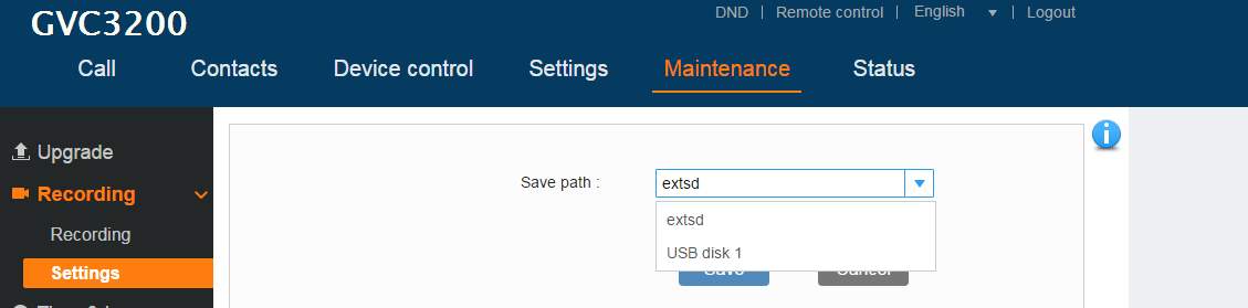
Search Recording File
Under GVC3200/GVC3202 web UI🡪Maintenance🡪Recording🡪Recording, in the “Search” field, users could enter a keyword to search for the available recording file.
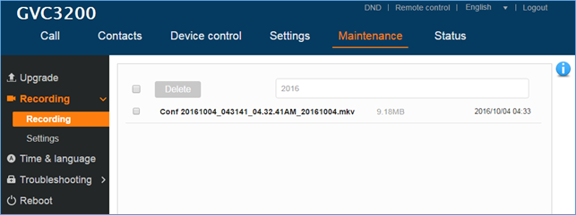
Maintenance/Time & Language
Parameters | Descriptions |
Assign NTP Server Address 1 | It is used to define the URL or IP address of the NTP server 1. The device may obtain the current date and time information from the server. The default setting is “us.pool.ntp.org”. |
It is used to define the URL or IP address of the NTP server 2. The default setting is empty. | |
Set Date | Manually set the current date for device. |
Set Time | Manually se the current time for device. |
Time zone | It is used to set the local time zone for the device. It covers the global time zones and user can selected the specific one from the drop-down list. |
Use 24-hour Format | Check/uncheck to display the time using 24-hour time format or not. For example, in 24-hour format, 13:00 will be displayed instead of 1:00 pm. The default setting is “Yes”. |
DHCP Option 42 Override NTP Server | It is used to set if the device will allow the DHCP offer overrides the NTP server address setting. If it set to “Yes”, the DHCP offer with Option 42 will override the device’s NTP server address setting. The default setting is “Yes”. |
DHCP Option 2 to Override Time Zone Setting | It is used to set if the device will allow the DHCP offer overrides the Time Zone setting. If it set to “Yes”, the DHCP offer with Option 2 will override the device’s time zone setting. The default setting is “No”. |
Date Display Format | It is used to set the format used to display the date. It can be selected from the drop-down list.
The default setting is MM/DD/YYYY. |
Language | Select the language displayed on the LCD from the drop-down menu. |
Maintenance/Troubleshooting
Parameters | Descriptions |
Logcat | |
Clear Log | It is used to clear the log files saved in device. |
Log Tag | It is used to configure the filter to display the specified process log file. |
Log Priority | It is used to select the log priority to display. It can be selected from the following:
The default setting is “Verbose”. |
Capture Trace | Press the START button to start capturing a trace, and press STOP to stop the capture process. The default setting is close. |
Trace List | Selects the existing capture file. Press the DELETE button on the right to delete file. |
View Trace | Click the “List” button to view the traces, which are listed according to time when the traces were captured. Click the trace name to download it to PC. The captures files are saved in FileManager🡪SD Card🡪ppp file. |
Press the START button to start capturing audio data and press STOP to end the capture process. The default setting is not enabled. Note: You can record up to 1 minute audio data. | |
Recording List | Choose the existing audio file. Click the “Delete” button on the right to delete this file. |
View Recording | Click on the “List” button to view. The captured audio data will be sorted by time. Click to download the data to the computer for analysis. Note: The audio data file will be saved under FileManager 🡪 Internal Storage 🡪 Recfiles folder. Users can also delete files under this folder. |
Enable Core Dump Generation | Configures whether to generate and save the core dump file when the program crashes. The default setting is “No”. |
Core Dump List | Select the existing core dump file in the drop-down box. Users could lick the “Delete” button on the right to delete the file. |
View Core Dump | Click the “List” button to view all existing core dump files. The files are listed in chronological order, users could click the file name to download the file to the local computer. |
Syslog | |
Syslog Server Address | The URL/IP address for the syslog server. |
Syslog Level | Selects the level of logging for syslog. The default setting is “None”. There are 4 levels: DEBUG, INFO, WARNING and ERROR. Syslog messages are sent based on the following events:
|
If set to “Yes”, the device will send SIP log in the syslog messages. The default setting is “No”. | |
Select H.323 syslog level in the dropdown menu. The default setting is “Off”, which means no H.323 related syslog information in syslog. The users can select syslog level from 1 to 10, with 10 being the highest level. | |
Ping | |
Target Host | Enter the target host and press “Start” to ping the host address. This can be used to test the reachability of a host in the network and measure the round-trip time for messages sent from the device to the destination host. |
Traceroute | |
Target Host | Fill in target host or IP address and click START to view details displayed below. This will output a list of traversed routers and measure transit delays of packets across the network. |
Developer Mode | |
Developer Mode | If turned on, ADB (Android Debug Bridge) function will be enabled on the device. The default setting is “Disabled”. This option is usually used for development purpose instead of normal usage. |
Remote diagnosis | |
Remote diagnosis | When users enable this feature, remote debugging and remote Web UI access will be allowed. The feature will be disabled automatically after 48h. |
Maintenance/Reboot
Users could click on “Reboot” to reboot the device, click on “Sleep” to go into sleep mode or click on “Shutdown” to turn off the device.
Contacts
Contacts/Contacts
- Contacts
Users could use contacts page from GVC320x Web UI🡪Contacts🡪Contacts to manage contacts entries.
Click on “Add” to add a new contact entry manually.
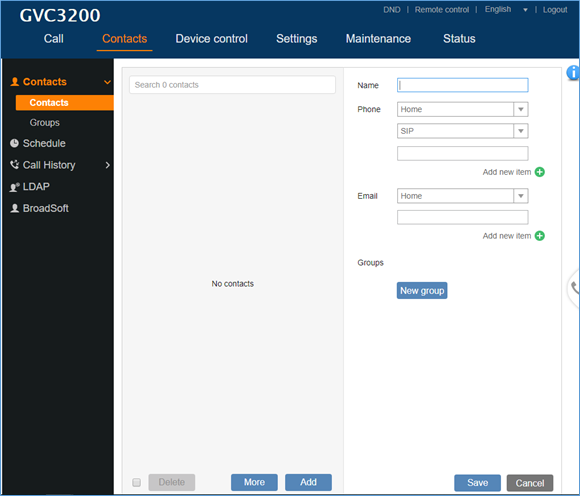
Parameters | Descriptions | |
Name | Specify the name of the contact entry. | |
Phone | Category | Specify the category of the phone number to enter. Available options are: Home, Mobile, Work, Fax, Work Fax, Home Fax, Pager, Other, Callback, Car, Company Switchboard, ISDN, Main, Other Fax, Radio, Telex, TTY TDD, Work Mobile, Work Pager, Assistant, MMS |
Account | Specify which account will be associated with the contact entry. It is the account used when dialing this contact. Available options are: SIP, IPVideoTalk, H.323. | |
Phone number | Enter the phone number of the contact. | |
Category | Specify the category of the email to enter. Available options are: Home, Work, Other, Mobile. | |
Enter the email address of the contact entry. | ||
Groups | Specify a group (if available) for the contact entry. Users can press “New Group” to create a new group. |
Press “More” button to “Import”, “Export” or “Download” contacts entries.
- Import
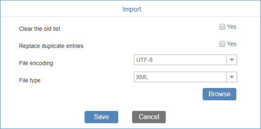
Table 4: Import Contacts Parameters
Parameters | Descriptions |
Clear the old list | If it is enabled, the previous contact records will be deleted when a new phonebook file is loaded into the device. If it is disabled, both the old contacts and new contacts will be kept in GVC320X. |
Replace Duplicate Entries | If it is enabled, when the phonebook file is imported to the device, the duplicated entries will be removed. If it is disabled, both the old contacts and new contacts will be kept in GVC320X. |
File Encoding | Select the encoding format for XML contact file. Available options: UTF-8, GBK, UTF-16, UTF-32, Big5, Big-HKSCS, Shift-JIS, ISO8859-1, ISO8859-15, Windows-1251, EUC-KR |
File Type | Select the file format for phonebook file import. The device supports xml, csv and vcard format. |
Browse | Select the file to import. |
- Export
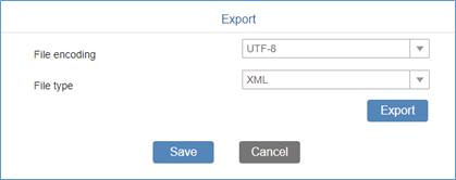
Table 5: Export Contacts Parameters
Parameters | Descriptions |
File Encoding | Select the encoding format for XML contact file. Available options: UTF-8, GBK, UTF-16, UTF-32, Big5, Big-HKSCS, Shift-JIS, ISO8859-1, ISO8859-15, Windows-1251, EUC-KR |
File Type | Select the file format for phonebook file import. The device supports xml, csv and vcard format. |
Export | Press “Export” button to export the contacts. |
- Download
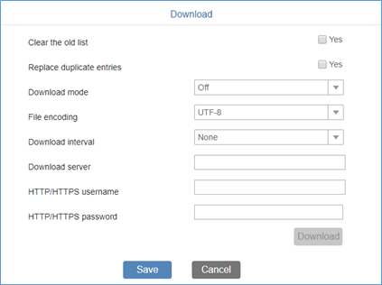
Table 6: Download Contacts Parameters
Parameters | Descriptions |
Clear the old list | If it is enabled, the previous contact records will be deleted when a new phonebook file is loaded into the device. If it is disabled, both the old contacts and new contacts will be kept in GVC320X. |
Replace Duplicate Entries | If it is enabled, when the phonebook file is imported to the device, the duplicated entries will be removed. If it is disabled, both the old contacts and new contacts will be kept in GVC320X. |
Download Mode | Select the phonebook download mode from TFTP, HTTP or HTTPS. |
File Encoding | Select the encoding format for XML contact file. Available options: UTF-8, GBK, UTF-16, UTF-32, Big5, Big-HKSCS, Shift-JIS, ISO8859-1, ISO8859-15, Windows-1251, EUC-KR |
Download Interval | Configure the time interval to download XML contact file. |
Download Server | Fill in the server URL or IP address to download the XML contact file to the device. |
HTTP/HTTPS Username | Configure the HTTP/HTTPS username for phone book downloading if it’s required by the server. |
HTTP/HTTPS Password | Configure the HTTP/HTTPS password for phone book downloading if it’s required by the server. |
Download | Press “Download” button to start downloading phonebook immediately. |
- Groups
Click on “Add” to add a new group.
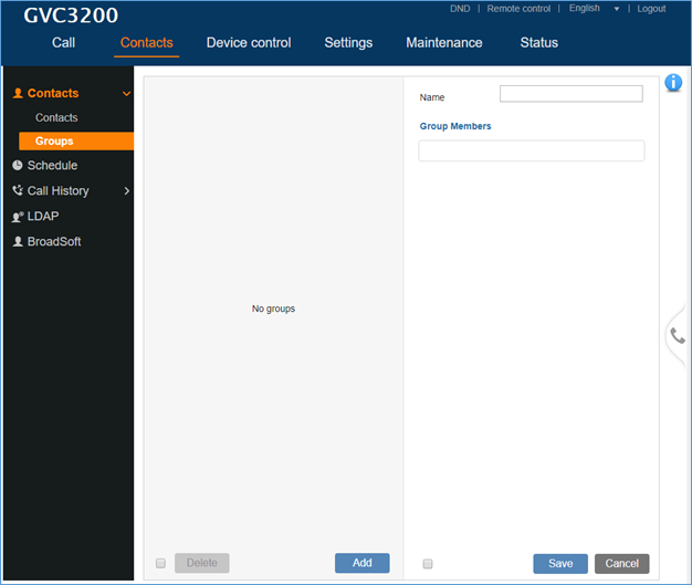
Parameters | Descriptions |
Name | Specify a name for the group. |
Group Members | Select members of the group. |
Contacts/Schedule
Users could use schedule meetings from GVC320X Web UI🡪Contacts🡪Schedule.
Click on “Add” to schedule a new conference.
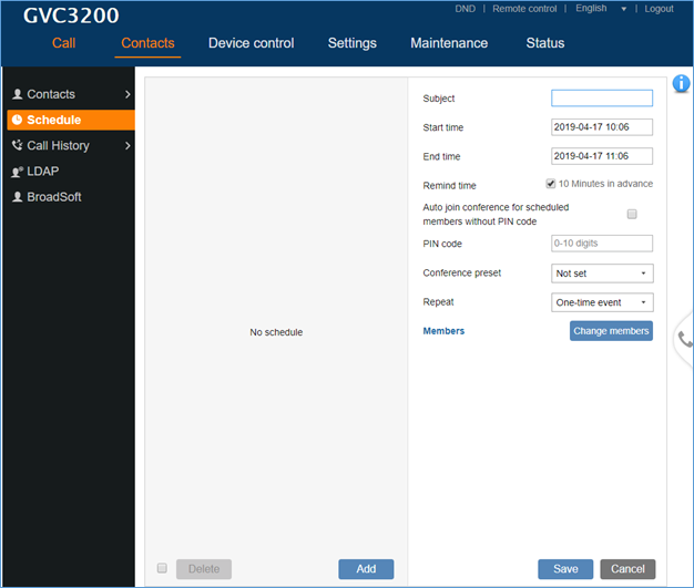
Parameters | Descriptions |
Subject | It is used to set the conference name to identify this conference. |
Start Time | It is used to configure the start time of the conference. |
End Time | It is used to configure the end time of the conference. |
Remind Time | It is used to configure whether to remind users in advanced. A prompt dialog box will pop up on GVC320X screen 10 minutes before the conference starts. |
Conference preset | It is used to select a camera preset when the scheduled conference starts, the GVC320X’s camera will be automatically placed to the preset position. Default is “Not set”. |
Repeat | Users could repeat the scheduled conference, to repeat the conference depending on the chosen option:
|
Members | Click on Change member to select and add participants to the conference. |
Contacts/Call History
Users could view Call History GVC320X Web UI🡪Contacts🡪Call History.
Call History 🡪 All shows all calls (outgoing, received, missed).
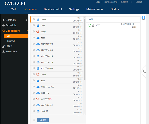
Call History 🡪 Missed shows only missed calls.
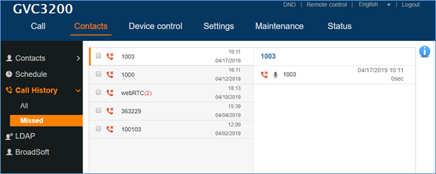
Contacts/LDAP
The users can configure LDAP client under web UI🡪Contacts🡪LDAP.
Parameters | Descriptions |
Connection Mode | It is used to select which protocol will be used for LDAP searching, LDAP or LDAPS. |
Server Address | It is used to configure the URI of the LDAP (Lightweight Directory Access Protocol) server. |
Port | It is used to configure the LDAP server port. The default LDAP port number is 389. |
Base DN | It is used to configure the LDAP search base. This is the location in the directory where the search is requested to begin. Example: dc=grandstream, dc=com ou=Boston, dc=grandstream, dc=com |
User Name | It is used to configure the bind “Username” for querying LDAP servers. Some LDAP servers allow anonymous binds in which case the setting can be left blank. |
Password | It is used to configure the bind “Password” for querying LDAP servers. The field can be left blank if the LDAP server allows anonymous binds. |
LDAP Name Attributes | It is used to configure the “name” attributes of each record which are returned in the LDAP search result. This field allows the users to configure multiple space separated name attributes. Example: gn cn sn description |
LDAP Number Attributes | It is used to configure the “number” attributes of each record which are returned in the LDAP search result. This field allows the users to configure multiple space separated number attributes. Example: telephoneNumber telephoneNumber Mobile |
LDAP Mail Attributes | It is used to configure the “mail” attributes of each record which are returned in the LDAP search result. Example: |
LDAP Name Filter | It is used to configure the filter used for name lookups. Examples: (|(cn=%)(sn=%)) returns all records which has the “cn” or “sn” field starting with the entered prefix; (!(sn=%)) returns all the records which do not have the “sn” field starting with the entered prefix; (&(cn=%) (telephoneNumber=*)) returns all the records with the “cn” field starting with the entered prefix and “telephoneNumber” field set. |
LDAP Number Filter | It is used to configure the filter used for number lookups. Examples: (|(telephoneNumber=%)(Mobile=%) returns all records which has the “telephoneNumber” or “Mobile” field starting with the entered prefix;
(&(telephoneNumber=%) (cn=*)) returns all the records with the “telephoneNumber” field starting with the entered prefix and “cn” field set. |
LDAP Mail Filter | It is used to configure the filter used for mail lookups. Example: (mail=%) |
LDAP Displaying Name Attributes | It is used to configure the entry information to be shown on phone’s LCD. Up to 3 fields can be displayed. Example: %cn %sn %telephoneNumber |
Max Hits | It is used to configure the maximum number of results to be returned by the LDAP server. If set to 0, server will return all search results. The default setting is 50. |
Search Timeout (ms) | It is used to configure the interval (in seconds) for the server to process the request and client waits for server to return. The default setting is 4000 seconds. |
LDAP Lookup When Dialing | It is used to set if allow the phone system to do the LDAP number searching when making outgoing calls. The default setting is “No”. |
Search LDAP For Incoming Call | It is used to set if allow the phone system to do LDAP number searching for incoming calls. The default setting is “No”. |
Contacts/BroadSoft
Parameters | Descriptions |
XSI | |
Authentication Type | Defines the authentication type in way of login or use SIP. If set to “Login Credentials”, please fill in Username and Password in the following options; if set to “SIP Credentials”, please fill in Username, User ID, and Password. The default setting is “SIP Credentials”. |
Server | Configures the BroadWorks Xsi server URI. If the server uses HTTPS, please add the header “HTTPS” ahead of the Server URI. For instance, “https://SERVER_URI”. |
Port | Configures the BroadWorks Xsi server port. The default port is 80. If the server uses HTTPS, set to 443. |
Action path | Customizes domain name for XSI request. If blank, XSI requests will be sent to configured XSI server URL (for instance: https://SERVER_URI). If specified, configured action path will be added to configured XSI server. (for instance: https://SERVER_URI/ACTION_PATH”. |
BroadWorks User ID | Determines the User ID for Broadsoft XSI server. |
SIP Authentication ID | Determines username for Broadsoft XSI server when Authentication Type is set to “SIP Credentials”. |
SIP Authentication Password | Determines password for Broadsoft XSI server when Authentication Type is set to “SIP Credentials”. |
Login Password | Specifies the password for the BroadWorks XSI query when Authentication Type is set to “Login Credentials”. |
Network Directories | |
Group Directory | Enables/disables the BroadWorks Xsi Group Directory features on the phone. The name filed is used to name the directory. If it keeps blank, the phone system will use the default name “Group” for it. |
Enterprise Directory | Enables/disables the BroadWorks Xsi Enterprise Directory features on the phone. The name filed is used to name the directory. If it keeps blank, the phone system will use the default name “Enterprise” for it. |
Group Common | Enables/disables the BroadWorks Xsi Group Common features on the phone. The name filed is used to name the directory. If it keeps blank, the phone system will use the default name “Group Common” for it. |
Enterprise Common | Enables/disables the BroadWorks XSI Enterprise Common features on the phone. The name filed is used to name the directory. If it keeps blank, the phone system will use the default name “Enterprise Common” for it. |
Personal Directory | Enables/disables the BroadWorks Xsi Personal Directory features on the phone. The name filed is used to name the directory. If it keeps blank, the phone system will use the default name “Personal Directory” for it. |
Missed Call Log | Enables/disables the BroadWorks Xsi Missed Call Log features on the phone. The name filed is used to name the directory. If it keeps blank, the phone system will use the default name “Missed” for it. |
Placed Call Log | Enables/disables the BroadWorks Xsi Placed Call Log features on the phone. The name filed used to name the directory. If it keeps blank, the phone system will use the default name “Outgoing” for it. |
Received Call Log | Enables/disables the BroadWorks Xsi Received Call Log features on the phone. The name filed used to name the directory. If it keeps blank, the phone system will use the default name “Incoming” for it. |
Others | |
Broadsoft Directory & Call Logs Update Interval (s) | Specifies how often the phone system sends HTTP/HTTPS query to the BroadWorks Xsp server to update the BroadWorks Call History. The default setting is 1800 seconds. |
Broadsoft Directory Hits | Determines how many entry results will be showed in each query. If it is configured, the phone system will add the header to the HTTP query. The valid range is from 1 to 1000. The default setting is blank, which means to use the server’s default value. |
Broadsoft Directory Order | Configures the BS contact order on the LCD. The order of contact categories on the Web GUI from top to bottom is same as the order from left to right on the BS contact app. Select one item and click the Up/Down arrow to adjust the order. |
Device Control
Video Control
Users could add preset and manipulate PTZ control on this page.
- Move the cursor to one configured preset to preview preset.
- Click one preset to apply the preset.
- Click the un-configured preset, and adjust via the PTZ control panel on the right, then save the configurations.
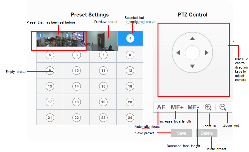
Audio Control
Parameters | Descriptions |
Ringtone Volume | Users can slide left or right to adjust ringtone volume. |
Media Volume | Users can slide left or right to adjust media volume. |
Device Ringtone | Select device ringtone from the dropdown list. |
Notification Ringtone | Select device notification ringtone from the dropdown list. |
Audio Device | Select the audio device that the GVC3200/GVC3202 will use for audio input and output during call or playing media. The options are “Auto”, “Bluetooth”, “USB” and “HDMI”.
The default setting is “Auto”. |
USB External Sound Card gain(dB) | TX gain(dB): The volume that GVC320x sends to other remote parties will be adjusted. |
RX gain(dB): The volume that GVC320x receives from other remote parties will be adjusted. | |
Call Progress Tones: Ring Back Tone Busy Tone Reorder Tone Confirmation Tone Call-waiting Tone | Using these settings, users can configure ring or tone frequencies based on parameters from the local telecom provider. By default, they are set to the North American standard. Frequencies should be configured with known values to avoid uncomfortable high pitch sounds. Syntax: f1=val, f2=val [,c=on1/off1[-on2/off2[-on3/off3]]]; (Frequencies are in Hz and cadence on and off are in 10ms) |
Ring Back Tone: Users can configure ring back tone which is the tone the caller will hear before the callee answers the call. The default value: f1=440@-19,f2=480@-19,c=2000/4000; | |
Busy Tone: Users can configure busy tone which will be heard if the callee is busy or on DND. The default value: f1=480@-24,f2=620@-24,c=500/500; | |
Reorder Tone: Users can configure reorder tone which will be heard when the call fails to be established such as wrong account number is dialed, or the call is timed out. The default value: f1=480@-24,f2=620@-24,c=250/250; | |
Confirmation Tone: Users can configure confirmation tone which will be heard when the callee enables call recording function or when the SIP account fails to register. The default value: f1=350@-11,f2=440@-11,c=100/100-100/100-100/100. | |
Call Waiting Tone: Users can configure call waiting tone when there is another incoming call during the call. The default value: f1=440@-13,c=300/2000-300/2000-0/0. | |
Call-Waiting Tone Gain | This configures the call-waiting tone gain. By default, they are set to the North American standard. Users could select "Low", "Medium" or "High". The default setting is "Low". |
Ring Cadence | Configure the default ring cadence for the ring back tone. The default setting is c=2000/4000. |
Status
The Status page lists Account Status, Peripheral Status, Network Status, System Info and Remote Control status. Please also refer to chapter Status in GVC3200/GVC3202 LCD SETTINGS.
Status/Account Status
Parameters | Descriptions |
Account | It lists the accounts available on device. |
Number | It displays the SIP User ID of the account (if applicable). |
SIP Server | It displays the SIP server address for the account (applicable to SIP account only). |
Status | It shows the registration status of the account: Registered or Unregistered. |
Status/Peripheral Status
Connection status for each interface is displayed with different icons here. The icon in green indicates “Connected” and the icon in grey means “Not Connected”.
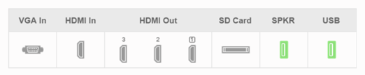
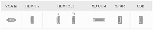
Status/Network Status
Parameters | Descriptions |
MAC Address | This is the global unique ID of device. |
Address Type | Displays how the device obtains IP address. It could be DHCP, Static IP or PPPoE. |
IP Address | IP Address obtained or configured on the device. |
Subnet Mask | Subnet mask obtained or configured on the device. |
Gateway | The gateway address obtained or configured on the device. |
DNS Server 1 | DNS Server 1 obtained or configured on the device. |
DNS Server 2 | DNS Server 2 obtained or configured on the device. |
NAT Type | The type of NAT connection used by the device. |
Status/System Info
Parameters | Descriptions |
Product Model | Device model: GVC3200 or GVC3202. |
Hardware Version | Device hardware version. |
Part Number | Device Part Number (PN). |
System Version | Device system version. This is the firmware version on the device. When upgrading firmware, this is the version number to refer to. |
Recovery Version | Device recovery version. |
Boot Version | Device boot version. |
Kernel Version | Device kernel version. |
Codec System Version | Device codec system version. |
Codec Boot Version | Device codec boot version. |
Codec Kernel Version | Device codec kernel version. |
ISP Version | ISP version. |
Android™ Version | Device Android™ version. Currently it’s 4.4.2. |
System Up Time | Device system up time since the last reboot. |
Status/Remote Control
Parameters | Descriptions |
Hardware Version | The remote control hardware version. |
Software Version | The remote control software version. |
Touchpad Version | The remote control touchpad version. |
Remote Control Battery | The remote control battery status. |
FIRMWARE UPDATE
GVC3200/GVC3202 supports software upgrade via the following methods:
- Manually upload firmware file to upgrade (for applicable firmware versions only).
- Upgrade via TFTP firmware server
- Upgrade via HTTP/HTTPS firmware server
No Local TFTP/HTTP Servers
Service providers should maintain their own firmware upgrade servers. For users who do not have a TFTP/HTTP/HTTPS server, some free Windows version TFTP servers are available for download from:
http://www.solarwinds.com/products/freetools/free_tftp_server.aspx
Please check our website at http://www.grandstream.com/support/firmware for latest firmware.
Upgrade GVC3200/GVC3202 via TFTP Server
Here is the instruction to upgrade GVC3200/GVC3202 via TFTP server:
- Unzip the firmware files and put all of them in the root directory of the TFTP server.
- Connect the PC running the TFTP server and the GVC3200/GVC3202 device to the same LAN segment.
- Launch the TFTP server and go to the File menu🡪Configure🡪Security to change the TFTP server’s default setting from “Receive Only” to “Transmit Only” for the firmware upgrade. (This step may be different depending on the TFTP server software you are using).
- Start the TFTP server.
- On the GVC3200/GVC3202 web UI🡪Maintenance🡪Upgrade page, configure TFTP as the “Firmware upgrade mode” and enter the IP address of the PC in “Firmware server path” field.
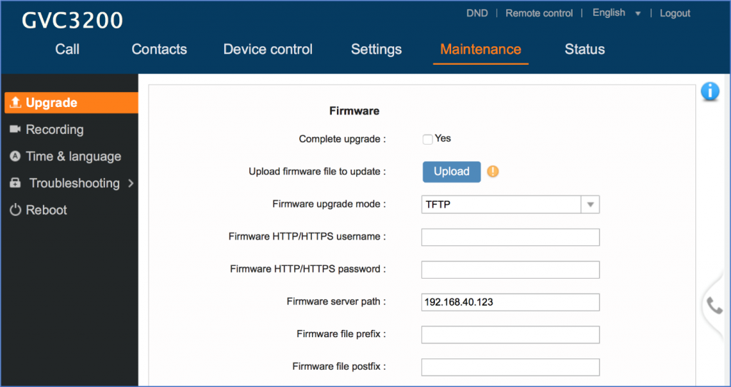
6. Save and apply the change. Then reboot the device.
Please note end users can also choose to download a free HTTP server from http://httpd.apache.org/ or use Microsoft IIS web server.
Provisioning and Configuration File Download
Grandstream SIP Devices can be configured via the Web Interface as well as via a Configuration File (binary or XML) through TFTP or HTTP/HTTPS. The “Config Server Path” is the TFTP, HTTP or HTTPS server path for the configuration file. It needs to be set to a valid URL, either in FQDN or IP address format. The “Config Server Path” can be the same or different from the “Firmware Server Path”. A configuration parameter is associated with each particular field on the web configuration page. A parameter consists of a Capital letter P and 2 to 4-digit numeric numbers. i.e., P2 is associated with the “Admin Password” in the Web GUI🡪Maintenance🡪Web/SSH Access page. For a detailed parameter list, please refer to the corresponding firmware release configuration template in the following link: http://www.grandstream.com/support/tools
When the GVC3200/GVC3202 boots up, it will issue TFTP or HTTP request to download a configuration XML file named “cfgxxxxxxxxxxxx” followed by “cfgxxxxxxxxxxxx.xml”, where “xxxxxxxxxxxx” is the MAC address of the device, i.e., “cfg000b820102ab” or “cfg000b820102ab.xml”. If downloading “cfgxxxxxxxxxxxx.xml” file is not successful, the provision program will download a generic cfg.xml file. The configuration file name should be in lower case letters.
For more details on XML provisioning, please refer to the following document:
https://documentation.grandstream.com/knowledge-base/sip-device-provisioning-guide/
Users could find XML configuration file generator tool and user guide in the following web page. Please use the XML configuration file generator to generate the XML configuration file for your devices’ provisioning.
http://www.grandstream.com/support/tools
Remote Control Upgrade
The GVC3200/GVC3202 remote control firmware is embedded with GVC3200/GVC3202 firmware. When GVC3200/GVC3202 detects a new firmware version for the connected Bluetooth remote control, a prompt box will pop up on screen to remind users whether to upgrade the remote control. Tap on OK to upgrade, or tap on CANCEL to reject.
Users could also check remote control firmware update manually in LCD menu🡪Settings🡪Status🡪Remote Control and click “Check for Updates”. If there is a new version, follow the prompts on the screen to download remote control update and upgrade. Network connection and remote control connection will be temporarily lost during remote control upgrade. Both connections will be restored automatically once upgrading is done.
RESCUE MODE
When users power cycle the GVC3200/3202 device during upgrading process, the device can be recovered by the “Rescue Mode”.
a). The Rescue Mode will be triggered on next rebooting when users power cycle the GVC3200/3202 device during upgrading process as the figure shows below:
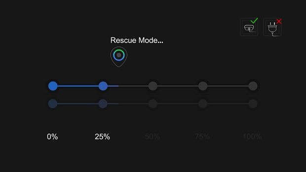
b). When the GVC320x device goes into the Rescue Mode, users should see the figure below. If the network is connected, the device will continue to download and upgrade the firmware automatically.
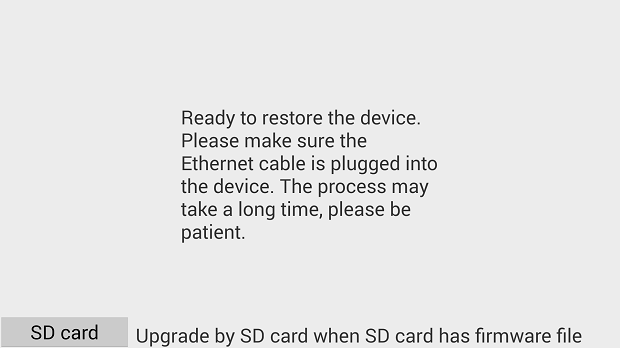
c). If the network is not connected, users can use the mouse to select “SD Card” or “Manual” to recover the device.
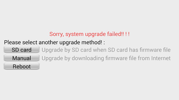
- Select “SD Card”.
Users could insert SD card with GVC32XX_rescue.bin firmware file to upgrade the GVC320x device. The device will be upgraded automatically via SD card.
2. Select “Manual”.
Please make sure that the Ethernet cable is plugged into the GVC320x device, and users need to configure the Internet Settings in the device to upgrade the GVC320x device.
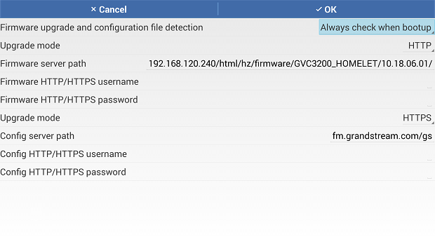
3. Select “Reboot”.
If users select “Reboot” option, the GVC320x device will enter “Rescue Mode” again.
FACTORY RESET
Users could reset GVC3200/GVC3202 to factory settings via the following ways:
- Reset via LCD menu
- Reset via GVC3200/GVC3202 web UI
- Reset via the reset pin hole on the back panel of GVC3200/GVC3202.
Factory reset will delete configuration information and syslog information.
Reset via LCD Menu
Go to GVC3200/GVC3202 LCD idle screen🡪Settings🡪Maintenance🡪Factory Reset, click on the “Reset” button to bring up the prompt box as shown below. Click “OK” to reboot the device and restore factory settings.
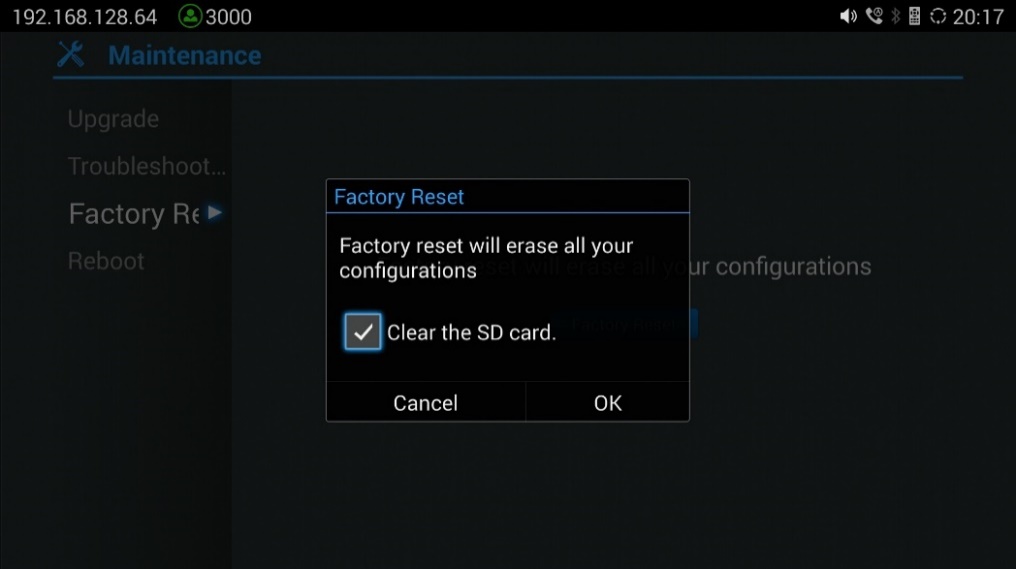
Reset via Web UI
- Go to GVC3200/GVC3202 Web GUI🡪Upgrade and the “Factory Reset” option is on the bottom of the page.

2. Click the “Reset” button to bring up the prompt box as shown below. Click “OK” to reboot the device, and restore factory settings.

If “Clear the SD card” is selected, the user’s files such as pictures and music files that are previously saved in the GVC3200/GVC3202 internal SD card will be also removed after factory reset.
Reset via Reset Pin Hole
There is a Reset pin hole on the back panel of GVC3200/GVC3202. To reset the device, use a small pin to hold against the Reset pin hole for more than 10 seconds to restore to factory settings.
EXPERIENCING THE GVC3200/GVC3202
Please visit our website: http://www.grandstream.com to receive the most up-to-date updates on firmware releases, additional features, FAQs, documentation and news on new products.
We encourage you to browse our product related documentation, FAQs and User and Developer Forum for answers to your general questions. If you have purchased our products through a Grandstream Certified Partner or Reseller, please contact them directly for immediate support.
Our technical support staff is trained and ready to answer all of your questions. Contact a technical support member or submit a trouble ticket online to receive in-depth support.
Thank you again for purchasing Grandstream Video Conferencing System, it will be sure to bring convenience and color to both your business and personal life.
* Android is a trademark of Google Inc.

HDMI, the HDMI Logo, and High-Definition Multimedia Interface are trademarks or registered trademarks of HDMI Licensing LLC in the United States and other countries.
CHANGE LOG
This section documents significant changes from previous versions of the GVC3200/GVC3202 user manuals. Only major new features or major document updates are listed here. Minor updates for corrections or editing are not documented here.
Firmware Version 1.0.3.69
- Added Line in/out audio priority in GVC320x “Audio Priority” menu. [Device Control]
- Added “Remote Diagnosis” module on GVC320x Web UI. [Maintenance/Troubleshooting]
- Add configuration of “Minimum TLS Version” and “Maximum TLS Version” on GVC320x’s Web UI. [Settings/Security Settings]
Firmware Version 1.0.3.64
- No major changes.
Firmware Version 1.0.3.62
- Added support to upload server customer certificate file on GVC320x. [Import Custom Certificate]
- Added common Layout mode configuration on GVC320X’s WEB GUI. [Settings/SIP/Call][Settings/IPVideoTalk/Call][Settings/BlueJeans/Call][Settings/H.323/Call]
- Added Broadsoft XSI Contacts and Call History. [Contacts/BroadSoft]
- Supported new remote control for GVC3200 2.3A+ and GVC3202 1.1A. [Settings/General Settings]
- Added remote control model option. [Settings/General Settings].
Firmware Version 1.0.3.51
- Added “Record” feature on the Troubleshooting Menu. [Record]
Firmware Version 1.0.3.49
- No major changes.
Firmware Version 1.0.3.46
- Optimized OPUS codec upstream performance.
Firmware Version 1.0.3.45
- Added TR-069 feature in GVC320x, and added the configuration page on the Web UI. [TR-069]
Firmware Version 1.0.3.38
- Added DND forwarding feature for SIP calls [Enable DND forward]
- Added an option to select G722.1c as preferred vocoder for the account to use during the call. [Preferred Vocoder]
- Added support for carrying BFCP media information in initial INVITE packet [INVITE with media info]
Firmware Version 1.0.3.24
- No major changes.
Firmware Version 1.0.3.16
- Added option to adjust USB External Sound Card TX and RX gain on GVC320x WebUI. [USB External Sound Card gain(dB)]
- Added coredump related settings to view, edit and download coredump file. [Debug]
- Added option “Enable Presentation Automatically When HDMI/VGA plugged” to switch presentation mode automatically. [Enable Presentation Automatically When HDMI/VGA Plugged]
Firmware Version 1.0.3.8
- Added IPv6 support. [Ethernet]
- Added recording storage selection under web UI🡪Maintenance🡪Recording🡪Settings. [Recording Storage Selection]
- Added recording search function under web UI🡪Maintenance🡪Recording. [Search Recording File]
- Added conference preset settings for schedule. [Contacts/Schedule]
- Added option “Auto mute on entry”. [Auto mute on entry]
- Added DHCP Option 132 and DHCP option 133 support. [DHCP VLAN override]
- Added Video packetization mode for SIP account and BlueJeans account. [Packetization-mode]
- Added GUI customization settings for using CUST file. [CUST File]
- Added option “Use Grandstream GAPS” for config file downloading. [Config]
- Added option “Validate Certification Chain” under web UI🡪Settings🡪SIP [Validate Certification Chain]
- Added support for users to upload trusted CA certificate. [Trusted CA Certificates]
- Added option “HDMI2 out resolution” in web UI🡪Settings🡪Peripheral. [HDMI Settings]
Firmware Version 1.0.1.74
- Updated size limitation of each recording file size from 1G to 1.9G. [Maintenance/Recording]
- Updated Grandstream GAPS system to provision default configuration on local GVC3200/GVC3202 device [Maintenance/Upgrade] [Upgrade] [FIRMWARE UPDATE]
Firmware Version 1.0.1.65
- Added IPVideoTalk account settings. [Settings/IPVideoTalk/General] [Settings/IPVideoTalk/Call]
- Added screen lock password options under web UI to set, edit and delete screen lock password. [Settings/Security Settings]
- Added options “H.264 payload type”, “H.264 image size”, “Video bit rate” and “Video frame rate” for H.323 account. [Settings/H.323/Codec]
- Added ability to choose any configured preset as initial preset in the drop-down menu in addition to “Default” and “Latest Position”. [Camera]
- Added H.460.18/19 support for H.323 so that H.323 account on GVC3200/GVC3202 can make IP calling through public Internet. [Settings/H.323/General]
Firmware Version 1.0.1.58
- Added H.323 account settings. [Settings/H.323/General] [Settings/H.323/Codec] [Settings/H.323/Call]
- Added H.323 syslog setting. [H.323 Syslog Level]
- Added “Call” settings under LCD menu🡪Settings🡪Accounts. [Call]
Firmware Version 1.0.1.48
- Added GVC3202 in the document.
- Added option “SIP User-Agent” in web UI. [SIP User-Agent]
- Added option “Filter Characters” in web UI. [Filter Characters]
- Added option “Secondary SIP Server” in web UI. [Secondary SIP Server]
- Added option “Tertiary SIP Server” in web UI. [Tertiary SIP Server] [Tertiary SIP Server] [Tertiary SIP Server] [Tertiary SIP Server]
- Added option “RTP IP Filter” in web UI. [RTP IP Filter]
- Added Opus codec. [Preferred Vocoder] [Opus Payload Type]
- Added option “Video FEC Mode” in web UI. [Video FEC Mode]
- Added option “Presentation Video Frame Rate”. [Presentation Video Frame Rate]
- Added option “BFCP Transport Protocol” in web UI. [BFCP Transport Protocol]
- Added option “Turn Server Username” “TURN Server Password” in web UI. [TURN Server Username] [TURN Server Password]
- Added option “Assign NTP Server Address 2” in web UI. [Assign NTP Server Address 2]
- Added LDAP Contacts support. [Contacts/LDAP]
- Separated firmware server and config server configuration on the device. [Maintenance/Upgrade]
- Added option “Use First Matching Vocoder in 200OK SDP”. [Use First Matching Vocoder in 200OK SDP]
- Added proxy settings under LCD settings🡪Network. [Proxy]
- Added option “Audio Priority” in LCD settings🡪Audio. [Audio Priority]
- Added option “HDMI Color Mode” under LCD settings🡪Peripheral🡪HDMI settings. [HDMI Settings]
- Added option “Codec Negotiation Priority”. [Codec Negotiation Priority]
- Added option “Send SIP Log”. [Send SIP Log]
Firmware Version 1.0.1.5
- This is the initial version.