


Introduction
Stacking is a horizontal virtualization technology that simplifies network configuration and management by connecting multiple stackable switches together through cable connections and merging them virtually into a single device. Combined with cross-device link aggregation technology, it not only achieves high-reliability backup of devices and links, but also avoids Layer 2 loops. Compared with STP loop protection. With stacking feature enabled, the logic topology is clearer and the link utilization is more efficient.
Please refer to the Supported devices section to view the switch models that support the stacking feature.
Important Considerations
Before configuring stacking for GWN78xx switches, please ensure you meet the following requirements:
Firmware & System Requirements:
- Identical Models: Only switches of the exact same model can form a stacking system.
⚠️ Important Note: Models with and without “P” (PoE) are considered entirely different models. For example, a GWN7816 cannot be stacked with a GWN7816P. They must be an exact match.
- Firmware Synchronization: All switches must run the same firmware version number. If a switch joins with an inconsistent version, it will be intelligently upgraded to match the master device after the stack is established.
Maximum Supported Devices:
Stacking limits depend on the specific switch model. Please refer to the table below:
| Maximum Devices in Stack | Supported Switch Models |
| Up to 8 Devices | GWN7832, GWN7831, GWN7816(P), GWN7806PL Pro, GWN7806PH Pro |
| Up to 4 Devices | GWN7830, GWN7813(P), GWN7812P, GWN7811(P), GWN7806(P) |
Port & Speed Requirements
- Eligible Stacking Ports: Only the last 4 SFP+ optical ports on the switch can be added to the stack.
- Exception: For the GWN7811(P), only its 2 SFP+ ports can be used.
- Port Speed: The connection rate must be strictly set to 10Gbps on all stacking ports.
Stacking Topology
When it comes to stacking, the GWN78xx network switches support two types of network typologies:
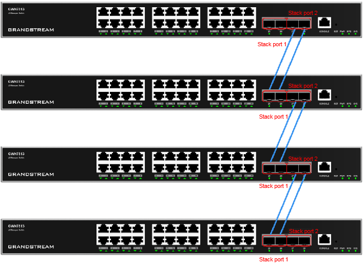
- Chain Topology: The switches are connected in a linear fashion, where each switch links to the next in sequence. This topology works best for small-scale setups where redundancy isn’t a priority. Its main advantage is ease of setup and expansion, making it straightforward for basic networks. However, it has a significant downside: a single point of failure, where if one switch or link fails, all downstream devices lose connectivity.
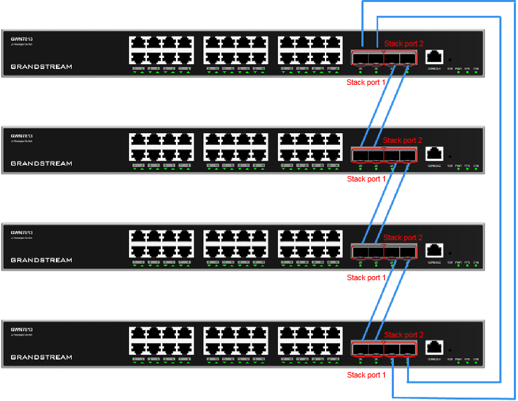
- Ring Topology: In this setup, the connected switches form a loop, with the last switch wired to the first, creating a circular path. This topology is ideal for situations where high redundancy is critical, as the loop ensures continuous data flow even if one link fails. The main advantage is its built-in failover mechanism, offering better fault tolerance. However, it can be more complex to configure and maintain compared to simpler topologies.
Choosing Between Ring and Chain Stacking Modes
Redundancy and Failover
- Ring Mode offers superior redundancy at the switch level. If one switch fails (e.g., hardware damage), traffic can reroute through the ring, and maintain uptime.
- Chain Mode lacks switch-level redundancy — a failed middle switch disrupts the stack.
- At the link level, both modes support dual-port links between switches. If one link fails, the second maintains stack communication.
Throughput
- Ring Mode can optimize traffic paths, and improve performance.
- Chain Mode requires traffic to pass through all intermediate switches, this can increase latency.
Deployment Recommendations
2 Switches:
- No functional difference between Ring and Chain.
- Best Practice: Use all 4 SFP+ ports for maximum bandwidth and link redundancy.
(GWN7811(P)/7821P: only 2 ports are stack-capable)
3 or 4 Switches:
- Preferred: Use Ring Mode (2 links per neighbor) for redundancy and performance — if cabling allows.
- Chain Mode: Acceptable for linear physical layouts with cable constraints. where users are forced to use linear cabling and the distance between the switches is large.
- (GWN7811(P)/7821P: can only form a 1-link stack with each neighbor)
Stacking Configuration
The GWN78xx Switches support to configure the stacking feature through two different methods:
In the example below, we will configure the stacking feature using the GWN7813 switch model, the same principle will be applied on the other supported switch models, please refer to [Supported Devices] section for more information on the devices and their corresponding ports for configuration.
CLI Configuration
Please follow the below steps for a correct configuration:
- Configure a stack ID: The ID of each device that joins the stack must be unique, otherwise it cannot be added to the stack.
Switch(config)# stack member 1 renumber <renumber-id>- Configure stack priority: The higher the value, the higher the priority.
Switch(config)# stack member priority <value>- Configure the stack port
Switch(config)# interface stack-port <member-id>/<port-id>
Switch(config-stack-port)# port interface Ethernet <member-id>/0/<port-id>- View the Stack Configuration
show stack configuration - Example
MemberID     NewID        Stack-Port1              Stack-Port2

—————————————————————————–

2 2 Ethernet2/0/9 Ethernet2/0/12WebUI Configuration
Please follow the below settings:
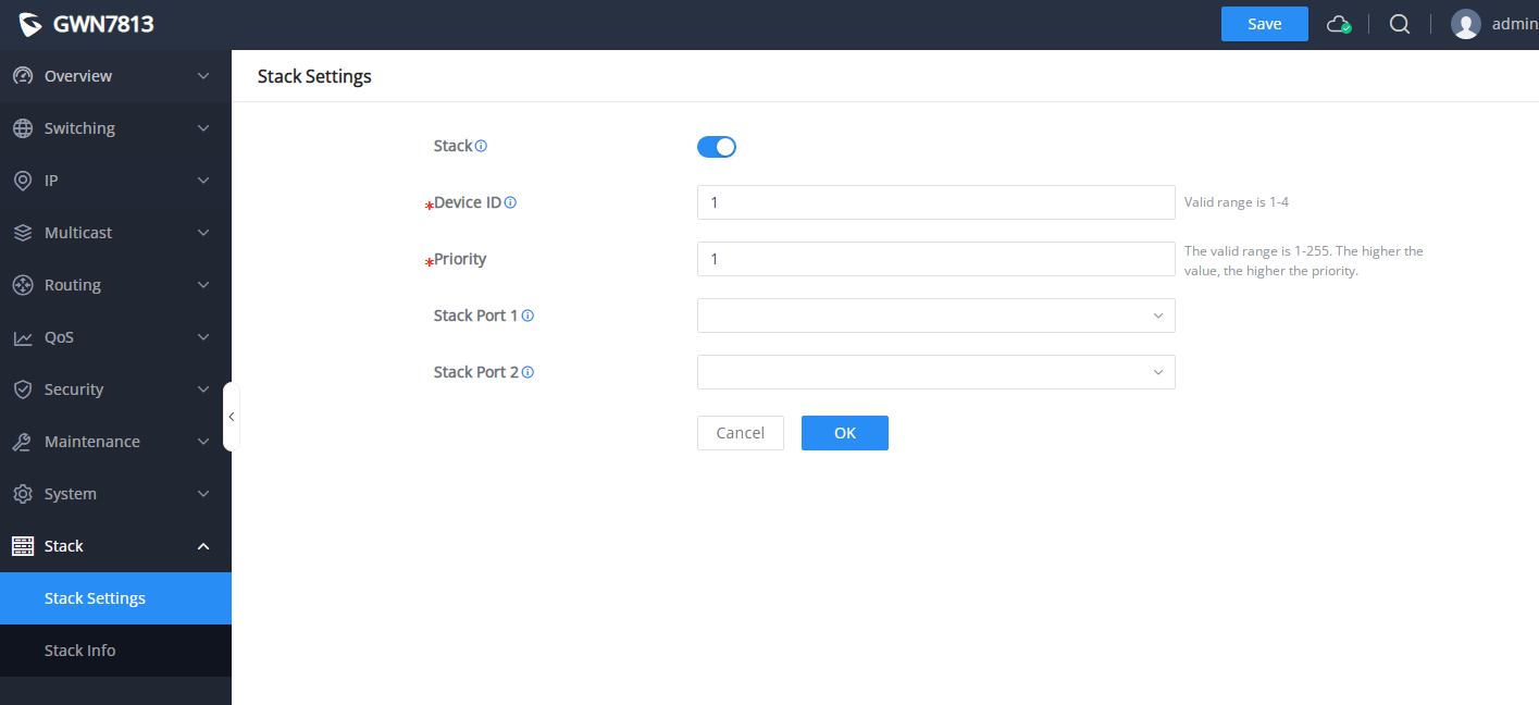
- Go to Stack => Stack Settings, Set the values of the device ID, priority, Stack port 1 and Stack port 2 on the web UI.
After the preceding configurations are complete, you can view the stack configurations to confirm the configuration from the CLI
Switch# show stack configuration
MemberID     NewID        Stack-Port1              Stack-Port2
-----------------------------------------------------------------------------
2            2            Ethernet2/0/25            Ethernet2/0/27
Wiring the switches
Cross-connect the switches between the member switches, and power them on.
Stacked elections
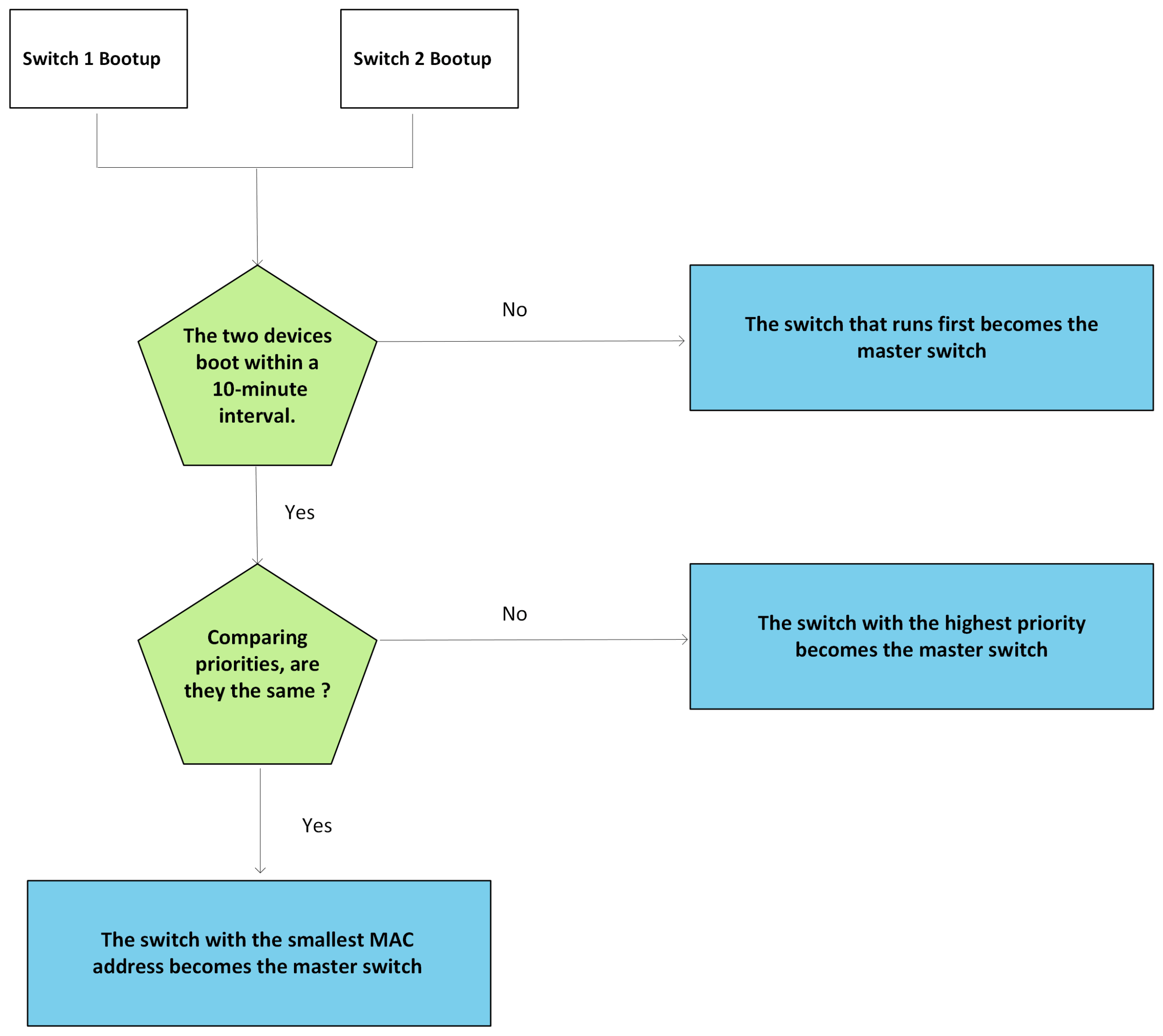
When a stack is established, member devices send stack competition packets to each other to elect the main switch. The role of the master switch is determined by three factors: switch boot time, switch stack priority, and MAC address of the switch. The specific election rules are as follows:
- At startup, the first switch powered on becomes the master switch, and the second switch powered on becomes the standby switch.
- The switch with the highest stacking priority is designated as the primary switch, while the switch with the second-lowest priority becomes the standby switch.
- If stack priorities are equal, the switch with the smallest MAC address is elected as the primary switch, and the one with the second-smallest MAC address becomes the standby switch.
Topology connection
After the master switch election is complete, the master switch collects information about all member switches and calculates the topology.
Steady-state operation
After the master switches calculate the topology information, it synchronizes the topology information of the entire stack system to all member switches and elects a standby switch. The rules for the election of a standby virtual Switch are as follows:
- When comparing stack priorities, the switch with the highest priority becomes the standby switch.
- If priorities are equal, the switch with the smaller MAC address is assigned as the standby switch.
Configure synchronization
The stack uses a strict configuration synchronization mechanism to ensure multiple switches operate as a single network device.
The configuration file consists of:
- Global configuration — settings applicable to all stack members, such as IP addresses and VLAN interfaces.
- Interface configuration — settings specific to each member switch’s interfaces, such as port VLAN assignments.
When the stack is formed, each member switch boots with its own configuration. Once started, standby and secondary switches synchronize their configurations from the master switch in batches. New devices added to the stack receive their configuration via this synchronization process.
While running, the master switch manages and instantly synchronizes all user configuration changes across member switches, maintaining consistency throughout the stack.
This instant synchronization ensures that all switches share the same configuration file, allowing seamless operation even if the primary switch fails.
Viewing the Stack Information
Once the stack is established, all member devices operate as a single virtual device, with the master switch managing the collective resources. Access to the stack for management and maintenance can be done via any member device; however, all sessions actually connect to the master switch, which serves as the configuration and control center.
After configuring the master, it synchronizes relevant settings to subordinate switches to maintain configuration consistency across the stack.
You can access the stack system through:
- Local login: via the console port of any member device
- Remote login: via the Layer 3 interface of any member device using HTTPS, Telnet, SSH, etc.
Stack system information can be viewed through the CLI or Web GUI.
View via CLI
To view the stack device list:
GWN7831(config)# do show stack - Example:
Stack enable: True
 	Stack topology type: Ring
 Stack system MAC: C0:74:AD:DA:D8:04
 Member     Role       MAC address          Priority   Device type
 -----------------------------------------------------------------
 * +3        Primary     C0:74:AD:DA:D8:04    1          GWN7813
   4       Secondary   C0:74:AD:E3:EA:9C    1          GWN7813
   5       Subordinate  C0:74:AD:E3:E9:CC    1          GWN7813
 -----------------------------------------------------------------
 * indicates the device is the primary.
 + indicates the device through which the user logs in.
To view the stack topology:
GWN7831(config)# do show stack topology - Example:
                Stack-Port1            Stack-Port2
 	MemberID    Link       Neighbor    Link       Neighbor
 	---------------------------------------------------------------------------
 3           Up         4           Up         5
 4           Up         5           Up         3
 5           Up         3           Up         4
View via the web GUI
After you log in to the web GUI by using the IP address of the main switch, you can view the stack system information in the Overview → System Info in the left-side navigation pane.
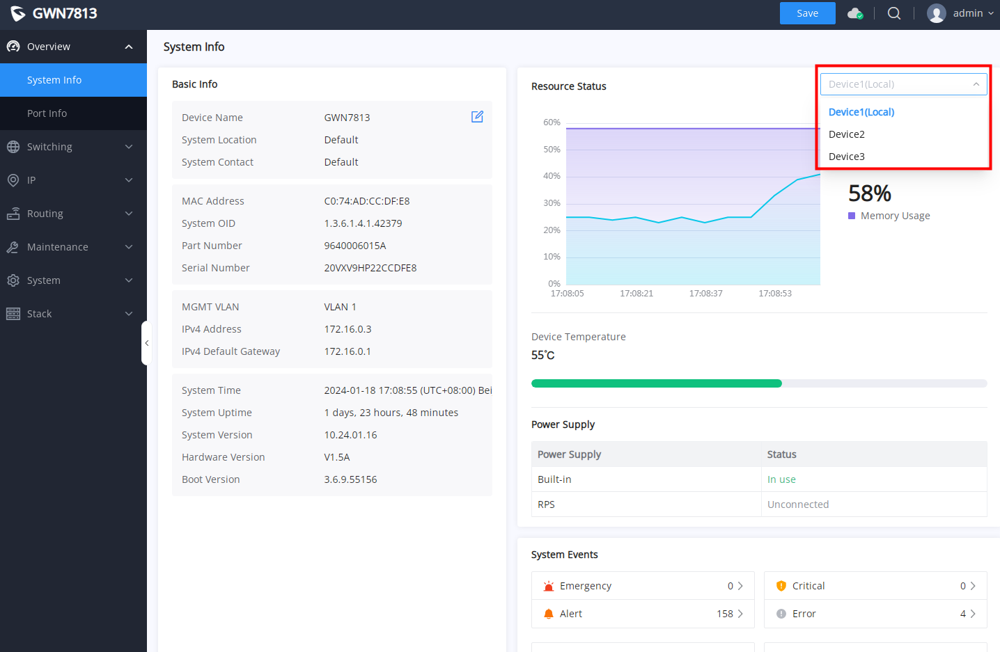
Click on Overview → Port Info, to view local device ports and stacked devices ports:
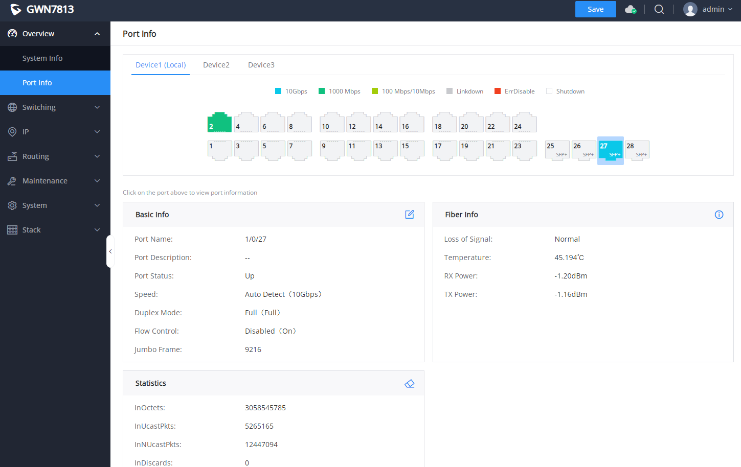
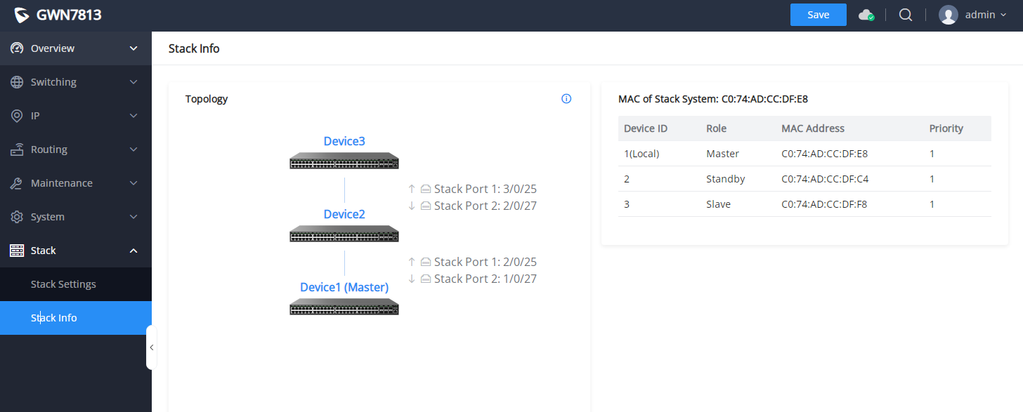
For more information about stacks, go to Stack → Stack Info to view the topology and device list.
Functional configuration
After logging in to the stack system, you can configure switch functions through the CLI or Web GUI. Not all switch functions are fully supported by the stack, the below mentioned ones on the tables are the supported ones:
Overview | System Information |
Port Information | |
Switching | Basic port configuration |
Port Group | |
Port Statistics | |
Loopback Detection | |
Port Auto Recovery | |
Ling Aggregation | |
MAC Address Table: | |
VLAN | |
Voice VLAN | |
STP | |
IP | VLAN IP Interface |
DHCP Server | |
DHCP Relay | |
ARP Table | |
Neighbor Discovery | |
DNS | |
Routing | Routing Table |
Static Routes | |
QoS | Port Priority |
Priority Mapping | |
Queue Schedule | |
Queue Shaping | |
Rate Limit | |
Security | Storm Control |
Port Security | |
Port Isolation | |
IP Source Guard | |
IPv6 Source Guard | |
Anti Attack | |
DAI | |
RADIUS | |
TACACS+ | |
AAA | |
DHCP Snooping | |
DHCPv6 Snooping | |
PoE | PoE |
Maintenance | Upgrade |
Diagnosis, including log, Ping, Traceroute, Mirroring, Fiber Module, Copper Test, and One-click Debugging | |
Backup & Restore | |
LLDP&LLDP-MED | |
EEE | |
System | Basic Settings |
Access Control | |
User Management | |
Time Policy | |
Stack | Stack Settings |
Stack Info | |
Others | mDNS |
CPU Protection |
Stacking support features
Stacked LED indicators
You can use the LED indicator of the device to determine the construction status of the stacking system. See the table below for details:
LED indicator | Indicator status | LED action |
System indicator (3-color light). | Yellow flashing | During stack establishment, including master-slave election and first-time configuration synchronization |
Solid yellow | When the stack is established, the master switch is established | |
Solid blue | When the stack is established, the slave switch is running normally | |
Flashing blue | Subsequent synchronization of the configuration from the switch | |
Solid red | Failed to establish a stack from the switch | |
Stack port indicators (monochromatic except for GWN7832) | Flashes green (blinking frequency 0.03125 seconds). | An error message is displayed for connecting a stack port, for example, stack port 1 is connected to stack port 1 |
Stacked LED indicators
Q&A – Common Causes of Stacking Failure
Inconsistent Device Models:
Stacking is only supported between compatible models. Mixing different hardware platforms or incompatible series will cause the stack to fail during initialization.
Firmware Version Mismatch:
All switches in the stack must run the same firmware version. If an intelligent upgrade is used to align firmware versions and the upgrade fails on one or more devices, the stack formation will also fail.
Improper Stack Port Connections:
Stack ports must be properly cross-connected between devices in a ring or chain topology. Incorrect cabling (e.g., connecting both ports to the same switch or leaving links open in a ring setup) will prevent the stack from forming.
Duplicate Device IDs:
Each member switch must have a unique device ID. Duplicate IDs cause conflicts in stack role assignments and prevent normal operation.
Unsupported Optical-to-Power Module Usage:
Using non-standard modules such as optical-to-power converters on stack ports can disrupt link negotiation or cause instability, leading to stack failure.
Insufficient Stack Port Bandwidth:
Stack ports must support a minimum of 10Gbps link speed. If the physical link speed is below 10Gbps (due to cable/module mismatch or port limitation), the stack link will not initialize correctly.
Supported Devices
The following table describes the stacking supported by GWN78XX switches:
Supported models | Physical stack ports are supported | Firmware |
GWN7806PL Pro | SFP+ 51-54 | 1.0.15.211+ |
GWN7806PH Pro | SFP+ 51-54 | 1.0.15.211+ |
GWN7806(P) | SFP+ 51-54 | 1.0.15.126+ |
GWN7813(P) | SFP+ 25-28 | 1.0.15.126+ |
GWN7816(P) | SFP+ 51-54 | 1.0.15.126+ |
GWN7830 | SFP+ 9-12 | 1.0.15.126+ |
GWN7831 | SFP+ 25-28 | 1.0.15.126+ |
GWN7832 | SFP+ 9-12 | 1.0.15.126+ |
GWN7812P | SFP+ 17-20 | 1.0.15.126+ |
GWN7811(P) | SFP+ 9-10 | 1.0.15.126+ |
GWN7821P | SFP+ 9-10 | 1.0.15.126+ |
GWN7822P | SFP+ 25-28 | 1.0.15.126+ |
List of Supported Devices