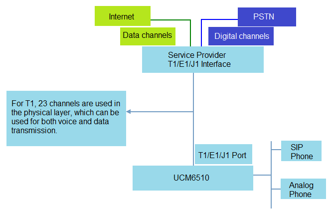
The UCM6510 supports T1/E1/J1 digital trunk and data trunk. Digital trunk allows voice transmission in digital signal while data trunk is used for data transmission so that the device can connect to the Internet. On the UCM6510, the system administrator can configure both trunks allowing voice and data transmission at the same time by specifying the channels. This document introduces how to set up T1 trunk on the UCM6510 as a configuration sample.
For more information about how to configure UCM6510, please refer to the UCM6510 user manual in www.grandstream.com/support.
Connecting T1 Port
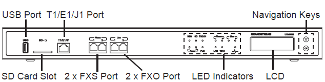
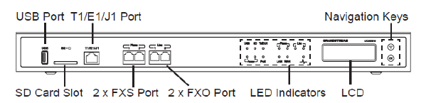
The following figure shows the UCM6510 front view where you can see the T1/E1/J1 port.
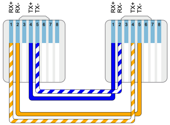
Use a T1 crossover cable to plug one end into the UCM6510 T1/E1/J1 port. Plug the other end into the T1/E1/J1 walljack. Please check if the T1 crossover cable can be provided from the service provider. The proper T1 crossover cable pin-out is shown in the following figure.
Configuring T1 Channels
-
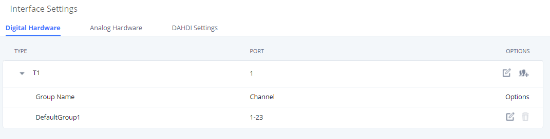
Go to UCM6510 web UI 🡪 PBX Settings 🡪 Interface Settings 🡪 Digital Hardware page. Click on
 to configure the digital hardware type.
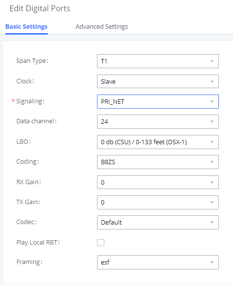
- Select Span Type “T1”. And click on “Save”.
-
Go to UCM6510 web UI 🡪PBX Settings 🡪 Interface Settings 🡪 Digital Hardware page. Click on
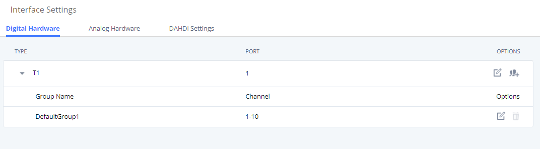
to edit the default group.
This is necessary because the default setting in default group has all the channels included. We need modify default group to make sure the number of used channels is within the max number of channels allowed for T1, E1 or J1.
For D channel, channel 16 is always used in E1 and channel 24 is always used in T1/J1.
In this example, we configured channel 1-10 in default group (for voice).
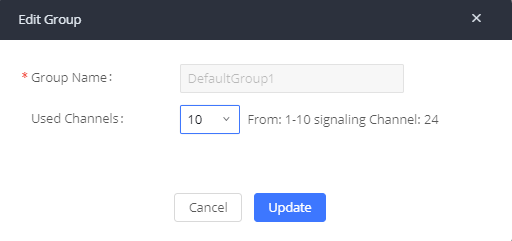
- Click on “Update” to save the setting.
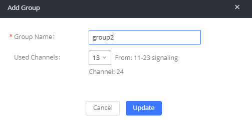
- In web UI 🡪 PBX Settings 🡪 Interface Settings 🡪 Digital Hardware page, click on

to add a new group.
As long as there are available channels, users will be able to create new group and assign channels.
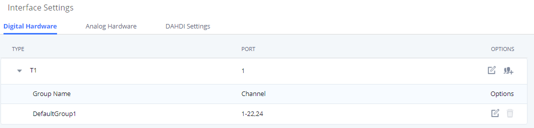
- Assign channels for the new group. In this example, we assigned channel 11 to 23 in the new group
(for data).
Configuring Digital Port
- Before configuring digital trunk, please check the physical connection of the T1/E1/J1 port as described in section [CONNECTING T1 PORT] to make sure the correct type of cable is used and properly connected.
-
Go to UCM6510 web UI 🡪PBX Settings 🡪 Interface Settings 🡪 Digital Hardware page. Click on
to configure the digital port.

- There are two tabs in the dialog to configure the digital port.

- Advanced Settings: this includes switch type and dial plan configurations.
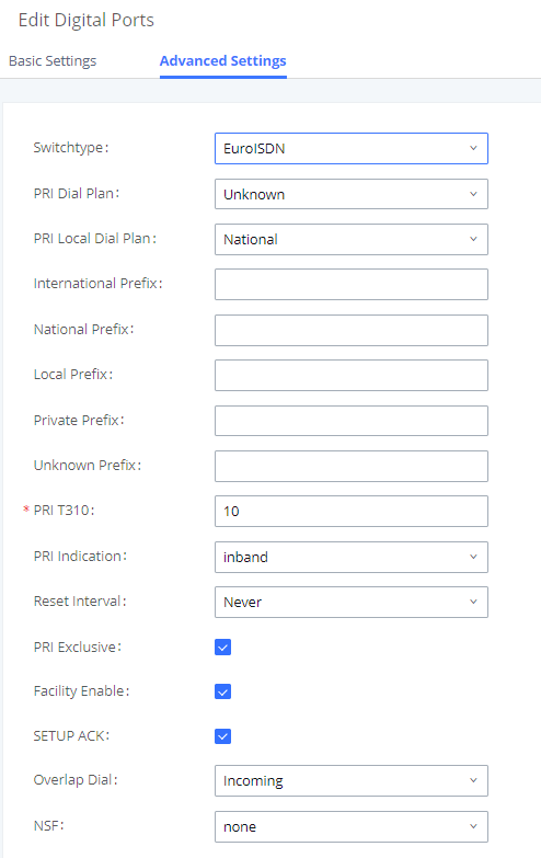
- Click on “Save” and then on apply changes.
Configuring Digital Trunk
To set up digital trunk on the UCM6510:
- Go to UCM6510 web UI 🡪 Extension / Trunk 🡪 Digital Trunks page. Click on “Add”.
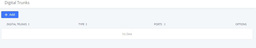
- Configure trunk name to identify this digital trunk. Select “Channel Group” to the default group for this trunk, configure CallerID, Auto Record and other options as needed.
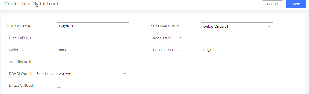
- Click on “Save” on the bottom of the dialog.
- Click on “Apply Changes” on the upper right of the web page.
- Go to web UI 🡪 System Status 🡪 Dashboard 🡪 Trunk’s page to check trunk status.
If the status shows “Available”, the digital trunk is successfully configured and should work as expected now. If it shows “Abnormal”, please check digital port configuration as described in section [CONFIGURING DIGITAL PORT] reconfigure, save and apply the changes again.
- Configure inbound routes for this digital trunk under web UI 🡪 Extension / Trunk 🡪 Inbound Routes.
- Configure outbound routes for this digital trunk under web UI 🡪 Extension/Trunk 🡪 Outbound Routes.
Until now the digital trunk has been completely configured and users should be able to make inbound and outbound calls.
Configuring Data Trunk
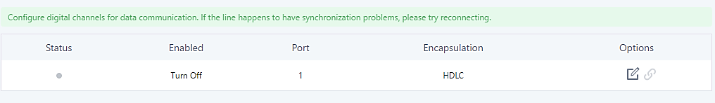
The UCM6510 E1/T1/J1 interface also supports data trunk function that allows users to access Internet. Users can select HDLC, HDLC-ETH, Cisco and PPP protocol for the data trunk.
To use data trunk,
-
Go to Web GUI🡪PBX Settings🡪Interface Settings🡪Digital Hardware page and click
 to create a new group. Designate a channel for data trunk usage in the group setting.
-
Go to Web GUI🡪Extension/Trunk🡪Data Trunks page, click on
 to edit the data trunk.
- Save the configuration and click on “Apply Changes” for the change to take effect.
-
Once connected, the data trunk will periodically ping and check the status, with status indicator shown for the data trunk on the web page. The status indicator shows
 if connected successfully.
-
If the user happens to lose connection or experience unstable connection, click on
 to reconnect to help resolve the problem.

Digital Trunk Troubleshooting
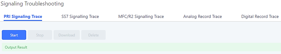
After configuring the digital trunk on the UCM6510 as described above, and it does not work as expected, users can start and download a signaling capture from the Maintenance🡪Signaling Troubleshooting page for analysis.
Depending on the signaling selected for the digital trunk, users can go to following pages to capture trace:
- PRI Signaling Trace: Web GUI🡪Maintenance🡪Signaling Troubleshooting🡪PRI Signaling Trace
- SS7 Signaling Trace: Web GUI🡪Maintenance🡪Signaling Troubleshooting🡪SS7 Signaling Trace
- MFC/R2 Signaling Trace: Web GUI🡪Maintenance🡪Signaling Troubleshooting🡪MFC/R2 Signaling Trace
- E&M Trace: Web GUI🡪Maintenance🡪Signaling Troubleshooting🡪E&M Immediate Record Trace
Here is the step to capture trace:
- Click on “Start” to start capturing trace. The output result shows “Capturing…”
- Once the test is done, click on “Stop” to stop the trace.
- Click on “Download” to download the trace.
For E&M Immediate Signaling, user could configure “Record Direction” and “Record File Mode”.
After capturing a signaling trace, users can download it for analysis. Additionally, they can contact Grandstream Technical Support from the following link for further assistance: https://www.grandstream.com/support
Using UCM6510 as E1/T1/J1 Gateway
The UCM6510 supports E1/T1/J1 which are physical connection technology used in digital network. T1 is the North American standard, J1 is used in Japan, whereas E1 is the European standard. This offers the possibility of deploying the UCM6510 as Digital Trunk with a Traditional PBX with E1, T1 or J1 interface allowing the possibility for clients behind the legacy PBX to benefit from VoIP capabilities.
This document will guide users how to configure the UCM6510 to act as Digital Gateway including inbound and outbound rules to allow routing calls from and to VoIP through the Digital Trunk.

Digital Trunk Configuration
This chapter will introduce how to connect and configure a Digital trunk between a legacy PBX with a digital card (E1, T1 or J1) and UCM6510.
We consider that UCM6510 is already peered with the VoIP Provider via SIP Trunk, for more information on how to setup a VoIP trunk please refer to the SIP Trunk Guide.
Connecting Digital Port
To connect the UCM6510 with a legacy PBX having a digital card interface, users will need first to connect each others via a crossover cable depending on the digital trunk used, users could check with their Service Provider to get the correct cable.
The following figure shows the UCM6510’s front view to locate the T1/E1/J1 port.
Configuring Digital Trunk
After connecting digital ports of the UCM6510 and PBX, users will need to configure the port type and channels, in order to create a digital trunk.
E1 Digital Trunk will be used as example to configure ports, channels and creating the Digital Trunk, and make the UCM6510 as Master while the legacy PBX will act as Slave.
Configuring Digital Channels and Ports
To configure digital channels and ports on UCM6510 please follow below steps:
- Go to UCM6510 WebUI🡪PBX Settings🡪Interface Settings🡪Digital Hardware.
- Click on under option to define the digital hardware type.
- Set Span Type to digital trunk’s type (“E1” in this example).
- Set Clock to “Master” and Signaling to “PRI_CPE” (assuming that the legacy PBX’s digital card will act as Slave). Or set Clock to “Slave” and Signaling to “PRI_NET” if legacy PBX is acting as Master.
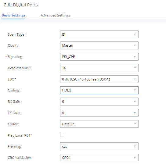
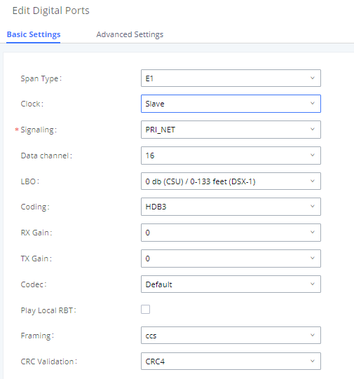
- Click on Save button to save changes.
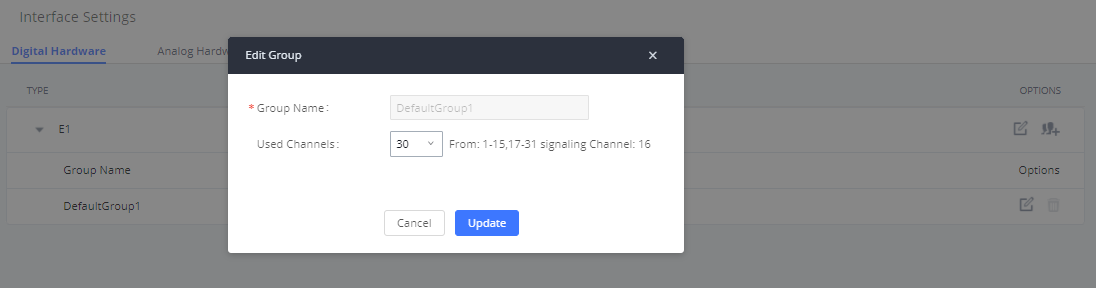
- Access to PBX🡪Ports Config🡪Digital Hardware and click on next to “DefaultGroup1” to set number of “Used Channels” on this trunk.
- Click on Update, then click on Apply Changes to save the settings.
Creating a Digital Trunk
After Configuring Ports and Channels, users can create a Digital Trunk to peer both traditional PBX and UCM6510.
To create a Digital Trunk, follow the below steps:
- Go to UCM6510 WebUI🡪Extension/Trunk🡪Digital Trunks.
- Click on “Create New Digital Trunk”.
- Set the Trunk’s Name, and select the Channel Group to be used (“DefaultGroup1” in this example).
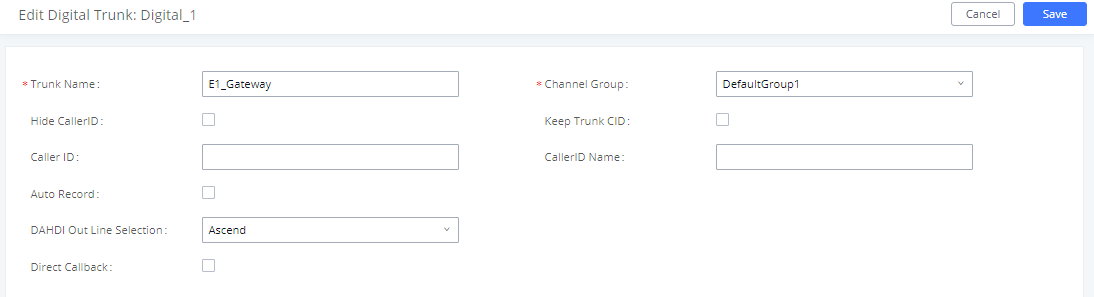
- Click on Save button then Apply Changes.
- Users can check the Trunk’s status under System Status 🡪 Dashboard 🡪 Trunks.
Outbound/Inbound Routes
Once the Digital Trunk is up and available, now we can configure the calling rules to allow users behind the legacy PBX without VoIP capability to receive/make calls through the UCM6510 acting as Digital Gateway, considering that a SIP Trunk is already set between the VoIP provider and UCM6510.
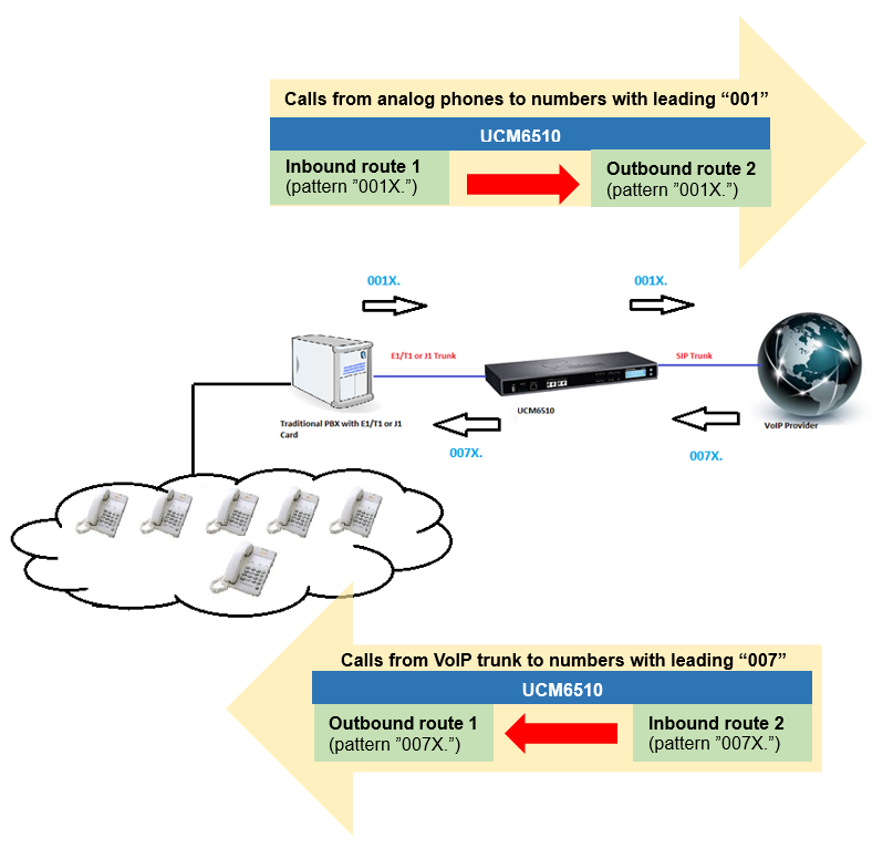
In the figure below, we will use an example where phones behind the legacy PBX will dial numbers that begins 001 which will go through the UCM6510 acting as Digital Gateway, and receive calls that begins with 007.
Users can use this example and change patterns to match their actual numbering plan.
For more details about configuring Inbound/Outbound routes, please refer to “How to Manage Inbound / Outbound Routes on UCM6XXX” guide.
Creating Outbound Route
For this scenario, we need to create 2 outbound routes on UCM6510:
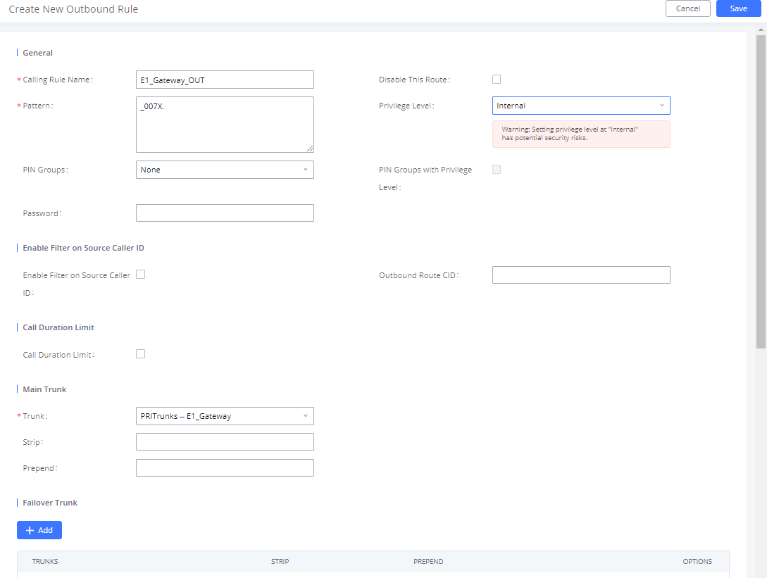
- Outbound Route 1: This route will allow outbound calls to numbers with leading 007 to go through Digital trunk (E1 trunk).
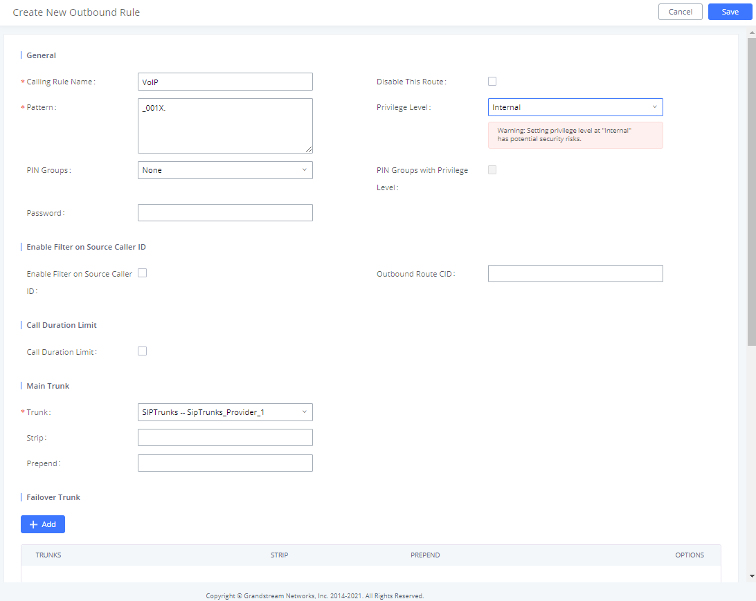
- Outbound Route 2: This route will allow outbound calls to numbers with leading 001 to go through VoIP trunk (VoIP provider).
Follow below steps to create outbound routes:
- Go to UCM6510 WebUI🡪 Extension/Trunk🡪 Outbound Routes.
- Click on “Add”.
- Set the following:
- Calling Rule Name: Name to identify this rule (example: “E1_Gateway_OUT”).
- Pattern: Matching rule to route outbound calls via the trunk (example: “_007X.”).
- Privilege level: Set privilege to allow callers with same level or higher to use this route.
- Choose the Digital Trunk set earlier, in Main Trunk field.
- Click on Save button, then Apply Changes to save the configuration.
Now that the first outbound route is created (for outbound calls through digital trunk), repeat above steps to create a new outbound route through VoIP trunk using 001X. as pattern. Refer to figure below.
Creating Inbound Route
For this scenario, we need to create 2 inbound routes on UCM6510 and should have option “Dial Trunk” enabled:
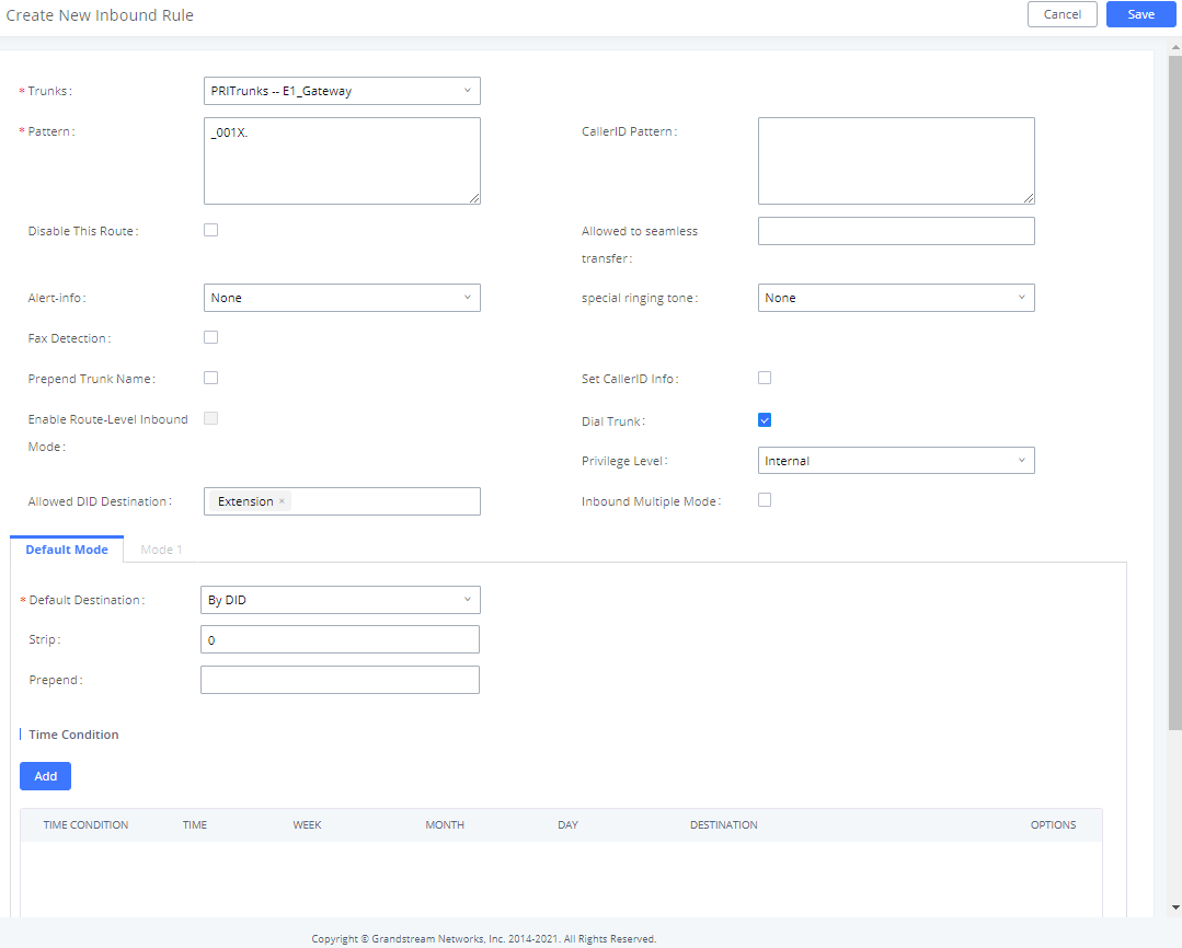
- Inbound Route 1: This route will allow incoming calls to numbers with leading 001 through Digital trunk (E1 trunk) to reach UCM6510 and be processed.
- Inbound Route 2: This route will allow incoming calls to numbers with leading 007 through VoIP trunk (VoIP provider) to reach UCM6510 and be processed.
Follow below steps to create inbound routes:
- Go to UCM6510 WebUI🡪 Extension / Trunk 🡪 Inbound Routes.
- Select the Digital Trunk from Trunks.
- Click on “Add”.
- Set the DID pattern (“_001X.” used in our calling scenario example).
- Set Destination as “ByDID”.
- Make sure to check Dial Trunk to allow users to use the VoIP trunk with provider.
- Click on Save, then Apply Changes.
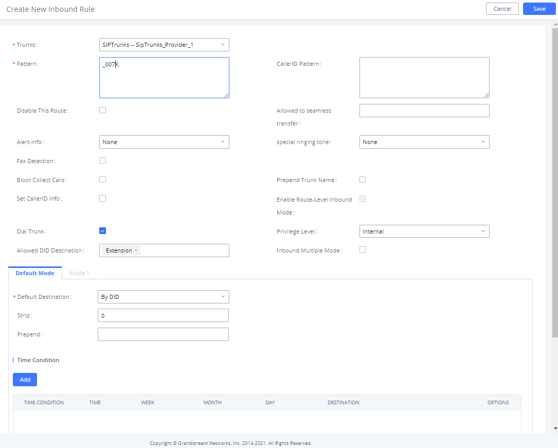
Now that the first inbound route is created (incoming calls through digital trunk), repeat above steps to create a new inbound route through VoIP trunk using “007X.” as pattern. Refer to figure below.