
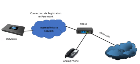
This document describes the basic configuration to interconnect the UCM6XXX series and HT813. This is typically applied to the scenario where users would like to add an HT813 not only as a remote extension but also as an external PSTN trunk. It could be common that we prefer to grab a PSTN line in a remote location and use the carrier service on another remote office, in this case, this guide will help you implement this configuration.
There are two ways to set up the UCM6XXX series IP PBX with the HT813.
- Method 1: Register the HT813 to the UCM6XXX directly.
- Method 2: Configure HT813 as a SIP peer trunk.
The following illustration shows the typical setup that will be used in this guide:
Method 1: Register HT813 to UCM6XXX
Create Extension on UCM6XXX
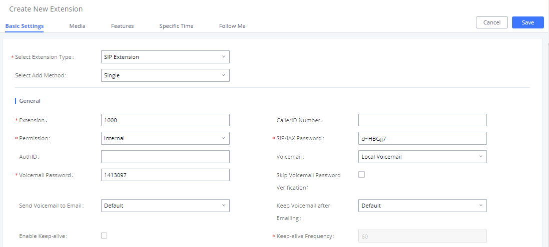
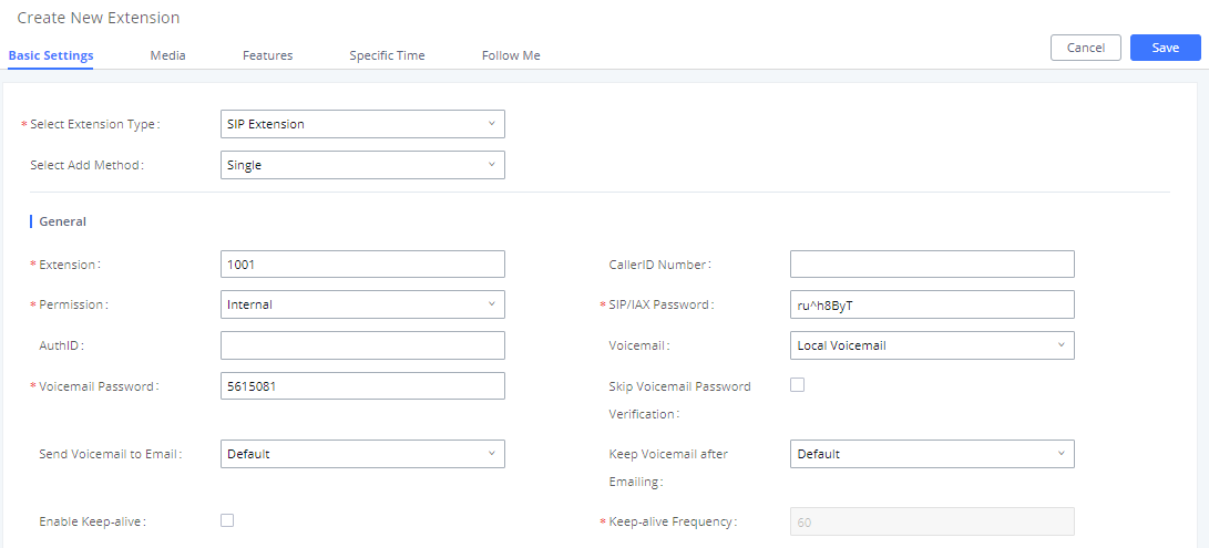
On the UCM6XXX web GUI, create two extensions under Extension/Trunk🡪Extensions. These two extensions are used for HT813 FXS and FXO registration.
The password for the extension will be randomly generated if not specified.
Create IVR on UCM6XXX
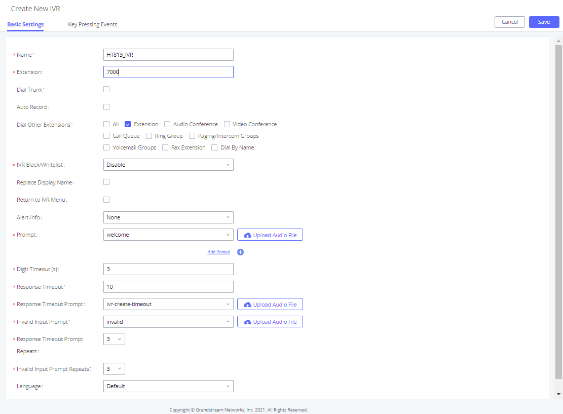
On the UCM6XXX web GUI, create an IVR extension under Call Features🡪IVR. This is to receive the calls forwarded from HT813.
In IVR settings, if “Dial Other Extensions” is enabled, the calls forwarded to the UCM6XXX IVR will be able to reach the internal extensions registered to the UCM6XXX. Also, you can assign the “Key Pressing Event” to different destinations.

Configure FXS Port on HT813
- Connect an analog phone to the HT813 FXS port.
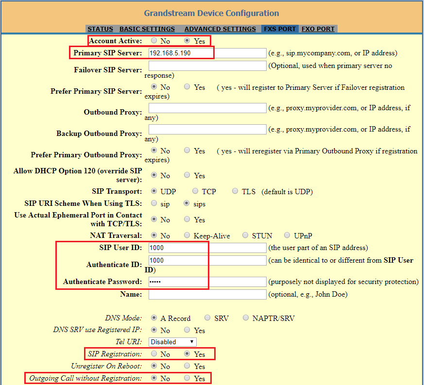
- On the HT813 web GUI, go to FXS Port setting page, configure to register the FXS port to the UCM6XXX extension 1000. Please refer to the highlighted settings in the following figure.
In this example, the UCM6XXX IP address is 192.168.5.190.
Configure FXO Port on HT813
- Connect the PSTN line to the HT813 FXO port.
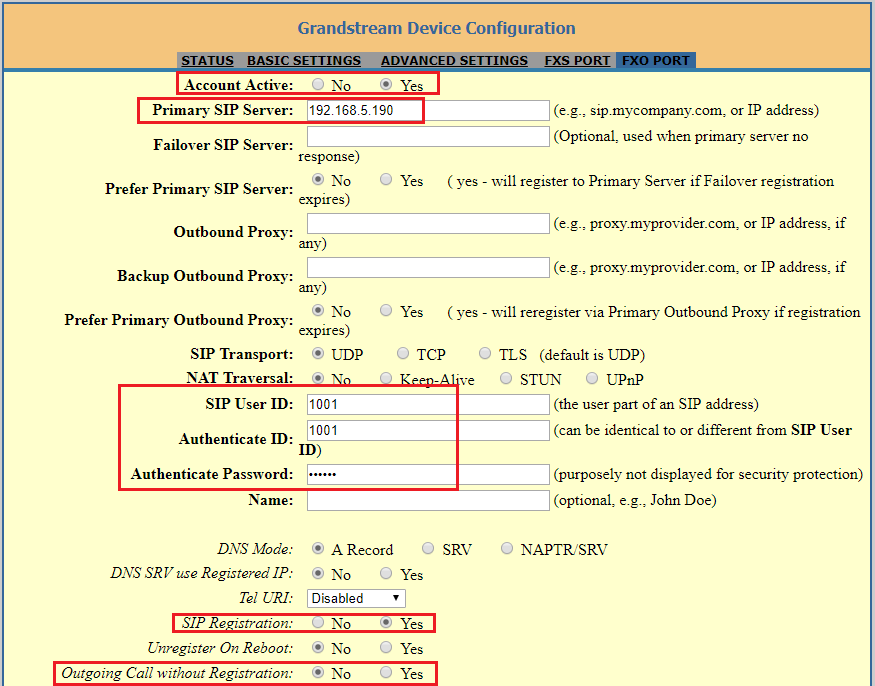
- On the HT813 web GUI, go to FXO Port setting page, configure to register the FXO port to the UCM6XXX extension 1001. Please refer to the highlighted settings and other necessary settings in the following figures.
In this example, the UCM6XXX IP address is 192.168.5.190.
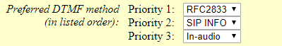
Since we are going to use IVR when the call is forwarded to the UCM6XXX, the UCM6XXX will need to be able to detect the DTMF digits. Configure the HT813 FXO port DTMF settings as below as an initial setup.
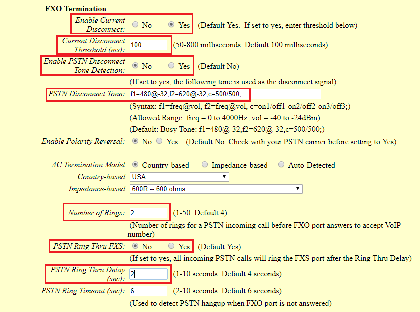
There are a few necessary changes to be made in the FXO termination section and the Channel Dialing section as well.
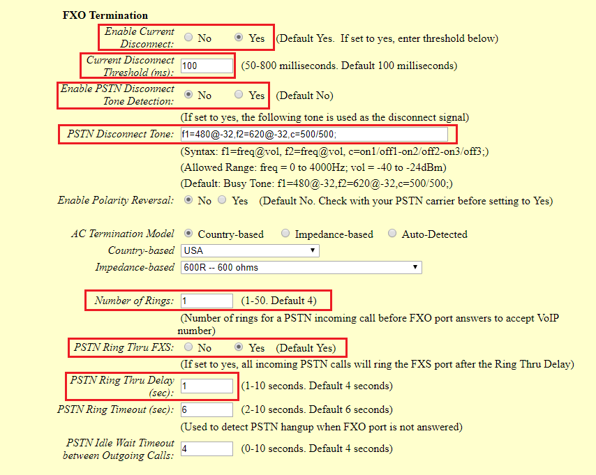
First, we should confirm which method the PSTN line is using.
If the PSTN line is using current disconnect (typical case in North America), then we should turn on “Enable Current Disconnect” and disable “Enable PSTN Disconnect Tone Detection”.
The default “Current Disconnect Threshold” is 100ms, but if you start experiencing dropped calls then you should raise this value by 100ms intervals.
If the PSTN disconnects using the tones method, then turn on “Enable PSTN Disconnect Tone Detection” and turn off the “Enable Current Disconnect” option.
For PSTN tone detection, the tone disconnect method is widely used everywhere else in the world. The North American busy tone value is “f1=480@-32,f2=620@-32,c=500/500” but these tones vary from country to country. You may look up for the settings for your country at www.3amsystems.com or download the information from http://www.itu.int/ITU-T/inr/forms/files/tones-0203.pdf.
- Set “Number of Rings” option to 1. If you happen to experience caller ID issue, you may set it to 2 or 4.
- Set “PSTN Ring Thru FXS” to “No” if you prefer not to ring the FXS port on incoming PSTN calls after the Ring Thru Delay. In the sample setup, it’s set to “Yes”.
- Set “PSTN Ring Thru Delay” option to 1. If you happen to experience caller ID issue, you may set it to 2.
- Set the “Stage Method (1/2)” to 2 for 2-stage dialing.

Configure Unconditional Call Forward on HT813
On the HT813 web GUI, go to the Basic setting page, configure “Unconditional Call Forward to VOIP” to the IVR extension on the UCM6XXX. In this example, the UCM6XXX IP address is 192.168.5.190.

How to Dial
Once the HT813 and the UCM6XXX are set up as above, the inbound call and the outbound call will be working as described below.
- Outbound call
The extension registered to the UCM6XXX can dial HT813’s FXO extension number (1001 in this example). After you get the second dial tone, you can then dial a PSTN network number. Basically, the outbound call is done in a 2-stage manner.
- Inbound call
The user from the outside network can dial into the PSTN line’s number (connected to HT813). And then he/she will reach the IVR of the UCM6XXX. The IVR on UCM6XXX would allow the user to further enter the extension number or key pressing digit to reach the desired destination.
Method 2: Connect UCM6XXX to HT813 using Peer SIP Trunk
Create IVR on UCM6XXX
On the UCM6XXX web GUI, create an IVR extension under Call Features🡪IVR.
In IVR settings, if “Dial Other Extensions” is enabled, the calls dialing into the UCM6XXX IVR will be able to reach the internal extensions registered to the UCM6XXX. Also, you can assign the “Key Pressing Event” to different destinations.
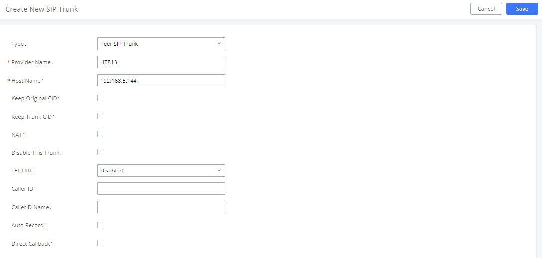
Create Peer SIP Trunk on UCM6XXX
On the UCM6XXX web GUI, create a peer SIP trunk under Extension/Trunk🡪VoIP Trunks. In this example, the HT813 IP address is 192.168.5.144.
Configure Outbound Rule on UCM6XXX
On the UCM6XXX web GUI, go to Extension/Trunk🡪Outbound Routes to create a new outbound rule. This would allow the extension on the UCM6XXX to reach numbers in PSTN network via the peer SIP trunk we just configured.
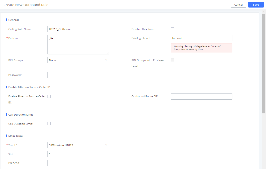
In this example “9x.”, 9 is the first dialing digit and it will be stripped off when the call goes out.
Configure Inbound Rule on UCM6XXX
On the UCM6XXX web GUI, go to Extension/Trunk🡪Inbound Routes to create a new inbound rule.
In this example, we create the DID as 20000, which will be used in the HT813 call forward setting.
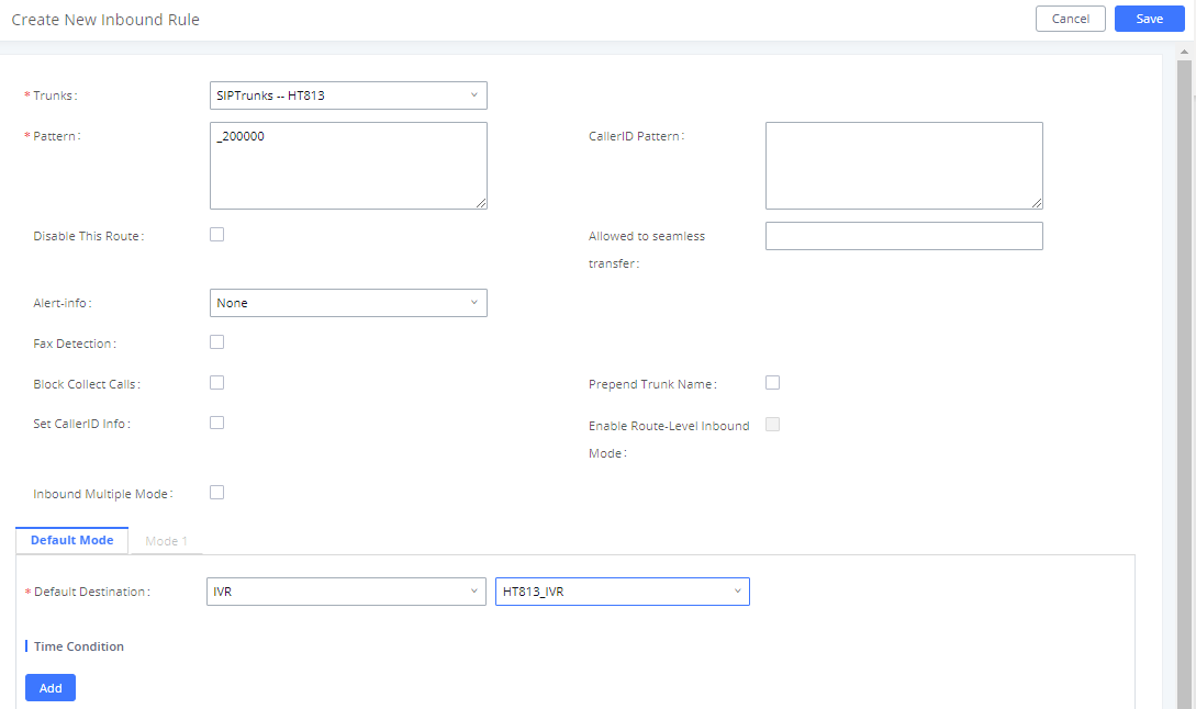
The default destination is configured to IVR.
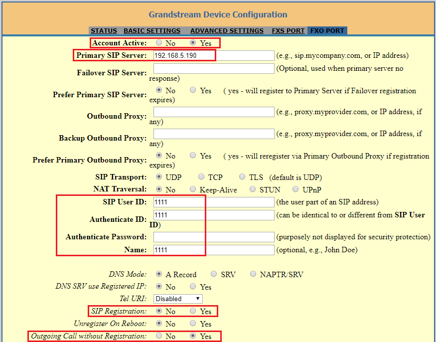
Configure FXO Port on HT813
- Connect the PSTN line to the HT813 FXO port.
- On the HT813 web GUI, go to FXO Port setting page, configure the FXO port to send signaling SIP messages to the UCM6XX’s IP address. Please refer to the highlighted settings and other necessary settings in the following figures.
You can set anything you want on the SIP user ID, authentication ID, and username. We choose 1111 in our example.
In this example, the UCM6XXX IP address is 192.168.5.190.
Since we are going to use IVR when the call is forwarded to the UCM6XXX, the UCM6XXX will need to be able to detect the DTMF digits. Configure the HT813 FXO port DTMF settings as below for an initial setup.

There are a few necessary changes to be made in the FXO termination section and Channel Dialing section.
First, we should confirm which method the PSTN line is using.
If the PSTN line is using current disconnect (typical case in North America), then we should turn on “Enable Current Disconnect” and disable “Enable PSTN Disconnect Tone Detection”.
The default “Current Disconnect Threshold” is 100ms, but if you start experiencing dropped calls then you should raise this value by 100ms intervals.
If the PSTN disconnects using the tones method, then turn on “Enable PSTN Disconnect Tone Detection” and turn off the “Enable Current Disconnect” option.
For PSTN tone detection, the tone disconnect method is widely used everywhere else in the world. The North American busy tone value is “f1=480@-32,f2=620@-32,c=500/500” but these tones vary from country to country. You may lookup for the settings for your country at www.3amsystems.com or download the information from http://www.itu.int/ITU-T/inr/forms/files/tones-0203.pdf.
- Set “Number of Rings” option to 1. If you happen to experience caller ID issue, you may set it to 2. In the sample setup, it’s set to 2.
- Set “PSTN Ring Thru FXS” to “No”.
- Set “PSTN Ring Thru Delay” option to 1. If you happen to experience caller ID issue, you may set it to 2. In the sample setup, it’s set to 2.
- Set the “Wait for Dial-Tone” to “No”.
- Set the “Stage Method (1/2)” to 1.

Exchange SIP Port Settings for FXS and FXO on HT813
- On the HT813 web GUI, go to FXO setting page, configure the “Local SIP Port” to be 5060. (The default setting is 5062.)
- On the HT813 web GUI, go to FXS setting page, configure the “Local SIP Port” to be 5062. (The default setting is 5060.)
Configure Unconditional Call Forward on HT813
On the HT813 web GUI, go to the Basic setting page, configure “Unconditional Call Forward to VOIP” to the DID number 20000. This is the same number configured in the UCM6XXX inbound route dial pattern. In this example, the UCM6XXX IP address is 192.168.5.250.

How to Dial
Once the HT813 and the UCM6XXX are set up as above, the inbound call and the outbound call will be working as described below.
- Outbound call
The extension registered to the UCM6XXX can dial prefix + PSTN number to reach outside numbers in the PSTN network, as defined in the UCM6XXX outbound route.
- Inbound call
The user from the outside network can dial into the PSTN line’s number (connected to HT813). And then he/she will reach the IVR of the UCM6XXX. The IVR on UCM6XXX would allow the user to further enter the extension number or key pressing digit to reach the desired destination. The inbound call will go through the inbound route set up on the UCM6XXX.