


The GCC6020 Series is an advanced all-in-one solution that unifies communication, networking, and security capabilities into a single, powerful platform. It integrates the functionality of four distinct systems VPN router, next-generation firewall, IPPBX, and network switch to deliver enterprise-grade performance in a compact, centrally managed appliance.
With the GCC6020 and GCC6021 models, businesses can deploy and manage wired, wireless, and VPN networks while benefiting from deep security protections such as DPI, SSL inspection, and IDS/IPS. These devices offer built-in IP PBX functionality for seamless voice and video collaboration, and support for encrypted traffic, secure boot, and high-availability deployment.
The platform supports unified management of Grandstream access points, switches, and UC endpoints through the Grandstream Device Management System (GDMS), GWN mobile app, local web UI, SSH, SNMP, and CLI making it easy to provision and maintain an integrated network.
Ideal for small-to-medium sized businesses, the GCC602x series simplifies deployment and reduces costs by consolidating business data, security, communication, and collaboration into one cohesive system.
The GCC6020 series combines the following modules:
PRODUCT OVERVIEW
Technical Specifications
The following table resume all the technical specifications including the hardware and the software specifications.
Field | GCC6020 | GCC6021 |
Network Ports | • 1× 10 Gigabit SFP+ ports • 1× 2.5 Gigabit Ethernet ports • 4× Gigabit Ethernet ports
| • 4× 10 Gigabit SFP+ ports • 8× 2.5 Gigabit Ethernet ports • 16× Gigabit Ethernet ports
|
Auxiliary Ports | • 1× CONSOLE • 1× USB 3.0 | • 1× CONSOLE • 1× USB 3.0 • 2× HA • 1× MGMT |
Memory | 4GB RAM, 32GB eMMC | 4GB DDR4+256MB DDR3 RAM, 32GB eMMC, 128MB NAND |
External Storage | M.2 SSD (Optional) | |
Routing | 6.5Gbps | 10Gbps |
IPSec VPN Throughput | 1.3Gbps | |
NAT Sessions | 320K | |
Supported number of VLAN | 256 | |
NGFW Throughput (DPI+IPS) | 6Gbps | 9Gbps |
Total No-Blocking | 13Gbps | 76Gbps |
Note: Values shown apply when Hardware Acceleration is enabled. | ||
Switching Capacity | 26Gbps | 152Gbps |
Note: Values shown apply when Hardware Acceleration is enabled. | ||
PBX | 50 users and 16 concurrent calls by default Upgrades available for purchase: (See more for PBX capacity upgrade options) | |
Mounting | Desktop, Wall, and Rack-mountable | Desktop and Rack-mountable |
Material | Metal | |
LEDs | 1× LED for SFP+, 5× LED(G/Y) for Ethernet Ports, 5× LED(Y) for PoE Out, 1× LED(R/G/B) for device tracking and status indication, 1× LED for main power, 1× LED for Redundant Power System | 24× LED(G/Y) for Ethernet Ports/PoE Out, 4× LED for SFP+, 2× LED for HA, 1× LED(R/G/B) for device tracking and status indication, 1× LED for main power, 1× LED for Redundant Power System |
Connection Type | DHCP, Static IP, PPPoE | |
Network Protocols | IPv4, IPv6, IEEE802.1q, IEEE 802.1p, IEEE802.1x, IEEE802.3, IEEE 802.3u, IEEE802.3ab | |
QoS | • VLAN, TOS • Support multiple traffic classes, filter by port, IP address, DSCP, and policing • App QoS: Application/protocol monitoring and traffic statistics • VoIP Prioritization | |
Firewall | • DDNS, Port Forwarding, DMZ, UPnP, DoS & Spoofing defense, traffic rules, NAT • DPI, Anti-Virus, IPS/IDS, SSL Proxy • Content Control: DNS filtering, web url/class/key words filtering, application identification and control • Email Security, Geo-IP filtering | |
VPN |
| |
Network Management | Grandstream Device Management System (GDMS), GWN App, Local Web GUI, SSH, SNMP (v1/v2c/v3) and CLI | |
Max AP/Clients | Up to 300 GWN APs; Up to 500 Clients | Up to 300 GWN APs; Up to 1000 Clients |
Power and Green Energy Efficiency | Universal power adaptor included: Input 100-240VAC 50-60Hz Output: 54VDC/2.8A (150W); 5× PoE out ports support IEEE802.3af/at, Maximum PoE Wattage: 120W RPS Input: 54VDC/2.8A | Universal power adaptor included: Input 100-240VAC 50-60Hz Output: 54VDC/7.8A (420W); 8× PoE out ports support IEEE802.3 af/at/bt, 16× PoE out ports support IEEE 802.3 af/at, Maximum PoE Wattage: 370W RPS Input: 54VDC/7.8A |
Environmental | Operation: 0°C to 45°C Storage: -10°C to 60°C Humidity: 5% to 95% Non-condensing | |
Physical | Unit Dimension: 280 x 185.5 x 44 mm Unit Weight: 1.5KG Entire Package Dimension: 384 x 209.5 x 60 mm Entire Package Weight: 2.1KG | Unit Dimension: 440 x 301.5 x 44mm Unit Weight: 4.2KG Entire Package Dimension: 557 x 413 x 138mm Entire Package Weight: 5.6KG |
Package Content | GCC6020/GCC6021, Universal Power Supply, Rack mount kit, Quick Installation Guide | |
Compliance | FCC, CE, RCM, IC | |
GCC6020 technical specifications
INSTALLATION
Before deploying and configuring the GCC6020 device, the device needs to be properly powered up and connected to the network. This section describes detailed information on the installation, connection, and warranty policy of the GCC6020 device.
Package Contents
The GCC6020/GCC6021 package includes the following components:

Label | Quantity | Item |
a | 1× | Main Unit (GCC6020 or GCC6021) |
b | 1× | Power Cable |
c | 1× | Grounding Cable |
d | 2× | Rack Mount Brackets (model-specific) |
e | 8× | Rack Mounting Screws |
f | 1× | Power Cord Anti-Trip |
g | 4× | Rubber Feet |
h | 1× | Regulatory Information |
i | 1× | Quick Installation Guide |
j | 2× | M.2 SSD Screws (top) |
k | 1× | M.2 SSD Securing Screw (bottom) |
Package Contents
Hardware Overview
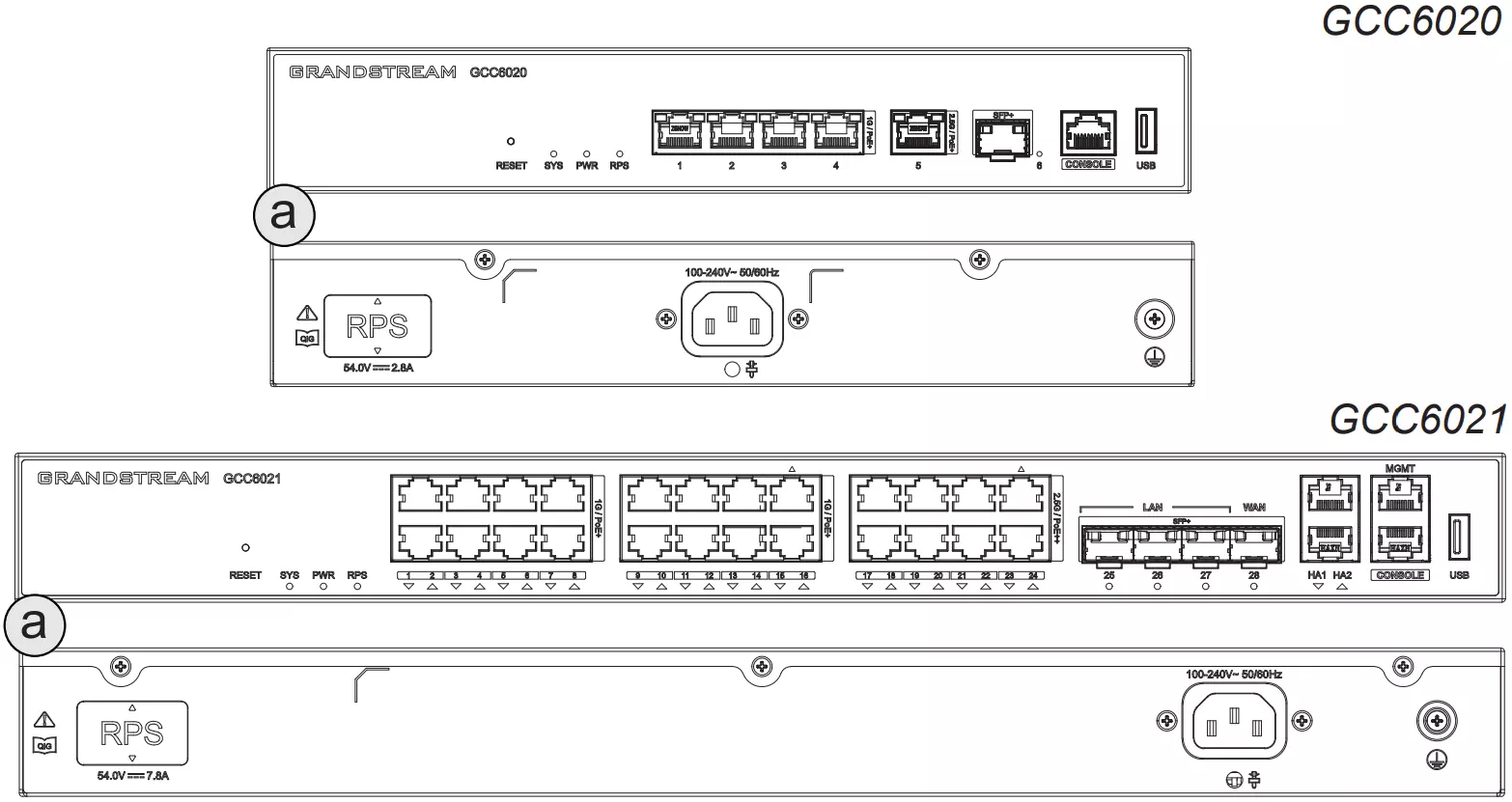
The GCC6020 and GCC6021 feature front and rear panels with multiple Ethernet, SFP, USB, and management ports. The exact port layout varies depending on the model.
Each unit includes a standard AC power input and a Redundant Power Supply (RPS) port on the back panel. LED indicators on the front help monitor power, connectivity, and system status.
Powering the Device
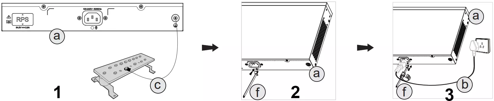
Follow the steps below to properly power the GCC6020/GCC6021:
- Ground the Device
Attach the grounding cable (c) to the grounding point (a) on the rear panel to prevent electrical surges. - Secure the Power Cable
Install the power cord Anti-Trip (f) onto the power socket. This helps prevent accidental unplugging or cable strain. - Connect the Power Cable
Plug the power cable (b) into the device, then wrap the Power Cord Anti-Trip (f) around it as shown before connecting to a power outlet.
LED Indicators
LED lights | Indication | LED Status | Remarks |
LAN/WAN LED | LAN/WAN port connection | Solid Green | |
LAN/WAN port data exchange | Flashing green | The flashing frequency is related to the network transmission rate. The faster the rate, the faster the flashing frequency. | |
PoE Out power supply | Solid Orange | Models supporting PoE Out | |
No connection | Off | ||
System LED | Shutdown | Off | |
Normal operation | Solid Blue | ||
Firmware Upgrade | Flashing Green -> Solid Green -> Solid Blue | ||
Upgrade failed | Solid Red | ||
Factory Reset | Red flashes 6 times -> off ->Pink light on for about 3 seconds -> Solid Green -> Solid Pink | ||
AP pairing process | Flashing Blue -> Solid Blue | AP System LED Status | |
Modify the configuration | Flashing Blue -> Solid Blue | AP System LED Status, If the configuration changes are minor and the update is fast, the indicator light may remain blue. | |
Delete pairing | Red flashes 6 times -> off -> Solid Green -> Solid Pink | AP System LED Status | |
Mesh | Flashing Yellow -> Solid Blue | AP System LED Status | |
PWR/RPS power LED | Power supply not in use/failed | Off | |
Power supply in use | Solid Green | ||
HA (High Availability) | Connected | Solid Green | |
Not connected | Off |
Rack Mount Installation
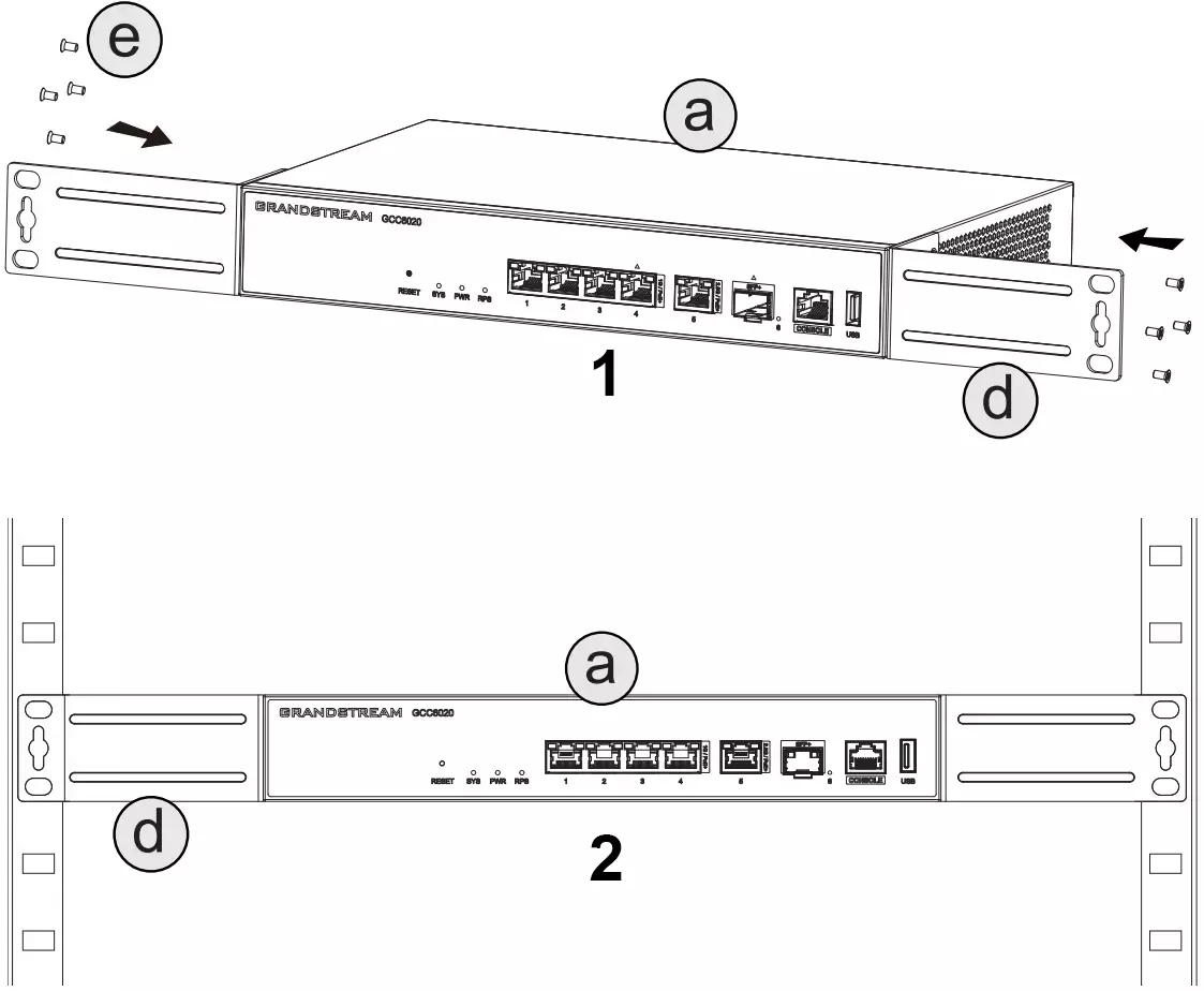
To mount the device into a standard 19” rack:
- Attach the Rack Brackets
Secure the provided rack mount brackets (d) to both sides of the device (a) using the included screws (e). - Install the Unit into the Rack
Carefully align and slide the device into the rack, then secure the brackets to the rack frame.
Installing the M.2 SSD
- Access the SSD Slot: Flip the device upside down to locate the SSD compartment (a). Remove the bottom SSD cover by unscrewing the pre-installed screw.
- Install the SSD: Secure the standoff screw (k) in the appropriate mounting position. Insert the M.2 SSD module into the slot at an angle, then press it down flat. Fasten it using the hold-down screw (j) to secure the SSD in place.
- Close the SSD Compartment: Reattach the metal cover and tighten the original screw to finish the installation.

Connecting to GCC602x
- Connect the WAN port (marked with △) to your internet uplink such as an optical modem, router, or ISP-provided gateway.
- Connect a PC or laptop to one of the LAN ports on the GCC602x.
- Open a web browser and access the default gateway:
http://192.168.80.1orgcc.grandstream.com
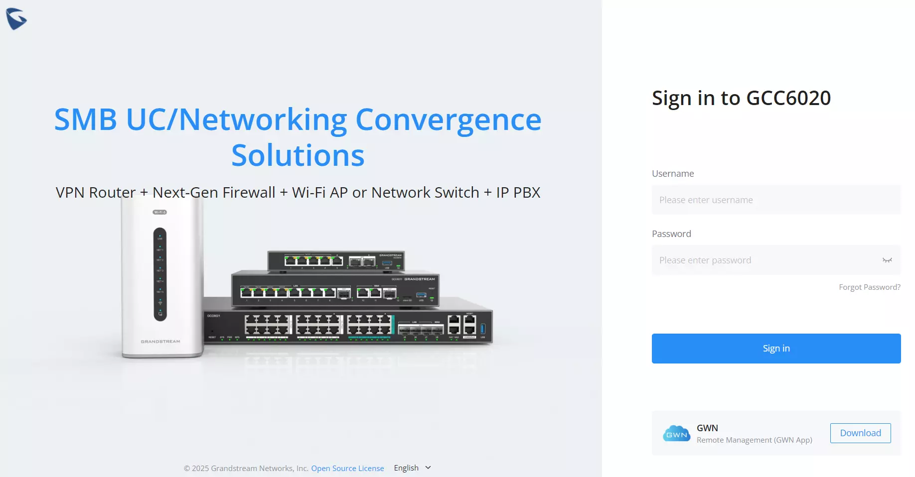
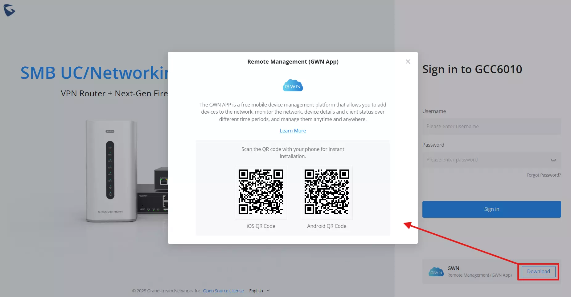
When powering on the GCC602x device for the first time (or after a factory reset), users will be prompted with the login screen shown below.
GWN Remote Management App
On the login screen, users will also find an option to download the GWN App for remote management.
Click the Download button under “GWN Remote Management” to view platform-specific QR codes:
- Scan the QR code with your phone to install the app:
- Left: iOS (App Store)
- Right: Android (Google Play)
For more details, check GWN App for Android – User Manual or GWN App for iOS – User Manual.
Safety and Precautions
Getting Started
Setup Wizard
When powering on a brand-new GCC60xx device or after a factory reset, the system will launch the Initial Setup Wizard automatically. Follow the steps below to complete the basic configuration.
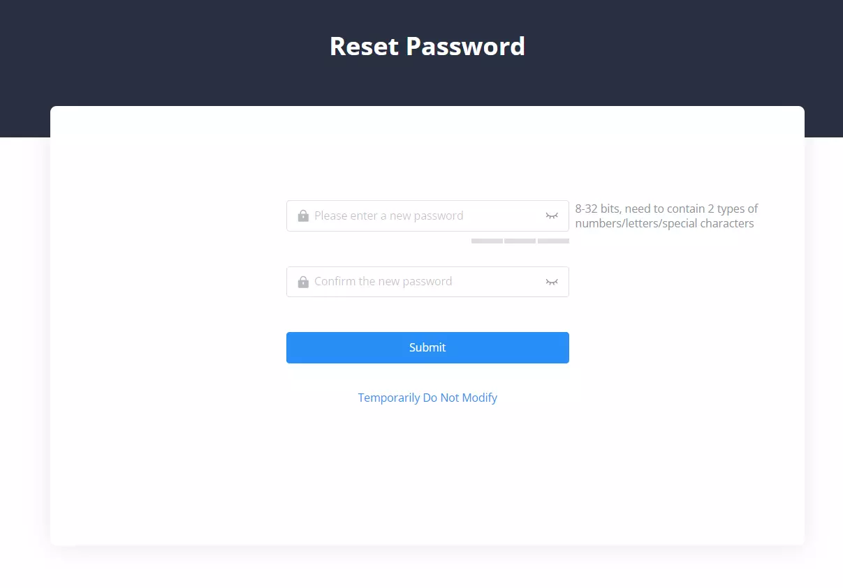
Step 1: Change Password
After logging in for the first time, you’ll be prompted to reset the default password. Enter your new password twice and click Submit.
Make sure your password is 8–32 characters long and includes at least two of the following: letters, numbers, and special characters.
Alternatively, you may click Temporarily Do Not Modify to skip password reset, but this is not recommended for security reasons.
Step 2: Welcome Screen – Launch Setup Wizard
Once the new password is set, the system will log you out. Log in again with your updated credentials.
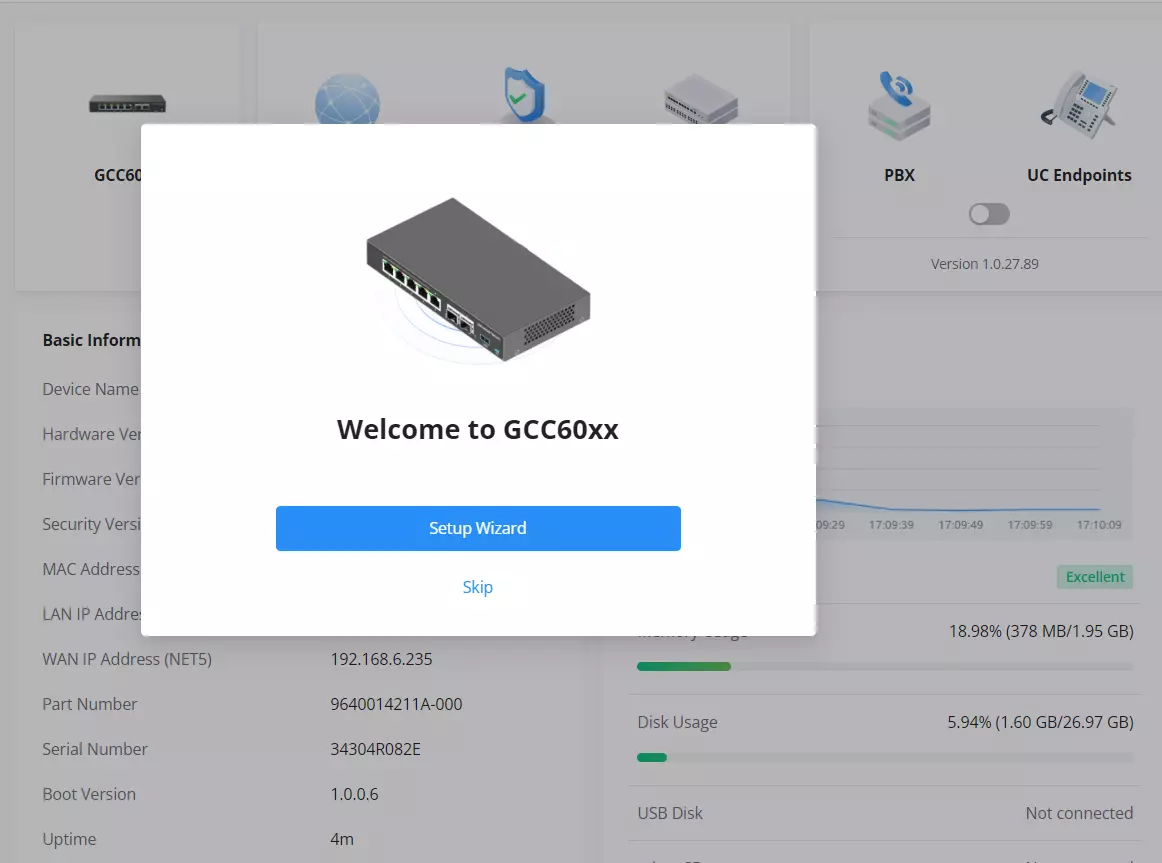
After successful login, the system displays a welcome prompt with two options:
- Setup Wizard: Starts the initial configuration process.
- Skip: Takes you directly to the dashboard (not recommended unless setup was previously completed).
Step 3: User Settings
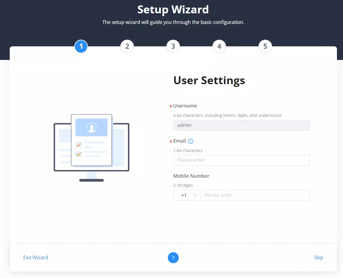
After clicking Setup Wizard, the configuration will begin with the User Settings page.
Fill in the following fields:
- Username: Between 4–64 characters (letters, digits, or underscores).
- Email: (Optional) Used for alerts and recovery.
- Mobile Number: (Optional) For two-factor notifications or alerts.
Use the blue arrow at the bottom to continue to the next step.
You may also choose to Exit Wizard or Skip this step entirely.
Step 4: Email Sending Settings – Part 1
This step configures how the device sends system emails.
- TLS: Toggle ON for secure transmission.
- Type: Select
Clients(recommended) orMTA. - Email Format: Choose
HTMLorPlain Text. - SMTP Server: Enter your outgoing mail server address (IPv4 or hostname).
- SASL Authentication: Toggle ON to enter credentials.
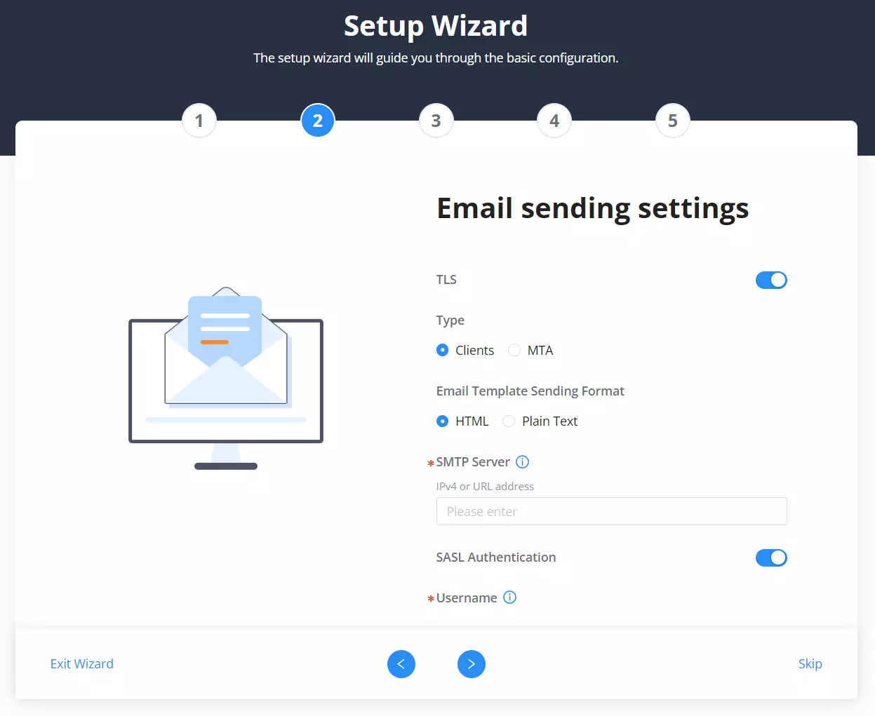
Step 5: Email Sending Settings – Part 2
Continue email configuration by entering:
- Username: Your email address.
- Password: Email server password.
- Display Name: This name will appear in outgoing emails.
- Sender Email: The sender address for system messages.
- Click Test to confirm email functionality.
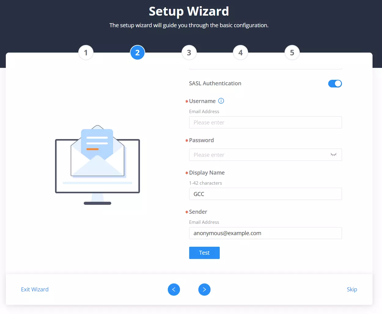
Step 6: Basic Settings
Define your basic device identity here:
- Device Name: A unique name for this GCC6020 unit.
- Country / Region: Select your location.
- Time Zone: Choose the relevant time zone.
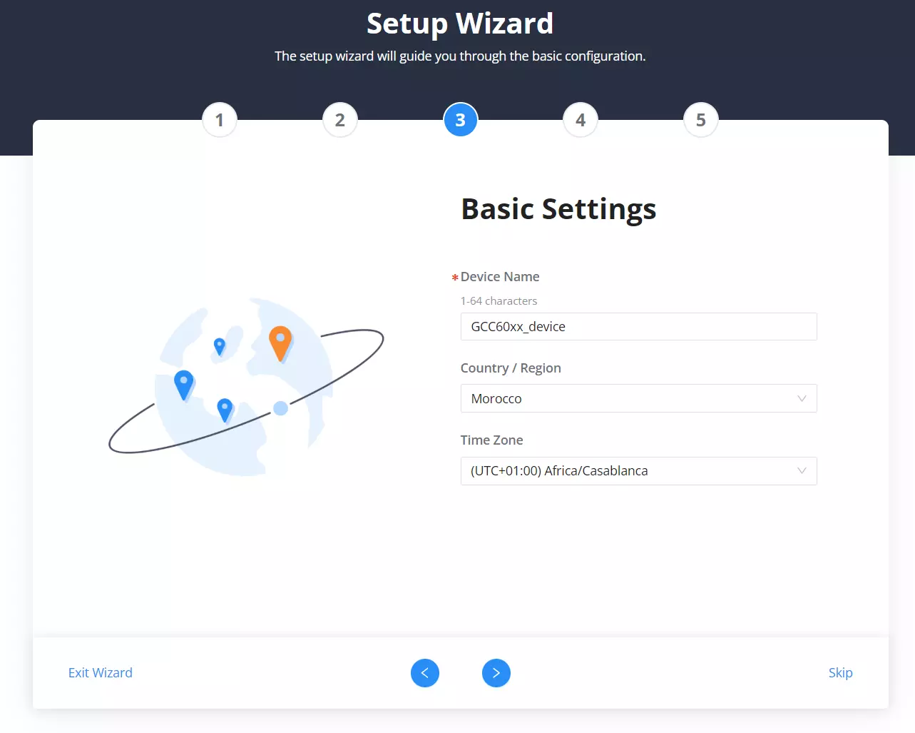
Step 7: Internet Settings
Configure how the device connects to the internet.
- WAN Name: Label your WAN interface.
- Port Speed: Choose between Auto Negotiation, 10/100/1000 Mbps, etc.
- Connection Type: Select from
DHCP,Static, orPPPoE. - DNS Servers: Enter preferred and alternate DNS servers if necessary.
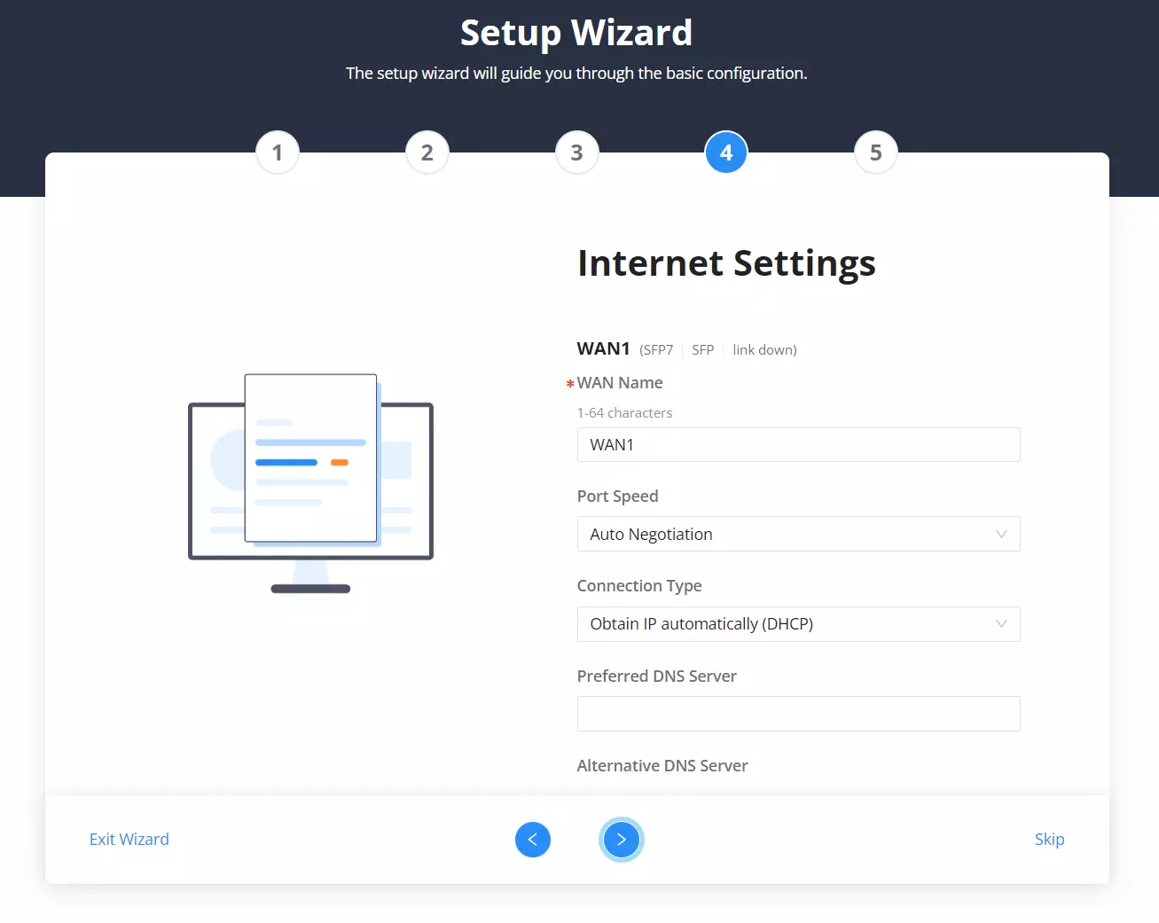
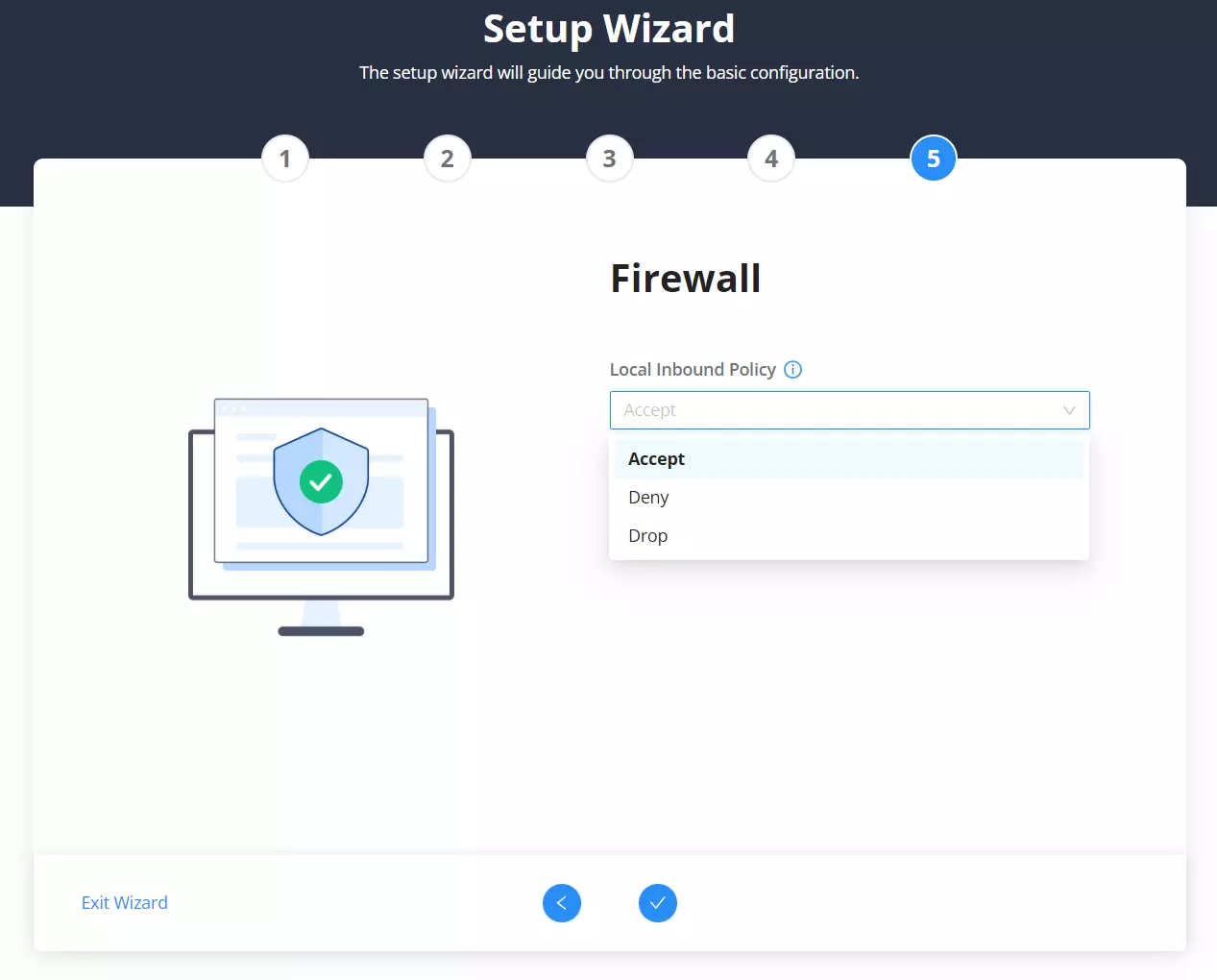
Step 8: Firewall Policy
Set the Local Inbound Policy to control how traffic is handled.
Options:
- Accept: Allow incoming traffic.
- Deny: Block traffic but respond with rejection.
- Drop: Block silently without response.
Step 9: Setup Complete
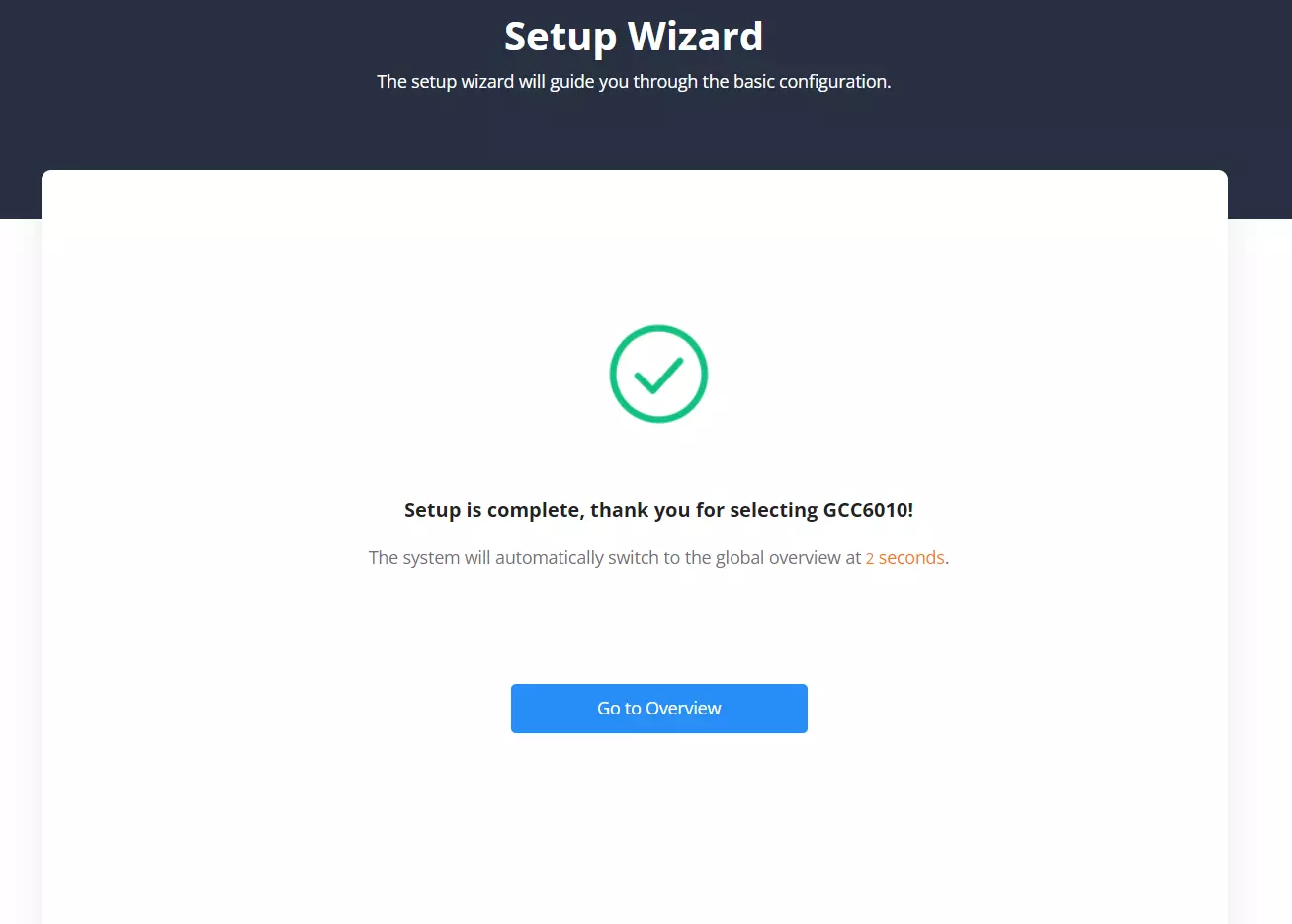
Once all steps are completed, a confirmation screen appears.
Click Go to Overview to enter the main dashboard and begin using the device.
The system will automatically redirect in a few seconds if no action is taken.
Interface Language
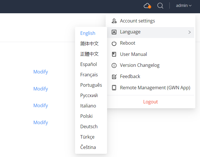
After logging in for the first time, users can change the Web UI language based on preference.
To do so:
- Click on your username in the top-right corner (default:
admin) - From the dropdown menu, navigate to Language
- Select your preferred language from the list
Note: The interface will reload automatically in the selected language.
Feedback
Users can submit feedback directly from the top navigation bar by clicking the username in the upper right corner and selecting Feedback from the dropdown menu.
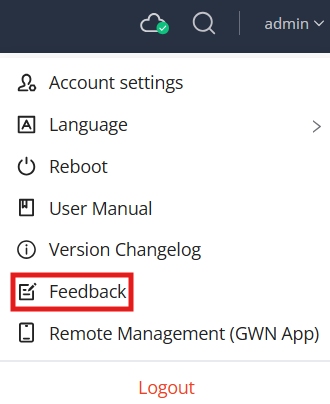
The feedback system provides four categories to choose from:
- I have an issue/bug to report and need a solution
- I need help on my configurations
- I have feedback
- Others
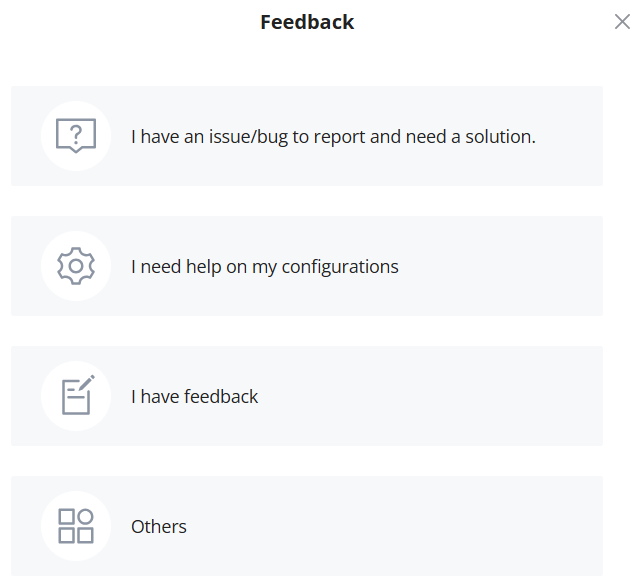
The first two categories will redirect the user to the official help desk support page.
The last two options will open a feedback submission form, allowing users to:
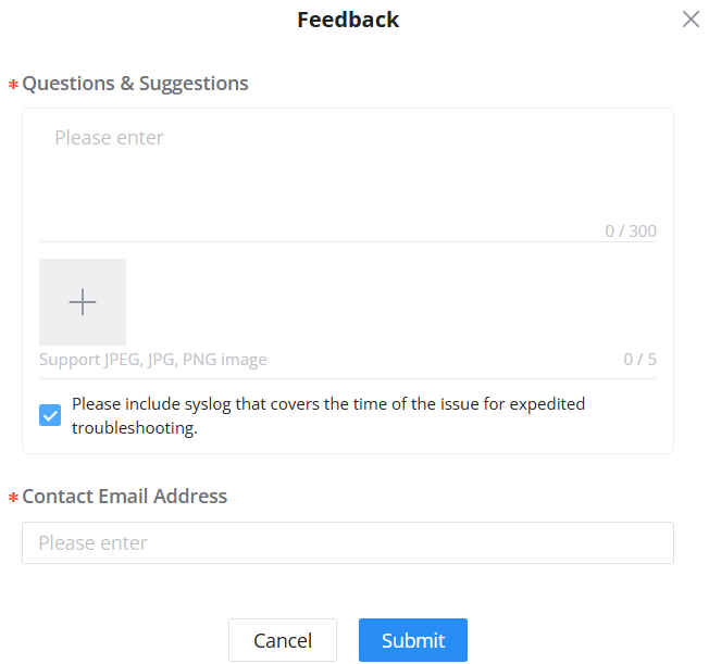
- Write a message (up to 300 characters)
- Upload up to 5 images (JPEG, JPG, PNG formats)
- Enter a contact email address
- Optionally include a syslog file to assist with issue diagnosis and troubleshooting
This categorized interface improves the user experience by streamlining support and suggestion handling within the Web UI.
Remote Management (GWN App)
The Remote Management (GWN App) option is available from the user menu in the top-right corner of the interface.
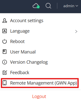
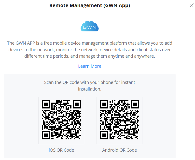
Clicking this option opens a QR code panel for downloading the GWN mobile app on iOS or Android.
The GWN App allows users to:
- Remotely manage devices
- Monitor network and device performance
- View client connection history
- Access the network anytime from a mobile device
HOME
Overview
The Overview section provides a snapshot of the device’s current operational status and system modules. This includes detailed info such as hardware/software versions, system resource usage, licensing, and session statistics.
Device Modules & Version Panel
The top panel displays the five system modules supported by the GCC6000 series device:
- Networking
- Firewall
- Network Nodes
- PBX
- UC Endpoints
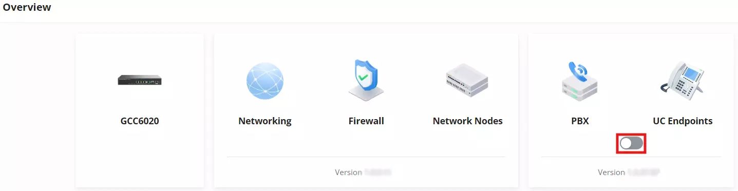
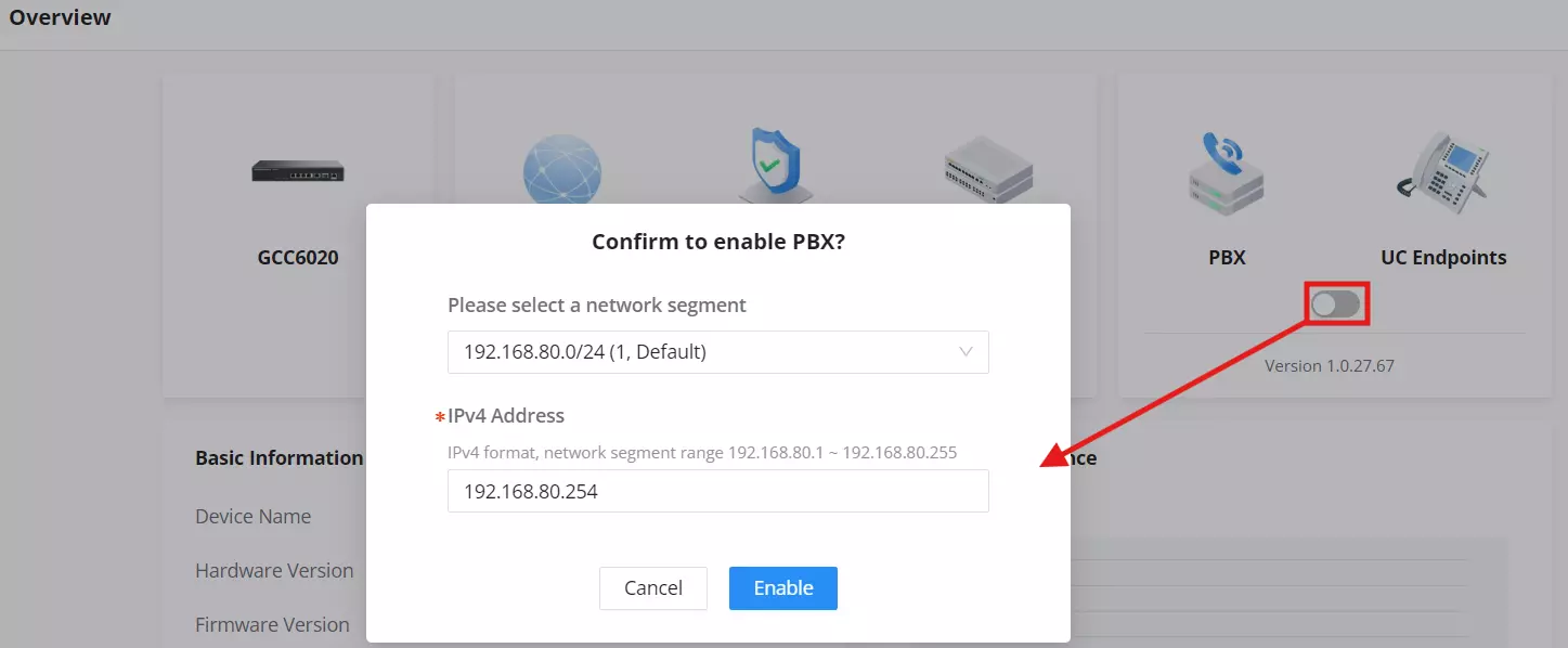
PBX and UC Endpoints can be toggled ON/OFF depending on deployment needs. Disabling these modules may help conserve resources for networking functions.
When enabling PBX, users are prompted to assign a VLAN segment and specify an IPv4 address from the selected range.
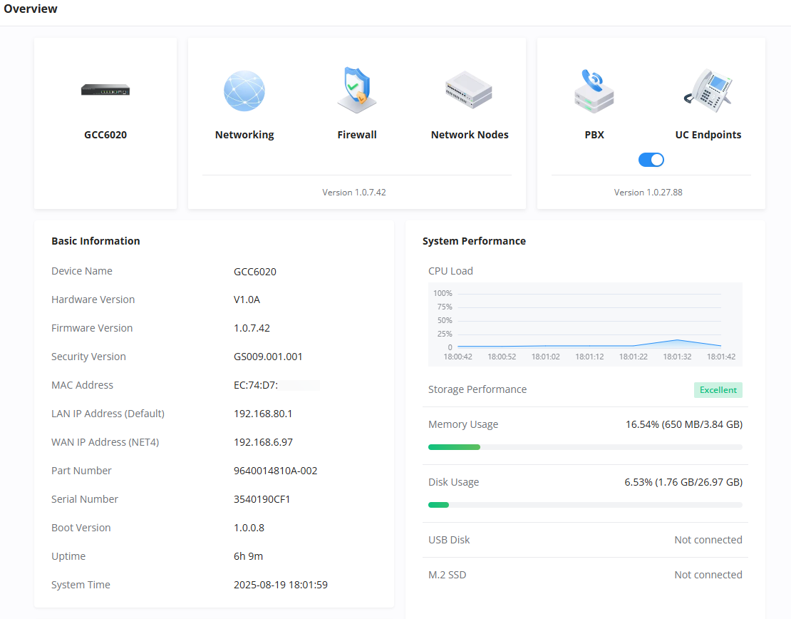
Device Info & System Performance
This middle panel displays essential system details:
Basic Information
- Device name, MAC, LAN/WAN IP, Part Number, Serial Number
- Uptime and current system time
System Performance
- CPU load graph
- Memory & disk usage
- USB and SD card status
Firewall Service
- Shows current license type and status
PBX
- Displays the current PBX IP address (if enabled)
Real-Time Session Statistics
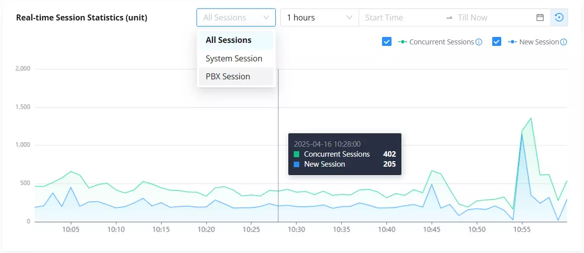
The final section shows a dynamic graph of active sessions in real time.
💡 Features:
- Filter by All Sessions, System Session, or PBX Session
- Choose custom time duration (e.g. 1 hour, 12 hours, etc.)
- View session count by type:
- Concurrent Sessions
- New Sessions
- Hover to reveal stats for any specific timestamp
- Use the ⟳ icon to reset the data
Topology
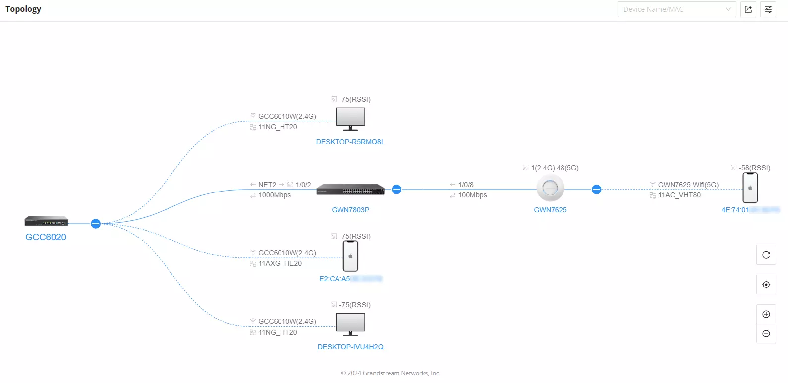
In this section, the administrator can view the topology of the Grandstream networking device connected to the GCC device.
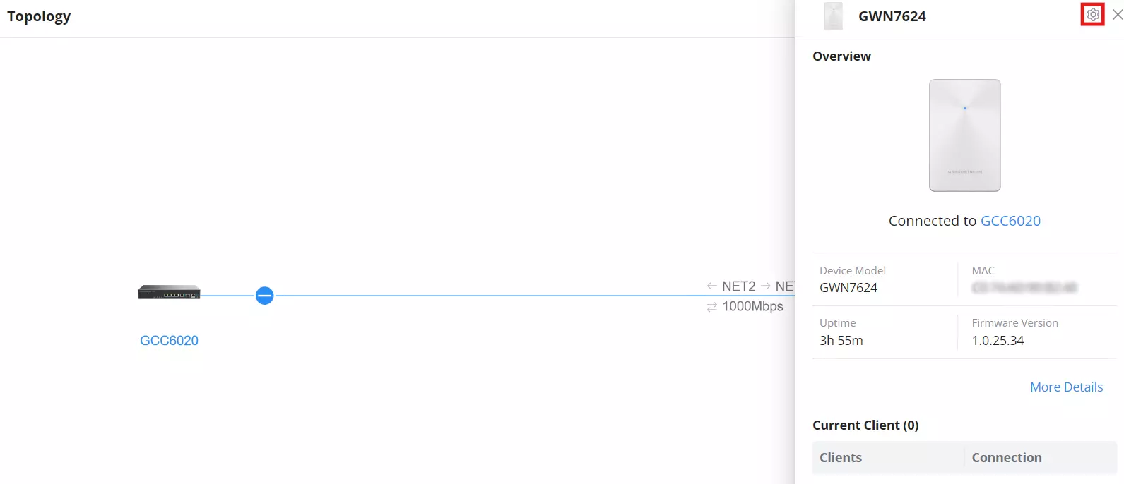
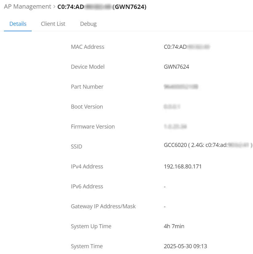
When clicking on the highlighted icon below, the user can view the device details and settings
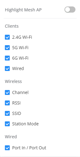
To filter the types of devices that are shown on the topology click on 
System Settings
In this section, the user can configure settings related to the general operations of the device.
Basic Settings
Basic Settings
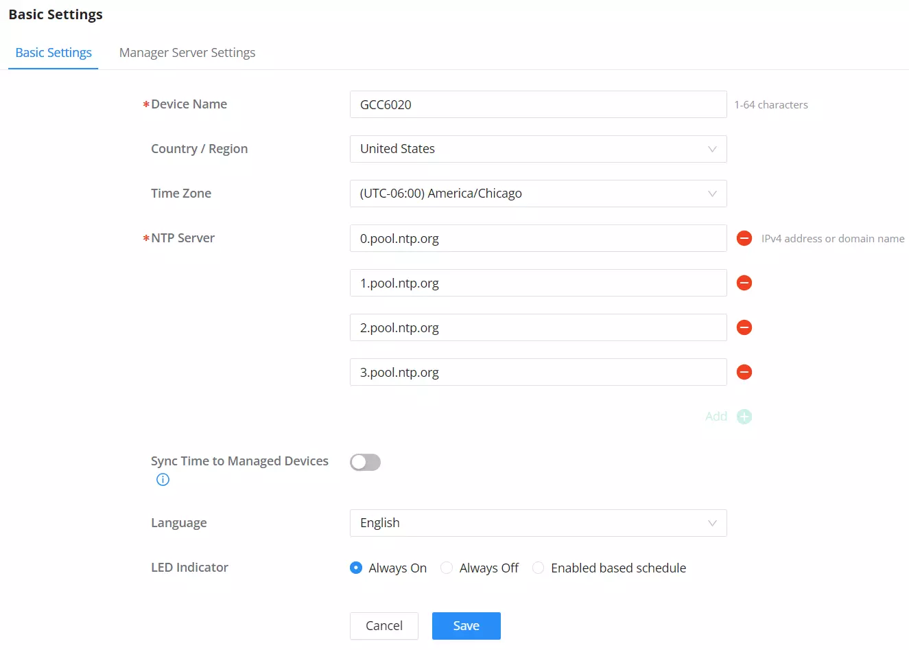
To configure the device’s general parameters such as name, time zone, NTP server, and language:
- Navigate to System Settings → Basic Settings.
- Adjust the fields as needed.
- Click Save to apply your changes.
For more details, refer to the figure and table below.
Field | Description |
Device Name | Sets a unique name to identify the device. Supports 1–64 characters. |
Country / Region | Selects the country for localization settings (e.g., default time zones, UI language). |
Time Zone | Defines the system time zone. Some locations (e.g., Asuncion, Almaty) use fixed UTC offsets and do not follow DST changes. |
NTP Server | Primary server used to synchronize the system time. Enter a domain or IP address. |
“+” Add NTP Server | Click the “+” icon to add additional NTP servers for redundancy — if one fails, others will be used as backup. |
“-“Remove NTP Server | Click the “-“ icon next to an entry to remove it. |
Sync Time to Managed Devices | When enabled, the GCC device will push its NTP-configured time to all managed devices (like APs or switches) for unified time sync. |
Language | Sets the web interface display language. |
LED Indicator | Sets the device’s LED behavior. Options include Always On, Always Off, or Enabled based on schedule. |
Basic Settings
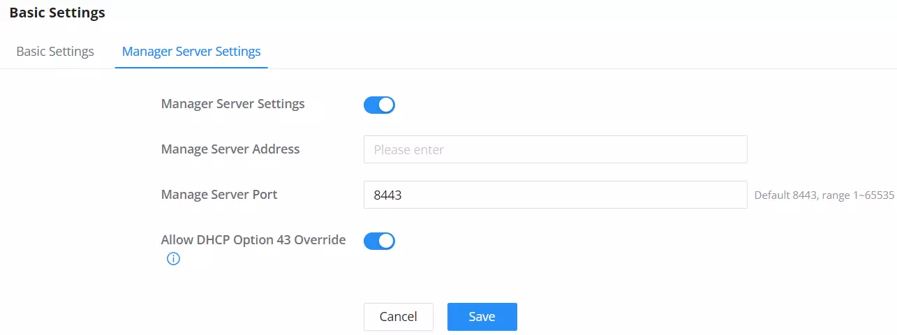
Manager Server Settings
Security Settings
In this section, the user will be able to configure different security-related settings. These settings are mainly related to securing user access to the device either locally or remotely.
Account Settings
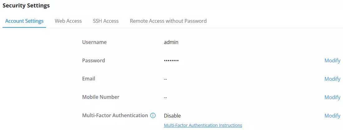
This section allows administrators to manage essential login and security details for the web portal access of the GCC device.
Users can modify credentials, enable Multi-Factor Authentication (MFA) for enhanced login security, and configure notification details.
For more details, refer to the figure and table below.
Field | Description |
Username | Displays the default login username (not editable). |
Password | Allows updating the administrator login password. |
Optional field for system alerts and notifications. | |
Mobile Number | Optional contact number, used for notifications (where supported). |
Multi-Factor Authentication | Enables additional login verification using an MFA code. If enabled, users will enter a time-based one-time password (TOTP) after the main login credentials. A setup guide is available through the link shown. |
Modify (links) | Use the “Modify” button next to each field to update its value. |
Account Settings
Web Access
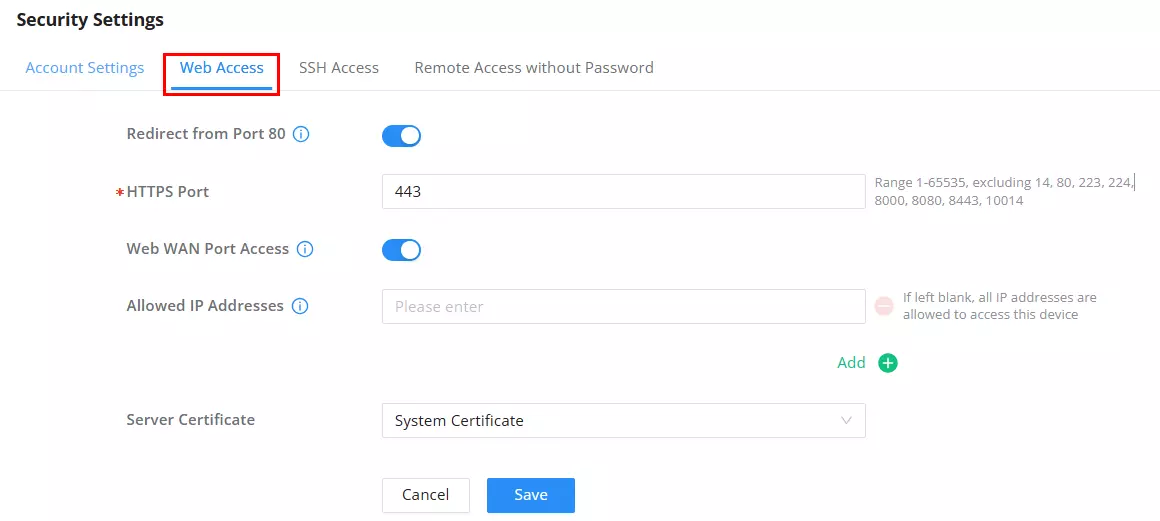
The Web Access tab allows administrators to configure how the GCC6020 device is accessed through the web interface, including WAN accessibility, HTTPS port, IP restrictions, and server certificate settings. This helps strengthen remote management security and limit exposure.
For more details, refer to the figure and table below.
Field | Description |
Redirect from Port 80 | Enable or disable redirection from HTTP (port 80) to HTTPS. Disabling this will stop automatic redirect to secure access. |
HTTPS Port | Port used for HTTPS web access. Range: 1–65535 (excluding: 14, 80, 223, 224, 8000, 8080, 8443, 10014). |
Web WAN Port Access | Allows or restricts web access over the WAN interface. |
Allowed IP Addresses | Specify IP addresses allowed to access the web interface via WAN. If left blank, all IP addresses are permitted. |
Server Certificate | Select the server certificate used for HTTPS access. This certificate is mandatory to be able to acces the GCC web GUI using HTTPS. If no valid certificate is configured, then the system will use HTTP instead. |
Web Access
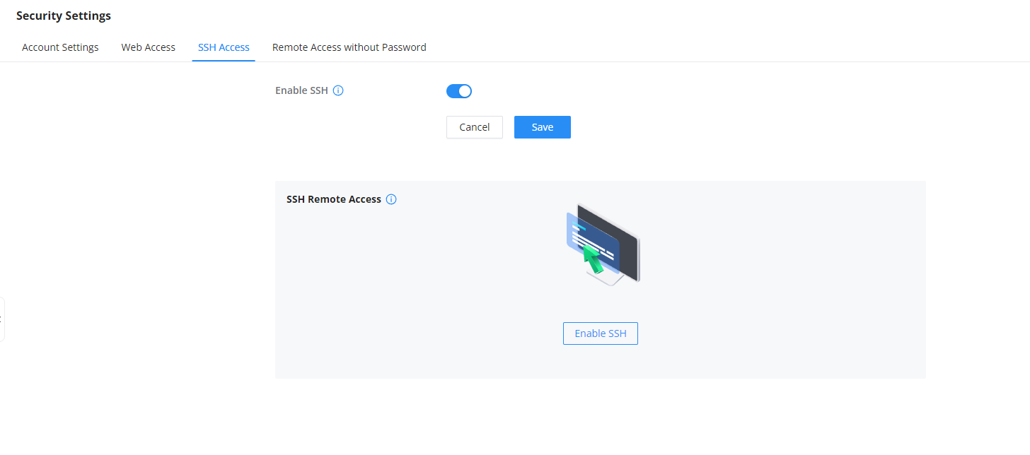
SSH Access
In this section, the user can enable SSH remote access to the device, this includes SSH remote access as well.
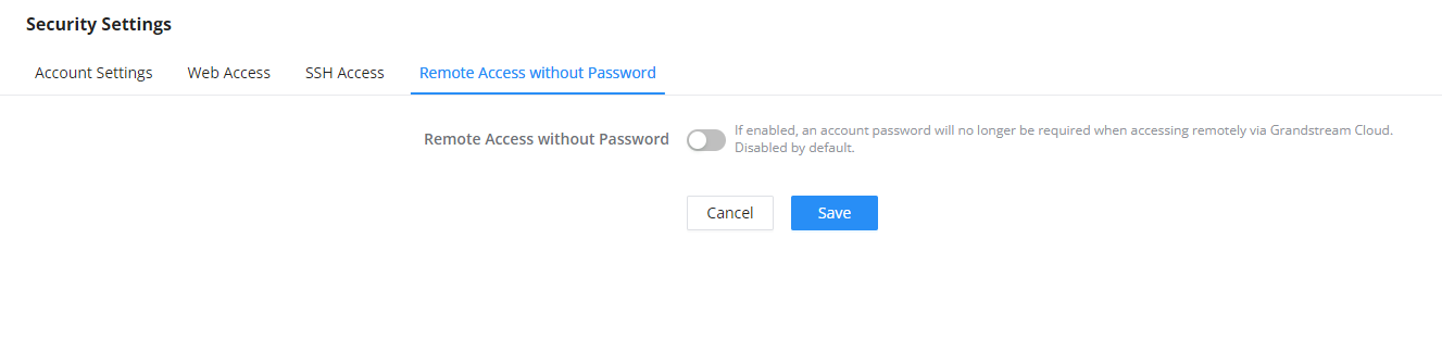
Remote Access without Password
Enabling passwordless remote access allows you to access the device through the GDMS management platform without having to provide a username and password for authentication.
Schedule
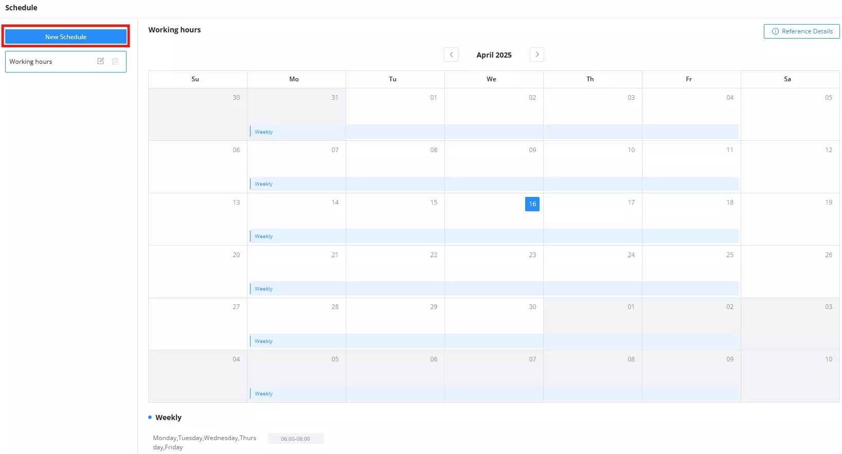
The Schedule section allows users to create time-based rules that can be applied across various features such as SSID broadcasting, firewall rules, system backups, and more. These schedules help control when specific services or actions should be active.
To configure device schedules, navigate to: System Settings → Schedule
Click New Schedule to begin creating a custom schedule.
When creating a schedule, you can choose between two types:
- Weekly (repeating): Recurs weekly on selected days and times.
- Absolute (non-repeating): Defines one-time actions for specific dates and time slots.
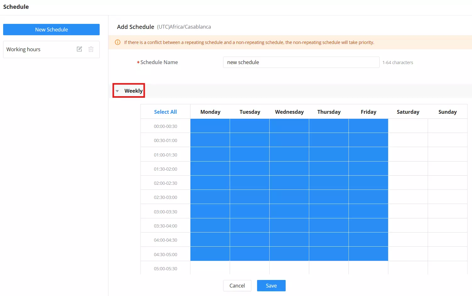
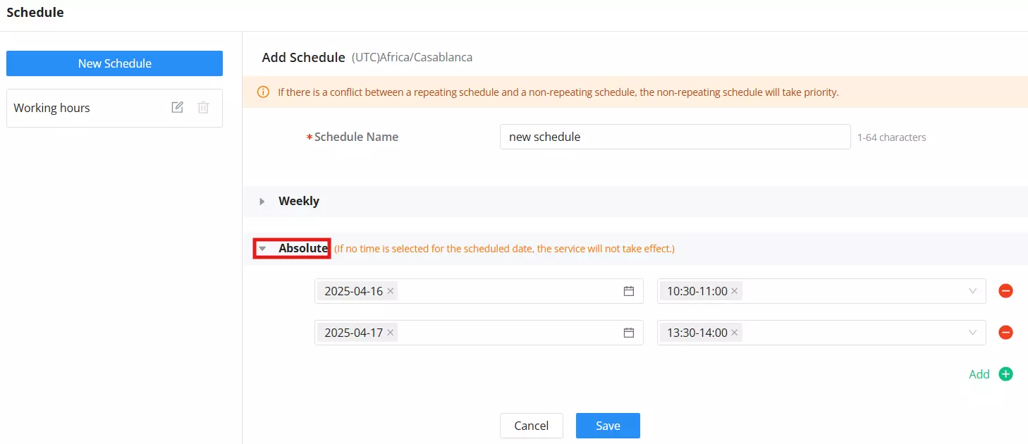
Users can add time slots per day and save the configuration to make the schedule available for assignment.
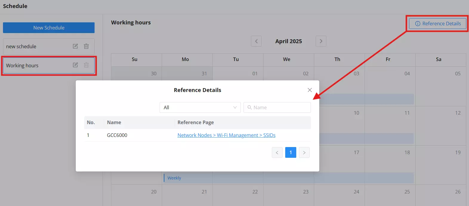
Once created, schedules can be applied in various modules. To check where a schedule is currently in use, click Reference Details.
The Reference Details window shows a list of all modules referencing the selected schedule. This helps prevent accidental deletion of schedules that are actively in use elsewhere.
Administrator
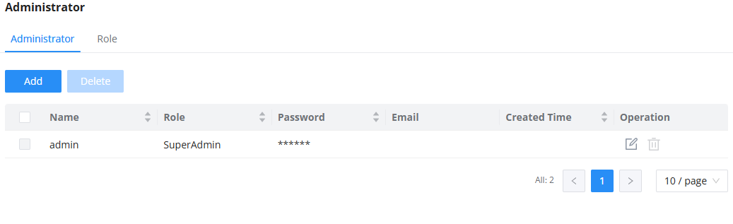
In this page, the administrator can create users with various roles and privileges.
Administrator
In this section, the user can create new users by clicking on the  button.
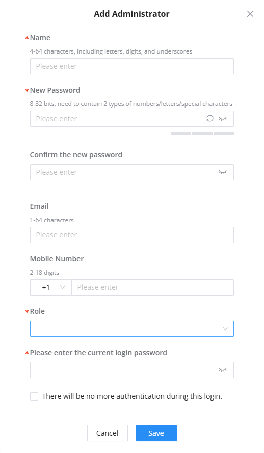
Name | Enter the username. The username can consist of 4-64 characters, including letters, digits, and underscores. |
New Password | Enter the password. The password can consist of 8-32 characters, need to contain 2 types of numbers/letters/special characters |
Confirm the new password | Enter the password again to confirm it. |
Enter the email of the user. The email entered should be limited between 1-64 characters | |
Mobile Number | Enter the mobile number of the user. The phone number is limited between 2-18 digits |
Role | Select the role of this user. The role must be created first, before it’s assigned to the user under |
Please enter the current login password | Since only the super administrator is allowed to create other administrators, the super administrator needs to enter their password as a measure of security when creating a new administrator. Enable the option “There will be no more authentication during this login” to disable this measure of security during the configuration session. |
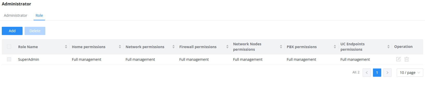
Role
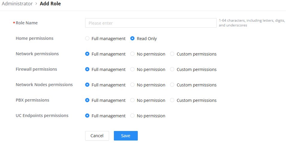
In this section, the user can create roles that can be assigned to different users. By default, the SuperAdmin role is pre-created and assigned to the default administrator account of the device. To create more roles, click on the button.
Email Settings
The Email Settings section allows the GCC6020 device to send notification emails for various system events. When properly configured, the device can deliver emails to specified recipients in response to triggers such as alerts, scheduled meetings, emergency events, and more.
Email notifications can include the following types of information:
- Extension information
- Remote registration of an extension
- Wave welcome message
- Missed call notifications
- Scheduled multimedia meetings
- Scheduled meeting reports
- Alert events
- Emergency calls
- Password reset emails
Email Setting
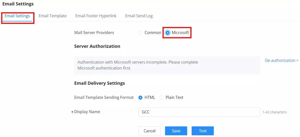
The configuration interface includes a Mail Server Providers option, which defines how email delivery is handled:
- Common: Traditional SMTP-based delivery. This mode allows administrators to manually configure all required email settings including SMTP server, authentication, TLS, and sender details.
- Microsoft: A streamlined option for Microsoft® 365 and Outlook integration. SMTP settings are hidden, and the system requires Microsoft account authorization instead. Only essential delivery fields such as display name and template format are shown.
The interface updates dynamically based on the selected provider to simplify configuration and match the requirements of the chosen email service.
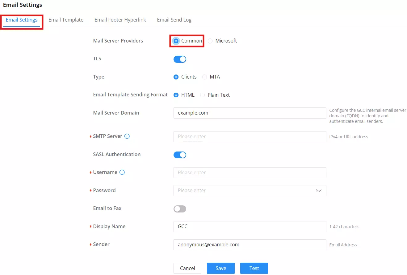
Mail Server Providers | Select the type of email service provider:
|
When Mail Server Providers set to Common | |
TLS | Enable or disable TLS during transferring/submitting your Email to another SMTP server. The default setting is “Yes”. |
Type | Select Email Type:
|
Email Template Sending Format |
|
Mail Server Domain | Specify the domain name to be used in the Email when using type “MTA”. |
SMTP Server | Enter the address of the SMTP server when using type “Client”. The address can be either an IP address or a FQDN. |
SASL Authentication | Enable Simple Authentication and Security Layer. When this option is disabled, the device will not try to use the username and password for mail client authentication. Most of the mail servers require authentication while some other private mail servers allow anonymous login, which requires disabling this option to send email as normal. For Microsoft Exchange Server, please disable this option. Note: This option is available when Type is “Clients”. |
Username | Enter the username created for the SMTP client. Note: This option is available when Type is “Clients”. |
Password | Enter the username created for the SMTP client. Note: This option is available when Type is “Clients”. |
Email To Fax | Monitors the inbox of the configured email address for the specified subject. If enabled, the IPPBX will get a copy of the attachment from the email and send it to the XXX extension by fax. The attachment must be in PDF/TIF/TIFF format. Note: This option is available when Type is “Clients”. |
Email-to-Fax Blocklist/Allowlist | The user can enable the Email-to-Fax Blacklist or Email-to-Fax Whitelist. |
Email-to-Fax Subject Format | Select the email subject format to use for emails to fax.
XXX refers to the extension that the fax will be sent to. This extension can only contain numbers. Note: This option is available when Type is “Clients” and “Email to Fax” is enabled. |
Fax Sending Success/Failure Confirmation | Email address blacklist/whitelist for local extensions. Note: This option is available when Type is “Clients” and “Email to Fax” is enabled. |
POP/POP3 Server Address/Port | Configure the POP/POP3 server address and port for the configured username Note: This option is available when Type is “Clients” and “Email to Fax” is enabled. |
Display Name | Specify the display name in the FROM header in the Email. |
Sender | Specify the sender’s Email address. For example: pbx@example.mycompany.com. |
When Mail Server Providers set to Microsoft | |
Server Authorization | Displays the Microsoft authorization status. To enable email sending via Microsoft® services, users must complete the authentication process. A de-authorization option is available to revoke access. |
Email Template Sending Format | Choose whether the email should be sent in HTML or Plain Text format. |
Display Name | Specify the display name that will appear in the “From” field of outgoing emails. Maximum 42 characters. |
Email Template
The user can customize the layout of the emails sent by the device to the various users. The device already provides a pre-configured layout that can be modified.
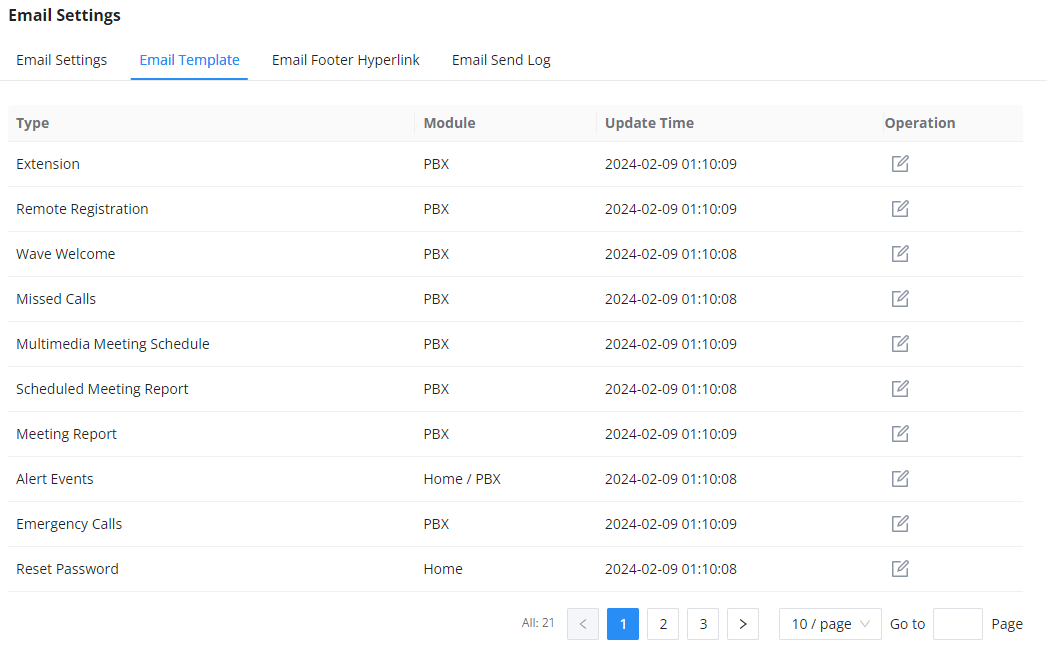
The user can click on the edit button  to edit a specific template.
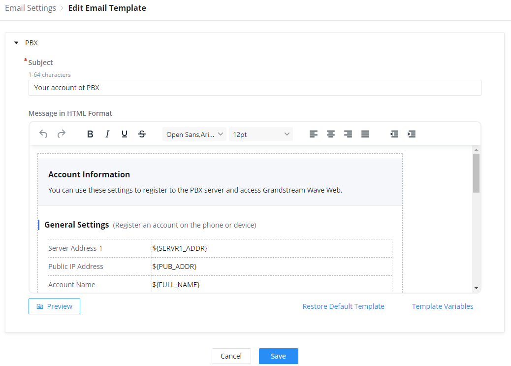
The user can use the text editor to change the layout. Once that is done, the user can view the new layout by clicking on  .
.
Email Footer Hyperlink
The customize the links that are included in the footers, please navigate to System Settings → Email Settings → Email Footer Hyperlink
On the page, you can edit the text and the URL of each footer. You can add 3 additional footers if needed.
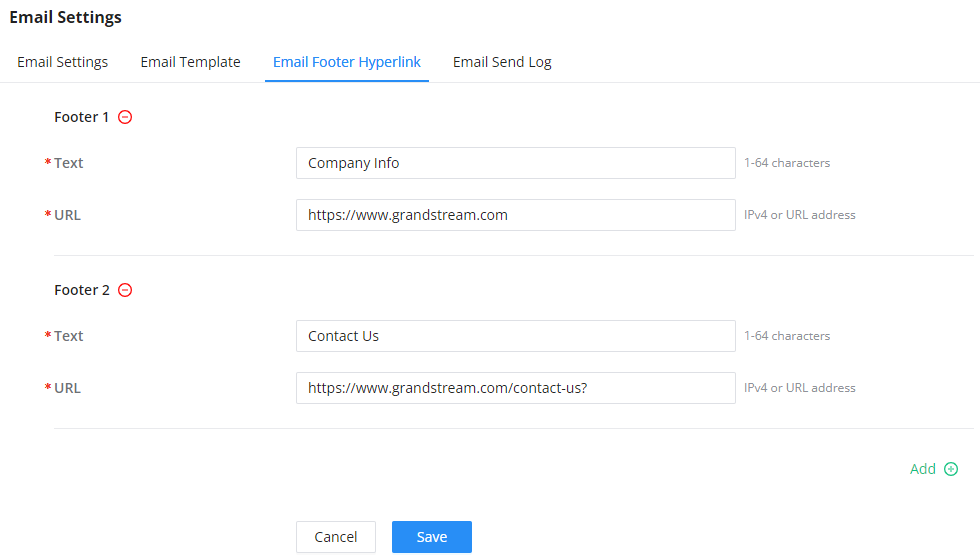
Email Send Log
Email send log is used to keep records of all the emails that have been sent from the GCC device.
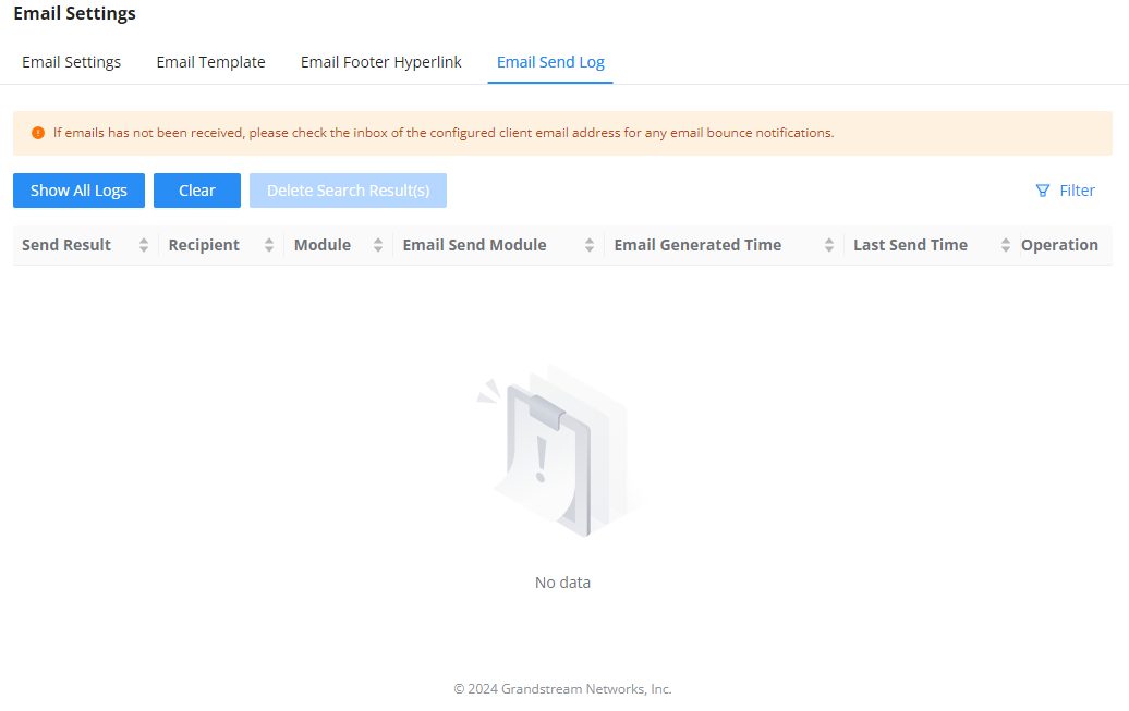
SMS Settings
The SMS feature allows the user to send information over SMS to mobile numbers. Currently, the information which can be sent over SMS are the following:
- Profile Code:
- Verification Code:
- Alarm Notification:
SMS Settings
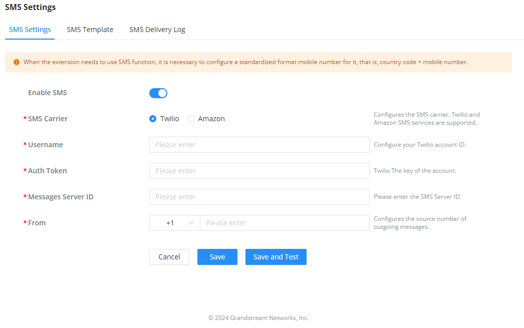
Twilio:
Enable SMS | Toggle the slider to enable/disable SMS service. |
SMS Carrier | Select Twilio as the SMS Carrier. |
Username | Enter the username of the account of the carrier. |
Auth Token | Enter the authentication token generated on the carrier’s site. |
Message Server ID | Enter the ID of the message server of the carrier. |
From | Configure the source number of the outgoing messages. |
Amazon:
Enable SMS | Toggle the button to enable/disable SMS feature. |
SMS Carrier | Choose Amazon as the SMS carrier. |
Region | Choose your region.
|
Username | Configure your Amazon account ID. |
Password | Configure your Amazon account password. |
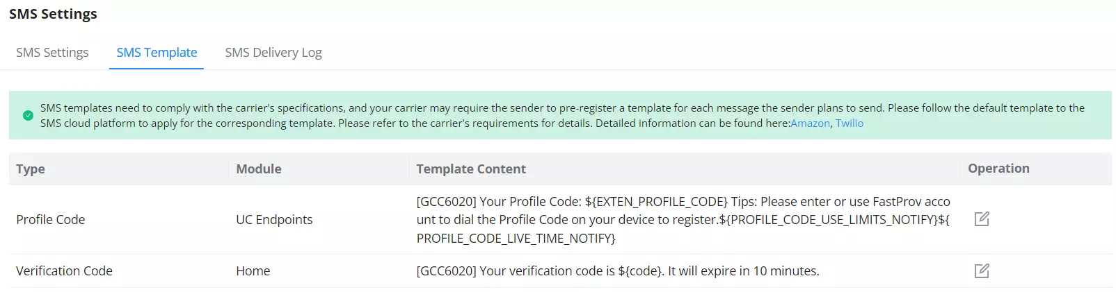
SMS Template
In the “SMS Template” tab, the user can view and edit templates of the SMS messages sent by the GCC device.
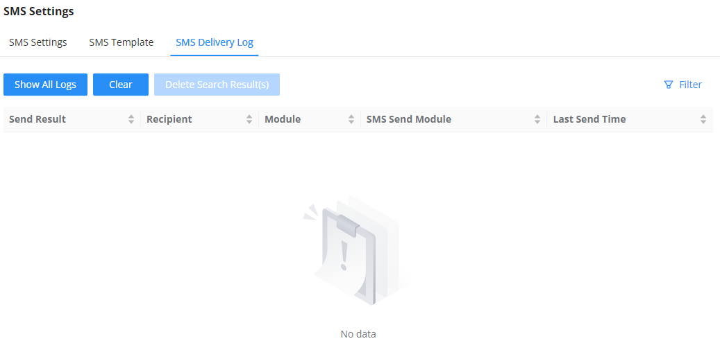
SMS Delivery Log
The “SMS Delivery Log” tab displays information about all the SMS messages that have originated from the GCC device.
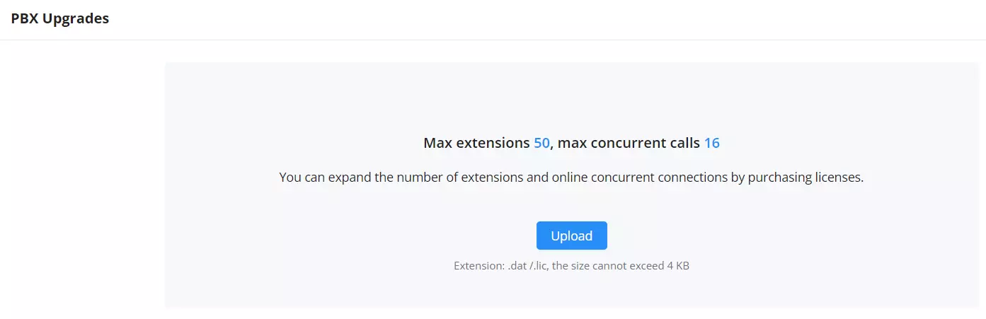
PBX Upgrades
On this page, the user can manage the license for upgrading the PBX capabilities of the GCC. When the license file is acquired, the user can upload the license file in this section.
Maintenance
Upgrade
When a new firmware is released for the GCC device, the user can use the “Upgrade” page to update the firmware of the GCC device using different methods of updating the firmware.
There are three methods of upgrading the firmware which are listed below.
- Official Online Upgrade: This method allows upgrading directly from the Grandstream firmware server. The administrator can click “Detect New Version” to check for any new firmware releases. When a new firmware version is available, the administrator can proceed with upgrading the device.
- Allow DHCP Options 43 and 66 to Override Server: If enabled, DHCP options 66 and 43 will override the upgrade and provisioning settings, if disabled, use the configured server path to request firmware information by default. Note: In the official online upgrade mode, “Detect New Version” uses the official default address, and this configuration does not take effect.
- Check/Download New Firmware at Bootup: When it is turned on, firmware detection will be performed every time the device is started. If a new firmware version is detected, it will automatically download and upgrade. This option is disabled by default to prevent the device from updating upon booting.
- Scheduled Upgrade: Specifies a specific schedule for the device to check for new firmware and install them.
- Upgrade via Network: Using this method, the user can choose a specific upgrade method and configure a server address that hosts the firmware files.
- Upgrade via Manual Upload: Using this method, the user can upload the firmware file directly on the web UI of the device.
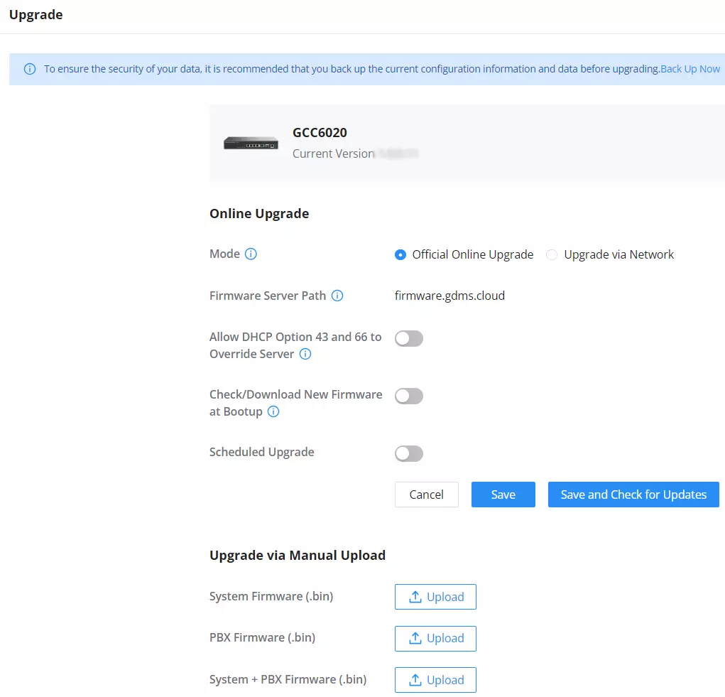
Parameter | Description |
Online Upgrade | |
Mode |
|
Allow DHCP Option 43 and 66 to Override Server | If enabled, DHCP options 66 and 43 will override the upgrade and provisioning settings. If disabled, use the configured server path to request firmware information by default. Note: In the official online upgrade mode, “Detect New Version” uses the official default address, and this configuration does not take effect. |
Check/Download New Firmware at Bootup | When it is turned on, firmware detection will be performed every time the device is started. If a new firmware version is detected, it will automatically download and upgrade |
Scheduled Upgrade | Enable this option and select the schedule for checking if there is a new firmware version. If a new version is detected, the device will perform the update according to the schedule. |
Upgrade via Manual Upload | |
System Firmware (.bin) | Upgrade the system’s firmware by uploading the firmware image. Only .bin file extensions are allowed. |
PBX Firmware (.bin) | Upgrade the PBX’s firmware by uploading the firmware image. Only .bin file extensions are allowed. |
Firmware (.bin) | Upgrade both the system and PBX firmwares by uploading one firmware file. Only .bin file extensions are allowed. |
Backup & Restore
On the “Backup & Restore” page, the user can back up the data of the GCC device manually or using a scheduled backup.
The restore function allows the import of a backup file to restore the GCC.
When backing up the data, the user can choose the data of the GCC modules to be backed up.
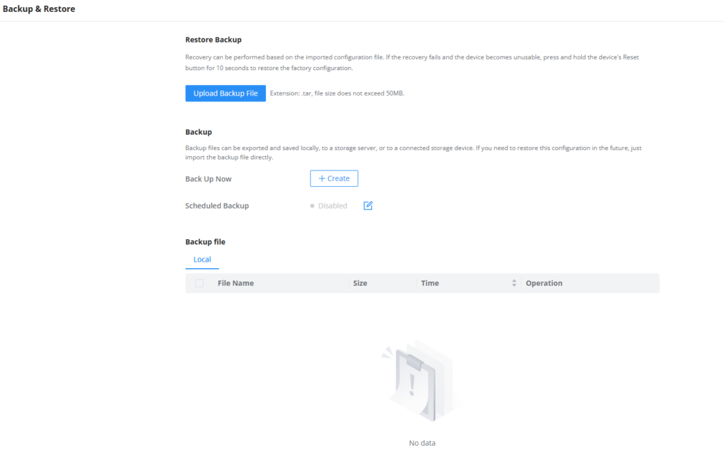
Restore Backup
Press the “Upload Backup File” button to import a previously saved backup file from your computer.

Backup
Backup files can be exported and saved locally, to a storage server, or to a connected storage device.
The administration can select the time to back up as follows
Back up Now: Press  button to initiate an immediate backup.
- Choose Storage Location: Local or Storage Server.
- Storage Location: Local.
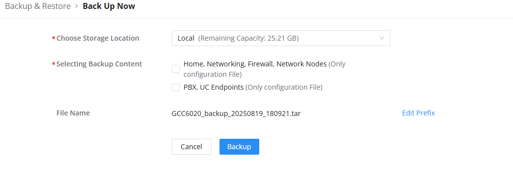
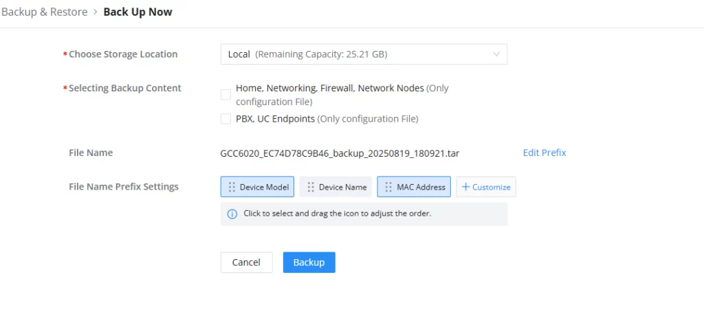
Clicking on “Edit Prefix” allows the user to select the prefixes to include in the name of the backup file for easier identification of the device corresponding to the backup file. The preset prefixes are Device Model, Device Name, and MAC Address. The user can also add a customized prefix.
- Storage Location: Storage Server.
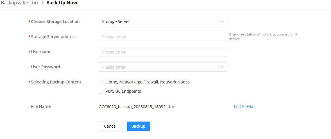
Enter the Storage Server Address, Username, and Password.
2. Select the backup Content. (Home, Networking, Firewall, Network Node and/or PBX, UC Endpoints).
Scheduled Backup: Press  to create a new backup schedule.
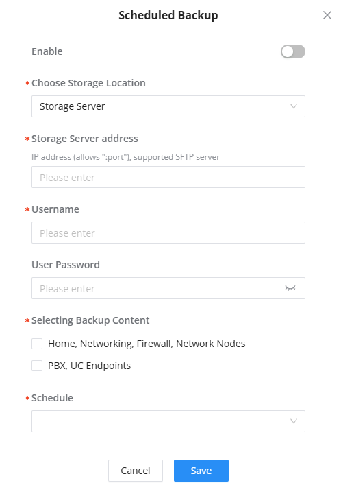
- Check “Enable” to enable the backup schedule.
- Choose Storage Location: Storage Server (only)
- Storage Server Address: Enter the IP address:port of the SFTP server.
- Username: Enter the SFTP server username.
- User Password: Enter the SFTP server password.
- Select the backup content (Home, Networking, Firewall, Network Nodes and/or PBX, UC Endpoints).
- Schedule: Select a schedule. If no schedule is defined, press the “New Schedule” button to create it.
Backup file: List the local backup files.
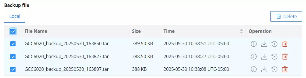
Administrators can operate them as follows:
 : To check the details.
 : To download the backup file to a local computer.
 : To restore the local backup file.
 : To delete the backup file.
 : Select multiple backup files and batch delete them.
Factory Reset
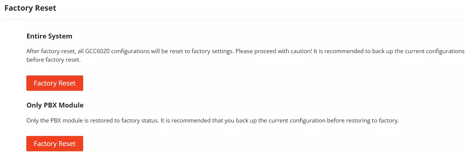
On this page, the user can perform a factory reset for the entire system. This will delete all the modules’ data and configuration which are stored on the local storage of the device. If the user uses the “Factory Reset” button under Only PBX Module, only the data and configuration in the PBX module will be deleted. The other modules are not affected by this action.
Notification Center
The Notification Center allows the user to view and configure notifications of the events that occur on the GCC device. To access the notification center, please access the main page of the GCC web UI and then click on the Notification Center tab.
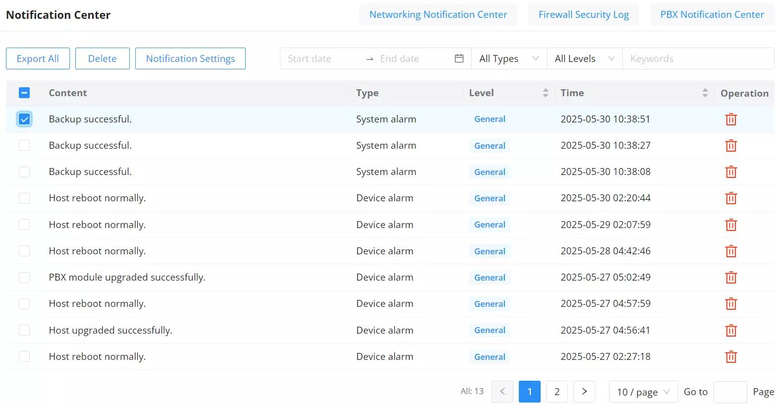
Notification Settings
To set the notifications of the GCC device, click on  .
.
On this page, the user can enable notifications for certain events on the GCC. In addition to generating the notification on the web UI, the user can configure an email address to which email notifications are sent.
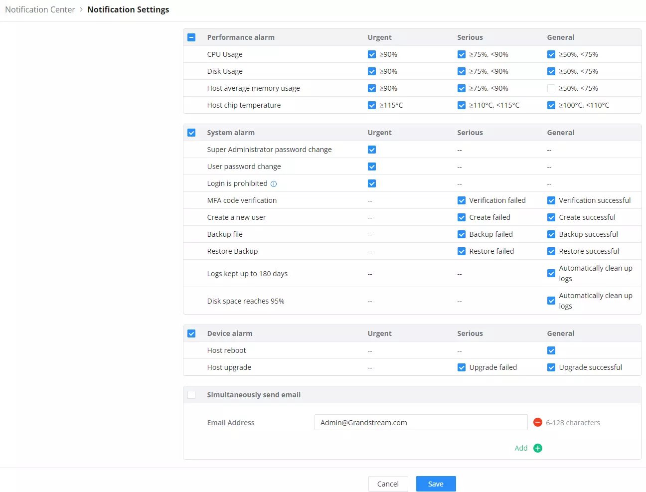
Logs & Diagnostics
Operation Log
The Operation Log page provides administrators with a comprehensive overview of all logged operations, offering detailed information about each activity. This feature ensures transparency and allows administrators to monitor, analyze, and manage system activities effectively.
From this page, the administrator can monitor system operations, including login actions and their outcomes (success or failure), date/time, IP address, username, and Page. Additionally, the administrator can add remarks for each action by editing the remark column using the provided button .

The administrator can utilize filters to quickly find the needed information.
The supported filters are:
- Date: Specify a Start date and End date to narrow down results.
- Operation Terminal: Choose from All Operation Terminals, Local, GDMS Networking, Manager, or CLI.
- Module: Filter by specific module such as All Modules, Home, Networking, Firewall, or Network Nodes.
- Username / IP Address: Enter the username or IP address for precise filtering.
 on the top right corner to access the PBX Operation Log module.
To export the logs, press  button. The logs will be saved in a CSV file.
System Logs
The System Logs page allows administrators to view, download, and forward system log data to an external server for monitoring and troubleshooting.
The page is divided into two parts:
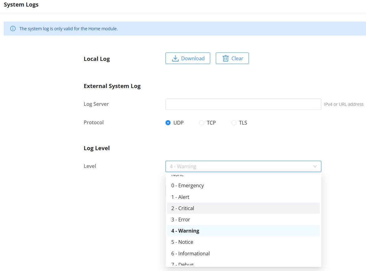
- Local Log
Users can download or clear the current system log file directly from the device. - External System Log
Allows forwarding logs to a remote server. Enter the destination server address and select the desired protocol:- UDP
- TCP
- TLS
You can also define the Log Level, which filters the types of events that are captured and sent. Available log levels are:
- None
- 0 – Emergency
- 1 – Alert
- 2 – Critical
- 3 – Error
- 4 – Warning
- 5 – Notice
- 6 – Informational
- 7 – Debug
Select the appropriate level based on the desired granularity of system reporting.
Core Files
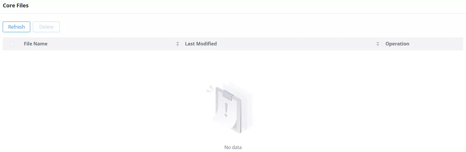
The Core Files page displays a list of crash dump files generated by the system in the event of a critical failure. These files contain technical information that can help developers or support teams diagnose system issues.
If the device has not experienced any crashes, this page will appear empty.
Users can:
- Click Refresh to check for newly generated files.
- Select and Delete any stored files if needed.
NETWORKING
The Networking module of GCC6020 includes network-related configuration mainly VPN, Multi-WAN, and traffic management. It also allows users to configure all the standard routing configurations such as VLAN, port forwarding, etc.
Click on the icon to access. 
FIREWALL
The firewall module of GCC device is a Next-Generation Firewall (NGFW) that secures users’ network environment by providing defense against the most advanced network attacks as it supports anti-virus and intrusion prevention (IDS/IPS) with frequent signature library updates and also supports SSL proxy to filter HTTPS URL.
Click on the icon to access. 
NETWORK NODES
Network nodes refer to individual devices or components such as switches and access points that form the interconnected infrastructure of the network. These nodes provide data points for analysis, which helps centralize the monitoring and configuration of the device performance, security, and overall network features. The GCC device offers an embedded controller for both the wireless access points and the GWN-managed network switches to provide the user with a global overview of his network infrastructure.
Click on the icon to access. 
PBX
The integrated IPPBX module in the all-in-one convergence device the GCC device provides a communication and collaboration solution for enterprises that do not require expanded telephony capabilities. It offers the same features that are provided by Grandstream IPPBX solution, the UCM6300, to ensure cost-effective and efficient collaboration among professionals.
Click on the icon to access. 
UC ENDPOINTS
The UC endpoints configuration module contains all the settings and tools to manage and control the unified communication endpoints, including devices ranging from IP phones, Video phones, and Wi-Fi phones, to security facility access devices such as the IP cameras and the door systems. The GCC device with its VoIP devices and IPC devices management modules offers a centralized way to manage, provision, and control all your on-premise UC endpoint devices.
Click on the icon to access. 
CHANGE LOG
This section documents significant changes from previous versions of user manuals for GCC6020. Only major new features or major document updates are listed here. Minor updates for corrections or editing are not documented here.
Firmware version 1.0.7.69 (PBX version 1.0.27.94)
System:
- Ports 25 – 27 can now be configured as WAN ports [Technical Specifications]
- “User Management” page has been renamed to “Administrator”. An additional column “Home Permission” has been added to the “Role” page [Administrator]
Firewall:
- Added Permission Management section [PERMISSION MANAGEMENT]
Networking:
- Ports 25 – 27 can now be configured as WAN ports [WAN]
- Added Permission Management section [PERMISSION MANAGEMENT]
Network Nodes:
- Added Permission Management section [PERMISSION MANAGEMENT]
Firmware version 1.0.7.59 (PBX version 1.0.27.94)
System:
- Added “Identity Name” information column on the Client page. [Clients]
- Added support for Bridge mode [Bonjour Gateway]
PBX:
- No major changes.
Firmware version 1.0.7.48 (PBX version 1.0.27.90)
System:
- Added support for GDMS new IPsec option “Add Router LAN address”, which will allow the router to use its own LAN address to configure local subnet for VPN.
- Added support for [USB 4G/5G dongle].
PBX:
- No major changes.
Firmware version 1.0.7.46 (PBX version 1.0.27.90)
System:
- No major changes.
PBX:
- No major changes.
Firmware version 1.0.7.44 (PBX version 1.0.27.89)
- Security version is now displayed on the Overview page. [Overview]
- Added prefix configuration for the filename of the backup file. [Backup]
- Added firewall enabling configuration and local inbound policy configuration to the setup wizard. [Setup Wizard]
Firmware version 1.0.7.32 (PBX version 1.0.27.70)
System:
- This is the initial version.
PBX:
- This is the initial version.
Microsoft® is a registered trademark of Microsoft Corporation in the United States and/or other countries. All other trademarks and registered trademarks are the property of their respective owners.