
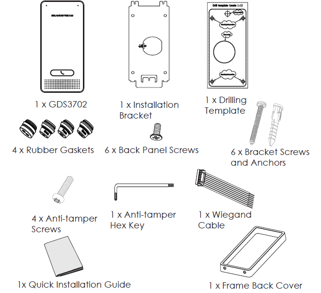
PACKAGE CONTENTS
MOUNTING GDS3702
On-Wall (Surface) Mounting
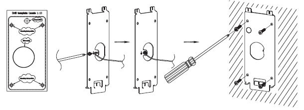
Step 1:
Refer to the “drilling template” to drill holes at the targeted place on the wall then mount the installation bracket using the four screws and anchors provided (screwdriver not provided). Connect and tighten the “Ground” wire to the bracket ground marked with the printed icon  .
.
Step 2:
Pull Cat5e or Cat6 cable (not provided) through the rubber gasket selecting the correct size and the back cover panel piece, please refer to the GDS3702 WIRING TABLE at the end of QIG for Pin connections.
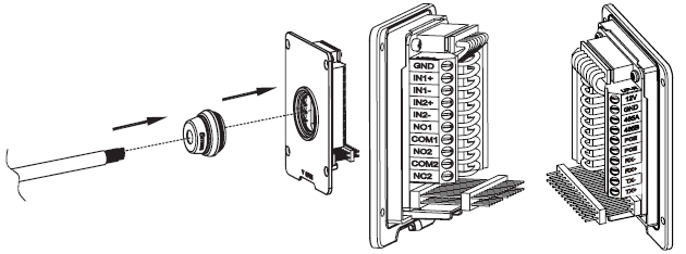
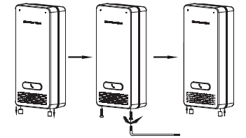
Step 3:
Make sure the ”Back Cover Frame” is in place, the wired back cover panel is good. Flush the back cover panel piece with the whole back surface of the device, and tighten it using the screws provided.
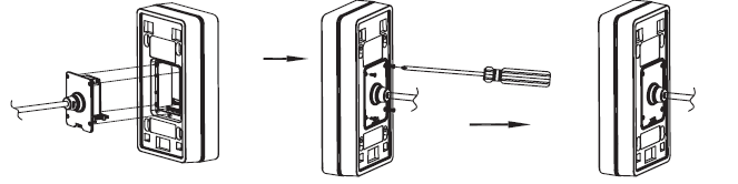
Step 4:
Take out the two preinstalled anti-tamper screws using the hex key provided. Carefully align the GDS3702 to the metal bracket on the wall, press, and pull the GDS3702 down to the right position.
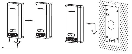
Step 5:
Install the two anti-tamper screws back using the hex key provided (do NOT over-tighten the screws). Cover the two screw holes on the bottom of the “Back Cover Frame” piece using the two silicon plugs provided. Final check and finish the installation.
In-Wall (Embedded) Mounting
Please refer to the “In-Wall (Embedded) Mounting Kit”, which can be purchased separately from Grandstream.
CONNECTING THE GDS3702
Refer to the illustration below and follow the instructions on the next page.
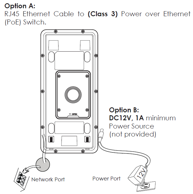
Option A
Plug an RJ45 Ethernet cable into the (Class 3) Power over Ethernet (PoE) switch.
Option B
Step 1:
Select an external DC12V, minimum 1A power source (not provided). Wire correctly the “+,-” cable of the power into the “12V, GND“ connector of the GDS3702 socket (refer to the previous mounting page for instruction). Connect the power source.
Step 2:
Plug an RJ45 Ethernet cable into a network switch/hub or router.
GDS3702 CONFIGURATION
The GDS3702 is by default configured to obtain the IP address from the DHCP server where the unit is located.
In order to know which IP address is assigned to your GDS3702, please use the GS_Search tool as illustrated in the following steps.
Step 1:
Download and install GS_Search tool:
https://www.grandstream.com/support/tools
Step 2:
Run the Grandstream GS_Search tool on a computer connected to same network/ DHCP server.
Step 3:
Click on ![]() button to start the device detection.
button to start the device detection.
Step 4:
The detected devices will appear in the output field as below.
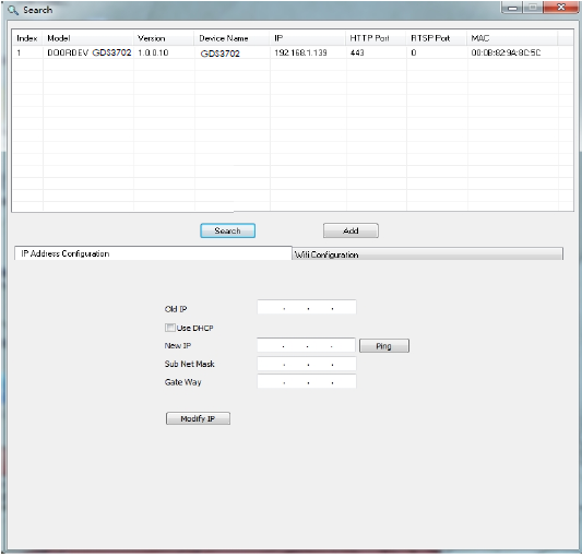
Step 5:
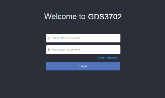
Open the web browser and type the displayed IP address of GDS3702 with the leading https:// to access the web GUI. (For security reasons, the default web access of GDS3702 is using HTTPS and port 443).
Step 6:
Enter the username and password to log in.
(The default administrator username is “admin” and the default random password can be found on the sticker on the GDS3702).
Step 7:
After login into the web GUI, click the left side menu in the web interface for more detailed and advanced configuration.
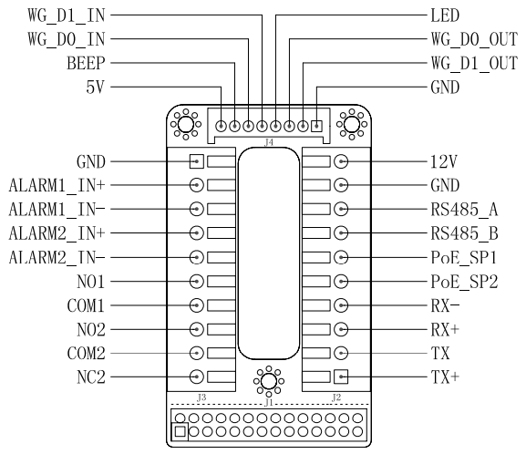
GDS3702 WIRING TABLE
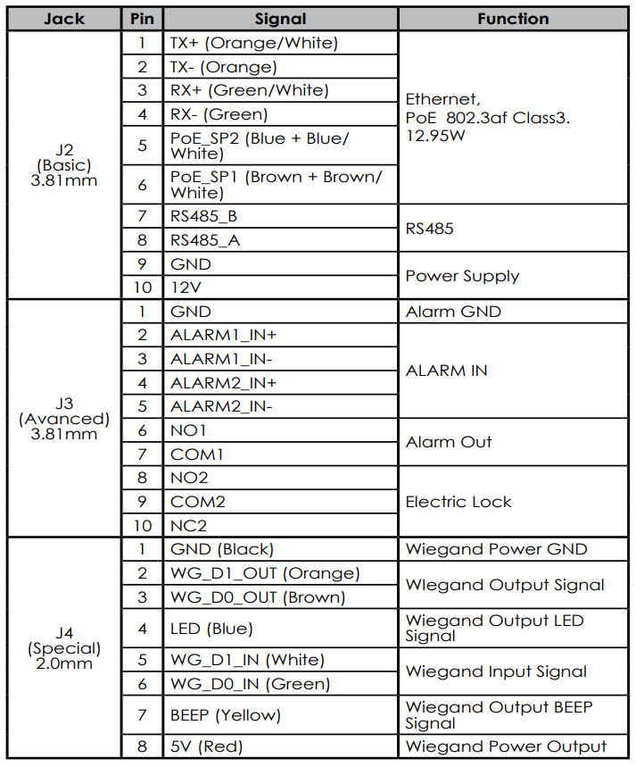
For more details regarding GDS3702 wiring, please refer to User Manual.
Note:
- Power PoE_SP1, PoE_SP2 with DC, the voltage range is 48V~57V, no polarity.
- Power with PoE the cable wiring:
- PoE_SP1, brown and brown/white binding
- PoE_SP2, blue and blue/white binding
- DC Power could be correctly sourced from a qualified PoE Injector.