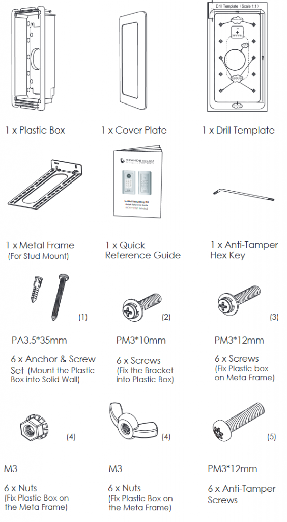
Package Contents
Solid Wall Installation
Please follow below steps to install the device into solid wall.
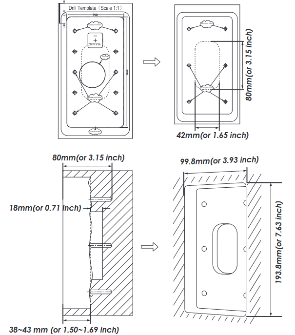
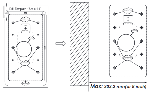
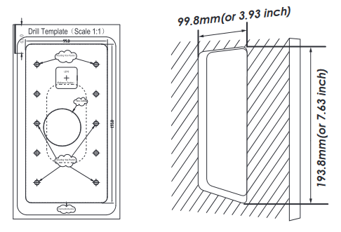
Step 1: Use provided Drill Template to mark boundary then drill holes for the 6 mounting screws and the circular hole for wiring. (drilling or dig tools not provided) Then dig a rectangle hole for the box with depth around 38~43 mm (or 1.50~1.69 inch), refer to mark in the template (rotating it to measure if necessary).
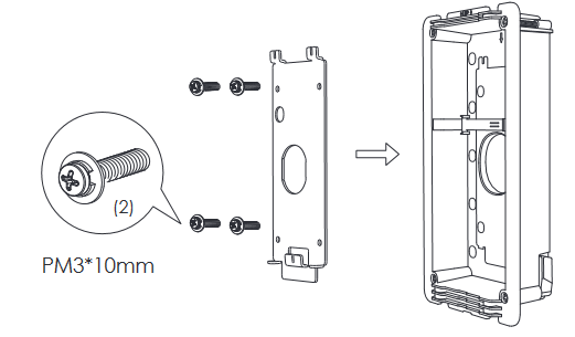
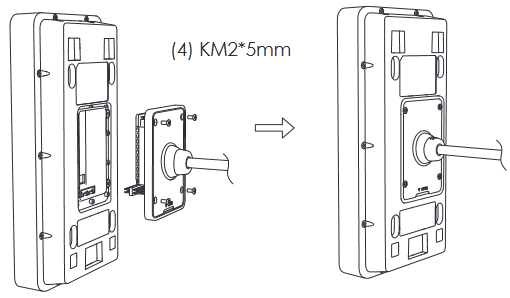
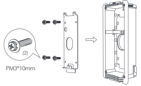
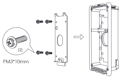
Step 2: Mount the Installation Bracket into the Plastic Box using supplied Screws(2).
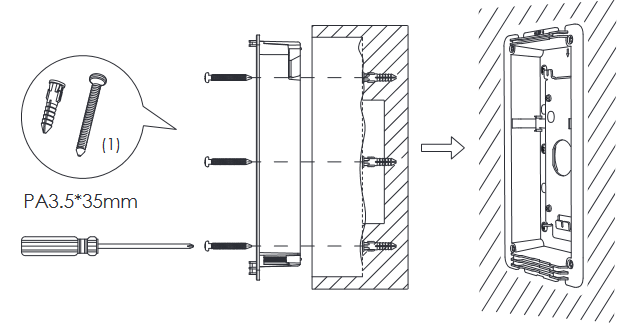
Step 3: Use provided Anchor/Screw(1) to mount the Plastic Box inside the hole just dug.
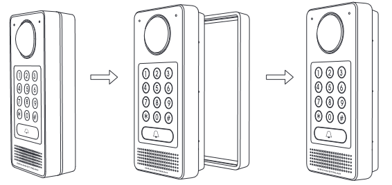
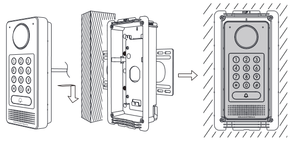
Step 4: Remove the frame back cover (designed for Surface/On-Wall Installation).
Step 5: Follow GDS37XX QIG and User Manual to connect wires to the PoE switch or PoE Injector. Connect the Electrical Lock wiring according to its document.
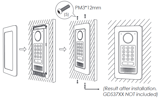
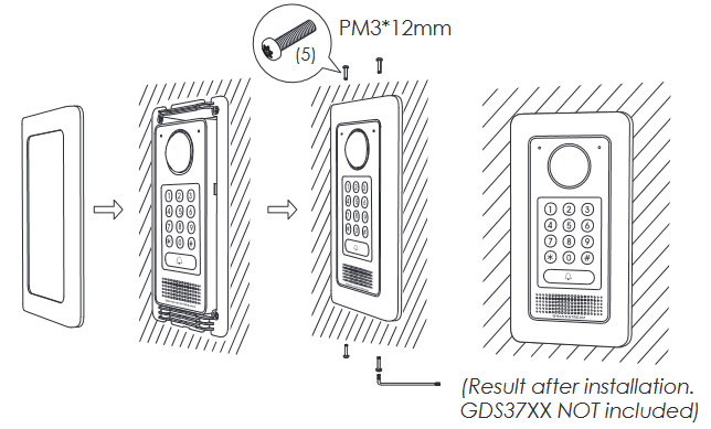
Step 6: Align the GDS37XX with the bracket, press and push down the GDS37XX into place.
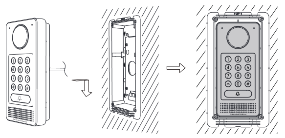
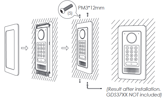
Step 7: Install the Cover Plate and fix it using the Hex Key with the Anti-Tamper Screws(5) provided.
Stud Installation
Please follow below steps to install the device at the stud of a new building open wall, or a finished wall.
Step 1: For finished wall, use provided Drill Template to mark boundary and dig a rectangle hole into the wall. For open wall, skip and go to next step.
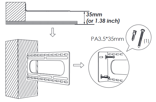
Step 2: Install the Metal Frame with short edge to the stud using the set of Anchor/Screw(1) provided.
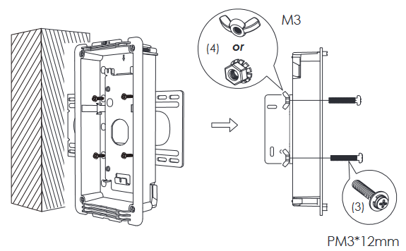
Step 3: Mount the Installation Bracket into the Plastic Box using supplied Screws(2).
Step 4: Use provided Screws and Nuts(3)(4) to install the Plastic Box on the long edge of the Metal Frame. Choose either set of Nuts(4) with convenience.
Step 5: Remove the frame back cover (designed for Surface/On-Wall Installation).
Step 6: Follow GDS37XX QIG and User Manual to connect wires to the PoE switch or PoE Injector. Connect the Electrical Lock wiring according to its document.
Step 7: Align the GDS37XX with the bracket, press and push down the GDS37XX into place.
Step 8: Install the Cover Plate and fix it using the Hex Key with the Anti-Tamper Screws(5) provided.
Drywall (Hollow Wall) Installation
Please follow below steps to install the device on a drywall or hollow wall. The thickness of the wall where the clamps can handle is among 6.2 ~ 24 mm (or 0.24 ~ 0.94 inch)
Step 1: Use provided Drill Template to mark boundary then cut opening on the dry wall. Do NOT over cut. (wall cutting tools not provided)
Step 2: Mount the Installation Bracket into the Plastic Box using supplied Screws(2).
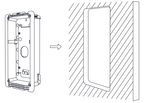
Step 3: Insert the Plastic Box into the cut hole properly.
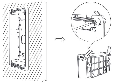
Step 4: Tighten the four clamps alternately in diagonal to mount the Plastic Box on the wall. Please do NOT over tighten to avoid damaging the wall or clamp.
Step 5: Remove the frame back cover (designed for Surface/On-Wall Installation).
Step 6: Follow GDS37XX QIG and User Manual to connect wires to the PoE switch or PoE Injector. Connect the Electrical Lock wiring according to its document.
Step 7: Align the GDS37XX with the bracket, press and push down the GDS37XX into place.
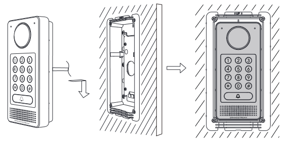
Step 8: Install the Cover Plate and fix it using the Hex Key with the Anti-Tamper Screws(5) provided.