OVERVIEW
The interface board is available for use with the GDS series. Designed for indoor usage this accessory is used to easily facilitate wiring by replacing the default shipped IF board. For indoor installation, users can use this IF board and connect RJ45 cable (existing ethernet cable used in computer) directly into the device and saves the hassle of connecting each individual wire into the wiring socket which could easily create a user error.
 GDS Indoor IF Board | CATEGORY | PARAMETERS |
Compatible Model | GDS3710,GDS3712,GDS3705,GDS3702 | |
Usage Scene | Indoor Usage Only Attention: IP66 NOT Supported in GDS37XX once this board used. | |
Dimension | 62.96mm*44.96mm*27.6mm | |
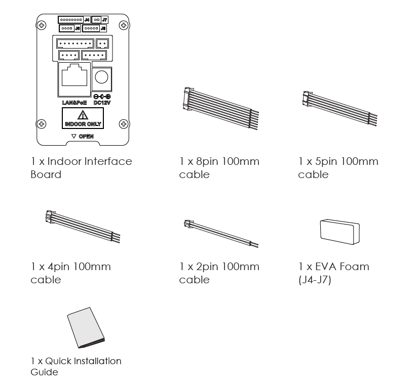
Packing List | 1x Indoor Interface Board (Screws Included) 1x 8pin 100mm cable 1x 5pin 100mm cable 1x 4pin 100mm cable 1x 2pin 100mm cable 1x EVA Foam(Cover J4-J7 Openings) 1x QIG | |
Package | Individually Packed Per Piece 10 Pieces per White Box 10 White Boxes per Cartoon Box Total 100 pieces per Cartoon Box. | |
Features at a Glance
PACKAGE CONTENT
The package content of Indoor interface board comes with the following :
- 1x Indoor Interface Board (Screws Included)
- 1x 8pin 100mm cable
- 1x 5pin 100mm cable
- 1x 4pin 100mm cable
- 1x 2pin 100mm cable
- 1x EVA Foam(Cover J4-J7 Openings)
- 1x QIG
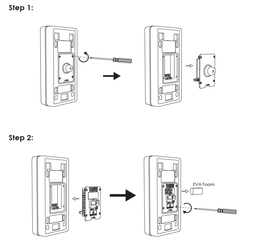
MOUNTING INDOOR INTERFACE BOARD
The below illustrations display the steps for mounting the indoor interface board :
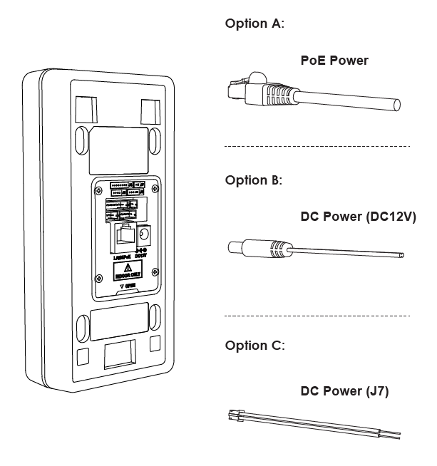
POWER INPUT FOR GDS37xx
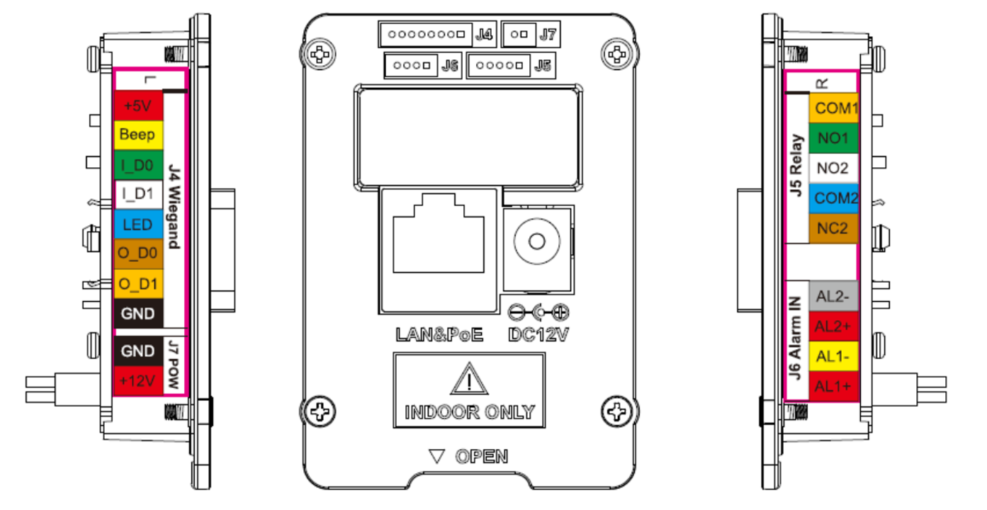
GDS Indoor IF Board Pin Definition
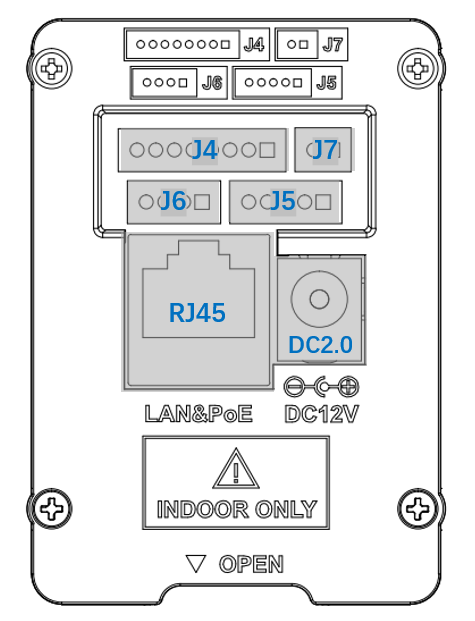
Jack | Pin | Signal | Function |
RJ45 | / | / | Ethernet, PoE 802.3af Class3. 12.95W |
DC2.0 | / | / | 12V DC Power Input |
J7 | 1 | 12V(Red) | 12V DC Power Input |
2 | GND(Black) | ||
J5 | 1 | COM1(Orange) | Alarm Out |
2 | NO1(Green) | ||
3 | NO2(White) | Electric Lock | |
4 | COM2(Blue) | ||
5 | NC2(Brown) | ||
J6 | 1 | ALARM2_IN-(Brown) | Alarm In
|
2 | ALARM2_IN+(Red) | ||
3 | ALARM1_IN-(Yellow) | ||
4 | ALARM1_IN+(Red) | ||
J4 | 1 | GND(Black) | Wiegand Power GND |
2 | WG_D1_OUT(Orange) | WIegand Output Signal | |
3 | WG_D0_OUT(Brown) | ||
4 | LED(Blue) | Wiegand Output LED Signal | |
5 | WG_D1_IN(White) | Wiegand Input Signal
| |
6 | WG_D0_IN(Green) | ||
7 | BEEP(Yellow) | Wiegand Output BEEP Signal | |
8 | 5V(Red) | Wiegand Power Output |
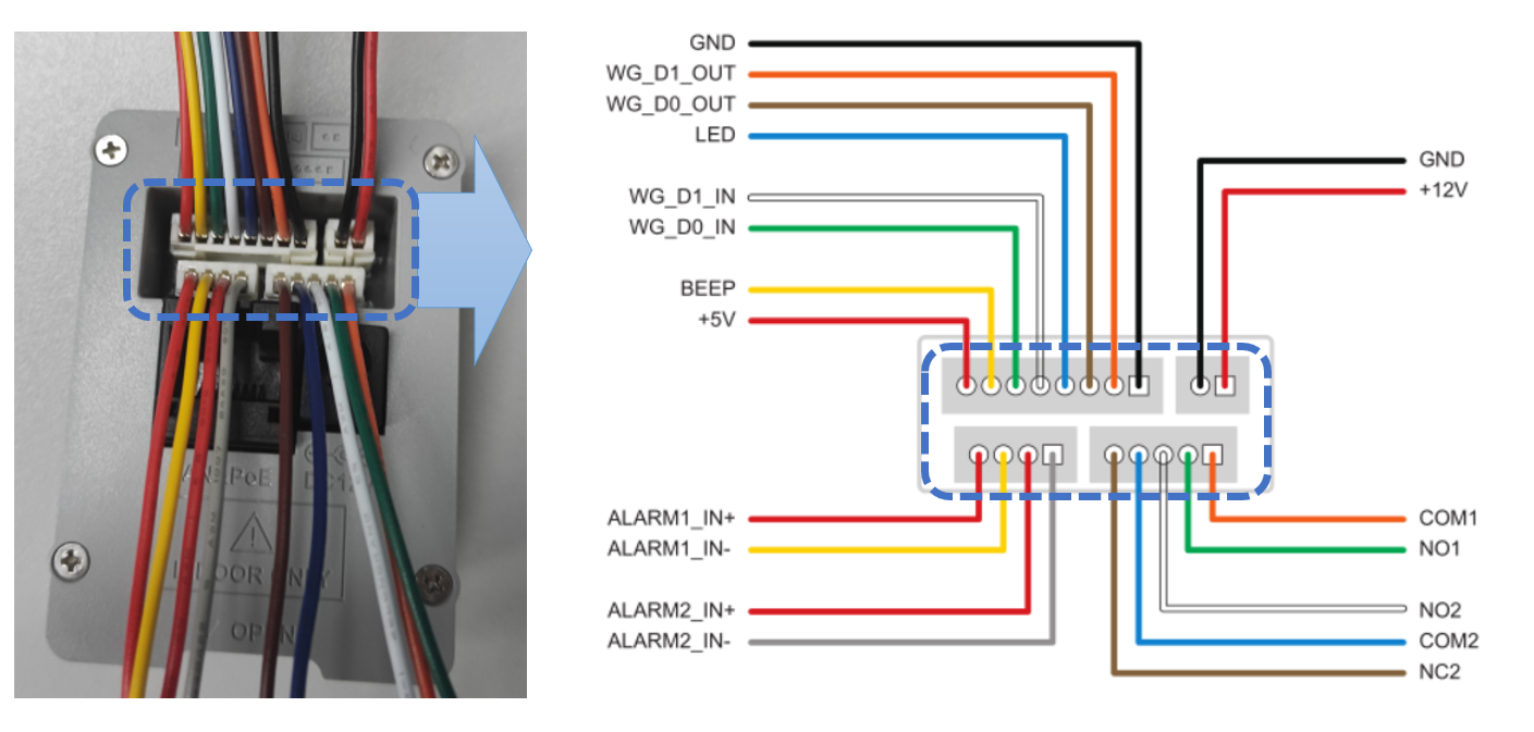
GDS Indoor IF Board Pin Definition
GDS37xx Indoor IF Board Connector J4,J5,J6,J7 Pin Definition
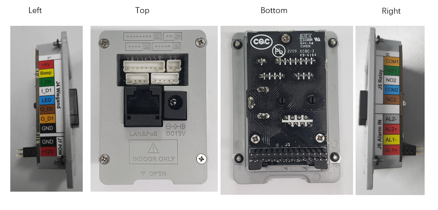
GDS37xx Indoor IF Board Illustration
GDS Indoor IF Board Pin Label for Connections