
INTRODUCTION
GDS37xx is an audio/video door access system, an innovative IP-based powerful door system. The GDS37xx was built for users looking for a robust audio/video facility access and security monitoring solution that can be deployed in environments of all sizes.
This guide explains how to use the GDS37xx digital Input and its related configuration.
FUNCTIONALITY
The GDS37xx can be used with two input peripherals (Digital Input 1 and Digital Input 2) allowing more possibilities for deployments. When the input peripheral is activated, a signal is sent to the GDSD37xx, and depending on the configuration chosen the following actions can be executed:
If the GDS37xx Digital Input is configured as an Alarm Input then it can generate a trigger to activate a preconfigured alarm profile to notify the user.
WIRING DIAGRAM
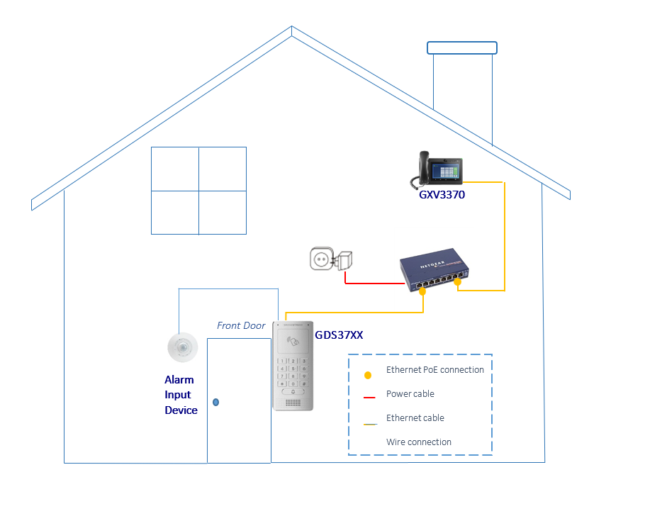
In the below example, we assume that the GDS3705 is installed on a small warehouse at the front door and the GXV IP phone along with a motion sensor is set to alert the user via a call if someone gets close to the motion sensor zone.
GDS37xx WIRING CONNECTION
Connecting Alarm Input PINs
The GDS37xx has two alarm input entries two alarm output entries and a ground entry as shown in the following figure.
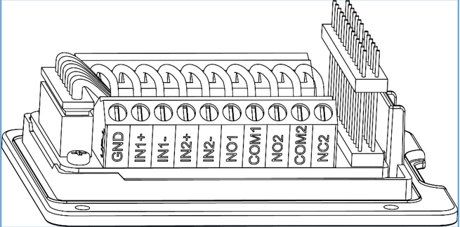
Note: Alarm IN is just an electronic lock, they are either open to block the current or close to let the current pass through, therefore a 3rd party power supply is needed to power the device connected to the GDS37xx via Alarm IN.
Alarm IN Connection Example
Connect Alarm (IN1+, IN1-) or (IN2+, IN2-) to appropriate wires to receive the signal from the third party device as shown below.

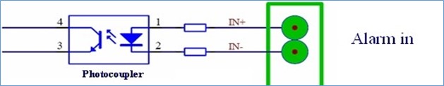
Alarm Input Circuit
Alarm Input could use any 3rd party Sensors (like IR Motion Sensor, door sensor, etc).
The figure below shows an illustration of the Circuit for the alarm input.
GDS37xx Web Configuration
Alarms can be triggered either by motion detection (using the GDS371x’s camera) or digital input. Users can configure the GDS37xx events to trigger programmed actions within a predefined schedule.
To configure the digital input, the hardware wiring needs to be done, then the configuration can be followed from the web GUI> Alarm Settings > Alarm event Config > Digital Input as shown in the screenshot:
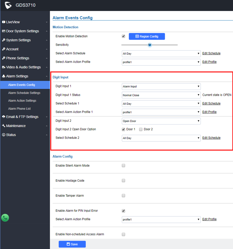
The Alarm Input option will prompt a new menu called Digit Input x Status to select the status of the Alarm Input peripheral. Two options can be selected:
- Normal Open: The configured alarm will be triggered when Digital Input Status switches from Close to Open.
- Normal Close: The configured alarm will be triggered when Digital Input Status switches from Open to Close.
If the GDS37xx Digital Input is configured to Open Door then a connected switch can be used to open door (door 1 or door 2 can be selected) from inside.
If the GDS37xx Digital Input is configured as Abnormal Door Control then when a device is being tampered with to open the door abnormally a siren alarm can be used to notify the user. For detailed information please refer to GDS37xx User Manual, “Siren alarming when the door opened abnormally” configuration.
The Digital input option leverages the Select Schedule and the Select alarm action profile options to provide a granular configuration of the specific time to run the alarm and the alarm type used.
Configuration Example
For this example, we’ll set the GDS37xx to initial a call to a sip phone whenever it detects any movement on Sundays.
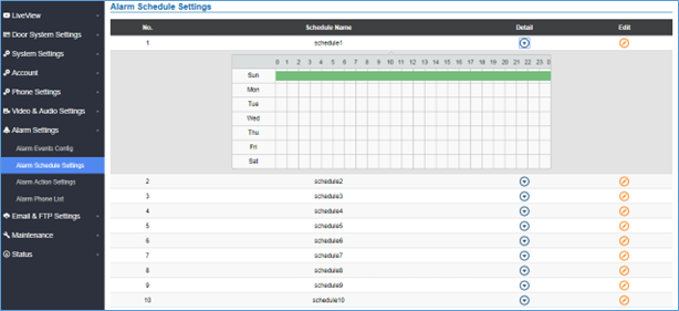
For this configuration, the wiring needs to be done as explained in the previous section (Alarm IN Connection Example). We’ll use for this example Alarm IN1 – and Alarm IN1 + to connect the sensor, then we’ll configure Digit Input 1 as Digital Input, and Digit Input 1 Status as normally closed. And after that, we’ll configure Schedule1 to select Sunday and select it under Select Alarm Schedule, as shown in this screenshot:
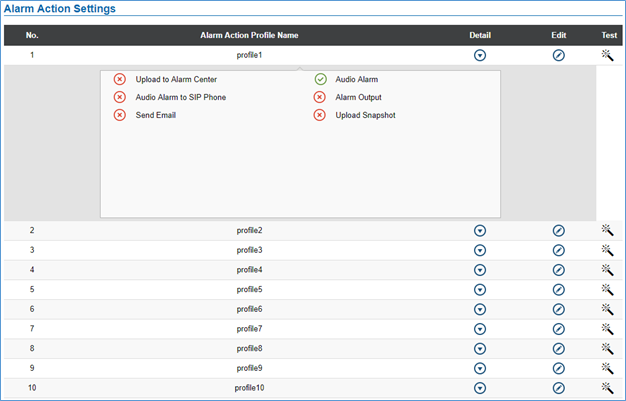
Next, we’ll set Select Alarm Action Profile 1 to profile1, and select Alarm Action Settings on the left sidebar to configure the profile.
The GDS37xx alarms that can be triggered are:
- Upload to Alarm Center: If selected, the GDS Manager will pop up the alarm window and sound the alarm in the computer speaker.
- Audio Alarm to SIP Phone: If selected, GDS37xx will call a pre-configured (video or audio) phone and will play a sound alarm.
- Send Email: If selected, an email with a snapshot will be sent to the pre-configured email destination. (on GDS3710 only)
- Audio Alarm: If selected, GDS37xx will play alarm audio using a built-in speaker.
- Alarm Output: If selected, the alarm will be sent to the equipment (for example Siren) connected to the Alarm Output interface.
- Upload Snapshot: If selected, snapshots at the moment where the event is triggered will be sent to a preconfigured destination e.g. FTP or email. (on GDS3710 only)
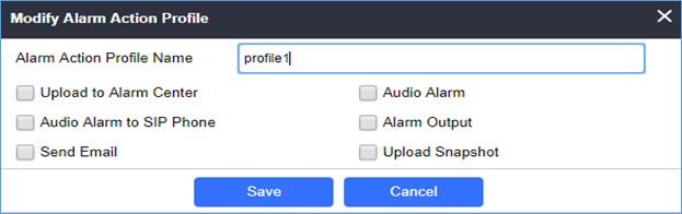
We can edit Profile1 by clicking ![]() button, the following window will pop up, and selecting audio Alarm to SIP Phone,
button, the following window will pop up, and selecting audio Alarm to SIP Phone,
And finally, under Alarm Phone List, we can insert which phone numbers or extensions the GDS3710 will call out when the event is triggered.
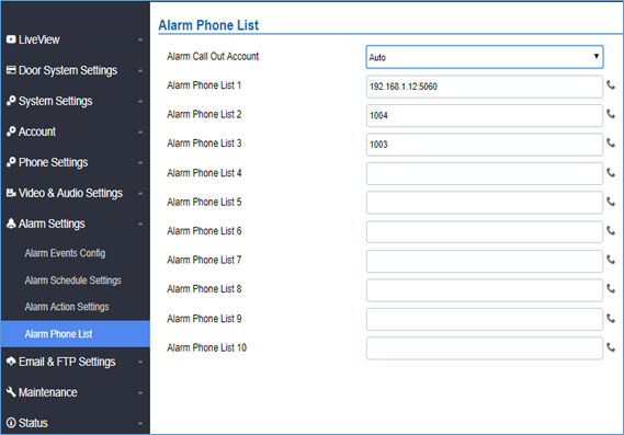
Once the event is triggered, the GDS37xx will call the first number (192.168.1.12), once time out is reached and no answer is returned from the first number, the GDS37xx will try the next number on the list (1004), and so on. Once the remote phone answers the call, an alarm will be played to notify users that an event is triggered.
SUPPORTED DEVICES
The following table shows the supported products and the minimum firmware to use:
Product | Firmware |
GDS3705 | 1.0.1.16 |
| GDS3710 | 1.0.7.23 |
| GDS3712 | 1.0.7.23 |