
GDS3710 HD IP Video Door System is a hemispheric IP video door phone and a high-definition IP surveillance. GDS3710 is ideal for monitoring from wall to wall without blind spots. Powered by an advanced Image Sensor Processor (ISP) and state of the art image algorithms, it delivers exceptional performance in all lighting conditions. The GDS3710 IP video door system features industry-leading SIP/VoIP for 2-way audio and video streaming to smart phones and SIP phones. It contains integrated PoE, LEDs, HD loudspeaker, RFID card reader, motion detector, lighting control switch, Alarm input/output and more.
This guide explains step by step how to use the GDS3710 Input/Output Alarms and related configuration.
GDS3710 WIRING CONNECTION
The first step to setup the GDS3710 in an environment is to choose the powering method then and connect an RJ45 cable so it can interact with the network and start operating. Two ways are possible to power the GDS3710 using PoE or PSU:
Using PoE as power supply (Suggested)
- Connect the other end of the RJ45 cable to the PoE switch.
- PoE injector can be used if PoE switch is not available.
Using the Power Adapter as power supply (PSU not provided)
- Connect the other end of the RJ45 cable to network switch or router.
- Connect DC 12V power source via related cable to the corrected PIN of the GDS3710.
Powering GDS3710
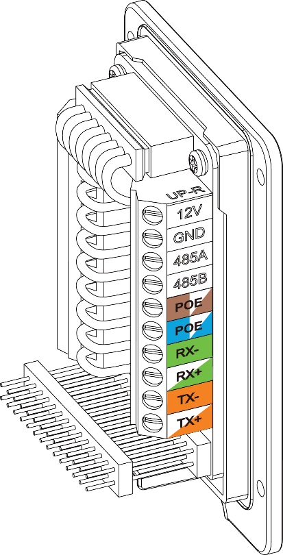
Below figures provide description of wiring connection of the GDS3710 Back Cover to connect the GDS3710 with RJ45 cable and PSU and Alarm for door systems.
Power and Data PINs
To power the GDS3710 using PoE, please follow steps below:
- Cut into the plastic sheath of your RJ45 cable, then unwind and pair the colors like shown below.
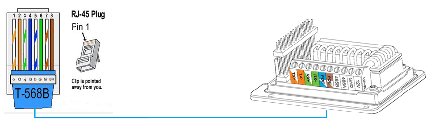
- Connect each color of the RJ45 to its associate on the Back Cover of the GDS3710.
To power the GDS3710 using PSU, please follow steps below:
- Use a multimeter to detect the polarity of your Power Supply, then connect the Back Cover GND to negative pole and 12V to positive pole of the PSU.
- Cut into the plastic sheath of your RJ45 cable, then unwind and pair the colors like shown below

- Connect wires OrangeWhite/Orange and GreenWhite/Green of the RJ45 to its associate on the GDS3710
Connecting Alarm IN and Alarm OUT PINs
The GDS3710 have two alarm input entries and two alarm output entries and a ground entry as shown in the following figure.

The following table summarizes the GDS3710 entries and their purpose.
Jack | Pin | Signal | Function | Note | |
J2 | 1 | TX+ | Ethernet PoE 802.3af Class 3, 12.95W | Orange / White | Data |
2 | TX- | Orange | |||
3 | RX+ | Green / White | |||
4 | RX- | Green | |||
5 | PoE_SP2 | Blue + Blue/White | Please twist these two wires
together and connect to SP1,
SP2 respectively even the PoE NOT used. | ||
6 | PoE_SP1 | Brown + Brown/White | |||
7 | RS485_B | RS485 | |||
8 | RS485_A | ||||
9 | GND | Power Supply | DC 12V, 1A Minimum | ||
10 | 12V | ||||
J3 | 1 | GND | Alarm GND | ||
2 | ALARM1_IN+ | Alarm In | Vin<15V | ||
3 | ALARM1_IN | ||||
4 | ALARM2_IN+ | ||||
5 | ALARM2_IN | ||||
6 | NO1 | Alarm Out | Relay: 30VDC/2A; 125VAC/0.5A | ||
7 | COM1 | ||||
8 | NO2 | Electric Lock | For "Fail Secure" (Locked when Power Lost) Strike, | ||
9 | COM2 | ||||
10 | NC2 | ||||
J4 | 1 | GND | Wiegand Power | Black | Both Input and Output |
2 | WG_D1_OUT | Wiegand Output | Orange | GDS3710 function as Output | |
3 | WG_D0_OUT | Brown | |||
4 | LED | Wiegand Output | Blue | For External Card Reader; Or | |
5 | WG_D1_IN | Wiegand Input | White | For External Card Reader Connect Pin 1,4,5,6,7,8 | |
6 | WG_D0_IN | Green | |||
7 | BEEP | Wiegand Output | Yellow | For External Reader Only | |
8 | 5V | Wiegand Power | Red | For External Card Reader | |
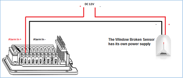
Alarm IN Connection Example
Connect Alarm (IN1+, IN1-) or (IN2+, IN2-) to appropriate wires in order to receive signal from the third party device as shown below.
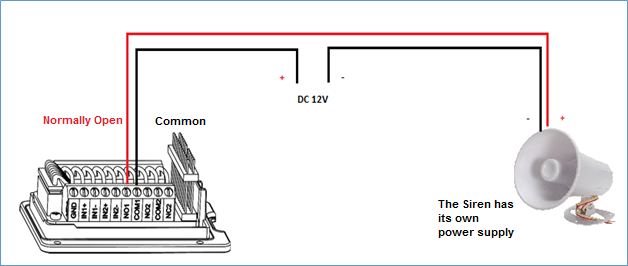
Alarm OUT Connection Example
Connect Alarm (NO1, COM1) to appropriate wires in order to receive signal from the third party device as shown below.
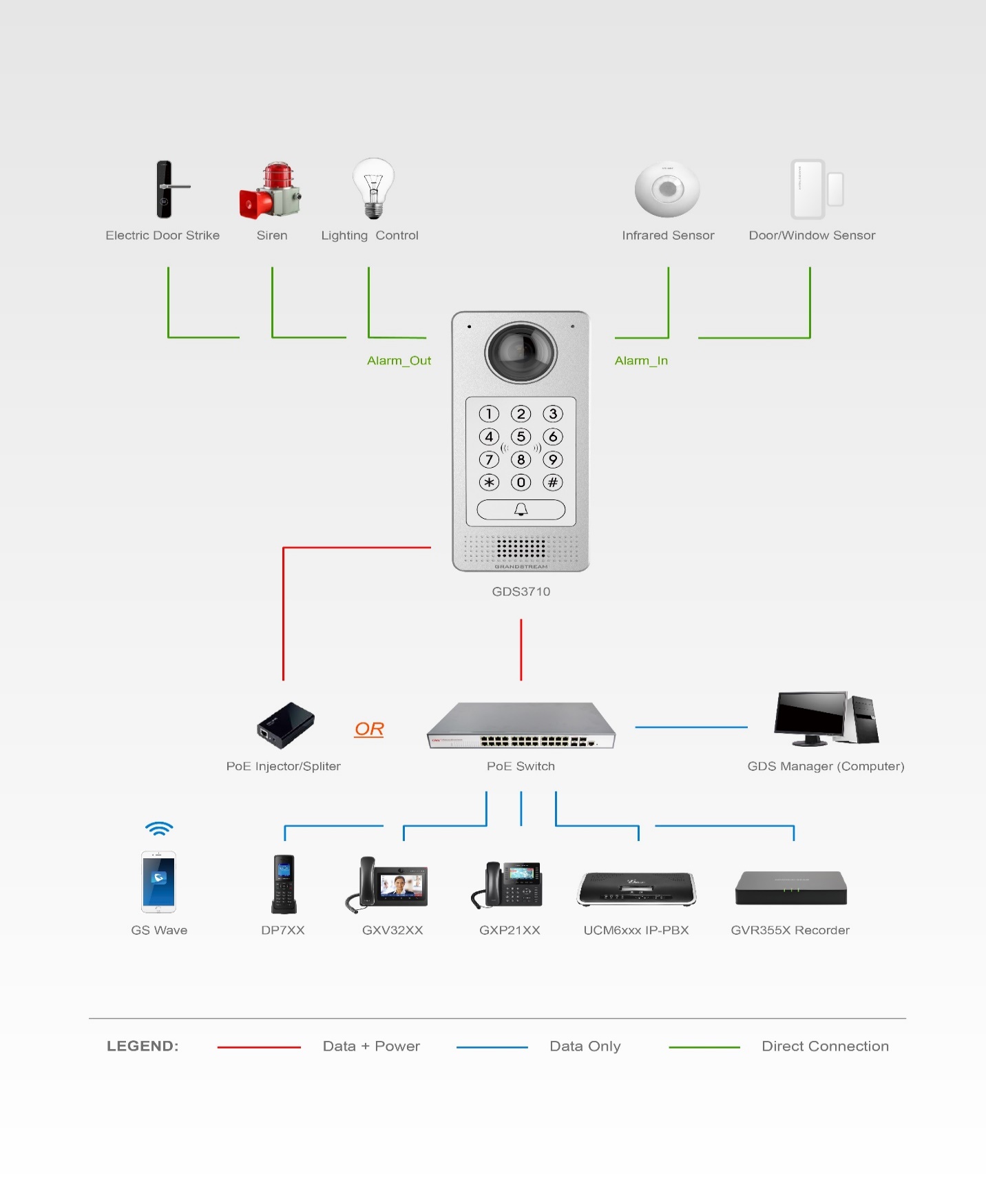
GDS3710 ALARM CONFIGURATION
The below diagram illustrates an example of peripheral connections for the GDS3710.
To configure the Alarm IN/OUT on the GDS3710, access the webGUI, after detecting the GDS3710 IP address using one of the methods previously mentioned, and log in as admin (the default user/pass for admin log in is admin/admin).
Navigate to “Alarm Config”, this tab contains four sub sections as shown below.
Alarm Schedule
This page specifies the configuration of Alarm Schedule.
Schedule must be in place before the alarm take the related action.
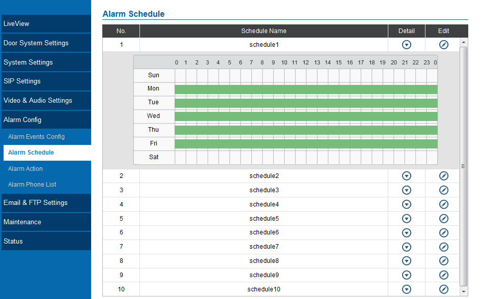
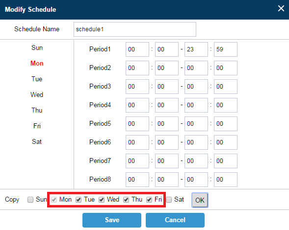
GDS3710 supports up to 10 alarm schedules to be configured, with time span specified by users. User can edit the alarm schedule by clicking ![]() button. Usually the 24 hours’ span is 00:00 ~ 23:59, which is 24 hours’ format.
button. Usually the 24 hours’ span is 00:00 ~ 23:59, which is 24 hours’ format.
Users can copy the configuration to different date during the schedule programming.
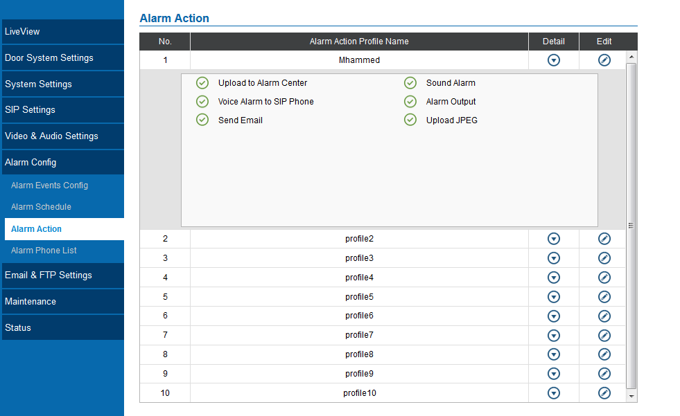
Alarm Action
This page specifies the configuration of Profile used by the Alarm Actions. A Profile is required before the Alarm Action can take effect.
User can edit the alarm action by clicking ![]() button, the following window will popup.
button, the following window will popup.
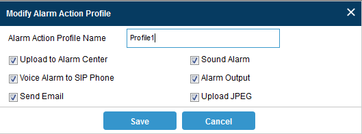
Table 1: Alarm Actions
Upload to Alarm Center | When checked, the alarm video will be transferred to Alarm Center. |
Voice Alarm to SIP | If the SIP server or the peer IP device is configured, check this will allow the event to trigger alarm SIP call to pre-configured number. |
Send Email | When checked, an email will be sent when the events are triggered to the pre-configured email account. |
Sound Alarm | When selected, alarm will be played from the GDS3710 Built-in Speaker. |
Alarm Output | An alarm will be sent to the Alarm Output interface if this option is checked. |
Upload JPEG | When checked, snapshots of the moment where the event is triggered will be uploaded to the FTP server. |
Alarm Phone List
This page allows user to configure the Alarm Phone List, which is phone numbers or extensions list that the GDS3710 will call out when event trigged (e.g.: doorbell pressed).
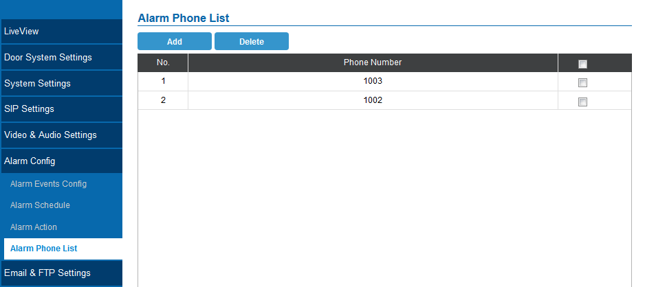
Add | Add new phone number to the alarm list. |
Delete | Delete a number from the phone alarm list. |
Once the event is triggered (Motion Detection, Door Bell Pressed…) the GDS3710 will call the first number, once time out is reached and no answer is returned from the first number, the GDS3710 will try the next number on the list and so on. Once the remote phone answers the call an alarm will be played to notify users that an event is triggered.
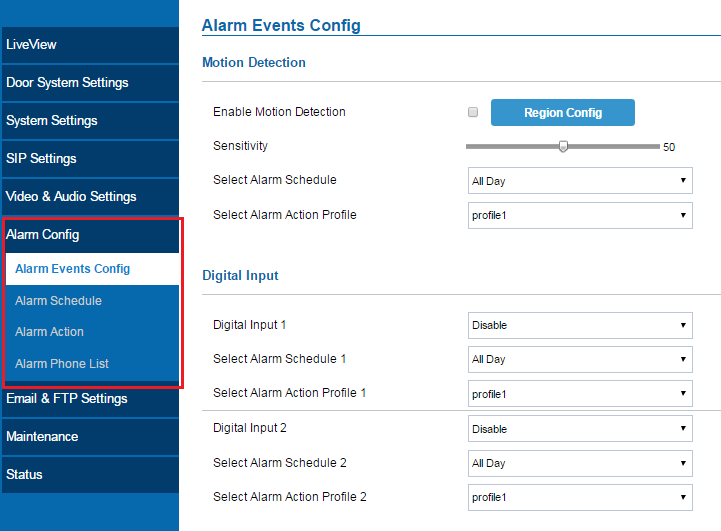
Alarm Events Config
This page allows users to configure GDS3710 events to trigger programmed actions within predefined schedule.
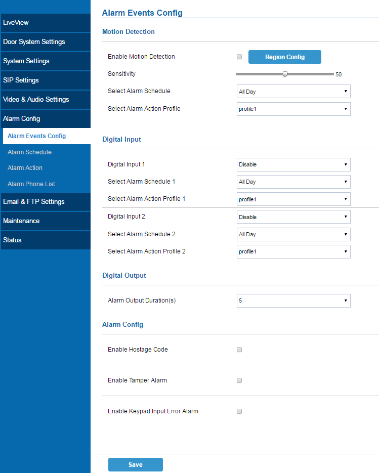
Alarm can be triggered either by motion detection or by GDS3710 input.
Motion Detection
Users can select a specific region to trigger the alarm using motion detection.
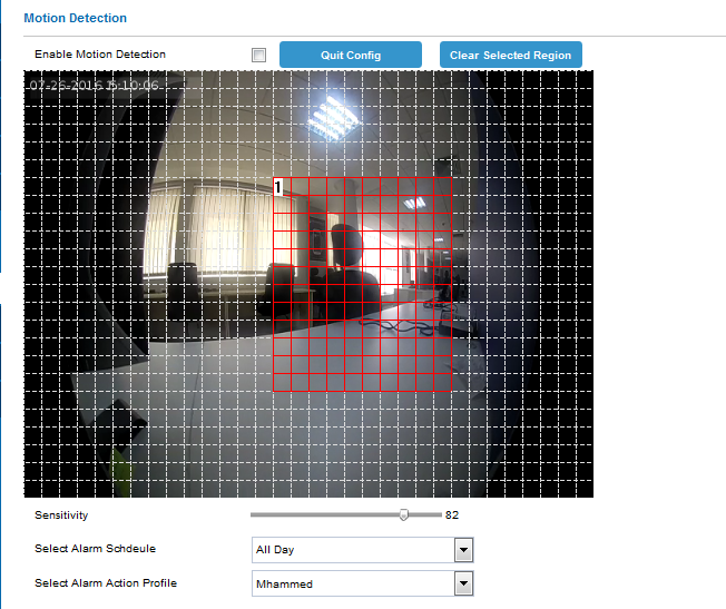
Table 3: Motion Detection
Enable Motion Detection | Click on the check box to enable Motion Detection. |
Region Config | Click to enter the Region Config menu. |
Quit Config | Click to exit the Region Config menu. |
Clear Selected Region | Select a zone on the screen then click on Clear to delete the region. |
Sensitivity | Region sensitivity (value between 0-100%). |
Select Alarm Schedule | Select the Schedule programmed. |
Select Alarm Action Profile | Select the programmed Alarm Action. |
Digital Input
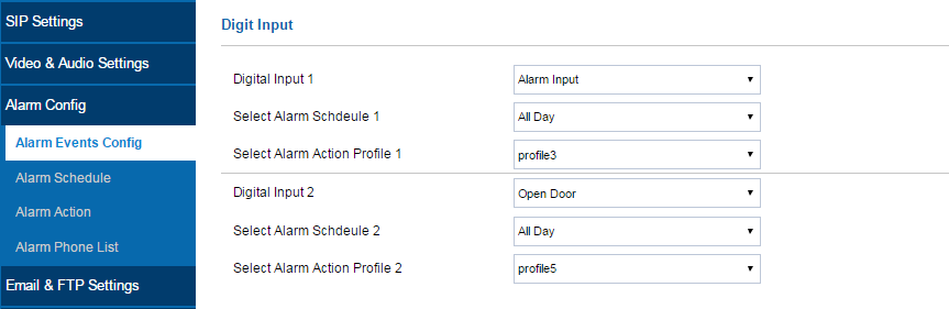
Table 4: Digital Input
Digital Input 1 | Select the Input method (alarm Input or Door Open). |
Select Alarm Schedule 1 | Select the predefined Schedule. |
Select Alarm Action Profile 1 | Select the predefined Alarm Action. |
Digital Input 2 | Select the Input method (alarm Input or Door Open). |
Select Alarm Schedule 2 | Select the predefined Schedule. |
Select Alarm Action Profile 2 | Select the predefined Alarm Action. |
Alarm Output
Alarm Output Duration(s) specifies how long the alarm output will take effect.
The valid range is 5 to 300 seconds.
Hostage Code
Hostage password can be used in a critical situation for instance a kidnaping or an emergency, users need to enter the following sequence to trigger the actions set for the Hostage Mode: “* HostagePassword #”.
Table 5: Hostage Code Alarm
Enable Hostage Password | Enable/Disable Hostage password mode. |
Hostage Code | Set the password for the hostage mode. |
Select Alarm Action Profile | Select the Alarm action to be taken when the hostage password is typed on the GDS3710 keypad. |
Tamper Alarm
Tamper alarm is anti-hack from Hardware level. When this option is checked, if the GDS3710 is removed from the installation board, it will generate the alarm actions configured. There is an embedded mechanism on the GDS3710 that allow it to sense when the it is removed.
Table 6: Tamper Alarm
Enable Tamper Alarm | When activating this mode, GDS3710 will keep alarming until the alarm is dismissed. |
Select alarm Action Profile | Select the type of alarms to be taken for the tamper alarm mode. |
Keypad Input Error Alarm
Table 7: Keypad Input Error Alarm
Enable Keypad Input Error Alarm | Enable/Disable the Input Error Alarm, GDS3710 will take alarm actions every 5 incorrect attempts. |
Select Alarm Profile | Select the Alarm action to be taken after 5 incorrect attempts. |