
INTRODUCTION
GDS37xx is an audio/video door access system, an innovative IP-based powerful door system. The GDS37xx was built for users looking for a strong audio/video facility access and security monitoring solution that can be deployed in environments of all sizes.
The tamper alarm is anti-hack from the Hardware level. When this option is checked, if the GDS37xx is removed from the installation board, it will trigger configured alarm actions. There is an embedded mechanism on the GDS37xx that allows it to detect when it is removed.
FUNCTIONALITY
In a situation where the GDSD37xx is being tampered with, it can generate an alarm to notify the user.
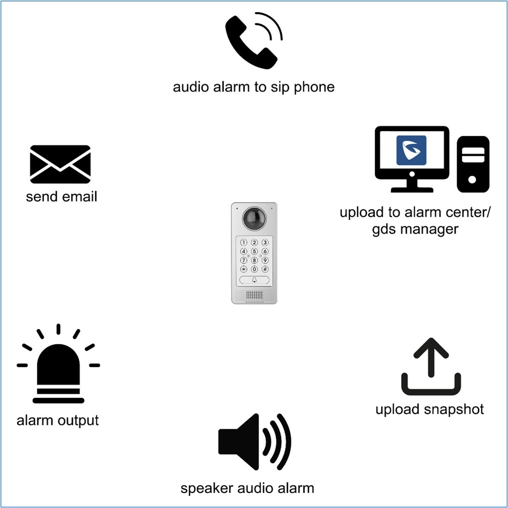
The GDS37XX alarm that can be triggered are:
- Upload to Alarm Center: If selected, the GDS Manager will pop up the alarm window and sound the alarm in the computer speaker.
- Audio Alarm to SIP Phone: If selected, GDS37xx will call a pre-configured (video or audio) phone and will play a sound alarm.
- Send Email: If selected, an email with a snapshot will be sent to the pre-configured email destination. (on GDS371x only)
- Audio Alarm: If selected, GDS37xx will play alarm audio using a built-in speaker.
- Alarm Output: If selected, the alarm will be sent to the equipment (for example Siren) connected to the Alarm Output interface.
- Upload Snapshot: If selected, snapshots at the moment where the event is triggered will be sent to a preconfigured destination e.g. FTP or email. (on GDS3710/GDS3712 only)
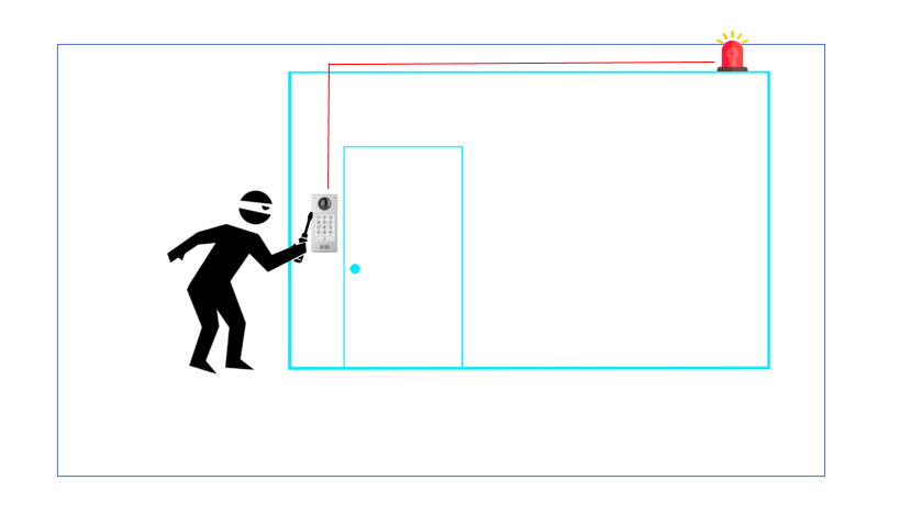
WIRING DIAGRAM
In this scenario, we assume that the GDS3710 is installed on a small warehouse at the front door and an alarm on the GXV IP phone along with a siren is set to alert in case of someone starts tampering with the GDS37xx.

INSTALLATION STEPS
The first step would be the hardware installation to properly use the Tamper Sensor feature.
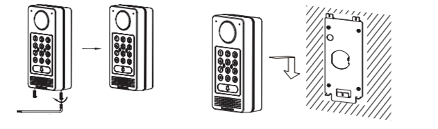
Step 1: Refer to the “drilling template” to drill holes at a targeted place on the wall then mount the installation bracket using the four screws and anchors provided (screwdriver not provided). Connect and tighten the “Ground” wire (if available) to the bracket ground marked with the printed icon.
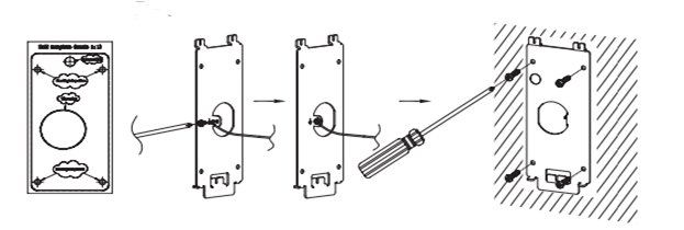
Step 2: Pull the Cat5e or Cat6 cable (not provided) through the rubber gasket selecting the correct size and the back cover panel piece, please refer to “GDS3710 WIRING TABLE” at the end of the QIG for Pin connections.

Step 3: Make sure the ”Back Cover Frame” is in place, and the wired back cover panel is good. Flush the back cover panel piece with the whole back surface of the device, and tighten it using the screws provided.
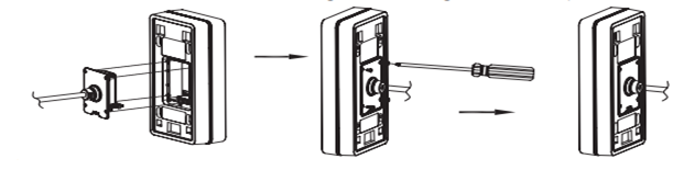
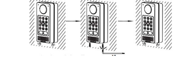
Step 4: Use the hex key provided to remove the two preinstalled anti-tamper screws. Carefully align the GDS37xx to the metal bracket on the wall, then press and pull the GDS37xx down to the right position.
Step 5: Install the two anti-tamper screws back using the hex key provided (do NOT over-tighten the screws). Cover the two screw holes on the bottom of the “Back Cover Frame” piece using the two silicon plugs provided. Final check and finish the installation.
GDS37XX WEB CONFIGURATION
Once the hardware steps are done, then we will proceed to Web Configuration as the following example:
- Register a SIP account,
- Configure alarm action profile,
- Add the remote phone to the Alarm phone list,
- Enable the tamper alarm.
Register a SIP Account
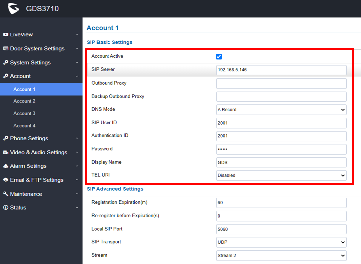
This page allows the administrator to configure the SIP account basic and advanced settings for each SIP account:
- Go to Account 🡪 Account 1
- Click on Account Active,
- Enter the SIP Server: configures the FQDN or IP of the SIP server from the VoIP service provider or local IPPBX.
- Enter the SIP extension in the SIP user ID field,
- Enter the SIP extension authentication ID in the authentication ID field,
- Enter the SIP extension password in the password field,
- Save the settings.
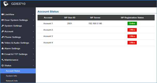
When the SIP account is registered, the SIP Registration status display will be Status 🡪 Account Status
Configure Alarm Action Profile
This part specifies the configuration of the Profile used by the Alarm Actions. A Profile is required before the Alarm Action can take effect.
To set an alarm action profile go to Alarm Settings 🡪 Alarm Action Settings:
- Select a profile and click on Edit,
- Name the Alarm action profile,
- Select the Action to trigger when the device detects tampering, then save.

Add the Remote Phone to The Alarm Phone List
The remote SIP phone or mobile phone needs to be added to the alarm phone list. The GDS37XX supports up to 10 alarm phones.
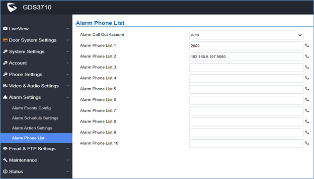
To add a phone, go to Alarm Settings 🡪 Alarm Phone List
- Alarm Call Out Account: select the SIP account to be used by the GDS37XX when alarm out is triggered.
- Alarm Phone List x: add or delete the number from the phone alarm list. (When an IP address is used then the port needs to be appended, for example, 192.168.5.197:5060)
Enable Tamper Alarm
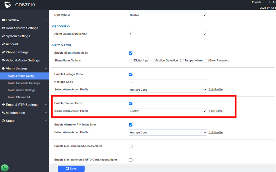
To enable the Tamper alarm feature and select the appropriate alarm action profile to use, head to Alarm Settings 🡪 Alarm Events Config, under Alarm config, and enable Tamper Alarm, then the configured profile must be chosen under Select Alarm Action Profile.
Tamper Alarm Test
To verify that the tamper alarm is working, try to remove the GDS37xx by tampering with the screws and the GDS37xx will show “Triggered” status on Tamper Sensor.
SUPPORTED DEVICES
The following table shows the supported products and the minimum firmware to use:
Product | Firmware |
GDS3702 | 1.0.1.16 |
| GDS3705 | 1.0.1.16 |
| GDS3710 | 1.0.7.23 |
| GDS3712 | 1.0.7.23 |