OVERVIEW
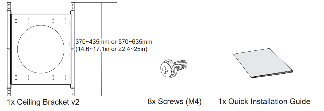
This guide provides instructions for using Ceiling Bracket v2 to assist in installation when the ceiling pad cannot support the weight of the GSC3506 v2. After installing the Ceiling Bracket v2, refer to the GSC3506 v2 Quick Installation Guide for additional instructions on how to mount it onto the bracket.
PACKAGE CONTENT
HARDWARE INSTALLATION
On the Ceiling Pad
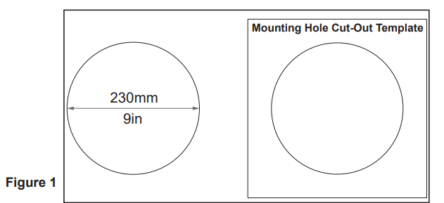
- Drill a round hole with a diameter of 230mm or use the Mounting Hole Cut-Out Template (included in the GSC3506 v2 Package).
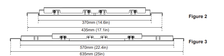
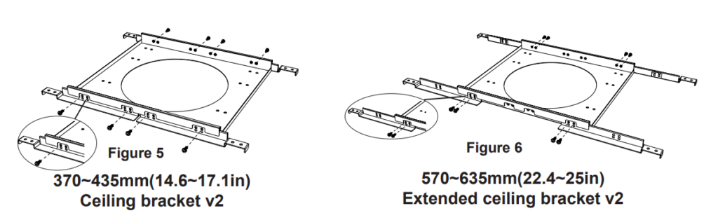
2. Adjust the length of the Ceiling Bracket to either 370~435mm (14.6~17.1in) or 570~635mm (22.4~25in) to match the ceiling pad size, as shown in Figure 2, and Figure 3
3. Fix the ceiling bracket telescopic length by screwing eight screws (M4) provided into the designated holes, the position of the screws depends on whether the ceiling bracket is extended or not as shown in Figure 5 and Figure 6.
4. Position the ceiling bracket onto the ceiling in a way that the hole on the bracket aligns exactly with the measured hole on the ceiling pad as shown in the illustration at Figure 7 and 8, based on the Cut-out template diameter determined in Figure 1.
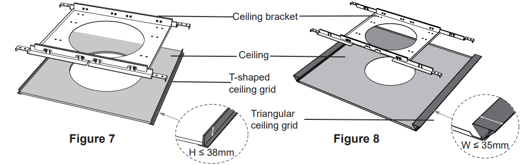
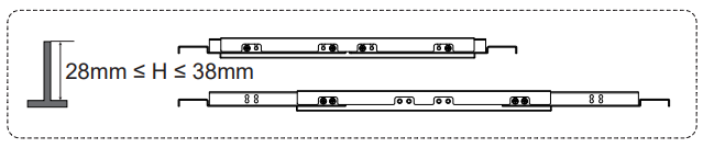
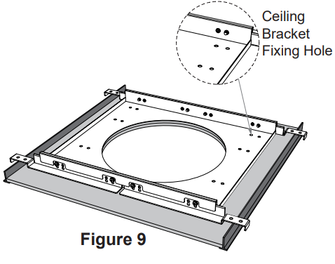
5. Align the hooks with the T-shaped or triangular ceiling grid. For better security, you can fix the ceiling bracket on the ceiling pad using screws in the designated holes illustrated as shown in Figure 9.
On the Ceiling Beam
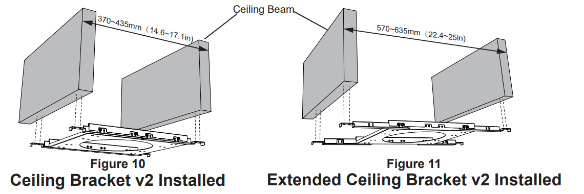
Install the ceiling bracket on the ceiling beam by fixing the bracket onto the ceiling grid holes using screws as shown in Figure 10, and its extended version in Figure 11.