


Introduction
The GSC356X-FM Flush-Mount Kit is an optional mounting accessory designed for the Grandstream GSC3560 and GSC3565 HD Intercom and Facility Control Stations. It enables a clean, professional in-wall installation by recessing the device into the wall, reducing its protrusion, and enhancing the overall appearance of the deployment. The kit includes the flush-mount enclosure, mounting hardware, installation template, and cable management accessories required for secure installation. It is ideal for environments such as office buildings, residential complexes, schools, healthcare facilities, and commercial premises where a sleek and integrated mounting solution is preferred.
Package Content
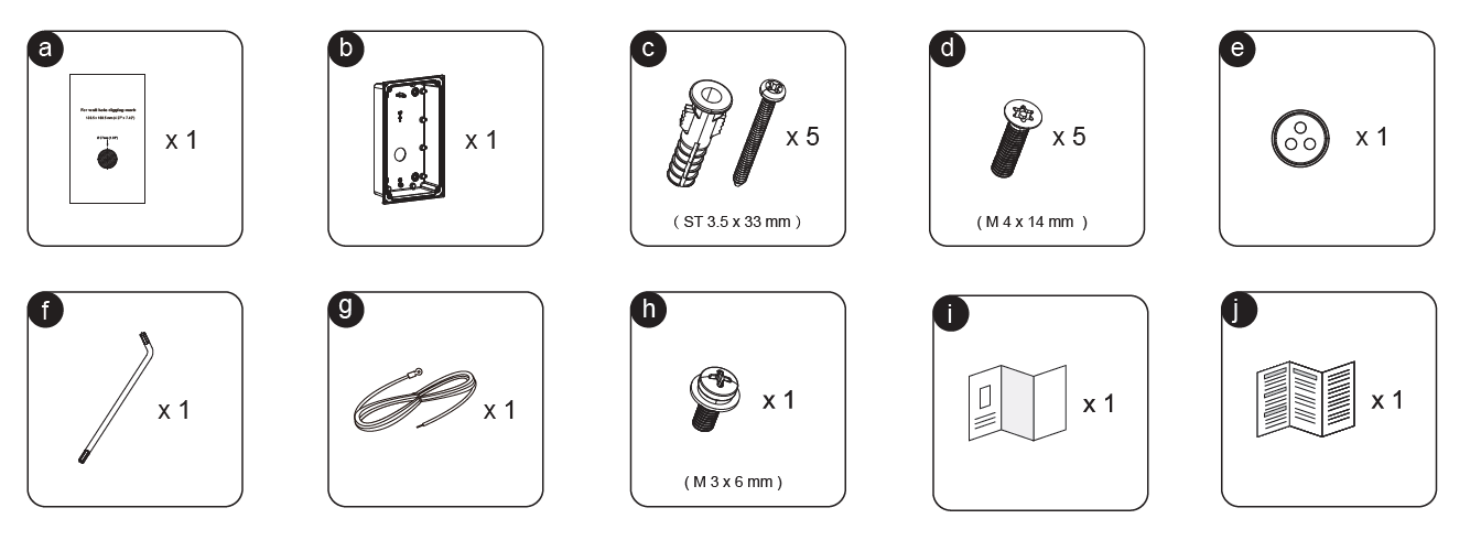
| Letter | Component | Quantity | Description |
|---|---|---|---|
| a | Wall Cutout Template | 1 | Template used to mark the wall opening and drilling positions for flush mounting. |
| b | Flush-Mount Back Box | 1 | Main enclosure that is recessed into the wall and houses the GSC356X device. |
| c | ST 3.5 × 33 mm Screws with Anchors | 5 | Wall-mounting screws and anchors used to secure the back box to the wall. |
| d | M4 × 14 mm Screws | 5 | Screws used for attaching the mounting components and securing the device assembly. |
| e | Cable Grommet | 1 | Protective grommet used to route cables through the back box while protecting them from damage. |
| f | L-Shaped Hex Key | 1 | Tool provided for tightening and securing mounting hardware during installation. |
| g | Cable Tie | 1 | Used for cable organization and strain relief inside the flush-mount enclosure. |
| h | M3 × 6 mm Screw | 1 | Special retaining screw used to secure internal mounting components. |
| i | Quick Installation Guide (QIG) | 1 | Installation guide containing mounting instructions and setup information. |
| j | Regulatory & Safety Information | 1 | Documentation containing regulatory compliance, warranty, and safety information. |
Flush Mount Installation
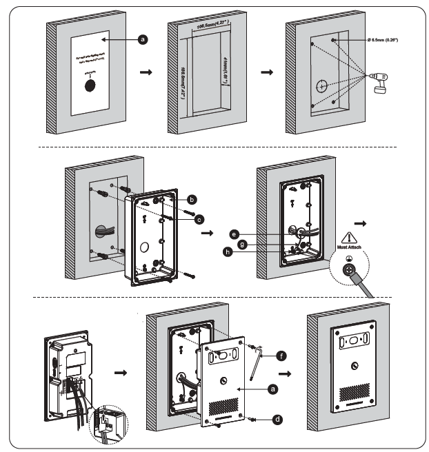
Follow the steps below to install the GSC356X-FM Flush-Mount Kit:
Mark and Prepare the Wall Opening
- Use the supplied wall cutout template (a) to mark the mounting area on the wall.
- Cut an opening measuring 108.5 mm × 188.5 mm (4.27″ × 7.42″).
- Drill the required mounting holes (Ø 6.5 mm) according to the template.
Install the Flush-Mount Back Box
- Insert the wall anchors and route the network and power cables through the wall opening.
- Position the flush-mount back box (b) inside the opening.
- Secure the back box to the wall using the supplied mounting screws and anchors (c).
Secure the Cable Management Components
- Install the cable grommet (e) into the designated opening.
- Route the cables through the grommet and organize them using the cable tie (g).
- Secure the cable management assembly with the M3 × 6 mm screw (h). This step is mandatory to ensure proper cable retention.
Connect the GSC356X Device
- Connect the required cables to the rear ports of the GSC3560/GSC3565.
- Carefully place the device into the flush-mount back box.
Attach the Front Panel
- Align the device with the installed back box.
- Secure the assembly using the M4 × 14 mm screws (d).
- Tighten the security screw using the supplied hex key (f).
Verify Installation
- Confirm that the device is firmly secured and sits flush with the wall surface.
- Power on the device and verify normal operation.
After following the above steps, the GSC356X Door intercom device will be securely recessed into the wall, providing a clean, professional, and low-profile installation.