Introduction
The GSC3518HS is a high definition multicast talk-back horn speaker that allows public spaces, large offices, school playgrounds, hospitals, parks and more verticals to build powerful outdoor announcement solutions that expand security and communication. This robust SIP speaker offers crystal clear HD audio functionality with a high-fidelity 50-Watt speaker and supports IP66 dust and water resistance. The stainless steel packaging is sturdy and durable and can be used in extreme weather conditions.The GSC3518HS supports POE++ input and POE+ output, catering to another device cascading scenarios. Users can easily sculpt a state-of-the-art security and PA announcement solution. Thanks to its modern industrial design and rich features, the GSC3518HS is an ideal SIP talk-back horn speaker for any setting.
Package Content
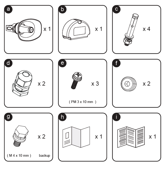
Label | Item | Quantity | Description |
a | Speaker Main Unit | ×1 | Main GSC3518HS outdoor speaker body with adjustable mounting arm. |
b | Junction Box Cover | ×1 | Protective housing for the rear cable connections. |
c | Expansion Bolts | ×4 | Used for mounting the speaker bracket securely to a wall or ceiling. |
d | Cable Glands | ×2 | Waterproof cable connectors to seal and protect input cables. |
e | Mounting Screws | ×3 | PM 3 × 10 mm screws for securing the junction box cover. |
f | Rubber Gaskets | ×2 | Replaceable seals used to maintain waterproof performance. |
g | Backup Bolts | ×2 | M4 × 10 mm bolts for bracket adjustment and backup locking. |
h | Quick Installation Guide | ×1 | Printed guide for installation steps. |
i | Regulatory Paper | ×1 | Complete Regulatory information. |
Back Cover Ports
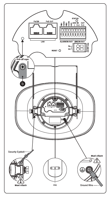
The back panel of the GSC3518HS contains all primary wiring ports, grounding points, and mounting connections.
Proper wiring and grounding are essential to ensure safety, waterproof sealing, and reliable performance.
Main Connectors and Terminals
Port / Label | Description |
PoE IN (LAN) | RJ45 network port supporting Power over Ethernet (PoE). Provides both data and power to the speaker through a PoE switch or injector (IEEE 802.3af/at/bt). |
PoE OUT | RJ45 passthrough port used to supply PoE power and data to another device, such as an additional IP speaker or camera. |
ALARM IN/OUT (IN1, IN2, GND, NO, COM) | Terminal block for external alarm integration. IN1/IN2 are digital inputs for sensors or triggers; GND is the common ground; NO/COM form a relay output for controlling external alarms or devices. |
LINE IN/OUT (IN+/–, OUT+/–, GND) | Balanced audio input/output interface. Allows connection to external microphones, amplifiers, or powered speakers for extended audio coverage. |
DC 24–48V | Power input terminal for direct DC power supply (24V–48V) when PoE is not used. Polarity-sensitive. |
Ground Wire Terminal | Dedicated grounding point. Must be connected to an earth ground to prevent electrical surges or static damage. |
Security Eyebolt | Anchor point for a safety cable or chain to prevent the device from falling if the mounting structure fails. |
Anti-off Rope | Safety securing screw point used to temporarily hold the device during installation or maintenance. |
MIC | Built-in microphone port for audio capture, monitoring, or two-way communication functions. |
Ceiling Mount
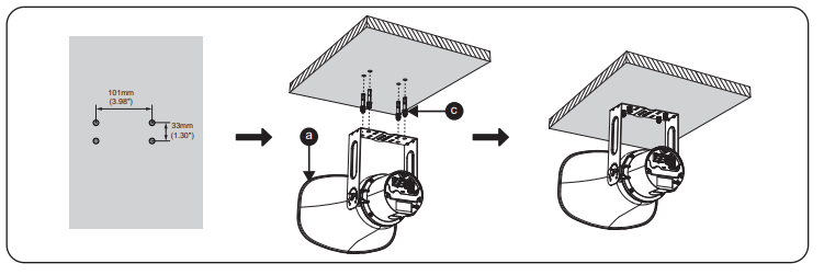
The GSC3518HS can be mounted on a ceiling or any flat overhead surface using the included expansion bolts.
This method ensures a stable, downward-facing audio projection, ideal for wide outdoor areas.
Installation Steps
- Mark the Drill Points
- Use the bracket of the speaker (a) as a reference or follow the illustrated mounting pattern.
- Mark three holes on the ceiling in the exact layout:
- Horizontal spacing: 101 mm (3.98”)
- Vertical spacing: 33 mm (1.30”)
- Drill and Prepare the Mounting Surface
- Drill holes at the marked positions.
- Insert the expansion bolts (c) into each hole to secure the mounting base.
- Attach the Speaker Bracket
- Hold the speaker unit (a) with its bracket aligned to the drilled holes.
- Fasten the bracket using the installed expansion bolts (c).
- Ensure the bracket is fully tightened and the speaker hangs securely.
- Adjust Orientation
- After mounting, slightly adjust the angle of the speaker to direct sound output as desired.
- Make sure all bolts are firmly secured to prevent vibration or misalignment.
Pole Mount
The GSC3518HS can also be mounted onto a vertical or horizontal pole using metal straps (not included in the package).
This installation method is ideal for outdoor environments such as parking lots, campuses, or street areas where wall mounting is not suitable.
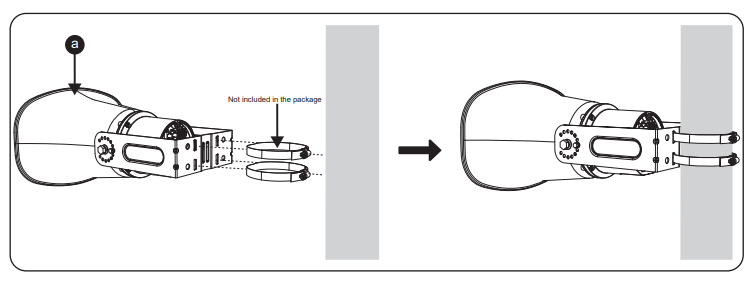
Installation Steps
- Prepare the Speaker Assembly
- Use the speaker unit (a) with its attached mounting bracket.
- Position the speaker bracket against the mounting pole.
- Attach the Metal Straps
- Insert two metal hose clamps or stainless steel straps (not included in the package) through the mounting slots on the bracket.
- Wrap each strap tightly around the pole and fasten securely using a screwdriver or wrench.
- Ensure both straps are parallel and firmly tightened to prevent movement.
- Adjust the Speaker Orientation
- Once attached, adjust the tilt or rotation of the speaker (a) for optimal sound direction.
- Confirm that all fasteners are tight and the bracket does not slide along the pole.
- Check Cable Routing
- Guide all cables neatly through the mounting bracket to the back of the speaker.
- Make sure cables are not twisted or pinched between the pole and the bracket.
Installing The Speaker Support
This step involves connecting the cable glands and securing the junction box cover before final tightening of the speaker’s bracket position.
Proper sealing and bolt alignment ensure both waterproof integrity and stable speaker support.
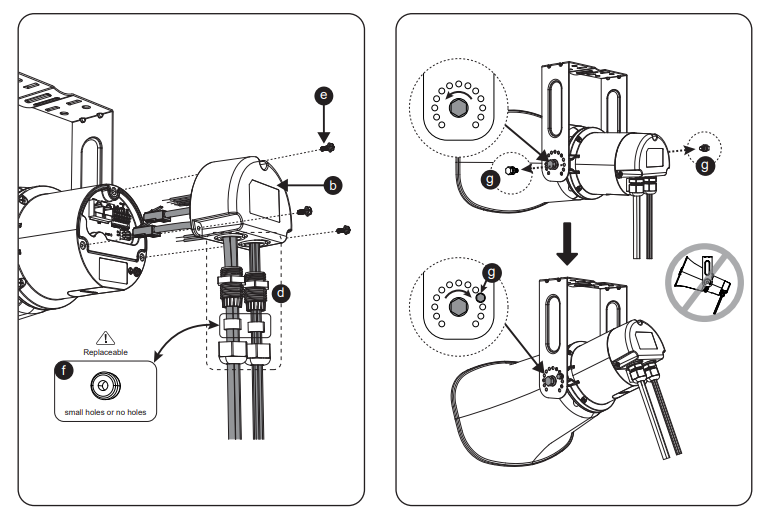
Installation Steps
- Connect the Cables
- Insert all power, network, and audio cables through the cable glands (d).
- Tighten the glands firmly to create a waterproof seal.
- Connect the cables to their respective ports inside the back cover (refer to the connection layout in Section 2).
- Attach the Junction Box Cover
- Place the junction box cover (b) onto the back housing, aligning the screw holes.
- Fasten it using the PM 3 × 10 mm screws (e) to secure the cover in place.
- Make sure the cover sits evenly and that all cable glands are facing downward.
- Replace Rubber Gaskets (if required)
- If the rubber gaskets (f) are worn, replace them with the included spares.
- Ensure the gasket surfaces are clean and fully pressed to maintain the waterproof seal.
- Secure the Speaker Bracket Angle
- Adjust the speaker’s tilt angle to the desired direction.
- Use the M4 × 10 mm bolts (g) to tighten the side pivot points on both sides of the bracket.
- Confirm both bolts are symmetrically tightened and the angle is locked.
- Final Check
- Verify that the junction box cover (b) and cable glands (d) are fully tightened.
- Ensure the speaker is stable, firmly mounted, and properly grounded.
- The bracket must not be over-tilted, refer to the illustration for correct alignment.
Accessing the Configuration Interface
Connecting With MAC Address
A computer connected to the same network as the GSC3518HS can discover and access its configuration interface using its MAC address :
- Locate the MAC address on the MAC tag of the unit, which is on the underside
of the device, or on the package. - From a computer connected to the same network as the GSC3518HS, type in the following address using the GSC3518HS’s MAC address on your browser: http://gsc_<mac>.local
Example: if a GSC3518HS has the MAC address C0:74:AD:11:22:33, this unit can be accessed by typing http://gsc_c074ad112233.local on the browser.
Connecting Using GS Search
A computer connected to the same network as the GSC3518HS can launch the GS Search App, and view the assigned IP address of the unit, then use that IP address in a local web browser to access the WebUI configuration Interface, Download the GS Search tool from the following link.
Example: the discovered IP address was : 192.168.6.15, the unit can be accessed by typing: http://192.168.6.15