The GDS3725, GDS3726, and GDS3726Q are IP Video Door Stations that also serve as high-definition IP surveillance cameras and IP intercoms, providing robust facility access control and security monitoring for buildings of all sizes. These advanced IP video door systems feature a 152-degree wide-angle lens for wall-to-wall coverage, AI ISP intelligent image processing, a built-in IC & ID card reader, and an NFC chip. They include two microphones and one speaker for full-duplex intercom functionality and offer alarm-in and alarm-out support for integration with existing security systems.
The GDS3726Q offers the same core functionality and features as the GDS3726, while providing four independent ringing buttons instead of a single ringing button. This makes the GDS3726Q particularly suitable for installations where multiple users, offices, apartments, or departments require individual calling options from a single door station.
The devices are fully manageable through Grandstream’s free GDS Manager utility, which allows control of ID and IC card data, video feeds, and system configurations. A free mobile app is also available, offering user-friendly access control management, remote door unlocking, and multi-method door access.
Equipped with a powerful AI Image Sensor Processor and advanced image algorithms, the GDS3725, GDS3726, and GDS3726Q deliver 1080p Full HD video with clear visibility even under extremely low-light conditions—up to 3 meters from the installation point. They support PoE, include white LED fill lights, motion detection, stay detection, and provide expandable interfaces such as DI/DO/RS485 for further integration.
Combined with Grandstream’s GSC357X Control Stations, GXV video phones, GS-Wave mobile app, and GNS network storage, the GDS3725, GDS3726, and GDS3726Q provide a complete end-to-end solution for access control, video intercom, and security recording.
Precautions:
Do not attempt to disassemble or modify the device.
Do not expose this device to temperatures outside the range of -30 °C to 60 °C for operating and -30°C to 70°C for storage.
Do not expose this device to environments outside of the following humidity range: 10-90% RH (non-condensing).
Do not power cycle the device during system boot-up or firmware upgrade. You may corrupt firmware images and cause the unit to malfunction.
Package Content
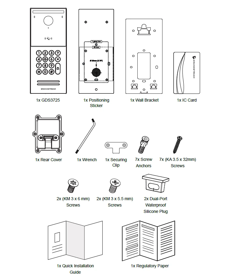
GDS3725
1 x GDS3725.
1 x Positioning Sticker.
1 x Wall Bracket.
1 x IC Card.
1 x Rear Cover.
1 x Wrench.
1 x Securing Clip.
7 x Screw Anchors.
7 x (ST 3.5 x 32mm) Screws.
2 x (M 3 x 6mm) Screws.
2 x (M 3 x 5.5mm) Screws.
2 x Dual-Port Waterproof Silicone Plug.
1 x Quick Installation Guide.
1 x Regulatory Paper.
GDS3725 Package Content
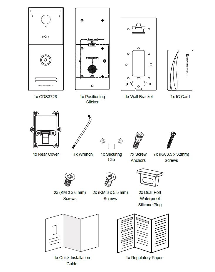
GDS3726
1 x GDS3726.
1 x Positioning Sticker.
1 x Wall Bracket.
1 x IC Card.
1 x Rear Cover.
1 x Wrench.
1 x Securing Clip.
7 x Screw Anchors.
7 x (ST 3.5 x 32mm) Screws.
2 x (M 3 x 6mm) Screws.
2 x (M 3 x 5.5mm) Screws.
2 x Dual-Port Waterproof Silicone Plug.
1 x Quick Installation Guide.
1 x Regulatory Paper.
GDS3726 Package Content
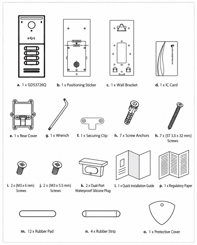
GDS3726Q
1 x GDS3726Q.
1 x Positioning Sticker.
1 x Wall Bracket.
1 x IC Card.
1 x Rear Cover.
1 x Wrench.
1 x Securing Clip.
12 x Rubber Pad
7 x Screw Anchors.
7 x (ST 3.5 x 32mm) Screws.
2 x (M 3 x 6mm) Screws.
2 x (M 3 x 5.5mm) Screws.
2 x Dual-Port Waterproof Silicone Plug.
1 x Quick Installation Guide.
1 x Regulatory Paper.
4 x Rubber Strip
1 x Protective Cover
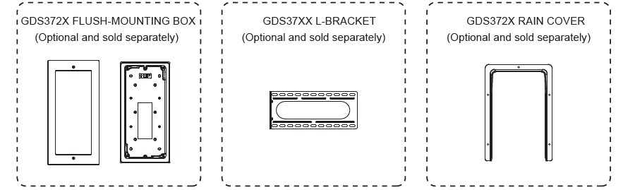
In addition to the items included in the package, the following optional accessories are available separately and may be required for specific wall-mounting or in-wall installation configurations.
Accessory
Description
Availability
GDS372X Flush-Mounting Box
Flush-mounting box for in-wall installation of the GDS372X.
Optional; sold separately
GDS37XX L-Bracket
L-bracket for wall-mounting installation of the GDS37XX series.
Optional; sold separately
GDS372X Rain Cover
Protective rain cover for outdoor wall-mounted installation of the GDS372X.
Optional; sold separately
Note
Check the package before installation. If you find anything missing, contact your system administrator.
Description of the GDS3725/GDS3726/GDS3726Q
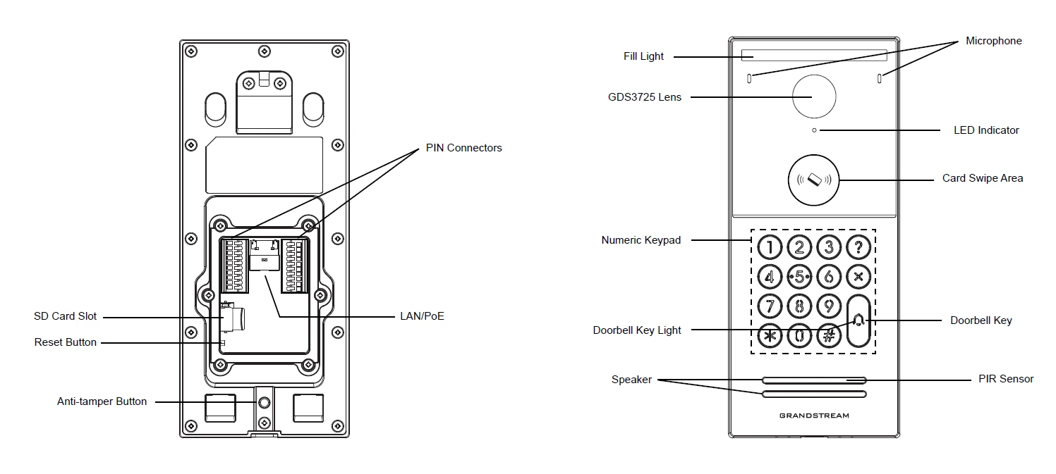
The figure below shows a description of the back and front views of the GDS3725 IP Video Door Station:
GDS3725 Front and Back View
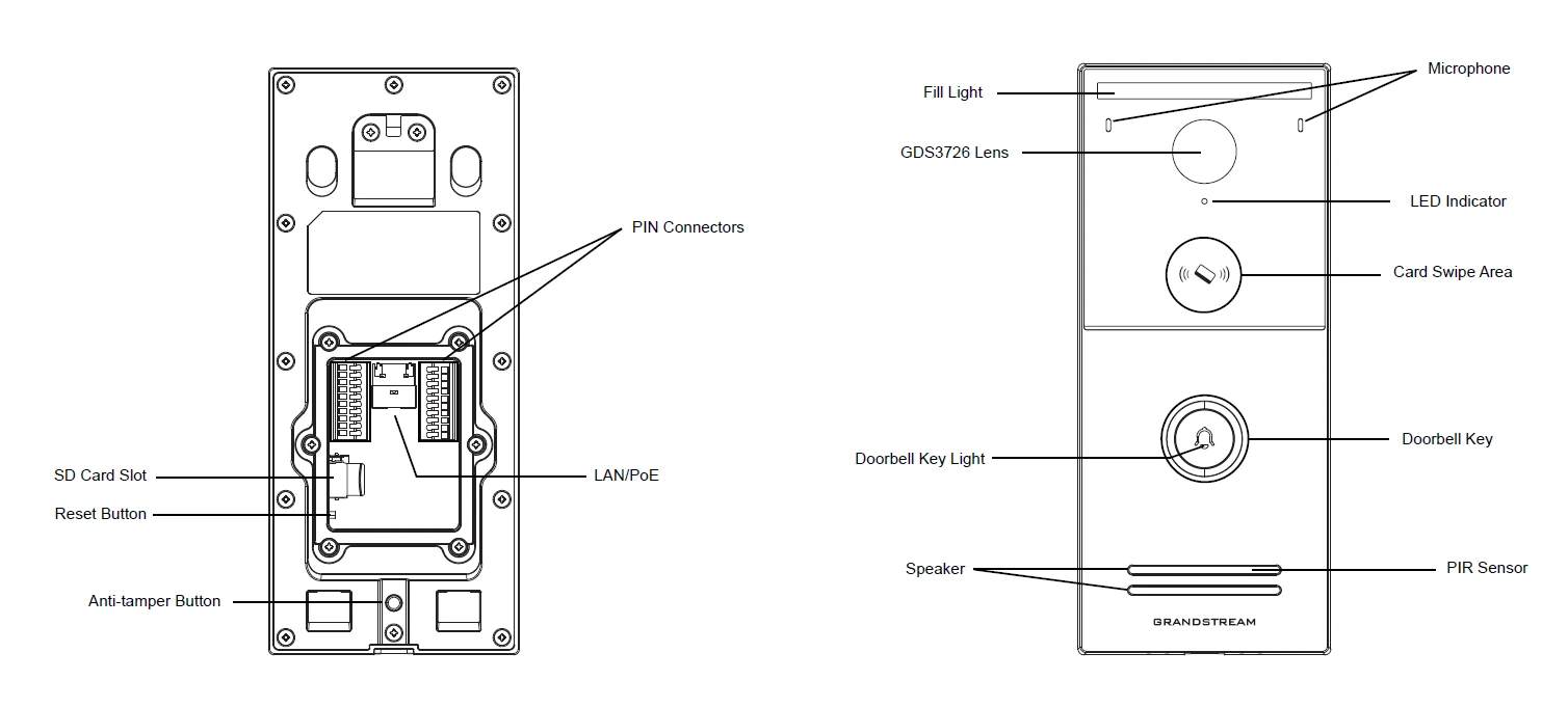
The figure below shows a description of the back and front views of the GDS3726 IP Video Door Station:
GDS3726 Front and Back View
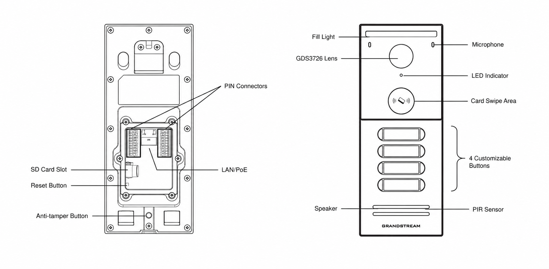
The figure below shows a description of the back and front views of the GDS3726 IP Video Smart Door Station:
GDS3726Q Front and Back View
GDS3725/GDS3726/GDS3726Q Wall Mount Installation
This section provides detailed instructions for installing the GDS3725/GDS3726 IP Video Door system on a wall using one of the following methods:
With a 1-gang box
With an 86 box
Direct wall mount (no box)
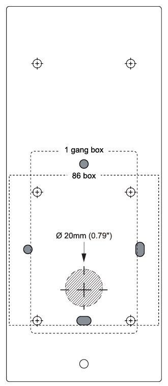
A positioning sticker is included in the package to ensure accurate and aligned mounting across all installation types.
Please follow these steps carefully to ensure a weather-protected and tamper-resistant installation:
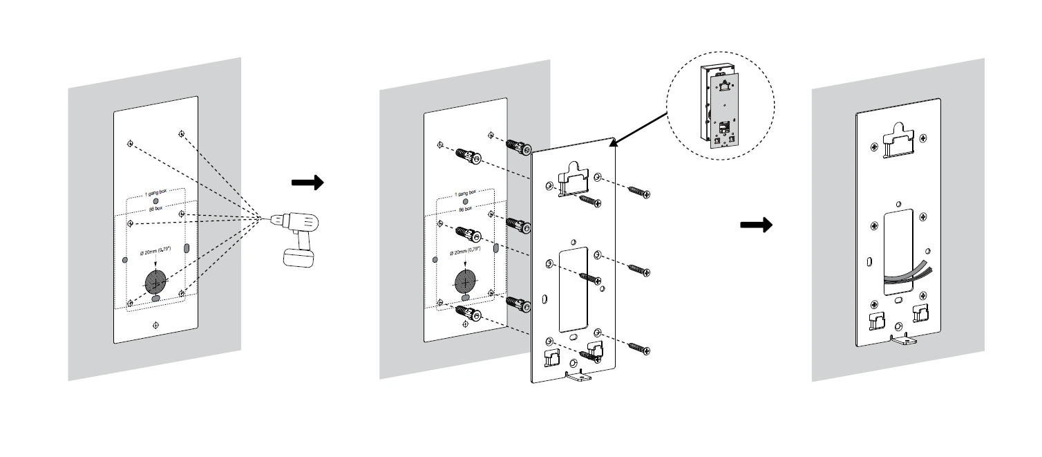
Place the provided positioning sticker on the wall at the desired mounting height.
Using the markings on the sticker as a guide, drill holes at the indicated positions.
Note
Drill patterns may vary depending on the selected installation method (1-gang box, 86 box, or direct wall mount).
Insert the supplied screw anchors into the holes.
Secure the wall-mounted bracket using the included KA 3.5 × 32mm self-tapping screws.
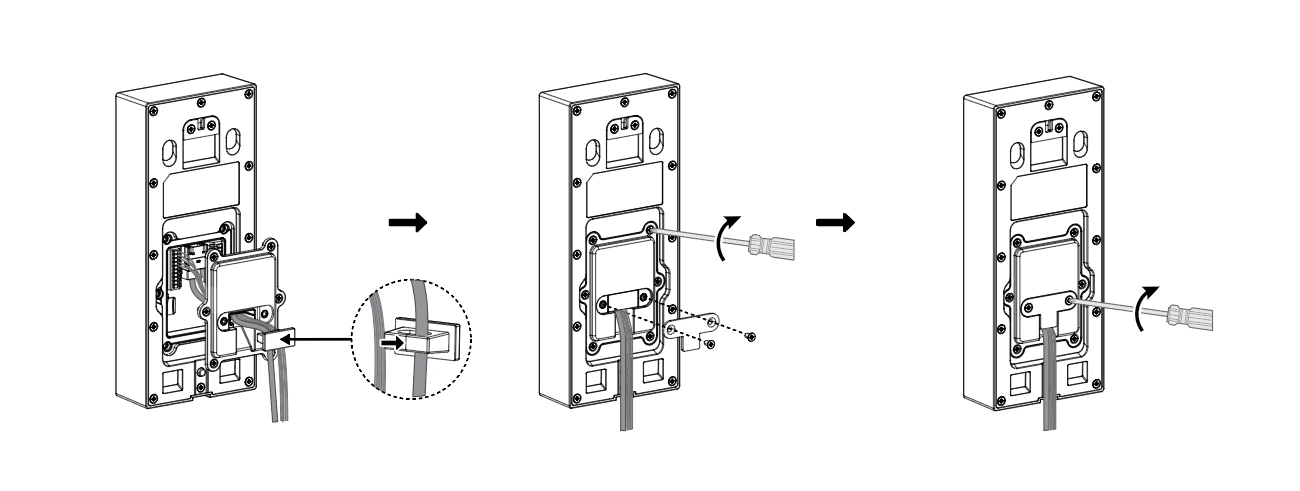
Route the necessary cables (power, network, door strike, etc.) through the center opening of the bracket.
Insert the waterproof silicone port plug into the cable exit area at the bottom of the rear cover to protect and organize the cables.
Place the rear cover onto the bracket, aligning it with the screw holes.
Secure the rear cover by placing the securing clip on top of it.
Fix the securing clip using the included KM 3 × 5.5mm screws.
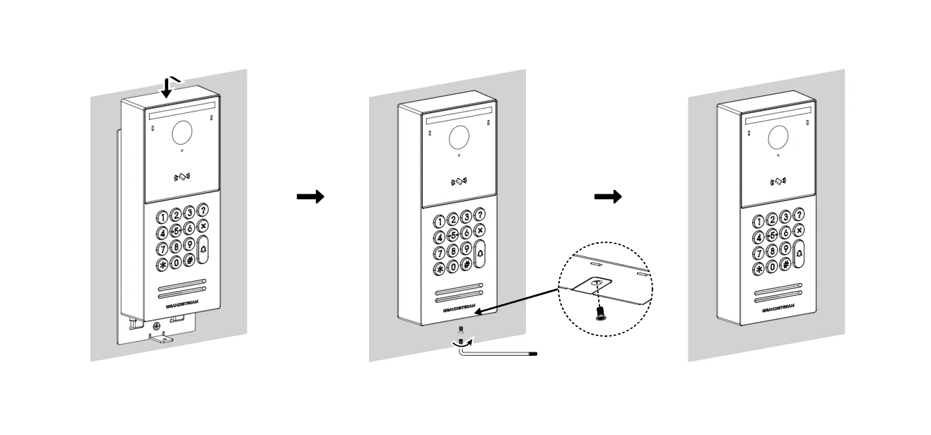
Place the device onto the wall-mounted bracket.
Use a wrench to tighten the KM 3 × 6mm screw, securing the door station to the bracket.
Powering the GDS3725/GDS3726/GDS3726Q
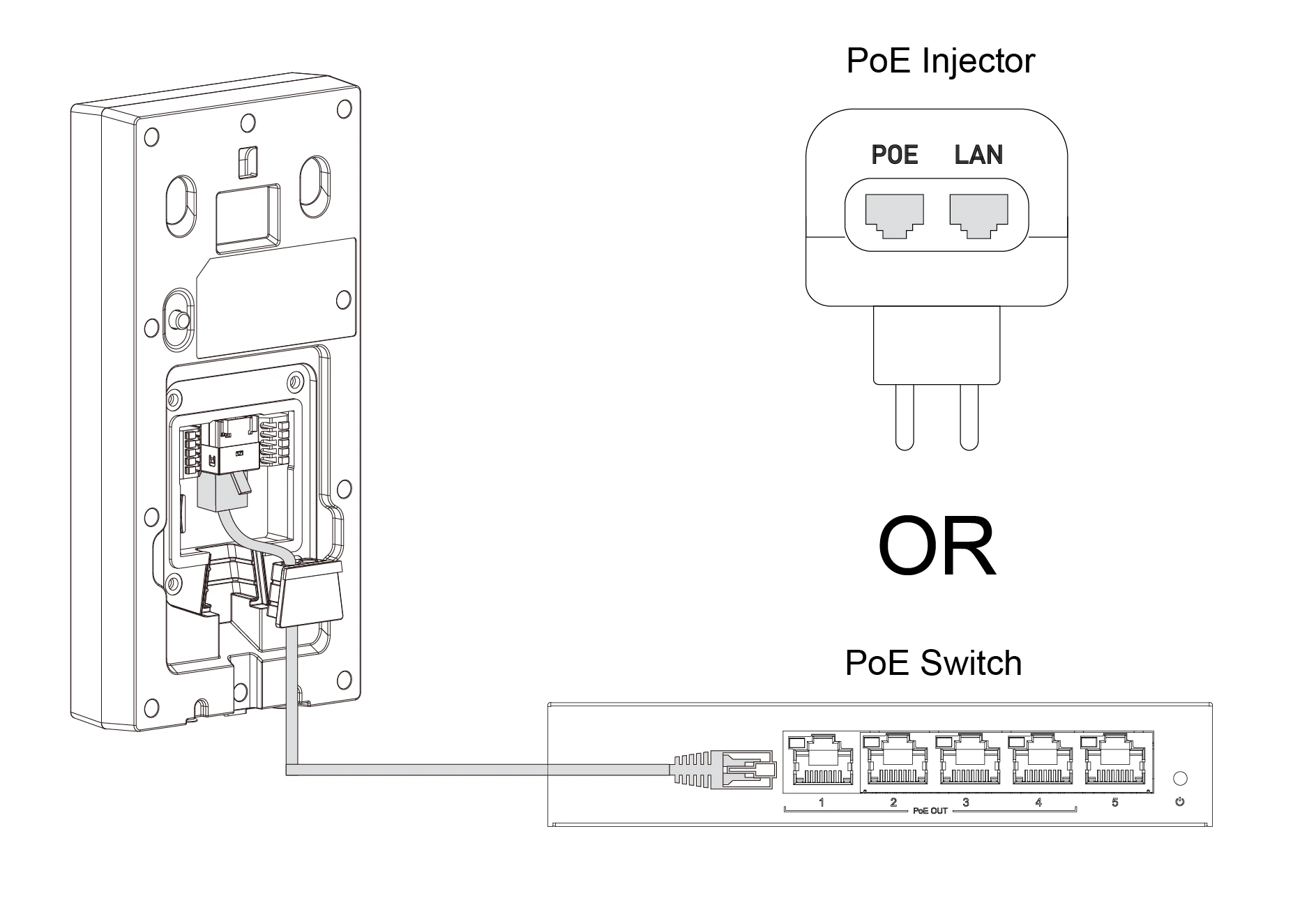
The GDS3725/GDS3726/GDS3726Q IP Video Door Station can be powered using PoE or PSU:
Using PoE (Suggested)
Connect the other end of the RJ45 cable to the PoE switch.
A PoE injector can be used if a PoE switch is not available.
Powering the GDS3725GDS3726GDS3726Q Using PoE
Using Power Supply Unit (Not Provided)
Connect the other end of the RJ45 cable to a network switch or router.
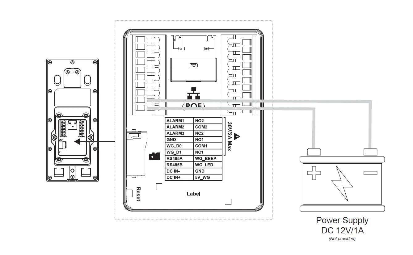
Connect a DC 12V power source via the related cable to the correct pins of the GDS3725/GDS3726/GDS3726Q.
Powering the GDS3725GDS3726GDS3726Q Using Power Supply
Monitored Angles
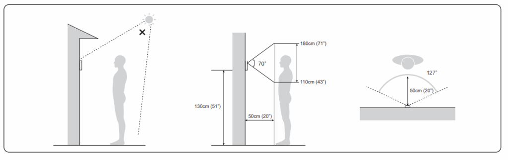
To ensure optimal video coverage and intercom usability:
Mount the camera lens at 130 cm (51″) height from the ground.
Ideal face detection height is approximately 110 cm (43″).
Maintain a clear front space of at least 50 cm (20″).
The device provides a 127° horizontal and 70° vertical field of view, covering a wide area effectively.
Avoid direct exposure to strong light sources (e.g., sunlight) to prevent image distortion.
GDS3725/GDS3726/GDS3726Q Wiring Connection
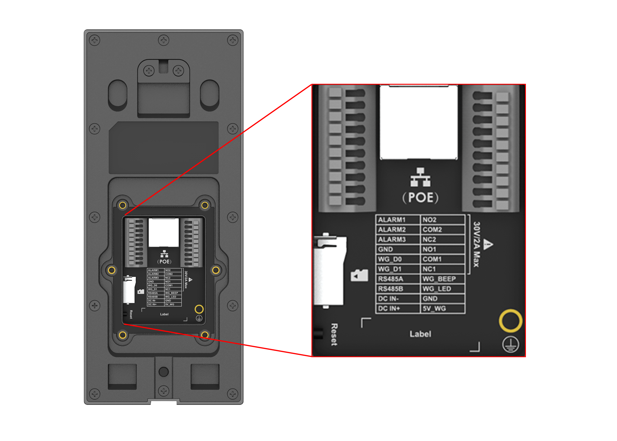
The GDS3725/GDS3726/GDS3726Q provides a terminal block interface for power, relay control, alarm integration, RS-485 communication, and Wiegand input/output. Below is a detailed explanation of each pin and its function:
GDS3725GDS3726GDS3726Q Wiring Connection
Connector
Function
Note
Network Port(PoE)
Ethernet and PoE Supply
Single 10/100Mbps network port, supports 802.3 af PoE power supply.
ALARM1
Alarm Input 1
Input for external devices (e.g., door contacts, sensors, or exit buttons).
ALARM2
Alarm Input 2
ALARM3
Alarm Input 3
GND
Alarm Ground
Common ground reference for alarm inputs.
RS485A
RS485 Communication (+)
Positive line for RS485 differential signal.
RS485B
RS485 Communication (-)
Negative line for RS485 differential signal.
DC IN-
Power Supply (-)
Negative terminal for DC power input.
DC IN+
Power Supply (+)
Positive terminal for DC power input. Supports a wide voltage range DC 9V–36V.
NO2
Relay Output2
For “Fail Secure” (Locked when Power Lost) Strike, connect COM2 & NO2.
For “FailSafe” (Open when No Power) Magnetic Lock, connect COM2 & NC2.
Relay: 30VDC/2A.
COM2
NC2
NO1
Relay Output1
For “Fail Secure” (Locked when Power Lost) Strike, connect COM1 & NO1.
For “FailSafe” (Open when No Power) Magnetic Lock, connect COM1 & NC1.
Relay: 30VDC/2A.
COM1
NC1
WG_BEEP
Wiegand Buzzer Control
Output to trigger the external Wiegand reader buzzer.
WG_LED
Wiegand LED Control
Output to control the LED status of the external Wiegand reader.
GND
Wiegand Ground
Ground for the Wiegand signal and power lines.
5V_WG
Wiegand Power Supply
Provides 5V power for an external Wiegand reader.
⏚ (Chassis Ground)
Frame Ground
Screw/metal ring used to connect the device frame to the building’s earth ground for surge protection and EMI shielding.
SD Card Slot
Data Storage
Maximum capacity 256GB.
Reset Button
System Reset
Press and hold to restore to factory defaults.
PIR
Motion Detection
Supported, detects motion 3–5 meters (10–16 feet) in front of the device.
Tamper Button
Tamper Detection
It prevents violent demolition.
GDS3725/GDS3726/GDS3726Q Wiring Connection
Accessing the GDS3725/GDS3726/GDS3726Q
In order to access the GDS3725/GDS3726/GDS3726Q unit, please refer to the sections below.
Notes:
To access the GDS3725/GDS3726 web interface, your computer must be connected to the same local network (subnet) as the GDS3725/GDS3726/GDS3726Q. (This is typically done by connecting your computer to the same router, hub, or network switch as the device.)
If no hub or switch is available (or if all ports are in use), you can also connect the GDS3725/GDS3726/GDS3726Q directly to your PC’s Ethernet port using a network cable and configure both devices with compatible static IP addresses.
Accessing the GDS3725/GDS3726/GDS3726Q via Dynamic IP (DHCP)
By default, the GDS3725/GDS3726/GDS3726Q is configured to automatically obtain an IP address from a DHCP server, such as your network router. This method is suitable for most typical office or home setups.
To connect the GDS3725/GDS3726/GDS3726Q to your network, please follow the instructions below:
Use an Ethernet cable to connect the GDS3725/GDS3726/GDS3726Q to a router, network switch, or access point with DHCP enabled.
Power the device using one of the following methods:
PoE (Power over Ethernet): The GDS3725/GDS3726/GDS3726Q supports IEEE 802.3af Class 3, allowing it to receive power and data over a single Ethernet cable.
Power Adapter: Connect a DC 12V power source via the related cable to the correct pins of the GDS3725/GDS3726/GDS3726Q.
After the device powers on, it will receive an IP address from the DHCP server. You can locate this IP using the tools mentioned in the following sections.
Using GS Search to Retrieve the GDS3725/GDS3726/GDS3726Q IP Address
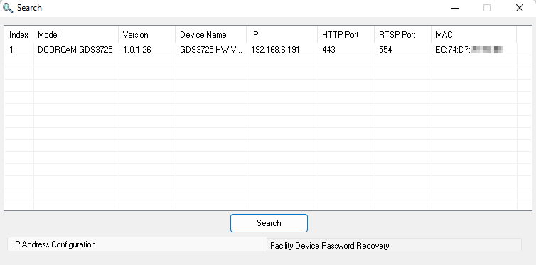
GS search is a program that is used to detect and capture the IP address of the Grandstream facility management solution devices. Below are instructions for using the “GS Search” utility tool:
Download the GS Search utility tool from the Grandstream website using the following link: GS_Search
Double-click on the downloaded file, and the search window will appear.
Click on button to start the discovery for Grandstream devices.
The detected devices will appear in the output field like below.
GS Search Discovery
Using the GDS Manager Utility Tool to Retrieve the GDS3725/GDS3726/GDS3726Q IP Address
Users can retrieve the IP address assigned to the GDS3725/GDS3726/GDS3726Q from the DHCP server log or by using the Grandstream GDS Manager 2 application after installing the free utility provided by Grandstream.
Before discovering the device, ensure that GDS Manager Mode is enabled on the GDS3725/GDS3726/GDS3726Q. If GDS Manager Mode is disabled, the device will not be detected by GDS Manager 2.
Launch GDS Manager 2 and complete the initial setup by configuring an Access Password and specifying the application data storage path. Log in using the configured Access Password.
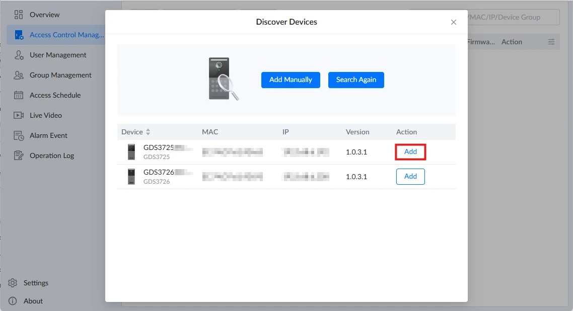
On the GDS Manager 2 interface, access Access Control Management and click Add to open the Discover Devices window.
GDS Manager 2 → Access Control Management → Discovered Devices
In the Discover Devices window, GDS Manager 2 will display the devices detected on the local network. If necessary, click Search Again to perform another device discovery.
Locate the desired GDS3725/GDS3726/GDS3726Q in the discovered device list. The list displays information including the device name, MAC address, IP address, and firmware version.
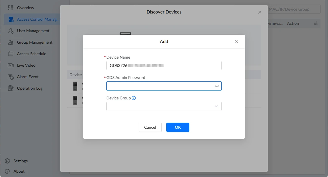
Click Add next to the desired device, enter the device’s Admin Password, assign it to a Device Group if applicable, and click OK.
The device will then be added to Access Control Management, where its assigned IP address and port number can be viewed in the IP field.
Note
If the GDS3725/GDS3726/GDS3726Q does not appear during device discovery, verify that GDS Manager Mode is enabled on the device under Access Control Settings → Basic Settings → Access Control Settings → GDS Manager.
Accessing the GDS3725/GDS3726/GDS3726Q via Static IP
If there is no DHCP server in the network, or the GDS3725/GDS3726/GDS3726Q does not get an IP from the DHCP server, users can connect the GDS3725/GDS3726/GDS3726Q to a computer directly, using a static IP to configure the GDS3725/GDS3726/GDS3726Q.
If no DHCP server is available or the DHCP request times out (after 3 minutes), the GDS3725/GDS3726/GDS3726Q will use its default static IP address: 192.168.0.160
Connect the Ethernet cable from GDS3725/GDS3726 to the computer network port directly.
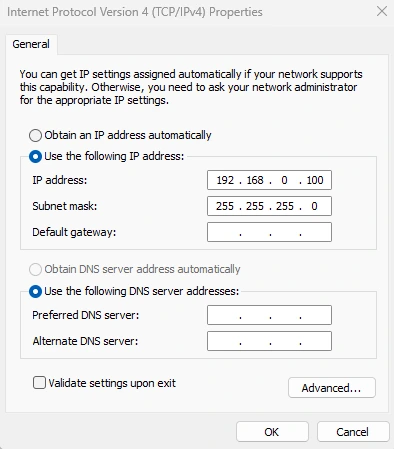
Configure the computer using Static IP: 192.168.0.XXX (1<XXX<255, except for 160) and configure the “Subnet mask” to “255.255.255.0”. Leave the “Default Gateway” to “Blank” like below:
Static IP on Windows
4. Power on the GDS3725/GDS3726/GDS3726Q, using a PoE injector or external DC power.
5. Enter 192.168.0.160 in the address bar of the browser to access the GDS3725/GDS3726/GDS3726Q Web UI.
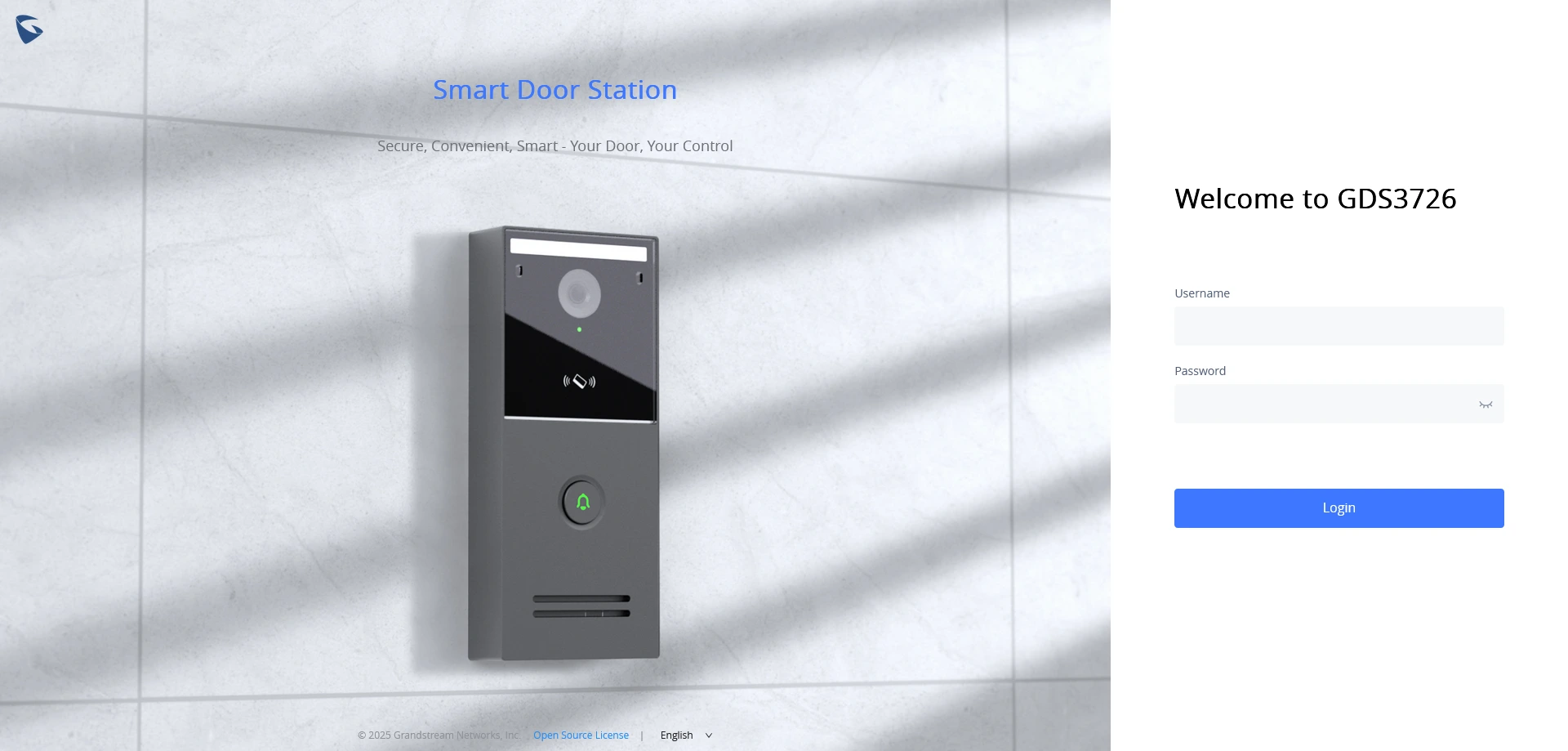
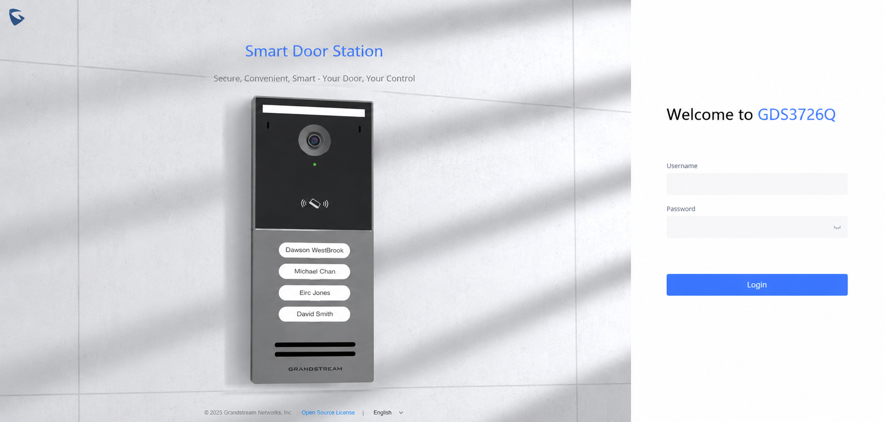
GDS3725/GDS3726/GDS3726Q Web UI Login
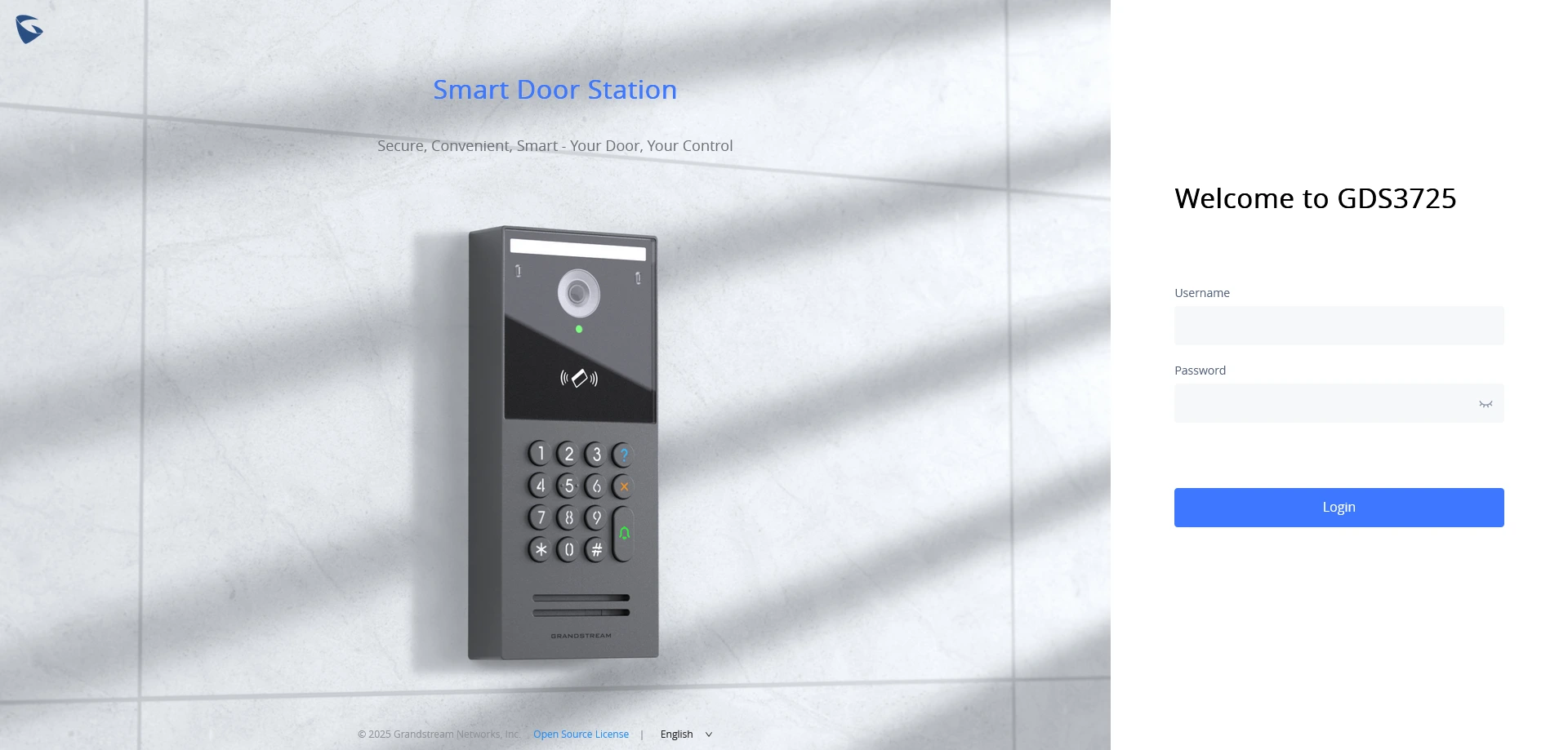
Once the GDS3725/GDS3726/GDS3726Q is accessed through its IP address (whether static or dynamically assigned), the embedded Web User Interface (Web UI) will load in the browser. This interface allows administrators to configure and manage the device.
Upon accessing the Web UI, a login screen will appear prompting for credentials: