Introduction
The L-Shaped Bracket is used for mounting compatible Grandstream GDS series units onto a wall or stud.
It can also work with an optional In-Wall Mounting Kit for a more embedded installation.
This guide summarizes the illustrated procedure and required parts.
Package Content
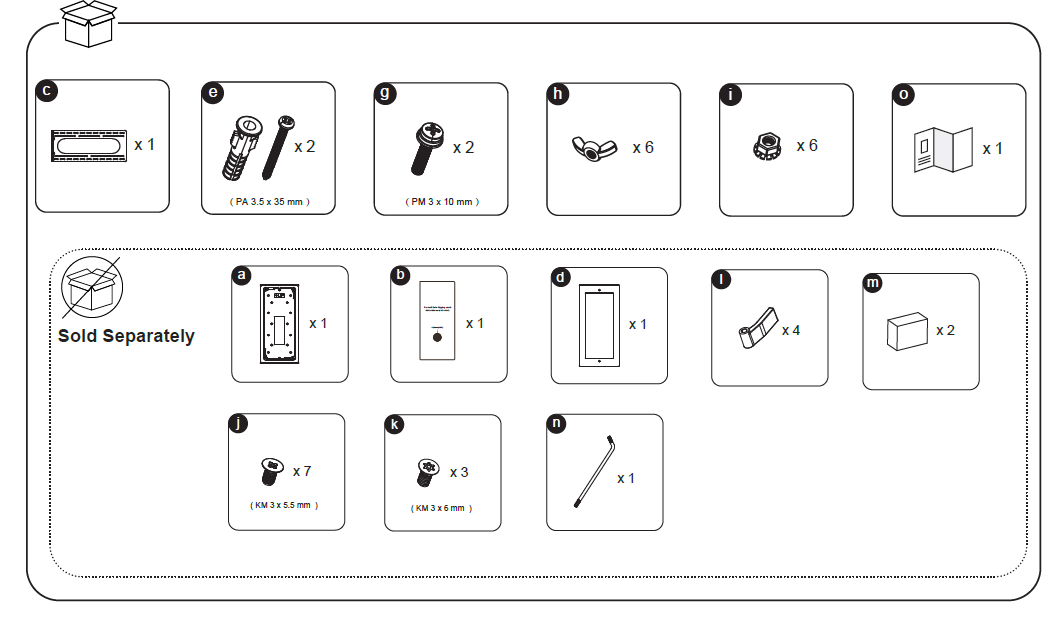
Included in the Box
| Label | Item Description | Quantity | Specification |
|---|---|---|---|
| c | L-Shaped Bracket | ×1 | — |
| e | Plastic Wall Anchor + Screw | ×2 | PA 3.5 × 35 mm |
| g | Screw | ×2 | PM 3 × 10 mm |
| h | Wing Nut | ×6 | — |
| i | Nut | ×6 | — |
| o | Quick Installation Guide (Leaflet) | ×1 | — |
Sold Separately (Required for In-Wall Installation)
| Label | Item Description | Quantity | Specification |
|---|---|---|---|
| a | In-Wall Bracket | ×1 | — |
| b | Mounting Template | ×1 | — |
| d | Front Frame | ×1 | — |
| j | Screw | ×7 | KM 3 × 5.5 mm |
| k | Screw | ×3 | KM 3 × 6 mm |
| l | Cable Clamp | ×4 | — |
| m | Back Box | ×2 | — |
| n | Allen Key | ×1 | — |
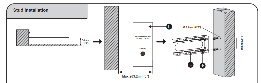
Stud Installation
Prepare the Installation Area
- Choose a suitable stud or wall section for the bracket placement.
- Ensure there is at least 38 mm (1.5”) depth clearance behind the wall surface.
Mark and Drill
- Use the mounting template (b) to mark the screw positions.
- Drill two holes of Ø 6.5 mm (0.26”) on the marked points, maintaining a vertical spacing of 56 mm (2.2”) between them.
Fix the Bracket
- Align the L-Shaped Bracket (c) over the drilled holes.
- Insert the plastic anchors and screws (e) through the bracket into the wall.
- Tighten the screws until the bracket is firmly secured and aligned flat to the wall.
Verify Alignment
- Ensure the bracket opening is centered within the maximum width of 203.2 mm (8”) as shown.
- Check that it sits flush and level before proceeding to device mounting.
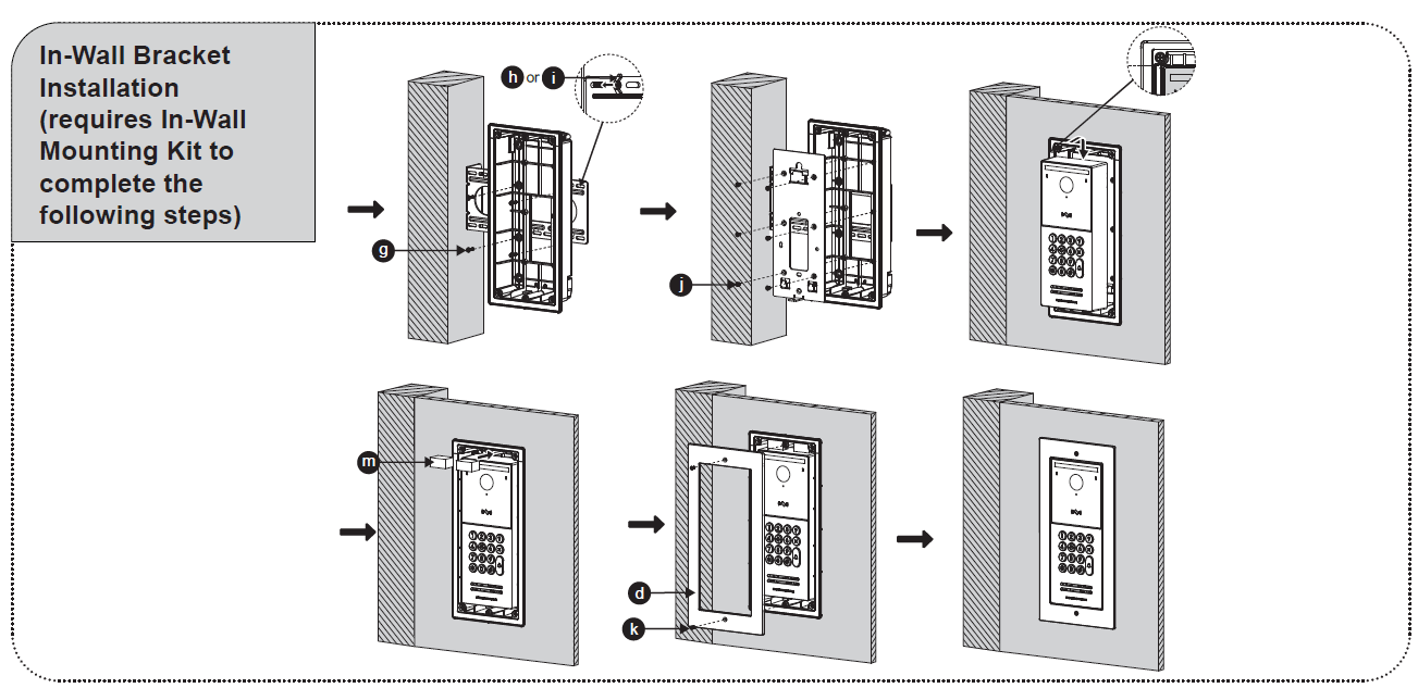
In-Wall Bracket Installation
(Requires In-Wall Mounting Kit sold separately)
- Install the In-Wall Bracket (a)
- Insert the in-wall bracket into the prepared opening.
- Secure it to the stud or wall frame using PM 3 × 10 mm screws (g) and wing nuts (h) or nuts (i) as shown.
- Tighten screws evenly to fix the bracket in place.
- Attach the Device (GDS Unit)
- Place the device into the mounted bracket and fasten it using KM 3 × 5.5 mm screws (j).
- Ensure all cables are properly routed through the bracket before tightening.
- Mount the Back Boxes (m)
- Insert the back boxes on both sides of the bracket as illustrated.
- Use the designated screw holes to secure them.
- Attach the Front Frame (d)
- Position the front frame over the installed unit.
- Fix it using KM 3 × 6 mm screws (k).
- Tighten with the Allen key (n) for a clean, flush finish.
- Final Check
- Ensure the device is fully seated and level within the wall.
- Verify that the front panel fits securely without gaps or misalignment.