

1.Introduction
The WireGuard feature enables a the WP8x6 to establish a secure VPN connection to a peer using configured keys, IP addressing, and routing parameters. Once connected, the device can route traffic through the VPN tunnel and reflect the WireGuard client address in system status and application to signal the connection according to the configured settings.
2. WireGuard Configuration
This section maps to a “WireGuard Configuration”
2.1 Enable WireGuard®
- WireGuard is disabled by default.
- The administrator must manually enable it.

2.2 Client Private Key Generation
- WireGuard only supports 32‑byte keys encoded in Base64.
- Clicking Create automatically creates a client private key.

2.3 Client Public Key
- The client public key is automatically generated from the private key.
- A Copy action allows exporting the public key.

2.4 Client IP Address
- Configure the IP address assigned to the client by the server.
- Format:
IP/SubnetLength(example:10.0.0.1/24). - If the subnet mask length is omitted, /32 is used by default.

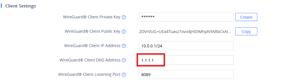
2.5 Client DNS Address
- Configure DNS server address(es) used by the client.
- Up to two DNS addresses are supported.
- Multiple DNS servers can be defined, and must be comma‑separated, but only when using a .conf file
- If not configured, the client uses the same DNS as the Wi‑Fi connection.
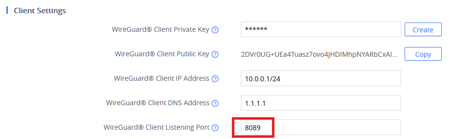
2.6 Client Listening Port
- Defines the port used by the client to connect to the WireGuard service.
- If not specified, a random port is automatically used.
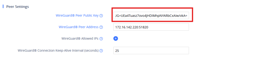
2.7 Peer Public Key
- Configure the peer (server) public key.
- Only 32‑byte Base64‑encoded keys are supported.
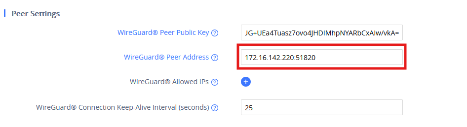
2.8 Peer Address
- Enter the peer’s IP address, including the listening port.
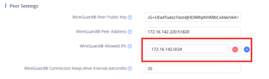
2.9 Allowed IPs
- Defines which IP addresses the client can access via the VPN server peer.
- Multiple entries are allowed.
- If left blank, 0.0.0.0/0 is used (no restrictions).
- Example format:
10.0.0.0/24,10.2.2.2/32. - If subnet mask length is omitted, /32 is used by default.
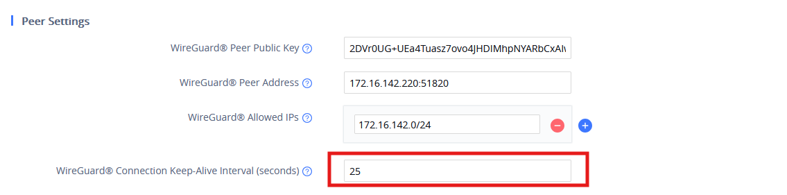
2.10 Keep‑Alive Interval
- Defines the interval (in seconds) at which the client sends keepalive packets.
- If left blank, no keepalive packets are sent.
2.11 One‑Click Import
- Supports importing WireGuard server configuration files in
.confformat. - Maximum supported file size: 1 MB.

3. WireGuard Connection Status
This section describes the behavior of the device after a successful connection to the wireguard VPN
3.1 Web Interface Status
After a successful connection:
- WireGuard server information
- Assigned IP address
- Routing details are displayed under:
WP8x6 Web Interface → Status → Network Status
3.2 LCD Interface Status
After a successful connection:
- WireGuard server and IP address information are displayed under:
LCD Interface → Status → Network Status → VPN
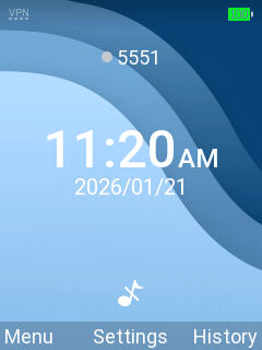
3.3 VPN Icon Behavior
- During connection attempt: VPN icon appears gray.
- Connection successful: VPN icon lights up.
- Connection failure: No VPN icon is displayed.
3.4 Concurrent VPN Connections
- When WireGuard and OpenVPN are connected simultaneously:
- A “+” symbol appears next to the VPN icon.
4. WireGuard Application Behavior (SIP / NAT Traversal)
4.1 NAT Traversal = WireGuard
When “WireGuard” is selected in:
Accounts → Accounts → General Settings → NAT Traversal
- During registration:
- WireGuard client address is included in Via and Contact headers.
- During calls:
- WireGuard client address is included in Via, Contact, and SDP.
4.2 NAT Traversal = Auto (wg0 route used)
If “Auto” is selected and registration uses the wg0 route:
- During registration:
- WireGuard client address is included in Via and Contact headers.
- During calls:
- WireGuard client address is included in Via, Contact, and SDP.
4.3 NAT Traversal = Auto (wg0 route not used)
If “Auto” is selected and registration does not use the wg0 route:
- Wi‑Fi IP address is included in:
- Via headers
- Contact headers
- SDP
5. Example (Configuration Illustration)
This example demonstrates the correct settings to achieve a successful WireGuard client connection.
Example configuration:
- Client IP Address:
10.0.0.1/24 - DNS:
8.8.8.8,1.1.1.1 - Peer Address:
vpn.example.com:51820 - Allowed IPs:
10.0.0.0/24 - NAT Traversal:
WireGuard
Observed behavior:
- Client connects to WireGuard service
- VPN icon lights up on LCD
- WireGuard status appears in Web and LCD interfaces
- SIP registration and calls carry the WireGuard client address in signaling headers