Introduction
The GWN7670E and GWN7673 are enterprise-grade dual-band Wi-Fi 7 access points designed for SMBs, offices, retail spaces, schools, and other medium-scale indoor wireless deployments. Both models support BE3600 Wi-Fi 7 performance with 2×2:2 MU-MIMO on the 2.4 GHz band and 3×3:2 MU-MIMO on the 5 GHz band, along with DL/UL OFDMA technology to deliver high wireless throughput and reliable connectivity for high-density environments.
The GWN7670E and GWN7673 feature advanced Wi-Fi 7 technologies, including Multi-Link Operation (MLO), Multi-RU, Preamble Puncturing, and 4096-QAM, helping improve wireless efficiency and user experience. Both models also include Xtra Range 2.0 technology on the 5 GHz band to enhance signal penetration and extend wireless coverage.
For easy deployment and management, the GWN7670E and GWN7673 can be managed through their local Web UI, GDMS Networking, GWN Manager, or the GWN App. Both models support up to 512 concurrent Wi-Fi clients, up to 32 SSIDs, advanced QoS, secure authentication options, captive portal, mesh networking, and a 2.5 GbE PoE+ uplink port, making them suitable for reliable indoor Wi-Fi 7 deployments.
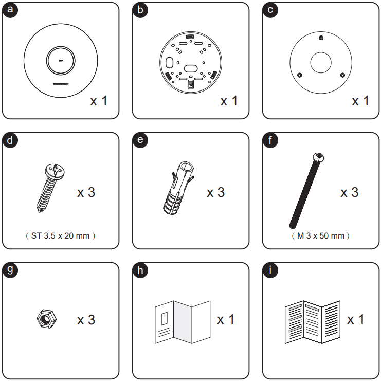
Package Content
| Item | Included component |
|---|---|
| a | 1 × GWN7670E/GWN7673 access point |
| b | 1 × Mounting bracket |
| c | 1 × Ceiling mounting bracket |
| d | 3 × Screws (ST 3.5 × 20 mm) |
| e | 3 × Plastic expansion bolts |
| f | 3 × Screws (M3 × 50 mm) |
| g | 3 × Nuts |
| h | 1 × Quick Installation Guide |
| i | 1 × Regulatory paper |
Powering and Connecting the GWN7670E/GWN7673
The GWN7670E and GWN7673 each provide one 2.5 GbE Ethernet port with PoE+ support for power and network access.
NET/2.5G/PoE+ Port:
- Supports 2.5 Gigabit Ethernet.
- Provides both network connectivity and power through a PoE+ connection.
- Suitable for enterprise access deployments that require high-speed Wi-Fi 7 uplink performance.
To Power and Connect:
- Connect an RJ45 Ethernet cable to the NET/2.5G/PoE+ port on the access point.
- Plug the other end into a PoE+ (802.3at) compliant switch or injector.
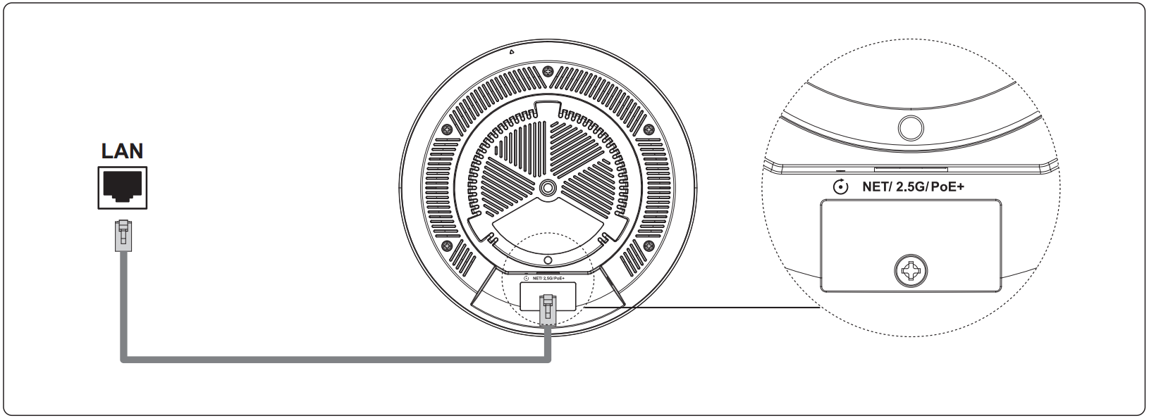
Recommendation: Use a PoE+ (802.3at) compliant switch or injector to power the access point and provide network access through the 2.5 GbE uplink port.
Wall Mounting
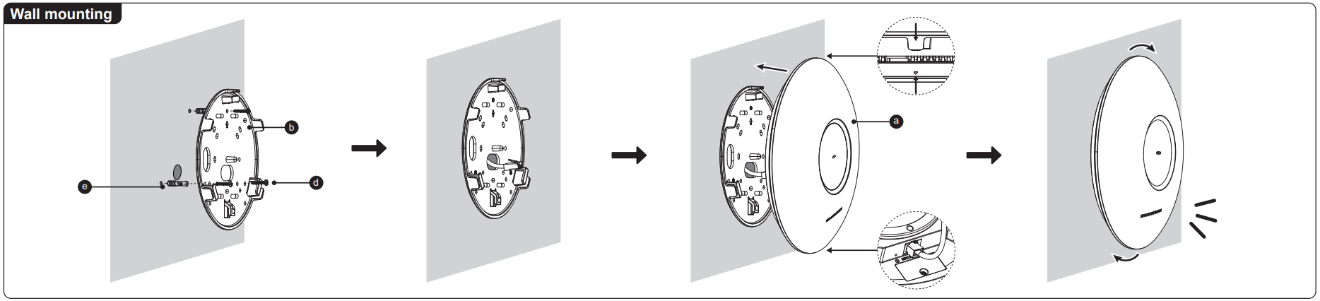
- Connect the Ethernet cable (RJ45) to the correct port of the access point.
- Align the arrow on the access point with the arrow on the locking tab of the mounting bracket and ensure that the device is firmly seated on the mounting bracket.
- Turn the device clockwise until it locks into place and fits the locking tab.
- Connect the Ethernet cable (RJ45) to the correct port of the access point.
- Align the arrow on the access point with the arrow on the locking tab of the mounting bracket and ensure that the device is firmly seated on the mounting bracket.
- Turn the device clockwise until it locks into place and fits the locking tab.
Ceiling Installation
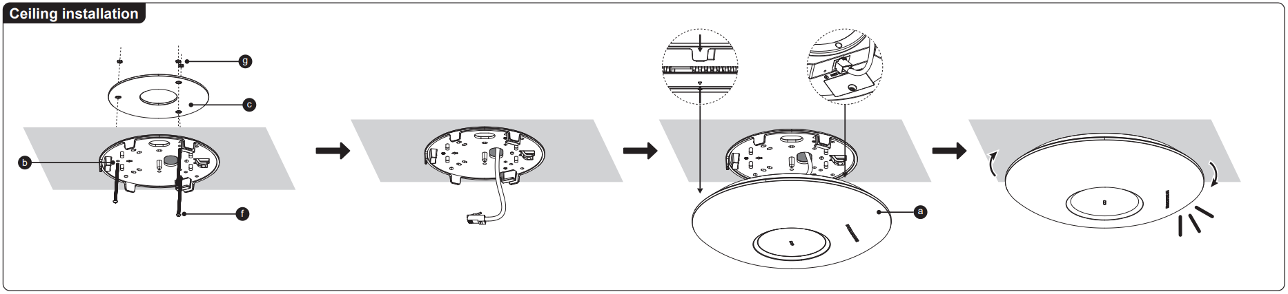
- Remove the ceiling tile.
- Place the ceiling backing plate in the center of the ceiling tile and mark the mounting screw holes (screw holes DIA 5.5mm, reticle hole DIA 25mm).
- Insert the screws through the mounting bracket.
- Connect the Ethernet cable (RJ45) to the correct port of the access point.
- Align the arrow on the access point with the arrow on the locking tab of the mounting bracket, ensure that the device is firmly seated, and connect the network cable.
- Turn the device clockwise until it locks into place and fits the locking tab.
Accessing Web Configuration
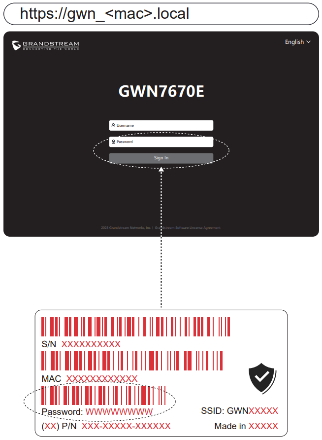
The GWN7670E and GWN7673 can be used as standalone access points out of the box, or after a factory reset with Wi-Fi enabled by default.
After powering the access point and connecting it to the network, the device will broadcast a default SSID based on its MAC address (GWN followed by the last six digits of the MAC address) and a random password.
Adding the device to the GDMS.Cloud
To add a GWN7670E or GWN7673 to the cloud, navigate to the GDMS Networking Cloud by visiting https://www.gdms.cloud. Log in with your GDMS account credentials, then register and manage the device within the platform.