


Overview
The GWN7670LR is a long-range Wi-Fi 7 access point, ideal for medium-to-large businesses that need to provide long-range coverage. It offers IP66-level weatherproof capability, dual-band 2×2:2 MIMO with DL/UL OFDMA technology and a sophisticated antenna design for maximum network throughput and expanded Wi-Fi coverage range. It supports flexible switching between internal directional antennas and external omnidirectional antennas. It can be combined with directional antenna and PTMP technology (pending) to serve as a professional long-range wireless bridge. With 4096 QAM modulation, Wi-Fi 7 achieves a significant increase in data transfer rates. MLO technology optimizes spectrum resource utilization to ensure a smooth experience for every user. To ensure easy installation and management, the GWN7670LR uses a controller-less distributed network management design in which the controller is embedded within the product’s Web User Interface. The GWN7670LR is also supported by GDMS Networking and GWN Manager, Grandstream’s cloud and on-premise Wi-Fi management platform. It is the ideal Wi-Fi AP for voice-over-Wi-Fi deployments and offers a seamless connection with Grandstream’s Wi-Fi capable IP phones. With support for advanced QoS, low-latency real- time applications, mesh networks, captive portals, BLE 5.3, 256 concurrent clients per AP, 1×2.5 Gigabit network port with PoE+ and 1x 2.5 Gigabit SFP port. GWN7670LR is an ideal long-range Wi-Fi access point for enterprises, multiple floor offices, warehouses, parks, hospitals, schools and more.
Package Contents
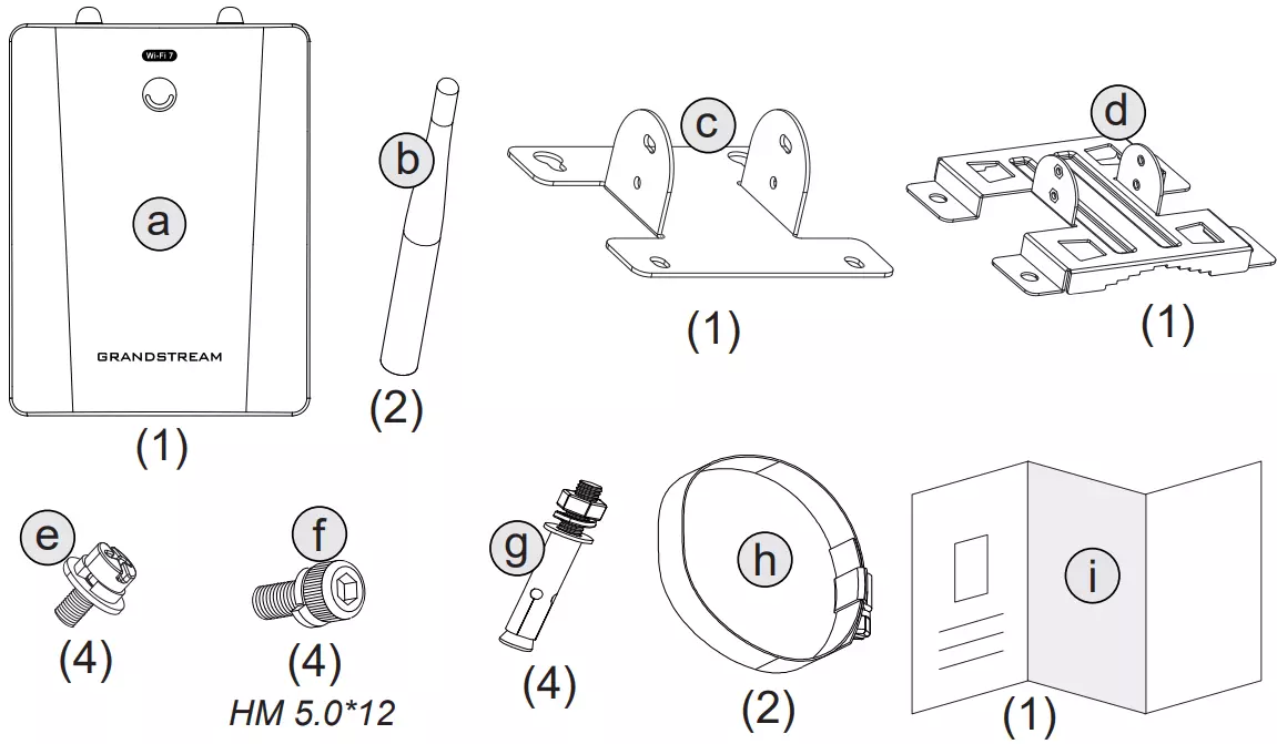
Label | Description |
a | 1x GWN7670LR Access Point |
b | 2x Antenna |
c | 1x Base Bracket (mounted on the back of the device) |
d | 1x Wall/Pole Mount Bracket |
e | 4x Screws |
f | 4x HM 5.0*12 Screws |
g | 4x Expansion Bolts |
h | 2x Metal Straps |
i | 1x Quick Installation Guide and Regulatory Paper |
Package Contents
GWN7670LR Ports
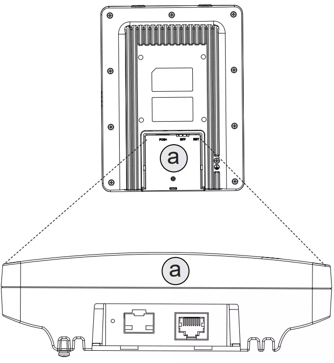
Port | Description |
SFP Port | 2.5G SFP Port |
NET/POE 2.5G | Ethernet RJ45 port 2.5Gbps to your router or another GWN76xx, support PoE+ In. |
RESET | Factory reset button. Press for 7 seconds to reset factory default settings. |
Ports
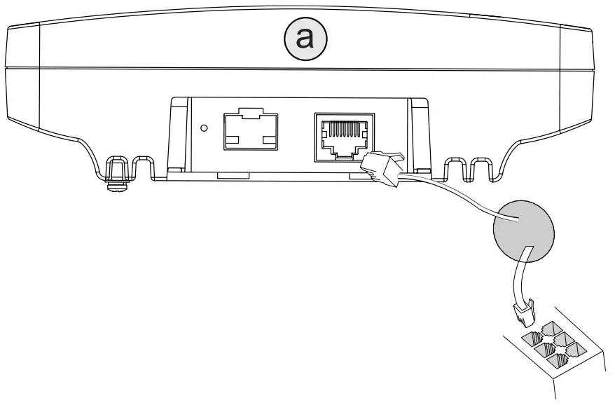
Powering and Connecting the GWN7670LR
GWN7670LR can be powered on using PoE+ switch using the following steps:
Step 1: Plug an RJ45 Ethernet cable into the network port of the GWN7670LR.
Step 2: Plug the other end into the uplink port of the power over Ethernet (PoE+) switch.
Hardware Installation
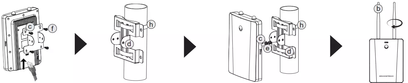
GWN7670LR can be mounted on the wall or on a metal bar, Please refer to the following steps for the appropriate installation.
Preventing Water Ingress
- Create a drip loop: Before connecting the cable to the AP, form a downward loop below the connection point. This allows water to drain away instead of traveling along the cable into the AP connection.
- Seal cable-entry points: Properly seal any opening where the cable passes through a wall or enters a building or enclosure to prevent water ingress.
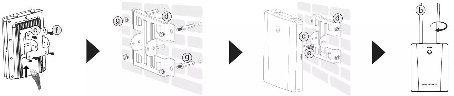
Wall Mount
- Connect the Ethernet (RJ45) cable to the correct port on the GWN7670LR.
- Attach the Base Bracket (c) to the back of the device using the HM 5.0×12 screws (f).
- Drill four holes on the wall using the Mounting Bracket (d) as a template.
- Insert the Expansion Bolts (g) into the holes and secure the Mounting Bracket (d) to the wall.
- Align the Base Bracket (c) with the Mounting Bracket (d) and fasten them together using the Screws (e).
- Attach both Antennas (b) to the device.
- Ensure the access point is securely fixed and all connections are tight.
Pole Mount
- Connect the Ethernet (RJ45) cable to the correct port on the GWN7670LR.
- Attach the Base Bracket (c) to the back of the device using the HM 5.0×12 screws (f).
- Place the Mounting Bracket (d) against the pole and loop the Metal Straps (h) through the bracket slots.
- Tighten the Metal Straps (h) securely around the pole to hold the Mounting Bracket (d) in place.
- Align the Base Bracket (c) on the device with the Mounting Bracket (d) and fasten them together using the Screws (e).
- Attach both Antennas (b) to the access point.
- Check that the device is firmly mounted and the connections are stable.
Antenna Application Scenarios
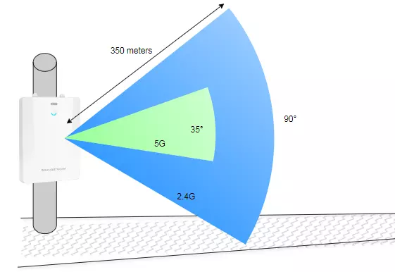
Directional antennas (internal)
- When to use
Long, narrow coverage zones or sectorized areas with higher user density where limiting spillover and interference matters. Typical environments include tunnels, stadium stands, corridors, and platforms.
- Why it fits
The internal directional antennas provide focused coverage for greater reach and tighter interference control. Typical beamwidths are ~90° on 2.4 GHz and ~35° on 5GHz.
- Range guidance
For links or sectors beyond ~200 m, directional coverage is recommended. In open conditions, the GWN7670LR can reach approximately 350 m.
Omnidirectional antennas (external)
- Required hardware
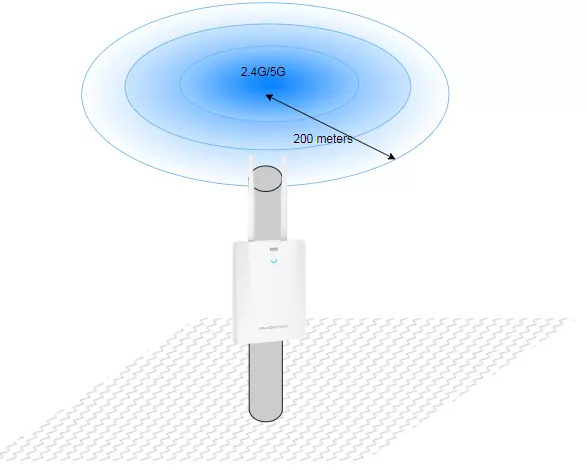
Install the external omnidirectional antennas to enable omni coverage. Attach both antennas securely, keep them vertical, and ensure clear space around the AP.
- When to use
Open areas with evenly distributed users and no preferred direction of coverage. Typical environments include playgrounds, exhibition areas, and small plazas.
- Why it fits
A 360° radiation pattern delivers uniform coverage around the AP for nearby clients on both 2.4GHz and 5GHz, simplifying placement in compact open spaces.
- Range guidance
Plan for a practical radius of ≤ ~200 m with external omni antennas. If the area is larger or needs tighter control, use the internal directional antennas instead.
- Installation notes
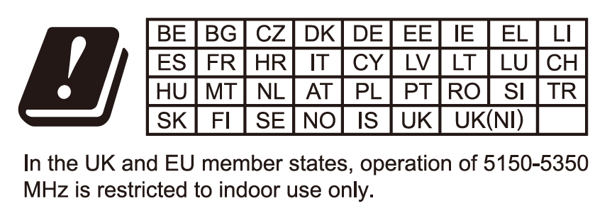
Mount at an appropriate height, avoid major obstructions, and route cabling to minimize interference. Follow local regulatory limits for transmit power and channels.
General note: Actual performance varies with mounting height, obstacles, interference, client capabilities, and regulatory constraints.
Mixed antenna configuration
The GWN7670LR supports independent antenna selection per band, allowing a hybrid configuration. For example, you can enable the external antenna on 5GHz for short-range omnidirectional coverage, while keeping 2.4GHz on the internal directional antenna for longer-range, focused coverage or vice versa.
This setup is ideal in environments where different frequency bands serve different roles, such as:
- 2.4GHz directional for corridor coverage or extended reach
- 5GHz omni for nearby high-bandwidth clients in open areas
How it works:
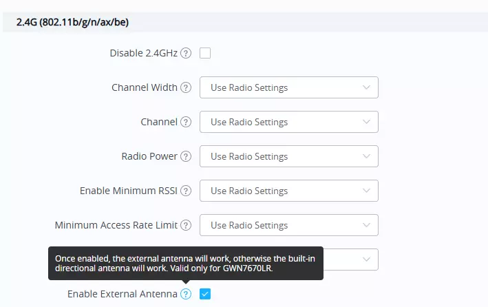
The “Enable External Antenna” setting appears separately under both the 2.4G and 5G radios in the configuration interface. Enabling it on one band activates the external antenna for that band only. The other band will continue to use the internal directional antenna by default.
Example use case:
A school hallway might require long-range 2.4G coverage (directional), while nearby classrooms benefit from local 5G coverage (omni). With one device, both needs can be met by enabling the external antenna only on the 5G radio.
Configuration step (required for Omnidirectional setup)
After installing the external antennas, log in to the device and enable the external antenna setting:
- Go to Access Point → Configuration.
- For each radio you will use with the external antennas (2.4 GHz and/or 5 GHz), enable External Antenna.
- Save/Apply.
Connect to GWN7670LR Default Wi-Fi Network
GWN7670LR can be used as a standalone access point out of the box, or after a factory reset with Wi-Fi enabled by default.
After powering the GWN7670LR and connecting it to the network, GWN7670LR will broadcast a default SSID based on its MAC address GWN[MAC’s last 6 digits] and a random password.
Accessing the Configuration Interface
A computer connected to the GWN7670LR’s SSID, or to the same network as the GWN7670LR can discover and access its configuration interface using one of the below methods:
Method 1: Discover GWN7670LR using its MAC Address
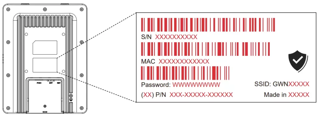
- Locate the MAC address on the MAC tag of the unit, which is on the underside of the device, or on the package.
- From a computer connected to the same network as the GWN7670LR, type in the following address using GWN7670LR’s MAC address on your browser https://gwn_<mac>.local
Method 2: Discover GWN7670LR using GWN Discovery Tool
- Download and install GWN Discovery Tool from the following link: https://www.grandstream.com/tools/GWNDiscoveryTool.zip
- Open the GWNDiscoveryTool, and click on Scan.
- The tool will discover all GWN76xx Access Points connected to the network showing their MAC and IP addresses.
- Click on Manage Device to be redirected directly to the GWN7670LR’s configuration interface, or type in manually the displayed IP address on your browser.
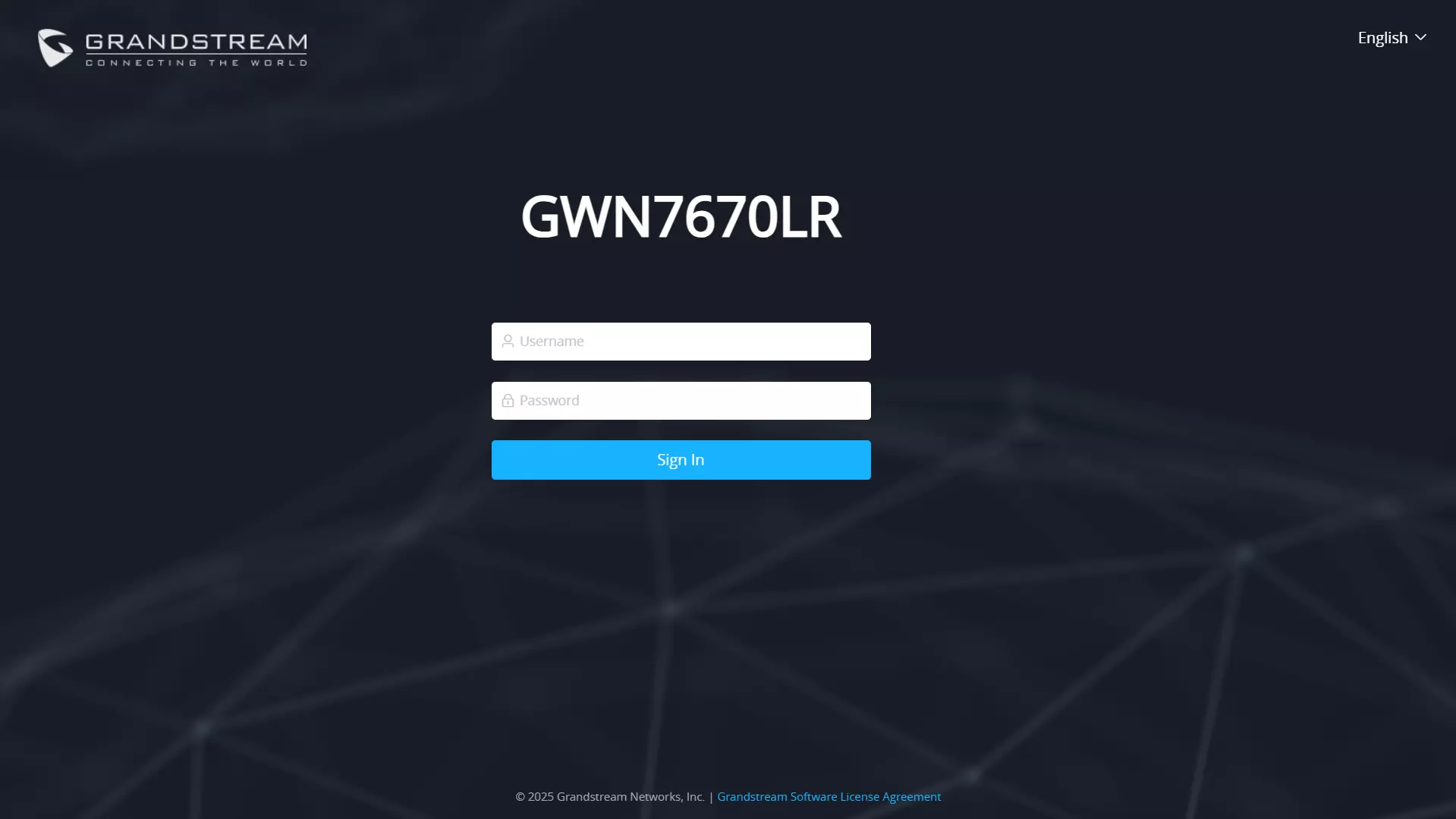
- Enter the username and password to log in. (The default administrator username is “admin” and the default random password can be found on the sticker on the GWN7670LR).
Refer to online documents and FAQ for more detailed information:
https://www.grandstream.com/our-products

For Certification, Warranty, and RMA information,
please visit www.grandstream.com