


INTRODUCTION
The Grandstream GWN780x series includes Layer 2+ managed network switches designed to support scalable, secure, and high-performance business networks for small-to-medium businesses.
- GWN7801 / GWN7801P
- GWN7802 / GWN7802P
- GWN7803 / GWN7803P
- GWN7806 / GWN7806P
All models in the GWN780x series support advanced VLAN for flexible traffic segmentation, QoS for network traffic prioritization, IGMP/MLD Snooping for performance optimization, and comprehensive security capabilities. PoE models are available to power IP phones, IP cameras, Wi-Fi access points, and other PoE endpoints.
The GWN780x series can be managed through multiple methods, including a local web user interface, command-line interface (CLI), and integration with Grandstream’s GDMS Networking and GWN Manager platforms, providing complete end-to-end network management options.
PRODUCT OVERVIEW
Technical Specifications
The GWN780x Series Technical Specifications guide below provides model-specific interfaces, performance, PoE, power, environmental, physical, and compliance information.
| Series | Models | Technical Specifications |
|---|---|---|
| GWN780x | GWN7801(P), GWN7802(P), GWN7803(P), GWN7806(P) | GWN780x Series Technical Specifications |
INSTALLATION
Select the applicable switch model below to open its Quick Installation Guide. Each guide provides package contents, port and LED information, power and network connections, and mounting instructions.
| Series | Models | Quick Installation Guide |
|---|---|---|
| GWN780x | GWN7801(P), GWN7802(P), GWN7803(P) | GWN780x(P) Quick Installation Guide |
| GWN7806, GWN7806P | GWN7806(P) Quick Installation Guide |
GETTING STARTED
LED Indicators
The front panel of the GWN780x has LED indicators for power and interface activities, the table below describes the LED indicators’ status.
LED Indicator | Status | Description |
System Indicator | Off | Power off |
Solid green | Booting | |
Flashing green | Upgrade | |
Solid blue | Normal use | |
Flashing blue | Provisioning | |
Solid red | Upgrade failed | |
Flashing red | Factory reset | |
Port Indicator | Off |
|
Solid green | Port connected and there is no activity | |
Flashing green | Port connected and data is transferring | |
Solid yellow | Ethernet port connected, and there is no activity and PoE powered | |
Flashing yellow | Ethernet port connected, data is transferring and PoE powered | |
Alternately flashing yellow and green | Ethernet port failure | |
PWR/RPS Indicator | Off | Uninserted or failure |
Solid Green |
| |
LED Indicators
Access & Configure
Login Using the Console Port
- Use the console cable to connect the console port of switch and the serial port of PC.
- Open the terminal emulation program of PC (e.g. SecureCRT), enter the default username and password to login. (The default administrator username is “admin” and the default random password can be found at the sticker on the GWN780x switch).
Login Remotely Using SSH
- Enter “cmd” in PC/Start.
- Enter ssh <gwn780x_IP> in the cmd window.
- Enter the default username and password to login. (The default administrator username is “admin” and the default random password can be found at the sticker on the GWN780x switch).
GWN Switches support also Web CLI.
Configure Using GDMS Networking
Type https://www.gdms.cloud in the browser, and enter the account and password to login the cloud platform. If you don’t have an account, please register first or ask the administrator to assign one for you.
Login Using the Web UI
The GWN780x embedded Web server responds to HTTPS GET/POST requests. Embedded HTML pages allow users to configure the device through a Web browser such as Microsoft Edge, Mozilla Firefox, or Google Chrome.
- A PC uses a network cable to correctly connect any RJ45 port of the switch.
- Set the Ethernet (or local connection) IP address of the PC to 192.168.0.x (“x” is any value between 1-253), and the subnet mask to 255.255.255.0, so that it is in the same network segment with switch IP address. If DHCP is used, this step could be skipped.
- Type the switch’s default management IP address https://<GWN780x_IP> in the browser, and enter the username and password to log in. (The default administrator username is “admin” and the default random password can be found at the sticker on the GWN780x switch).
CLI Access
In addition to the web-based configuration, the GWN780x series can also be configured using a Command Line Interface (CLI). For detailed instructions on using the CLI, please refer to the GWN78xx CLI User Guide.
Web GUI Languages
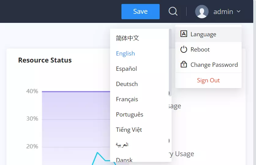
The GWN780x web GUI supports many languages including English, Simplified Chinese, Spanish, French etc.
To change the default language, select the displayed language at the bottom of the web GUI either before or after logging in.
Search
In case it’s hard to go through every single section, GWN780x Switches have search functionality to help the user find the right configuration, settings or parameters, etc.
On the top of the page, there is a search icon, the user can click on it and then enter the keyword relevant to his search, then he will get all the possible locations of that keyword.
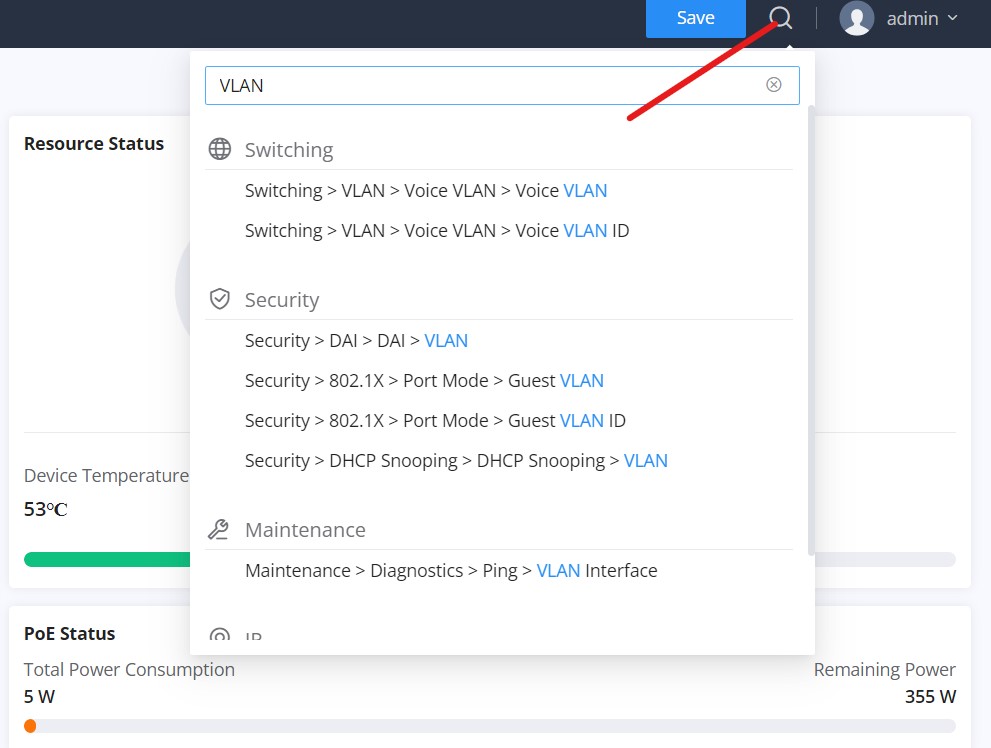
It’s also possible to search through menus and sub-menus, and once the user clicks on the search result, they will jump directly to the specified page, please see the figure below:

OVERVIEW
Overview is the first section that displays System information in the first page “System Info” and Port status on the second page “Port Info”. This section provides the user with a general and global view about the GWN780x system and ports status for easy monitoring.
System Info
System Info is the first page after a successful login to the GWN780x Web Interface. It provides an overall view of the GWN780x Switch information presented in a Dashboard style for easy monitoring including basic info, Resources Status, PoE Status and System Events.

To name the device please click on  , then enter the desired name.
Basic Info | Displays Device and System general information that includes (Device name, MAC Address, Default Gateway, System Time, System Version etc.) |
Resource Status | Displays in real time the usage of CPU and Memory. |
PoE Status | Shows the Total Power Consumption and the remaining Power in mA. |
System Events | Diplays the total number of events for each category (Emergency, Alert, Warning etc). Note: Clicking on any events category will redirect you to the Diagnostics page for further details. |
Fan | Displays the fans operation status and speed. |
Power Supply | Shows the status of the built-in power supply as well as the RPS (Redundant Power Supply). |
System Info page
Port Info
This page on the GWN switches provides comprehensive port statistics, PoE power supply information, and detailed port and neighbor information. It helps users monitor network performance and manage connected devices efficiently.
- Port Info
The “Port Info” section visually displays the status and speed of each port, using different colors for speeds and states. Users can quickly identify active, inactive, or problematic ports and their PoE power status.
- Basic Info and Neighbor Info
The “Basic Info” section shows specific details for a selected port, including its status and settings. The “Neighbor Info” section provides information about the device connected to the port, such as hostname and current traffic rates.

- Statistics
The “Statistics” section offers detailed metrics on network traffic through the switch. It includes data on octets, packets, and discards, which is crucial for monitoring performance and troubleshooting.
- PoE Power Supply / Fiber Info
If the selected port is PoE-capable, the “PoE Power Supply” section shows power supply status and usage. If the port is SFP, the “Fiber Info” section displays details like signal loss, temperature, RX, and TX power.

The following table explains the color mode and the symbols used:
 | Grey: Linkdown |
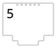 | White: shutdown |
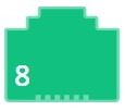 | Green: Ethernet RJ45 port with 1000 Mbps speed |
 | Light green: Ethernet RJ45 port with 100 Mbps/10 Mbps speed |
 | Red: ErrDisable |
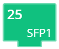 | Green: SFP/SFP+ Port set to 1000Mbps |
 | Purple: SFP Port set to 2.5Gbps |
 | Blue: SFP+ port set to 10Gbps |
 | Symbol: PoE Power is enabled. |
Port Info
Note: a PoE symbol and color code combination is also possible. Ex:  in this case, the port is using 1000 Mbps speed and also using PoE at the same time.
Icons Description:
- Basic Info: The edit icon forwards users to the Port Basic Settings page, where they can modify the port settings such as Description, Speed, Duplex Mode, and Flow Control, or enable/disable the port.
- Neighbor Info: The details icon forwards users to the LLDP/LLDP-MED Neighbor Info page. Here, users can view additional information about the connected devices, including chassis ID, port ID, device name, system description, and survival time.
- PoE Power Supply / Fiber Info: The details icon forwards users to the respective detailed pages. For PoE, it forwards to the PoE Interface page showing detailed information about PoE settings for each port. For Fiber, it forwards to the Fiber Module page, displaying comprehensive fiber details such as signal loss, temperature, RX, and TX power.
- Statistics: The clear icon clears the displayed statistics.
SWITCHING
Switching section is used to configure ports settings, link Aggregation, VLAN, Spanning Tree etc.
Port Basic Settings
On this page, you can configure the basic parameters for GWN780x Switch ports, like disabling or enabling the port, adding Description, specifying the speed by default is Auto, Duplex Mode, and Flow Control. There is also a filter on in case you want to edit only the Copper ports which are the Gigabit Ethernet ports or Fiber ports which are the SFP+ ports.
To configure a port, please navigate to Web UI → Switching → Port Basic Settings.
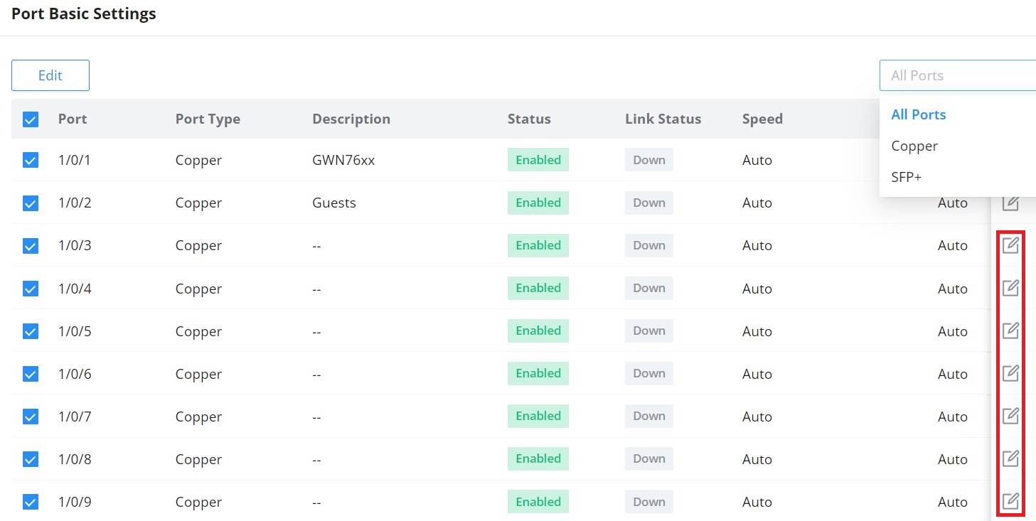
To configure a port, click on the “Edit” icon under the operation column.

Users can define schedules for specific ports, this is to enable precise control over when configurations are applied. These schedules dictate the exact times during which port settings will take effect.
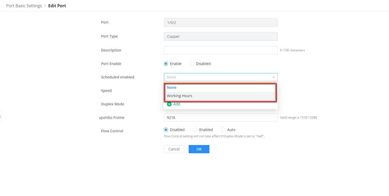
| Port | The selected port to be configured. It can be either a Gigabit Ethernet port or an SFP port. |
|---|---|
| Port Type | Displays the port type (Copper or SFP). |
| Description | Configures the interface description, such as its intended use. The description can contain up to 128 characters, including numbers, letters, and special characters. |
| Port Enable | Sets whether the interface is enabled. The interface is enabled by default. |
| Scheduled Enabled | From the drop-down list, select the schedule during which the port, including a physical or LAG port, will be enabled. |
| Speed |
Sets the interface rate. The available options are Auto, 10 Mbps, 100 Mbps, and 1000 Mbps. The default is Auto. Notes:
|
| Duplex Mode |
Sets the interface duplex mode. The Gigabit Ethernet port options are Auto-negotiation, Full-duplex, and Half-duplex. The default is Auto-negotiation.
Notes:
|
| Jumbo Frame | Specifies the jumbo-frame size. The valid range is 1518–12288 bytes. The default is 9216 bytes. |
| Flow Control |
Sets flow control on the interface. The options are Disabled, Enabled, and Auto. The default is Disabled. When enabled, a congested device notifies its peer to pause packet transmission temporarily, helping prevent packet loss. Note: Optical ports do not support Auto-negotiation mode. |
Port Group
The port group feature allows administrators to logically bundle specific ports together under one group with a corresponding group ID, this can be useful when classifying the switch ports for identifying the usage of each set of ports, for example, ports 1 to 8 can be set with ID 20, these will be the ports connecting Security devices.
Port group settings can facilitate quick batch settings for port group ports.
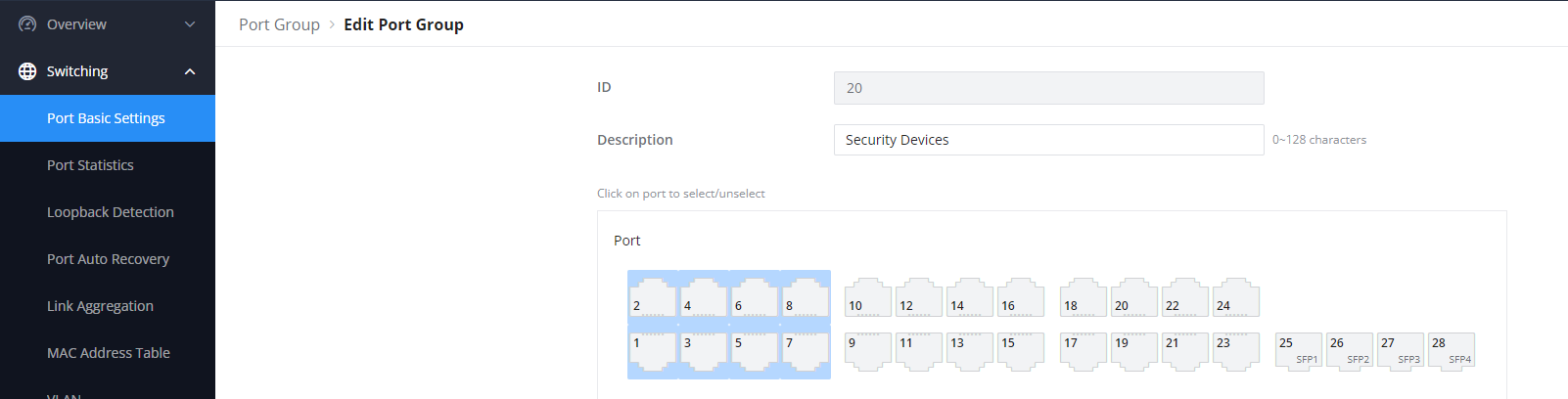
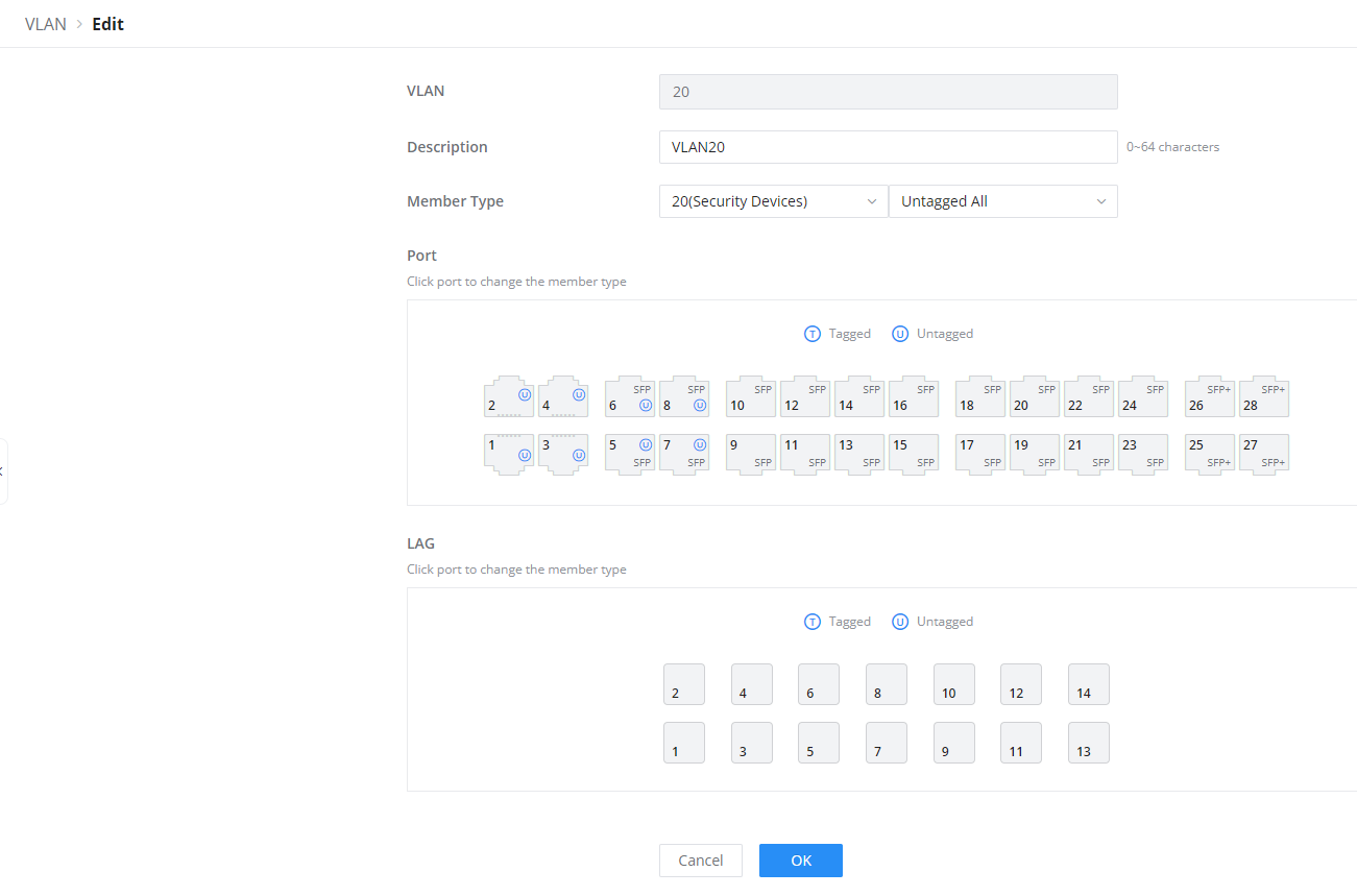
Once the Port Group is created, it can ease up the process of selecting and tagging/untagging VLAN ports individually, Under Switching → VLAN, select the port group to be used for your VLAN
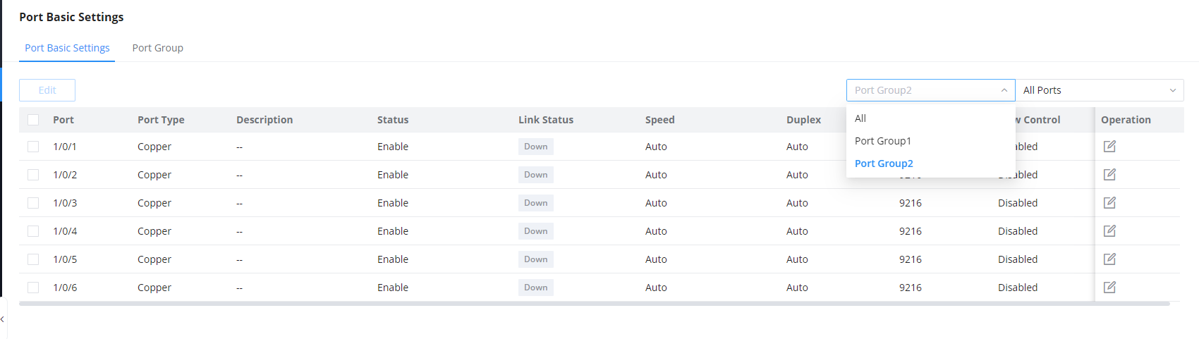
In addition, users can disable/enable specific ports based on the port group created, instead of going through each individual port selection separately:
SFP+ Speed Mode
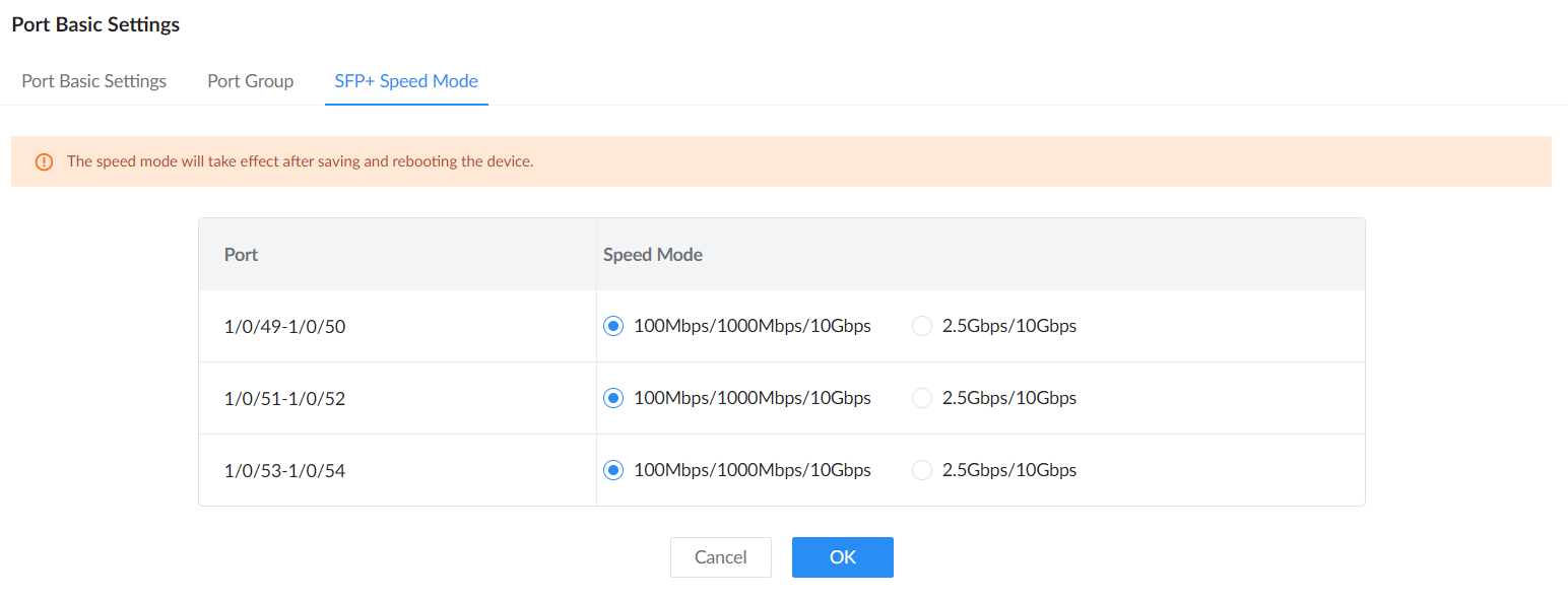
On GWN7806 and GWN7806P, use Switching → Port Basic Settings → SFP+ Speed Mode to select the supported speed combination for each pair of SFP+ ports. To use a 2.5 Gbps SFP+ module, select 2.5Gbps/10Gbps for its port pair, save the configuration, and reboot the switch. Then configure the individual port speed under Port Basic Settings. Plan the reboot during a suitable maintenance window.
Port Statistics
Use Switching → Port Statistics to monitor each port’s transmission and reception rates, utilization, byte and packet counts, and errors. On GWN7806 and GWN7806P, Queue Dropped Packets also reports packets dropped from port queues. Use the port’s Details action for additional statistics. Counters can be cleared for an individual port or with Clear All.
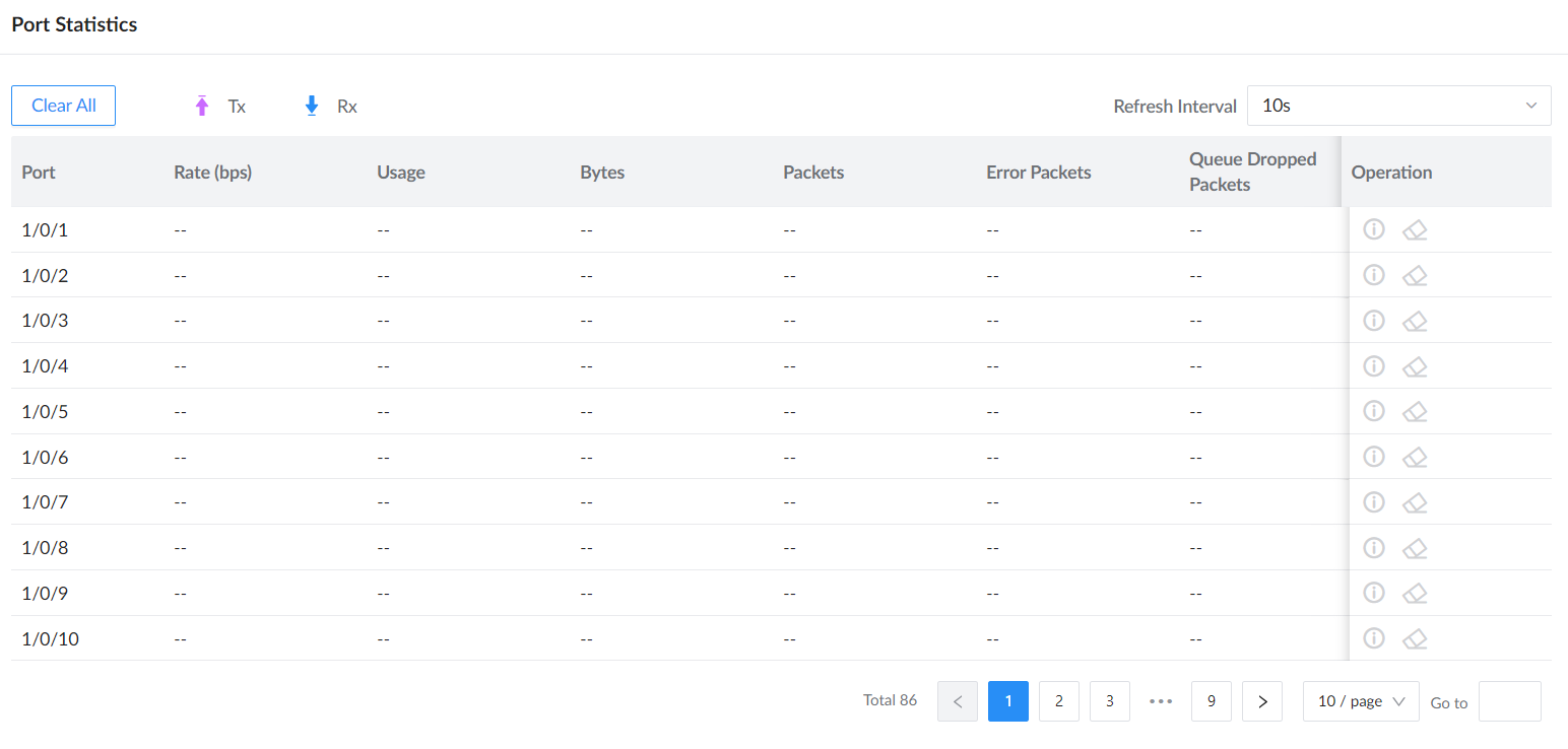
To view even more details like Etherlike (SNMP), RMON, and port Private MIB information.

Loopback Detection
By enabling the loop detection function of the interface, the interface periodically sends detection packets to check whether the packets are returned to the device, and then determines whether there is a loop in the device. If a loop is detected, the port is automatically shut down to eliminate the loop and ensure the normal operation of the network environment.
After enabling Loopback Detection, set Detect Interval (s) to control how often detection packets are sent. The valid range is 1 to 1000 seconds.
After enabling Loopback Detection, set Detect Interval (s) to control how often detection packets are sent. The valid range is 1 to 1000 seconds.

Port Auto Recovery
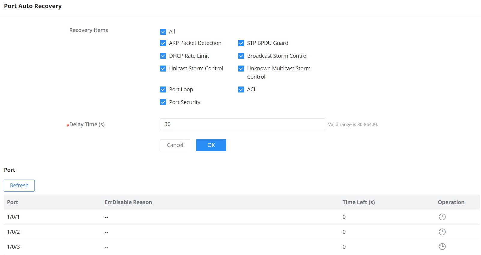
Port Auto Recovery helps recover a port after a specific delay that can be specified by the user. When the following functions of the port trigger the port down, the port automatically returns to the up state after the delay time:
Examples:
- ARP packet detection: If the ARP rate in DAI exceeds the set value, the current port will be shut down.
- STP BPDU Guard: In spanning tree, the port enables BPDU Guard. When this function is triggered, the port will be shut down.
- Port Loop: When the port is self-looping and spanning tree is enabled, the port will be shut down.
- ACL: When the ACL rule is matched and the action is shutdown, the port will be shut down.
- Port Security: When the number of port MAC addresses exceeds the set number, the port will be shut down.
Link Aggregation
LAG means Link Aggregation Group which groups some physical ports together to make a single high-bandwidth data path. Thus it can implement traffic load sharing among the member ports in a group to enhance the connection reliability.
Link Aggregation Group
There are two load balance modes on the GWN780x Switches, either based on the MAC Address or based on the IP – MAC Address. And in terms of the type of LAG, there are either the static option or to use the LACP or Link Aggregation Control Protocol both of them are supported.
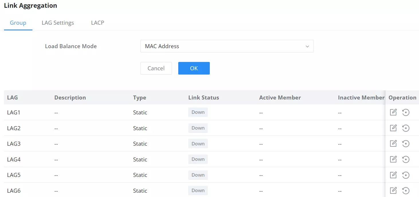
Load Balancing Mode | Select your Load balance mode. MAC address – Aggregated group will balance the traffic based on different MAC addresses. Therefore, the packets from different MAC addresses will be sent to different links. IP/Mac Address – Aggregated group will balance the traffic based on MAC addresses and IP addresses. Therefore, the packets from same MAC addresses but different IP addresses will be sent to different links. |
Edit Group | Name: Enter the name of the LA Group. Type: Use the drop down menu to specify the type for LAG.
GE: Click on port to check / uncheck which ones will be part of this LAG. |
Link Aggregation Port
LAG Port Settings
On this page, the user can Enable the Link Aggregation Group and add a Description as well as specify the speed and the flow control for LAG.
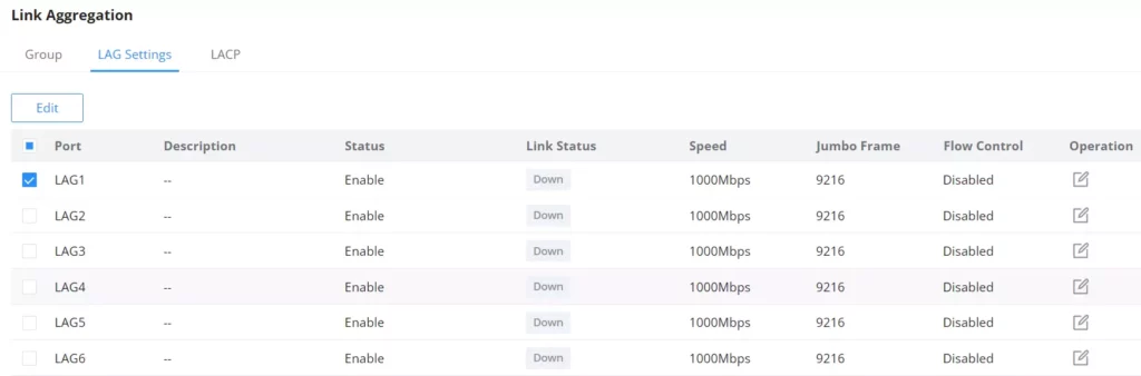
Port | The selected LAG to be configured. |
Description | It is used to configure the information description for this LAG , which can be a description of usage, etc., with a maximum of 128 characters, and the characters limited to input are numbers 0-9 , letters az / AZ and special characters. |
Port Enable | Set whether to enable the interface. it is enabled by default. |
Speed | Set the rate of the interface, the options are {Auto, 10Mbps, 100Mbps, 1000Mbps}. The default is auto-negotiation. Note: When set to Auto, the rate of the interface is automatically negotiated between the interface and the peer port . |
Jumbo Frame | Specify the jumpo frame, valid range is 1518-12288. Default value is 9216 |
Flow Control | Set the flow control on the interface, the options are { Disabled, Enabled, Auto}. The default is Disabled After enabling it, if the local device is congested, it will send a message to the peer device to notify the peer device to temporarily stop sending packets, after receiving the message, the peer device will temporarily stop sending packets to the local and vice versa. Thus, the occurrence of packet loss is avoided. |
Link Aggregation Settings
LACP
LACP or Link Aggregation Control Protocol is based on the priority, and the user can enable a system priority or even specify the the priority for each port individually.
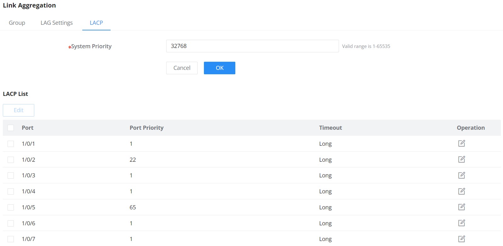
System Priority | Set the system priority of LACP, the value range is an integer from 1-65535, the default is 32768. |
Edit LACP | Port: Select the switch LAG interface to be configured Port Priority:Set the LACP protocol priority of the port , the value range is an integer from 1 to 65535 , the default is 1. Note: The smaller the priority value of the port , the higher the LACP priority of the port. Timeout: Set the timeout time for receiving LACP packets, the options are { Short, Long} , the default is Short.
|
Link Aggregation – LACP
MAC Address Table
The MAC address table records the correspondence between the MAC addresses of other devices learned by the switch and the interfaces, as well as information such as the VLANs to which the interfaces belong. When forwarding a packet, the device queries the MAC address table according to the destination MAC address of the packet. If the MAC address table contains an entry corresponding to the destination MAC address of the packet, it directly forwards the packet through the outbound interface in the entry. If the MAC address table does not contain an entry corresponding to the destination MAC address of the packet , the device will use broadcast mode to forward the packet on all interfaces in the VLAN to which it belongs except the receiving interface.
The entries in the MAC address table are divided into Dynamic Address, Static MAC Address, Black hole Address and Port Security Address.
Dynamic Address
the MAC address table is established based on the automatic learning of the source MAC address in the data frame received by the device. If the MAC address entry does not exist in the MAC address table, the device adds the new MAC address and the interface and VLAN corresponding to the MAC address as a new entry into the MAC address table. GWN780x Switch will update the entry by resetting the aging time.
Aging Time:
Dynamic MAC address entries are not always valid . Each entry has a lifetime. The entries that cannot be updated after reaching the lifetime will be deleted. This lifetime is called the Aging Time. If the record is updated before reaching the lifetime, the aging time of the entry will be recalculated.
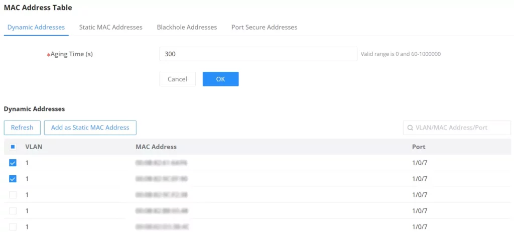
Click on the “Refresh” button to update the table, or click on the “Add Static MAC Address” button to add the entry to the static MAC address.
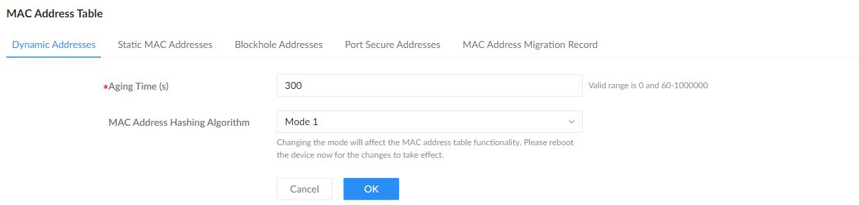
MAC Address Hashing Algorithm selects the mode used for the MAC address table. Open Switching → MAC Address Table → Dynamic Addresses and choose the required mode. Changing this setting affects MAC address table operation and requires a reboot to take effect; schedule the change during a maintenance window.
Static MAC Address
This section allows the user to manually assign a MAC address to the MAC table. The configuration
result will be displayed on the table listed on the lower side of this web page.
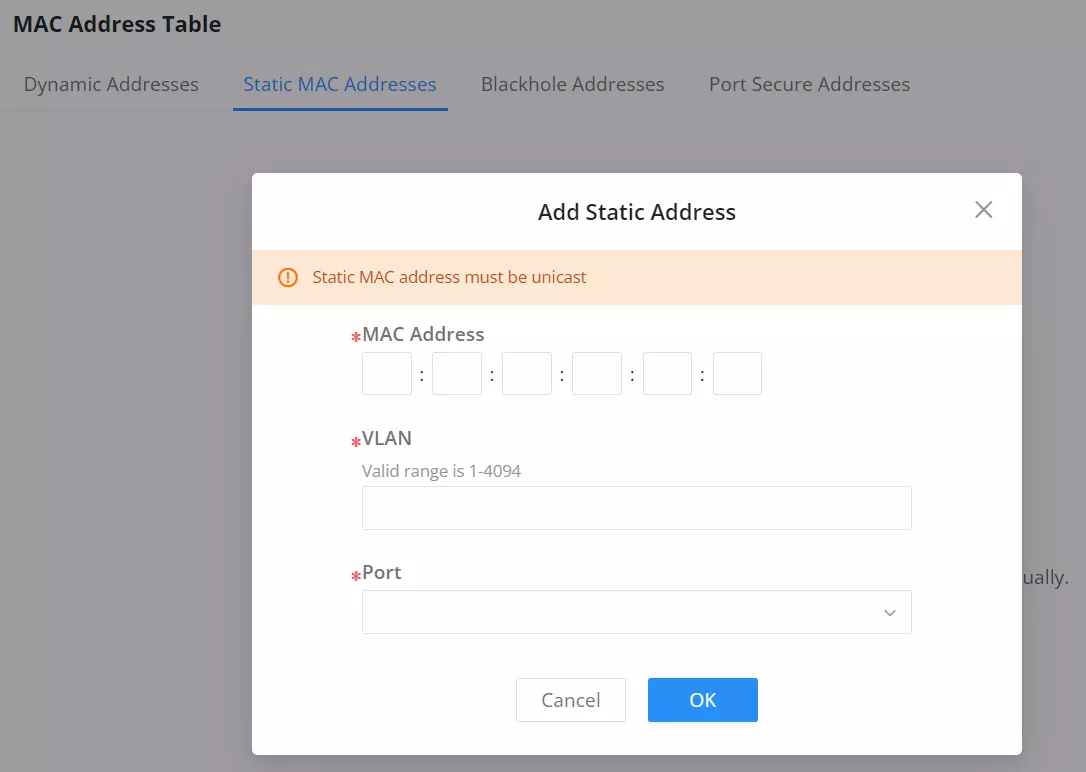
MAC Address | Enter the MAC address that will be forwarded |
VLAN | This is the VLAN group to which the MAC address belongs. |
Port | Select the port where received frame of matched destination |
Static MAC Address
Black Hole Address
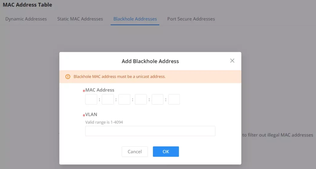
If a MAC address is not trusted or insecure, The user can block the traffic of certain MAC Addresses and discard them by adding them to the Black Hole Address Table.
Click on the “Add” button then enter the MAC Address and the VLAN.
Port Security Address
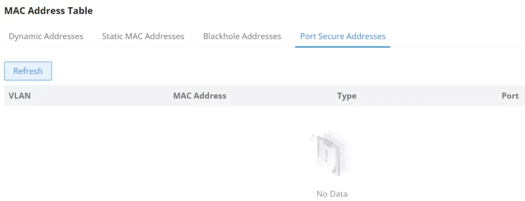
After enabling port security in Security → Port Security, the addresses will be displayed in the MAC Address Table → Port Security Address synchronously.
The list shows the interface name, VLAN, and MAC address.
MAC Address Migration Record
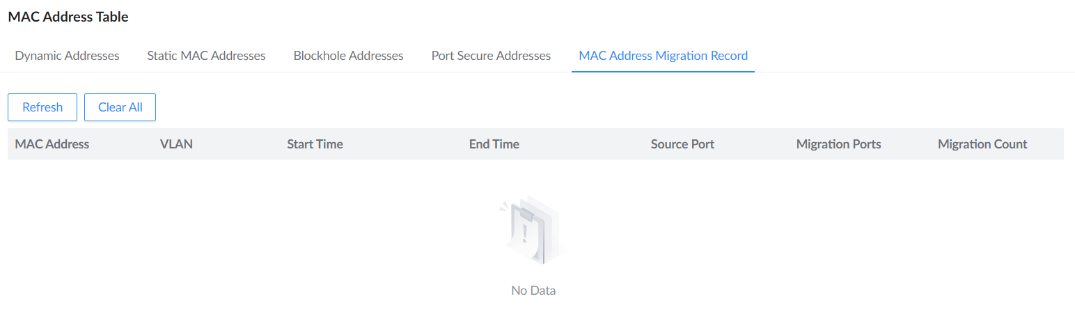
On GWN7806 and GWN7806P, open Switching → MAC Address Table → MAC Address Migration Record to investigate learned MAC addresses moving between ports. Each record identifies the MAC address and VLAN, the source and migration ports, the start and end times, and the migration count. Use Refresh to retrieve the latest records. Clear All removes the recorded history.
VLAN
A virtual local area network, virtual LAN or VLAN, is a group of hosts with a common set of requirements that communicate as if they were attached to the same broadcast domain, regardless of their physical location. A VLAN has the same attributes as a physical local area network (LAN), but it allows for end stations to be grouped together even if they are not located on the same network switch. VLAN membership can be configured through software instead of physically relocating devices or connections.
A user can click on “Add” button to add a new VLAN, also it’s possible to create many VLANs at the same time by specifying a range, for example (7-9) will create VLAN 7,8 and 9, or create different separated VLANs, for example (11,89) will create VLAN 11 and 89.


If the VLAN is already created there is also the option to modify it by clicking on modify button for more options and settings like Description, Tagged and Untagged ports and LAGs.
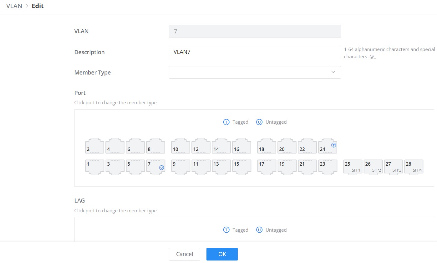
VLAN | The specified VLAN ID |
Description | Enter a brief comment for the VLAN ID. |
Member Type | Select from the drop-down list:
|
GE | Select individually which ports are tagged, untagged or unselected. Note:
|
LAG | Select individually which LAGs are tagged, untagged or unselected. |
Edit VLAN
Please refer to the table below for more details about Tagged and Untagged Ports.
Port Type | Receiving Packets | Forwarding Packets | |
Untagged Packets | Tagged Packets | Tagged Packets | |
Untagged | When untagged packets are received, the port will add the default VLAN tag, i.e. the PVID of the ingress port, to the packets. | If the VID of packet is allowed by the port, the packet will be received. If the VID of packet is forbidden by the port, the packet will be dropped. | The packet will be forwarded after removing its VLAN tag |
Tagged | The packet will be forwarded with its current VLAN tag | ||
VLAN Tagged and Untagged
VLAN Port Settings
The Port Settings page allows for configuring VLAN on each port and LAG by specifying the Link Type (Trunk, Access, Hybrid, or QinQ) as well as the default VLAN or PVID, the user can also enable Ingress Filtering for the selected port, also the accepted Frame Type (All, Tag Only and Untag only) and more.

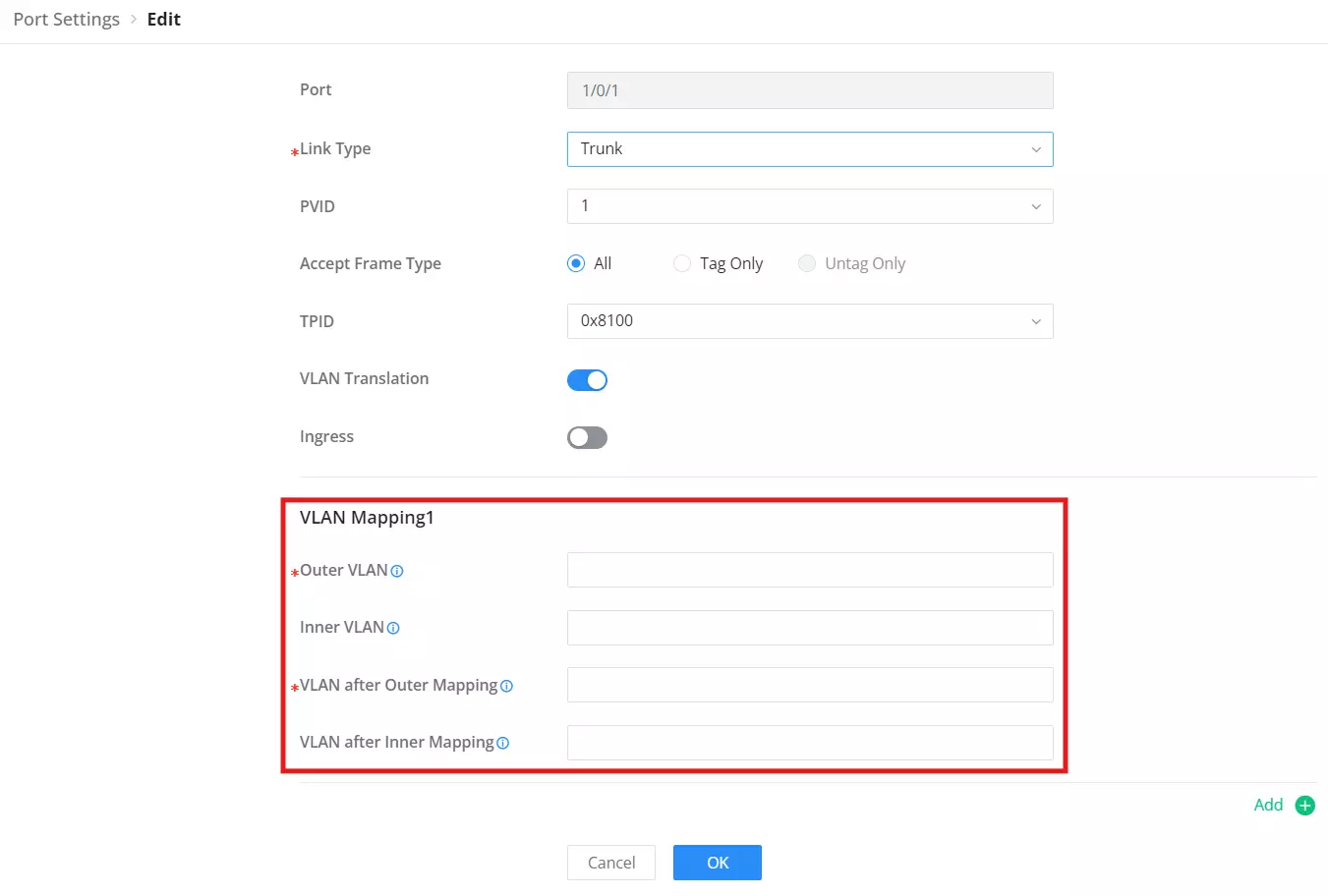

Port | Shows the selected Port. |
Link Type | Select the Link Type:
|
PVID | Enter the default VLAN ID. |
Accept Frame Type | Specifies which types of Ethernet frames are accepted by the port. Options vary depending on the selected Link Type: Hybrid:
Access:
Trunk:
QinQ:
Note: Setting Tag Only is the recommended method to disable native VLAN behavior on trunk and hybrid ports, providing better traffic control and increased security. |
Ingress Filtering | Set whether to enable the inbound filtering function of the interface. Ingress Filtering is only available for Hybrid port, and it’s enabled by default. Note: Ingress filtering is a method used by enterprises and internet service providers (ISPs) to prevent suspicious traffic from entering a network. |
VLAN Translation | Allows translating one VLAN ID to another at the port level. It’s useful for scenarios where different parts of the network use different VLAN IDs but need to communicate with each other. |
MAC VLAN | Allows the switch to assign VLANs based on the MAC address of the incoming traffic. It can be used for more dynamic VLAN assignment, where devices can be automatically placed into specific VLANs based on their MAC addresses. |
Protocol VLAN | Allows VLAN assignments based on the protocol type in the frame, such as IP or ARP. It enables grouping traffic from certain protocols into specific VLANs for easier network management. |
VLAN Port Settings
VLAN Port Members
On this page, the user can define both Tagged and Untagged VLANs (members) for each port individually.

Trunk Allowed VLANs allow the configuration of VLANs that do not yet exist on the switch and are only effective for configured VLANs.


Voice VLAN
A voice VLAN (virtual local area network) is a dedicated VLAN specifically designed to carry voice traffic, such as IP phone calls. By isolating voice traffic from other types of network traffic, voice VLANs help ensure that voice calls are prioritized and experience minimal latency or jitter. This is critical to maintaining clear and uninterrupted voice communications.
Voice VLAN advantages:
- Improved voice quality: By isolating voice traffic from other types of network traffic, voice VLANs help reduce the latency and jitter that can cause choppy or distorted audio during voice calls.
- Reduced congestion: By prioritizing voice traffic, voice VLANs help prevent other types of network traffic from interfering with voice calls, even during periods of heavy network usage.
- Simplified network management: Voice VLANs can simplify network management by making it easier to troubleshoot and resolve voice-related issues.
For example, when an IP phone is connected to a GWN780x switch port, the switch prioritizes traffic in the voice VLAN, ensuring that voice packets are forwarded before other types of packets.
The user can select more than one way to set up the voice VLAN:
- Auto Voice VLAN using LLDP
- Tagged OUI using LLDP
- Tagged OUI using VLAN Tag
- Untagged OUI
For more details, please visit this guide: GWN78xx(P) – Voice VLAN Guide.
To configure Voice VLAN, please navigate to Web UI → Switching → VLAN page → Voice VLAN tab.

OUI
An OUI address is a unique identifier assigned by IEEE (Institute of Electrical and Electronics Engineers) to a device vendor. It comprises the first 24 bits of a MAC address. You can recognize which vendor a device belongs to according to the OUI address. The following table shows the OUI addresses of several manufacturers. There is also the option to add a custom one based on user needs.

The built-in Voice VLAN OUI list includes Grandstream prefixes such as 00:0B:82, C0:74:AD, EC:74:D7, and 14:4C:FF. Review the list before adding a custom vendor prefix.
MAC VLAN
MAC VLAN is a networking technique where each VLAN is based on the source MAC address of incoming frames. Devices with the same MAC address share a VLAN. This segmentation enables isolated communication between devices within the same VLAN based on MAC addresses.
VLANs are divided according to the source MAC address of the data frame. Through the configured MAC address and VLAN mapping table, when the switch receives an untagged frame, it adds the specified VLAN Tag to the data frame based on the mapping table.
To add a MAC address to VLAN mapping, click on “Add” button then specify the MAC Address, Mask Length, VLAN and the priority (802.1p).

Protocol VLAN
VLANs are divided according to the protocol (family) type and encapsulation format to which the data frame belongs. Through the configured protocol domain and VLAN mapping table in the Ethernet frame, when the switch receives an untagged frame, it adds the specified VLAN Tag based on the mapping table.

PVLAN
Within the GWN780x family, Private VLAN (PVLAN) is supported on the GWN7806(P), offering enhanced traffic isolation within the same VLAN domain. This allows more granular segmentation and security, especially useful in shared environments like data centers, hotels, or enterprise access layers.
VLAN Settings
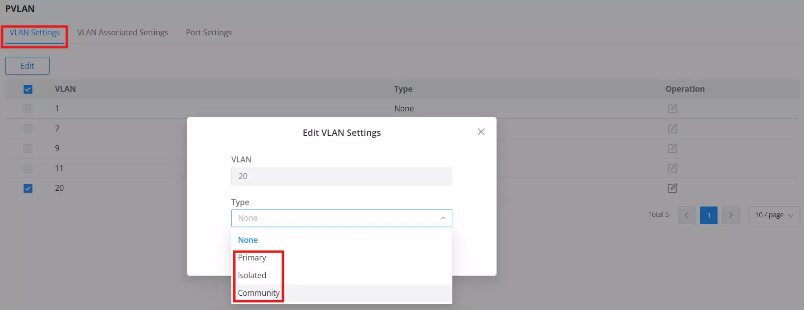
This tab allows assigning a PVLAN type to each VLAN.
- Go to Switching > PVLAN > VLAN Settings.
- Select a VLAN and click Edit.
- Choose the VLAN type from:
- Primary: Communicates with all other PVLAN types.
- Isolated: Can only talk to Primary VLAN.
- Community: Can talk to Primary and other VLANs in the same Community.
- Click OK then Save.
VLAN Associated Settings
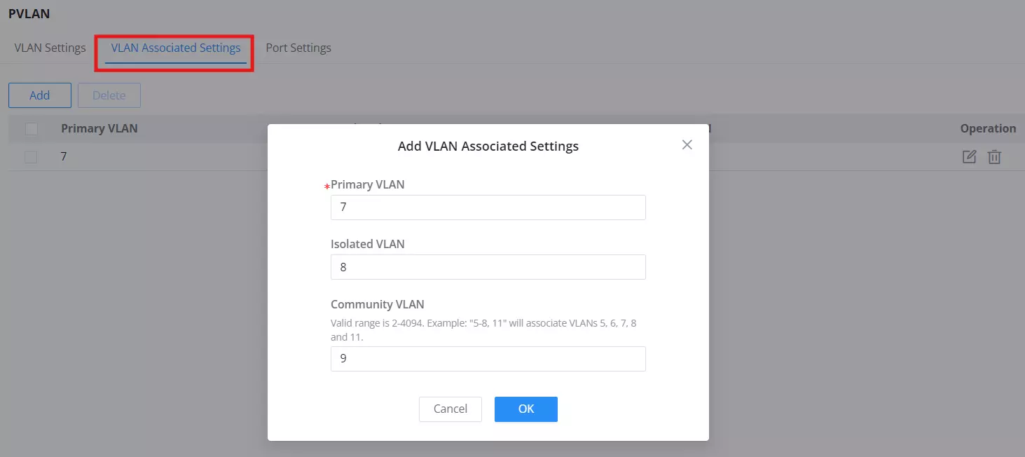
This section allows linking VLANs together in a PVLAN structure.
- Go to Switching > PVLAN > VLAN Associated Settings.
- Click Add, then set:
- Primary VLAN: The main VLAN in this association.
- Isolated VLAN: VLAN(s) that only communicate with the Primary.
- Community VLAN: VLAN(s) that communicate with Primary and each other.
- Use comma-separated lists (e.g.,
11,12) or ranges (20-24) as needed. - Click OK to apply.
Port Settings (PVLAN)
Here you bind switch ports to PVLAN roles.
- Go to Switching > PVLAN > Port Settings.
- Select a port and click Edit.
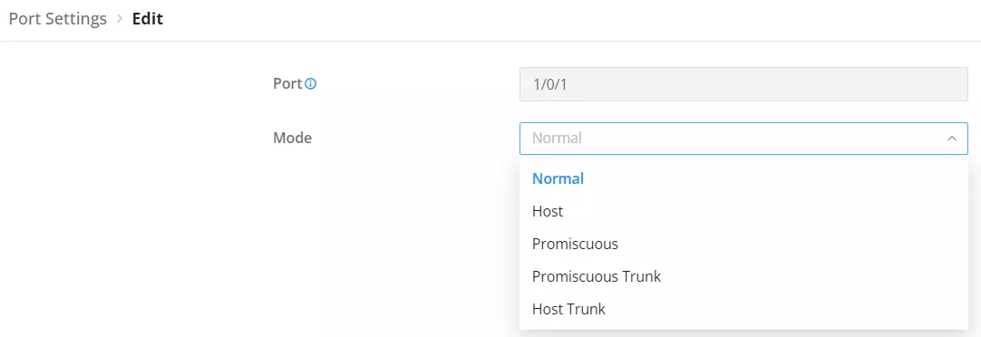
- Choose the Mode:
- Promiscuous: Communicates with all other PVLAN port types.
- Host: Communicates only with Promiscuous ports.
- Community: Communicates with Promiscuous and other Community ports in the same VLAN.
- Trunk Variants: Used to forward tagged PVLAN traffic.
- Click OK and then Save.
Spanning Tree
STP (Spanning Tree Protocol), Devices running STP discover loops in the network and block ports by exchanging information, in that way, a ring network can be disbranched to form a tree-topological ring-free network to prevent packets from being duplicated and forwarded endlessly in the network.
BPDU (Bridge Protocol Data Unit) is the protocol data that STP, RSTP and MSTP use. Enough information is carried in BPDU to ensure the spanning tree generation. STP is to determine the topology of the network via transferring BPDUs between devices.
This page allows a user to configure and display Spanning Tree Protocol (STP) property configuration including the STP Mode (STP, RSTP or MSTP), Path Cost, Bridge Priority, Max Hops, Hello and Max Aging time and Forward Delay Time.
On MST Instance, set the Region Name and Revision Level. The instance table identifies each MSTI and its associated VLANs, priority, bridge information, root port, path cost, and remaining hops.
On MST Instance, set the Region Name and Revision Level. The instance table identifies each MSTI and its associated VLANs, priority, bridge information, root port, path cost, and remaining hops.
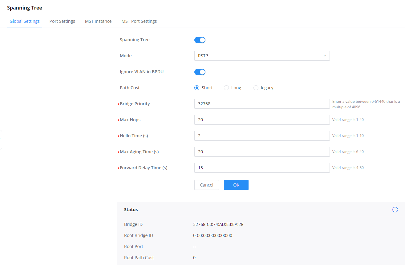
Spanning Tree | Set whether to enable Spanning Tree. |
Mode | Set the operating mode of Spanning Tree (STP).
|
Ignore VLAN in BPDU | This feature allows the switch to ignore VLAN-specific information in Bridge Protocol Data Units (BPDUs). This prevents VLAN configurations from influencing Spanning Tree Protocol (STP) decisions across multiple VLANs. |
Path Cost | Specify the path cost method (Short, Long, or Legacy). Default is Short. |
Bridge Priority | Select the Bridge Priority, In an STP network, the device with the smallest bridge ID is elected as the root bridge. Default is 32768. Note: The valid range is 0~61440, which must be a multiple of 4096 |
Max Hops | Select the Max Hops (the range is 1 – 40). Default is 20 |
Hello Time (s) | Specify the Hello Time in seconds (the range is 1 -10). Default is 2. Note: The time interval at which the device running the STP protocol sends the configuration message BPDU , which is used by the device to detect whether the link is faulty. |
Max Aging Time (s) | Select The aging time of BPDU packets of the port (the range is 6 – 40). Default is 20. |
Forward Delay Time (s) | Specify the Forward Delay Time in seconds (the range is 4 -30). Default is 15. |
STP Global Settings
STP Port Settings
To configure STP on each port and LAG then navigate to WEB UI → Spanning Tree → Port Settings, then click on “Edit” button.
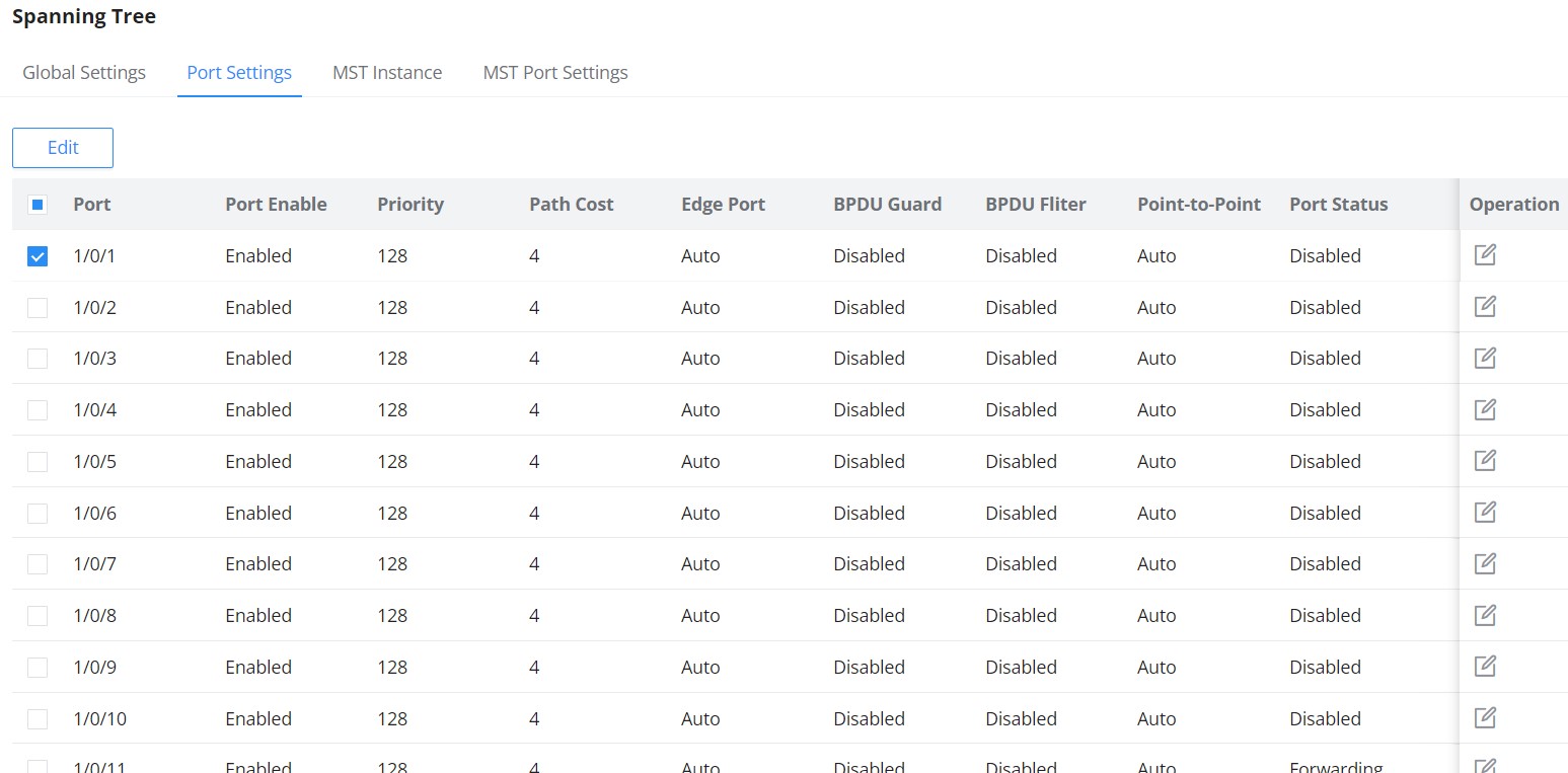
For each port or LAG, the user can enable STP and specify the priority, Path Cost, Edge port, BPDU Guard and Filter and Point-To-Point.
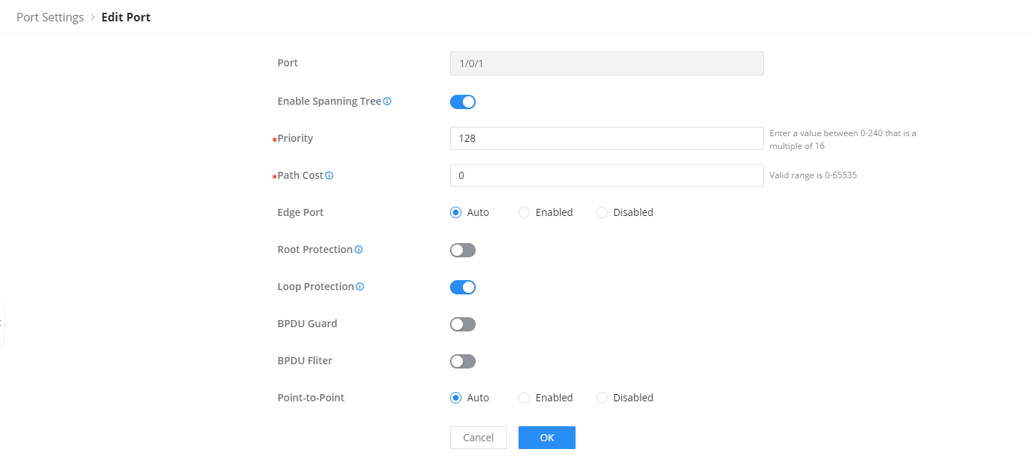
Port | Displays the selected GE/LAG Port. |
Enable STP | Set whether to enable STP on this port. |
Priority | Priority is an important basis for determining whether the port will be selected as the root port. The port with higher priority under the same conditions will be selected as the root port . The smaller the value , the higher the priority . An integer in the range of 0-240, with a step size of 16, and a default of 128 . Note: The valid range is 0~240, which must be a multiple of 16 |
Path Cost | Set the path cost of the port on the specified spanning tree. The default value is 0, which means that path cost calculation is performed automatically. Note:The valid range of path cost depends on the path cost settings in Global Settings.If set to “Short” in Global Settings, the valid range is 0-65535; if set to “Long”, the valid range is 0-200000000; if set to “legacy”, the valid range is 0-200000. |
Edge Port | Set whether to enable Edge Port or disable it, by default it’s on auto. Notes:
|
Root Protection | Safeguards the root bridge by preventing designated ports from becoming the root port, thus protecting the current root bridge from being displaced by lower-priority BPDUs. |
Loop Protection | Prevents Layer 2 loops by ensuring a blocking state on ports that stop receiving BPDUs, avoiding the formation of network loops. |
BPDU Guard | Set whether to enable BPDU Guard. Note: BPDU Guard further protects your switch by turning this port into error state and shutdown if any BPDU received from this port. |
BPDU Filter | Set whether to enable BPDU Filter. Note: Drop all BPDU packets and no BPDU will be sent. |
Point-to-Point | Select Point-to-Point option (Auto, Enabled or Disabled). Default is Auto. Note: determines the STP of link type for this port automatically if set to Auto. |
STP Port Settings
Multiple Spanning Tree Instances
MST or Multiple Spanning Tree Instance allows traffic of different VLAN to be mapped into different MST Instances. GWN780x Switch supports up to 16 independent MST instances (0~15) where each instance can be associated with many VLANs.
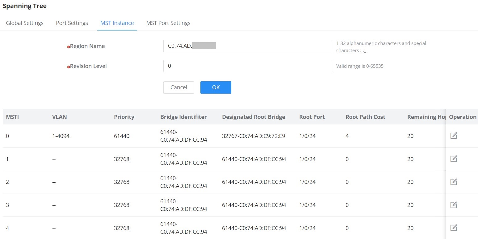
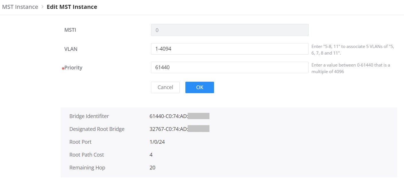
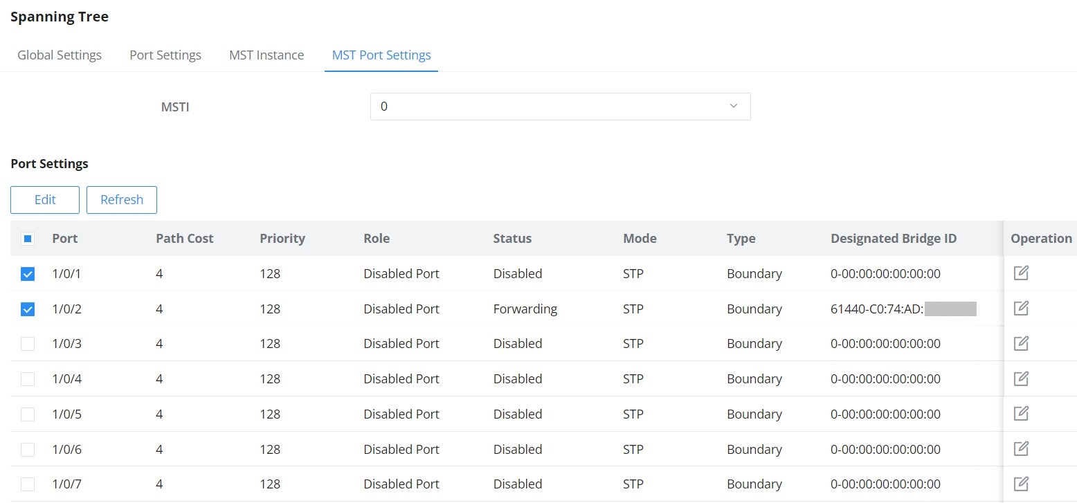
MST Port Settings is used to configure the GE port / LAG group settings for each MST instance.
The table displays the MST parameters for each port.
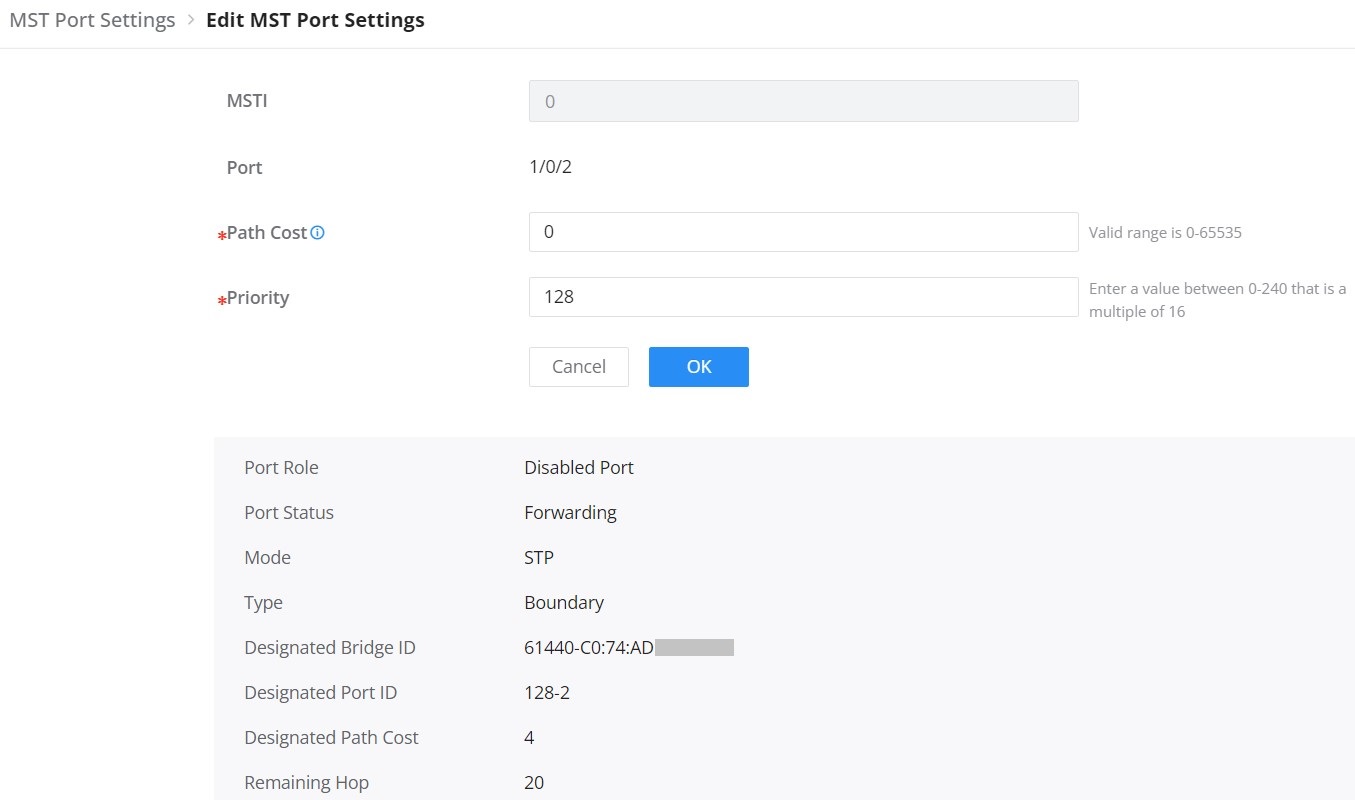
Click on “Edit” button to edit the MST Port Settings for each Port/LAG individually and also the user can even specify the Path Cost and Priority per Port/LAG as well.
PVST VLAN Settings
When Per VLAN Spanning tree protocol is selected as the STP protocol to be used, then the VLAN settings can be defined.
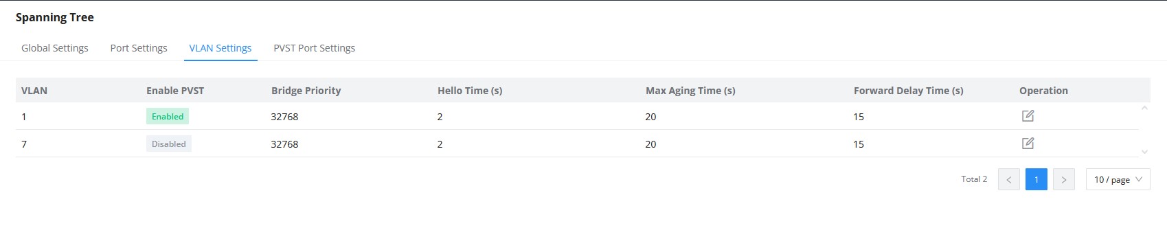
The below parameters are to be configured:
VLAN | Disaplays the VLAN on which the PVST rule will PVST protocol will be applied |
Enable PVST | Enables/disables PVST per VLAN |
Bridge Priority | Defines the bridge priority for the VLAN, valid range is 0-61440, default value is 32768. |
Hello Time (s) | Specify the Hello Time in seconds (the range is 1 -10). Default is 2. |
Max Aging Time (s) | Select The aging time of BPDU packets of the port (the range is 6 – 40). Default is 20. |
Forward Delay Time (s) | Specify the Forward Delay Time in seconds (the range is 4 -30). Default is 15. |
PVST Port Settings
The PVST Port settings defines the priority and path cost for each port of the switch , per each vlan,
It also displays, for each port, its role, designated Bridge ID, designated Port ID, and designated Path Cost.
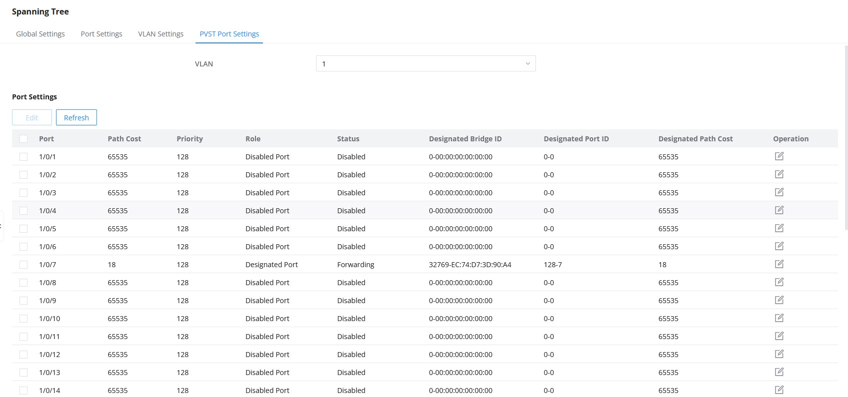
The parameters to be defined are
Port | Displays the port, or ports that the settings will be applied on. |
Priority | Displays the single port priority. valid range is 0-240 and the default value is 18. |
Path Cost | Configures the port path cost for the port on the specified spanning tree. The value must be an integer between 0-65535. The default value is 0, which means the path cost calculation will be performed automatically. |
IP
VLAN IP Interface
Hosts in different VLANs cannot communicate directly and need to be forwarded through routers or layer 3 switching protocols.
A VLAN interface is a virtual interface in Layer 3 mode and is mainly used to implement Layer 3 communication between VLANs, it does not exist on the device as a physical entity. Each VLAN corresponds to an interface by configuring an IP address for it, it can be used as the gateway address of each port in the VLAN so that packets between different VLANs can be forwarded to each other on Layer 3 routing through the VLAN interfaces. GWN switches support IPv4 interfaces as well as IPv6.
IPv4/IPv6 Interface
To add an IP Interface, please click on the “Add” button, refer to the figure below:
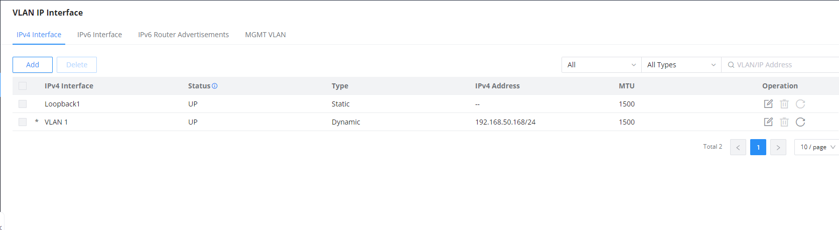
Use the “refresh icon” to request a new IP address from the DHCP server. This action will prompt a confirmation dialog; clicking “OK” will obtain a new IP address, which may change upon successful retrieval.

IPv4 Address Type
To configure an existing IPv4 interface, open its edit action and select Static IP or DHCP. The available fields change with the selected address type.
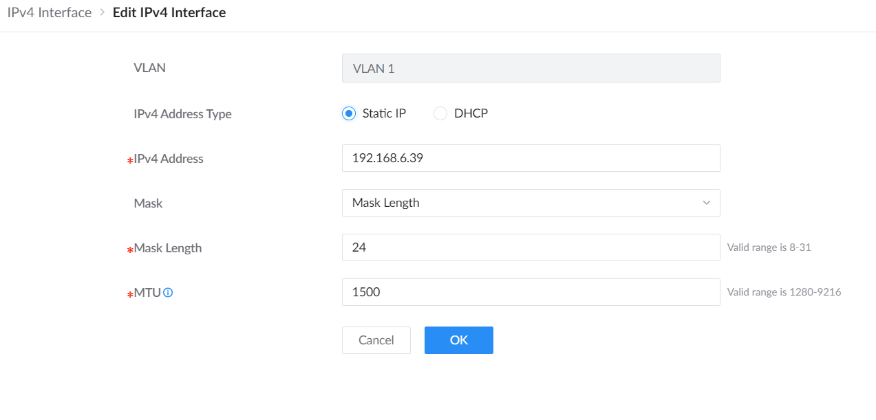
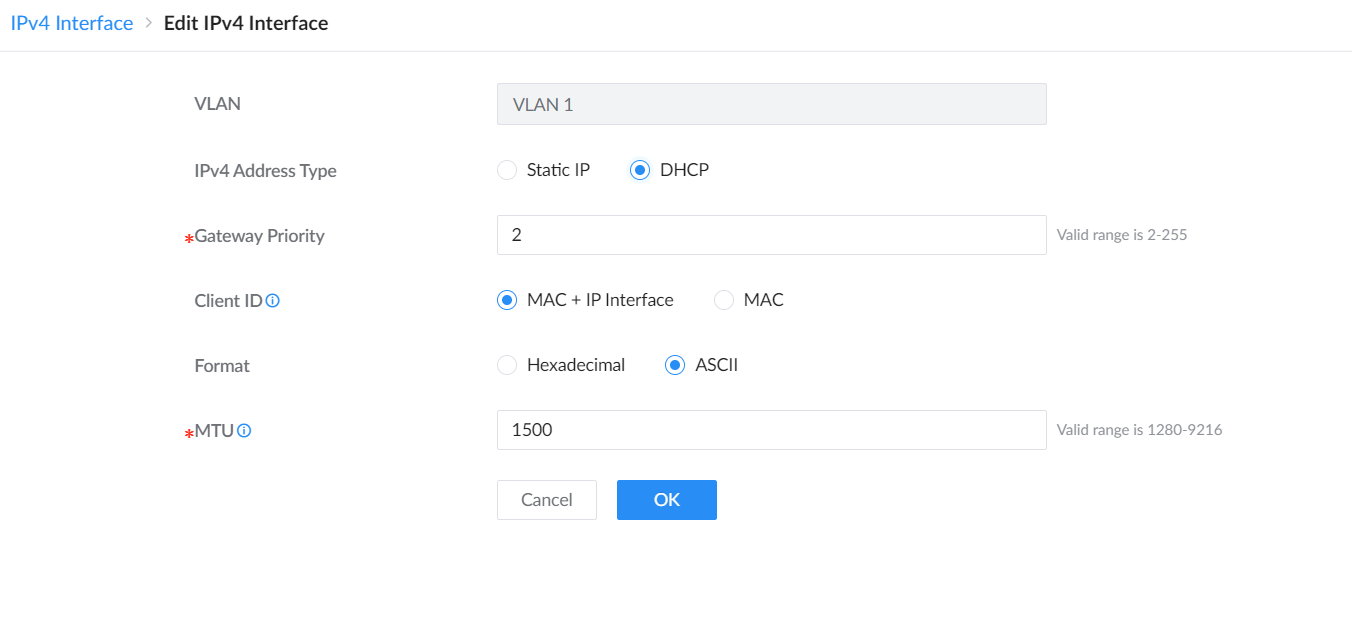
| IPv4 Address Type | Choose Static IP to configure the address manually, or DHCP to obtain IPv4 settings from a DHCP server. |
|---|---|
| IPv4 Address | For Static IP, enter the IPv4 address assigned to the interface. |
| Mask / Mask Length | For Static IP, select the mask format and enter the mask length. The displayed valid range is 8 to 31. |
| Gateway Priority | For DHCP, set the gateway priority from 2 to 255. A smaller value has higher priority. |
| Client ID | For DHCP, choose MAC + IP Interface or MAC to identify the DHCP client request. |
| Format | For DHCP, choose Hexadecimal or ASCII for the Client ID format. |
| MTU | Set the Maximum Transmission Unit from 1280 to 9216 bytes. |
IPv6 Interface
Use the IPv6 Interface tab to enable IPv6 and configure link-local and global unicast addressing, gateway priority, and MTU.

IPv6 Router Advertisements
IPv6 Router Advertisements (RAs) are messages sent by routers to provide information to devices on the network, such as the default gateway, DNS servers, and network prefixes. These advertisements help devices configure their IP addresses and routing automatically without the need for manual configuration. In the VLAN IP Interface section, you can configure RAs for each VLAN to manage IPv6 network settings.

In the Edit IPv6 Router Advertisements screen, you can customize settings for a specific VLAN. This includes enabling or disabling the interface, setting route information, and configuring timeouts and lifetimes for the advertisements. You can also define IPv6 addresses and prefixes, adjust flags for additional configurations, and set the priority of the default route. This allows for fine-tuning the behavior of the advertisements to suit your network requirements.

MGMT VLAN
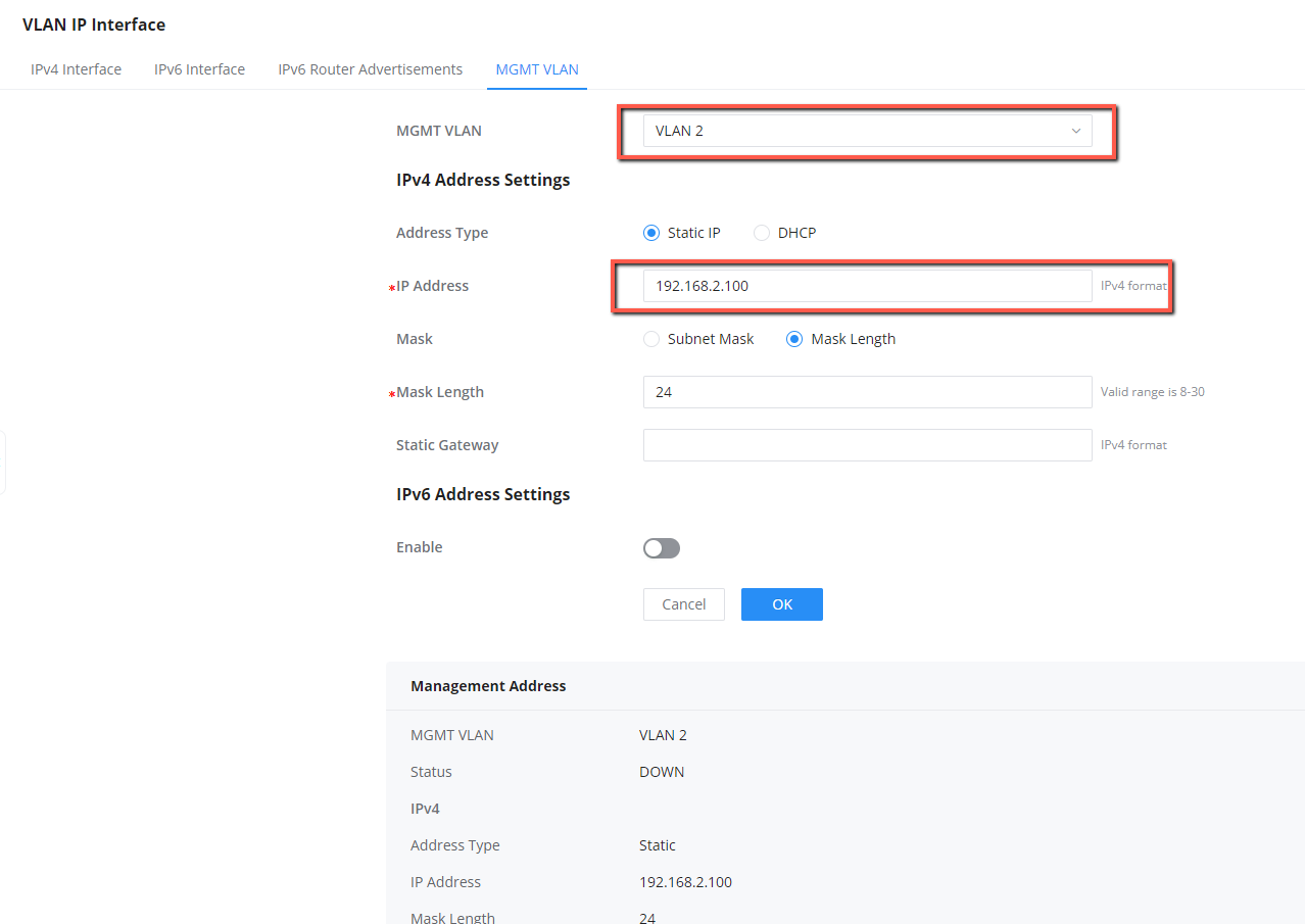
When you assign an IP address to the management VLAN interface, the system synchronizes this IP configuration with the corresponding VLAN interface in the device’s Layer 3 IP interface configuration. This ensures that the IP address used for managing the device is consistent with the VLAN’s routing and switching setup.
For example, if you configure the management VLAN with an IP address 192.168.2.100 on VLAN 2, this IP will also be reflected in the IP interface configuration for VLAN 2, ensuring both management and routing functions are aligned.
Management IP Interface
Use IP → IP Interface → Management IP Interface to select the management VLAN and configure its IPv4 and IPv6 addressing. CoS sets the Class of Service priority for management traffic. Choose a value that matches the network’s QoS policy. Changing the management interface or addressing can interrupt the current management connection.
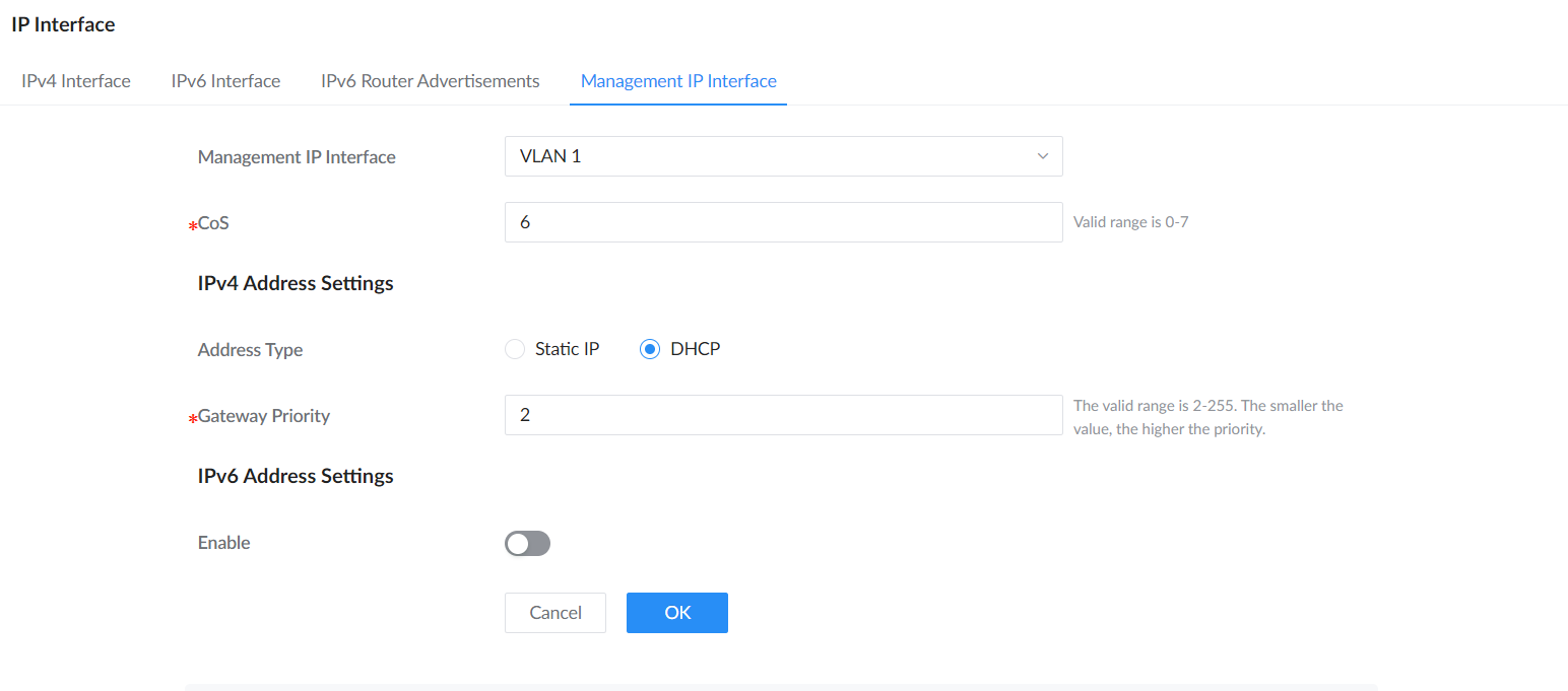
| Management IP Interface | Select the VLAN interface used for switch management. |
|---|---|
| CoS | Set the management traffic priority from 0 to 7. |
| IPv4 Address Settings | Choose DHCP to obtain an address automatically, or Static IP to configure the management address manually. Gateway Priority determines preference when multiple gateways are available; a smaller value has higher priority. |
| IPv6 Address Settings | Enable IPv6 when required and configure the addressing options shown for the selected mode. |
DHCP Server
The DHCP server assigns IPv4 addresses and network settings to clients. Open IP → DHCP Server, enable DHCP Service, and configure the required address pools. Each pool can be enabled or disabled independently. Coordinate the pools with the network’s existing DHCP service to avoid conflicting address assignments.
On the Address Table tab, use the IPv4 Address/Client Name/Client MAC Address field to filter leases.
Under Address Pool Settings, click Add. Choose Global to define the IP Pool Subnet and Mask Length, or choose Interface to select an Interface and enter the starting and ending addresses in IPv4 Pool. Configure the gateway, lease duration, DNS or WINS servers, NetBIOS node type, and DHCP options, then save the pool when ready.
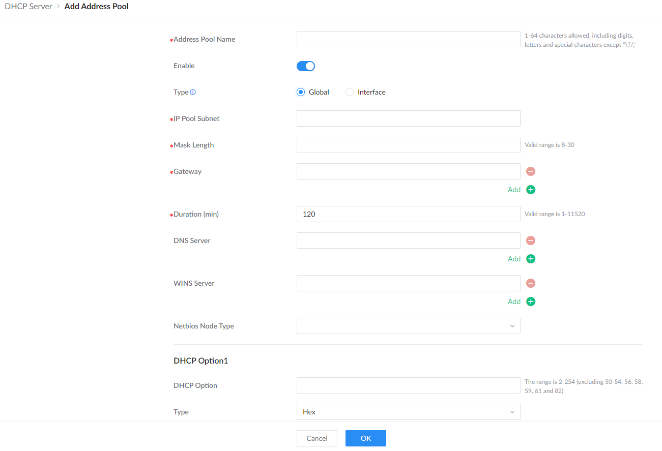
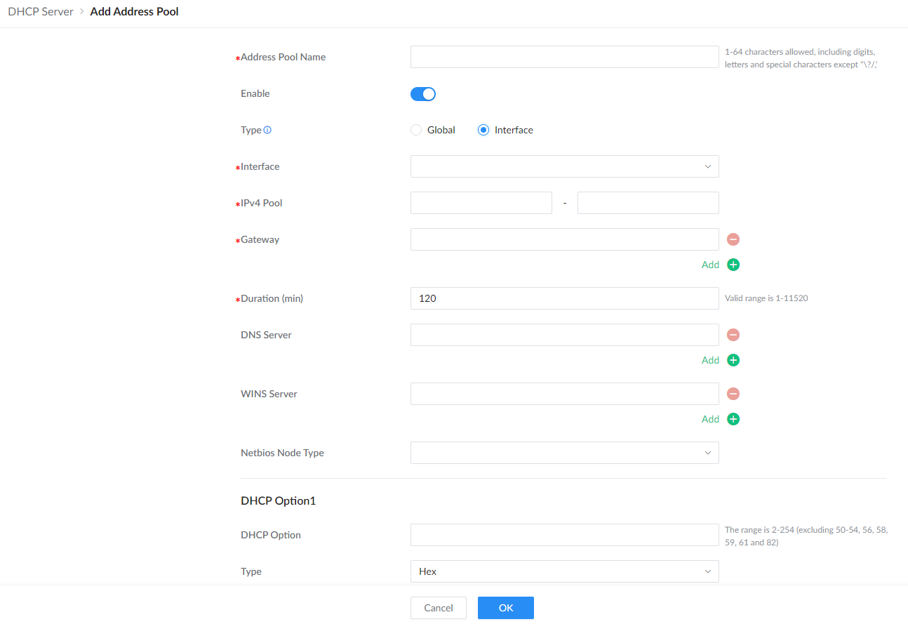
| Address Pool Name | Enter a descriptive name for the pool. |
|---|---|
| Enable | Enable or disable this address pool independently of other pools. The global DHCP service must also be enabled to serve clients. |
| Type | Choose Global to define a subnet-based pool, or Interface to bind an address range to an existing interface. |
| IP Pool Subnet / Mask Length | For the Global type, enter the network address and prefix length used by the pool. |
| Interface / IPv4 Pool | For the Interface type, select the interface and enter the starting and ending IPv4 addresses assigned by the pool. |
| Gateway | Enter the gateway address offered to clients. Use Add for additional gateway entries. |
| Duration (min) | Set the DHCP lease duration in minutes. |
| DNS Server / WINS Server | Enter the servers clients should use. Add additional entries as required. |
| Netbios Node Type | Select the NetBIOS node type when the client environment requires it. |
| DHCP Option / Type / Option Content | Enter the DHCP option code, select the content type (Hex, ASCII, or IP Address), and enter the corresponding Option Content. Hex content must contain an even number of characters. Use Add to define additional options. |
| Service | For option 43, select the service or Custom and supply the corresponding vendor-specific content. |
The address table will displays the hosts (devices) MAC Addresses and the IP addresses when using the DHCP Server. Also it’s possible make a entry a static one by clicking on “Add as Static Binding IP” button.

DHCP Relay
DHCP relay on GWN780x switch helps a network device pass DHCP messages between clients and servers that are on a completely different networks. When you have a DHCP server that needs to serve clients on different subnets (or VLANs). A DHCP relay agent is a network device that can route between the client’s subnet and the server’s subnet. The relay agent gets the broadcast request from the client and sends it to the server, putting its own interface address as the gateway address (giaddr) field in the packet. This way, the server can tell which subnet the client is on and assign a suitable IP address. The server then sends the reply back to the relay agent, which passes it to the client.
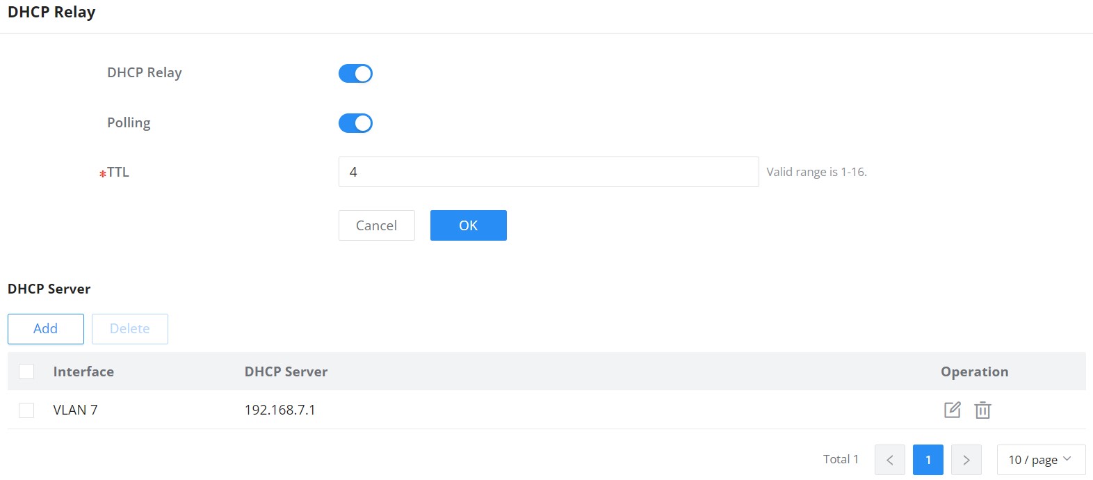
DHCP Relay | Set whether to enable the global DHCP relay function the default is off. |
Polling | Set whether to enable the polling function of the DHCP relay disabled by default. |
TTL | Set the TTL value of the DHCP request message after being forwarded by the DHCP relay layer 3. the value is an integer from 1 to 16 , and the default is 4 . |
DHCP Server | |
Interface | Select from the existing VLAN interfaces. |
DHCP Server | Set the address of the DHCP server. Note: The DHCP server address cannot be the interface IP address of the DHCP relay gateway , otherwise the DHCP client cannot obtain an IP address. |
DHCP Relay
ARP Table
Address Resolution Protocol (ARP) resolves IPv4 addresses to MAC addresses on the local network. The switch keeps learned mappings in its ARP table and lets administrators create fixed mappings when an address relationship must remain unchanged.
| Entry type | How it is created | Lifecycle and use |
|---|---|---|
| Dynamic | Learned automatically from ARP traffic. | Can be updated by new ARP information and is removed when its aging timer expires. Use dynamic entries for normal host discovery. |
| Static | Created by an administrator or converted from a learned entry. | Does not age out. Use a static entry when the switch must keep a fixed IPv4-to-MAC mapping. |
To configure ARP, navigate to Web UI → IP → ARP Table.
View ARP entries
The ARP Table is the switch’s current list of IPv4-to-MAC address mappings. The switch consults these mappings when forwarding IPv4 traffic on the local network so that it can place the correct destination MAC address in each Ethernet frame. Each row identifies the host’s IP address and MAC address, the IP interface and physical port through which it is reachable, whether the mapping is dynamic or static, and the remaining lifetime of a dynamic entry. Use the type selector or the IP Interface/IP Address/MAC Address/Interface search field to narrow the list.
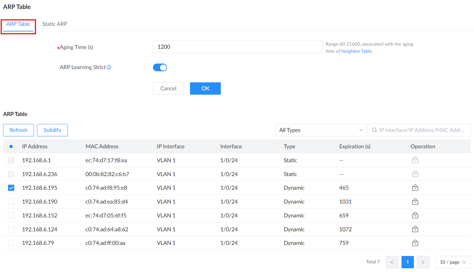
| Control | Description |
|---|---|
| Aging Time (s) | Sets how long a dynamic ARP entry remains before aging out. The valid range is 60 to 21600 seconds. This value is associated with the Neighbor Table aging time. |
| ARP Learning Strict | When enabled, the switch learns an ARP entry only from an ARP reply that matches an ARP request sent by the switch. This helps reduce ARP spoofing and poisoning attempts. |
| Refresh | Retrieves the latest ARP entries. |
| Solidify | Converts the selected learned entry into a static mapping. |
| All Types | Filters the list by entry type. |
| Search | Filters entries by IP interface, IP address, MAC address, or physical interface. |
Static ARP tab
The Static ARP tab manages administrator-configured mappings. Use Add to create a mapping manually. Use the row actions to edit or delete one mapping, or use Delete and Delete All for selected or all mappings. Change a static entry only when you intend to alter address resolution for the affected host.
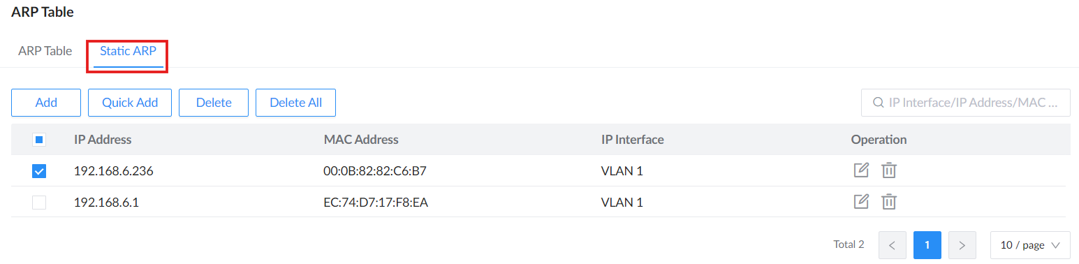
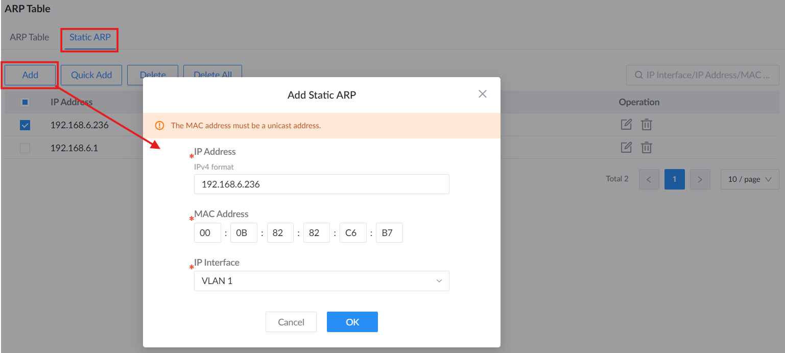
| Field | Description |
|---|---|
| IP Address | Enter the IPv4 address for the mapping. |
| MAC Address | Enter the host’s unicast MAC address. |
| IP Interface | Select the Layer 3 interface on which the mapping applies. |
Quick Add
Click Quick Add to open the list of learned ARP entries. Select one or more entries, then click OK to create static mappings from them. The IP address search field can be used to locate a learned entry before selection.
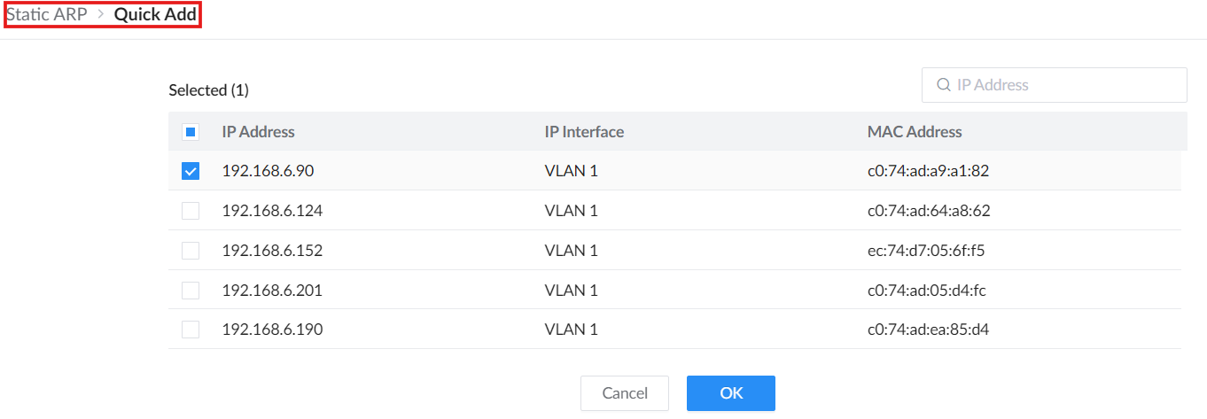
Solidify and Quick Add both create static mappings from learned entries. Use Solidify for a selected entry in the ARP Table, or Quick Add when you want to review learned entries in a dedicated selection view.
Neighbor Discovery
Neighbor Discovery Protocol (NDP) is an important basic protocol in the IPv6 protocol system it replaces the ARP and ICMP router discovery of IPv4. It defines the use of ICMPv6 packets to achieve address resolution, neighbor unreachability detection, duplicate address detection, router discovery, redirection, ND proxy, and other functions.
IPv6 address auto-configuration and router discovery rely on two kinds of ICMPv6 messages: RS (Router Solicitation) and RA (Router Advertisement). Hosts send RS messages to ask routers on the same link to send RA messages right away. Routers send RA messages to let hosts know they are there and give them information like IPv6 prefixes, hop limit, MTU, and configuration flags.
To configure ND please navigate to Web UI → IP → Neighbor Discovery.
The Neighbor Table displays effective IPv6 neighbor entries. Its Aging Time (s) is associated with the ARP Table aging time. Use Refresh to retrieve current entries or Solidify to retain a learned mapping as a static entry.
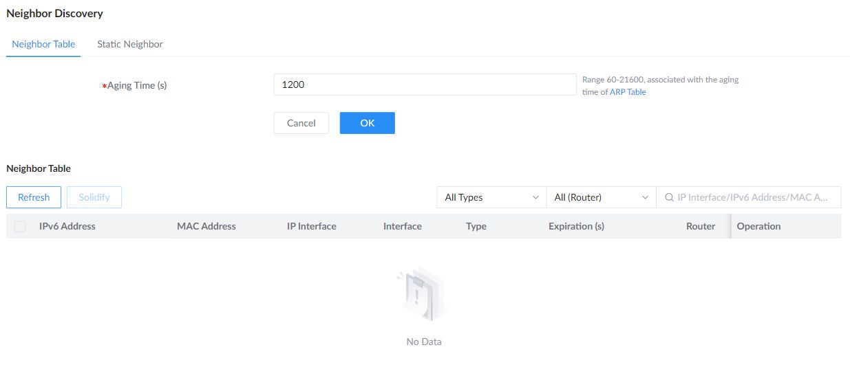
Open Static Neighbor and click Add to configure an IPv6 Address, a unicast MAC Address, and the IP Interface.
| IP Address / IPv6 Address | Enter the host address for the ARP or neighbor mapping. |
|---|---|
| MAC Address | Enter the corresponding unicast MAC address. |
| IP Interface | Select the VLAN IP interface associated with the host. |
DNS
Domain Name System DNS provides translation services between domain names and IP addresses. GWN780x Switches act as a DNS client. When users perform certain applications on the device (such as Telnet to a device or host), they can directly use a memorable and meaningful domain name, and resolve the domain name to the correct address through the domain name system.
DNS domain name resolution is divided into static domain name resolution and dynamic domain name resolution which can be used together when parsing domain names. If the static domain name resolution is unsuccessful, then dynamic domain name resolution will be used, since dynamic domain name resolution may take a certain amount of time and requires the cooperation of the domain name server, some commonly used domain names can be put into the static domain name resolution table, which can greatly improve the effect of domain name resolution.
Global Settings
On this page, the user can designate the switch as a DNS client to resolve DNS names to IP addresses through one or more configured DNS servers. It’s enabled by default.
To configure DNS on GWN780x switches, navigate to Web UI → IP → DNS, then click on the Global Settings tab.
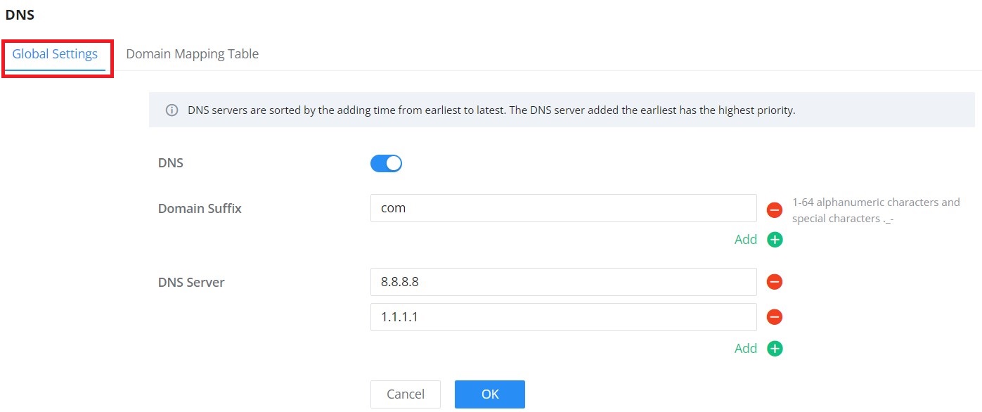
Up to 8 Domain Suffixes and 8 DNS Servers can be added. To add a Domain Suffex or DNS Server click on “+” icon and to delete click on “–” icon.
Domain Mapping Table
To add a static DNS or to view the Dynamic ones, click on the Domain Mapping Table tab.
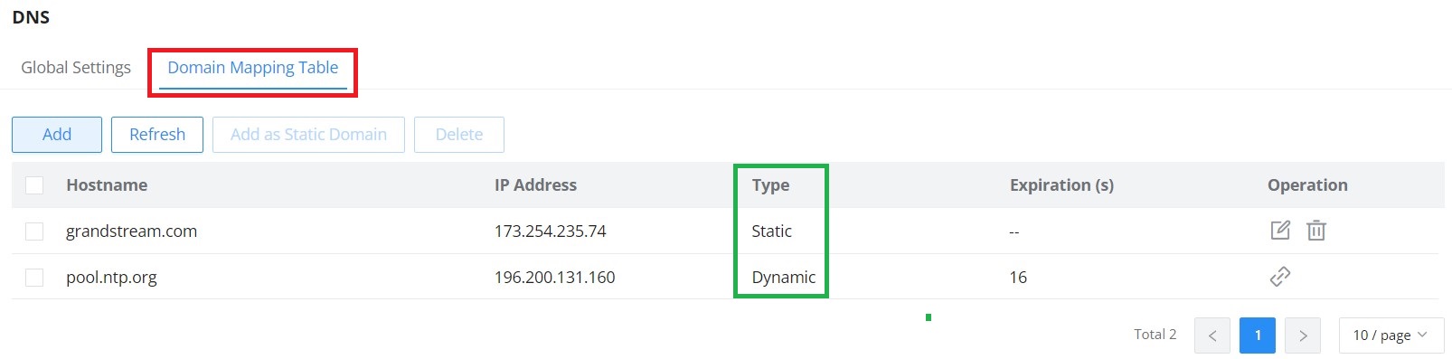
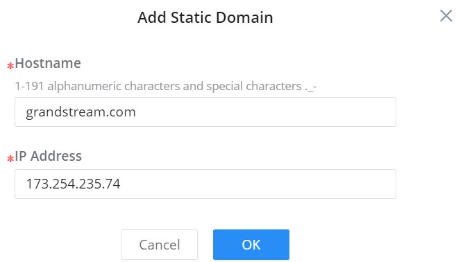
Click on “Add” button to add a new static DNS entry.
The user can also select the dynamic domains and then click on “Add as a static domain” button or icon to make them as static ones.
MULTICAST
IP multicast is a technique for one-to-many communication over an IP infrastructure in a network. To avoid the incoming data broadcasting to all GE/LAG ports, multicast is useful to transfer the data/message to specified GE/LAG ports for IGMP snooping or MLD Snooping. When the Switch receives a message “subscribed” by the client, it must decide to transfer the data to specified GE/LAG ports according to the location of the client (subscribed member).
IGMP Snooping
As an IPv4 Layer 2 multicast protocol, IGMP snooping is the process of listening to Internet Group Management Protocol (IGMP) network traffic. The feature allows a network switch to listen in on the IGMP conversation between hosts and routers. By listening to these conversations the switch maintains a map of which links need which IP multicast streams. Multicasts may be filtered from the links which do not need them and thus controls which ports receive specific multicast traffic.
IGMP Snooping Global Settings
This page allows the user to enable/disable IGMP Snooping function, select snooping version, and enable/disable snooping report suppression also select the Multicast Forward Mode and what to do with Unknown Multicast Packet.
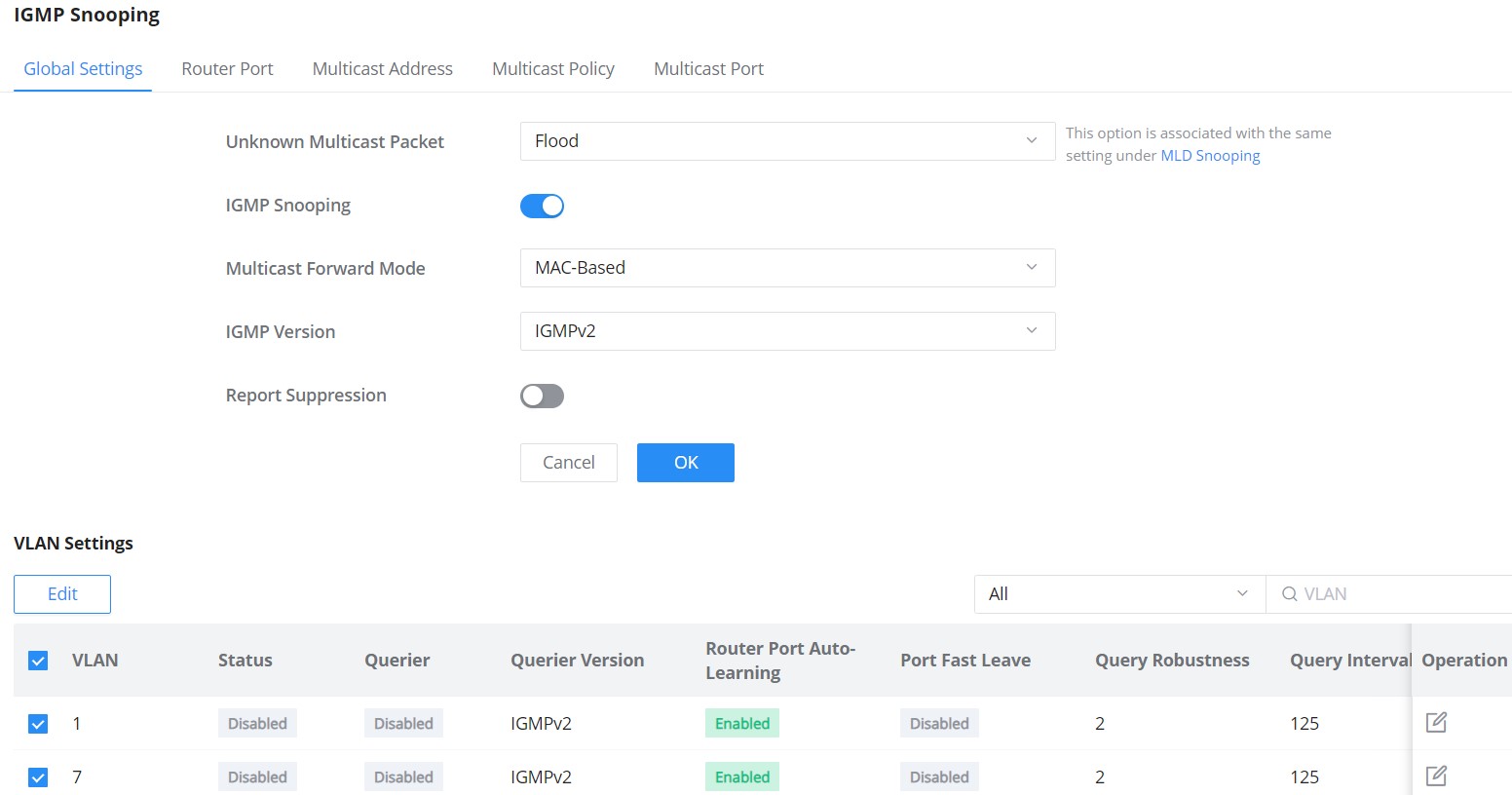
Unknown Multicast Packet | Select an action for switch to handle with unknown multicast
|
IGMP Snooping | Enable or disable GlobaI IGMP Snooping |
Multicast Forward Mode | Set the Multicast Forward Mode.
|
IGMP Version | Select the IGMP Version. |
Report Suppression | Enable or disable the switch to handle IGMP reports |
IGMP Snooping Global Settings
The user can also Enable/Disable IGMP Snooping and IGMP Snooping Querier per VLAN and much more.
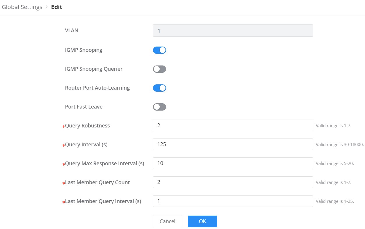
VLAN | Displays the selected VLAN |
MLD Snooping | Click on the toggle button to enable MLD Snooping for the selected VLAN. |
MLD Snooping Querier | Click the toggle button to enable the MLD Snooping Querier. |
MLD Snooping Querier Version | Select from the drop-down list the MLD Snooping Querier Version. |
Router Port Auto-Learning | Click on the toggle button to learn router port by MLD query. |
Port Fast Leave | Select Enable/Disable Fast Leave feature for the desired port. Note: If Fast Leave is enabled for a port, the switch will immediately remove this port from the multicast group upon receiving MLD leave messages. |
Query Robustness | Set a number which allows tuning for the expected packet loss on a subnet. The valid range is 1-7 |
Query Interval (s) | Set the interval of querier send general query. |
Query Max Response Interval (s) | It specifies the maximum allowed time before sending a responding report. Note: The valid range is 5-20 in seconds. |
Last Member Query Count | After quering for specified times and still not receiving any response from the subscribed member, GWN7806(P) series switches will stop transmitting data to the related GE port(s). Note: The valid range is 1-7 |
Last Member Query Interval (s) | Set The maximum time interval between counting each member query message with no responses from any subscribed member. Note: The valid range is 1-25 in seconds |
IGMP Snooping Edit VLAN
IGMP Snooping Router Port
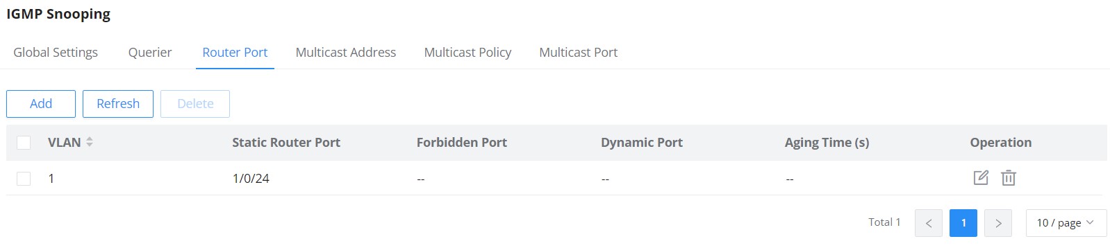
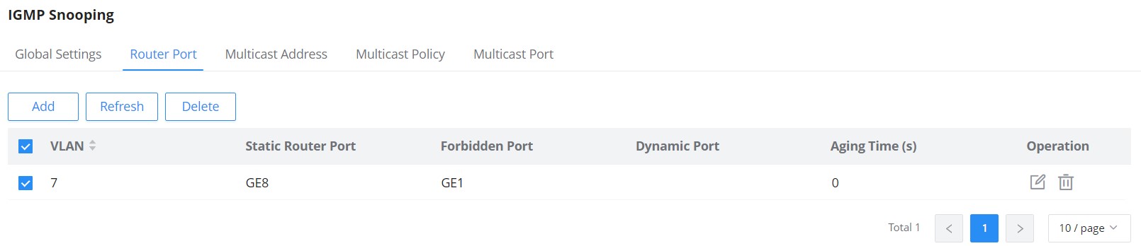
This page shows the IGMP querier router known to this switch. Click on “Add” to add another one or Click on “Edit” icon to modify already created one.
IGMP Snooping Multicast Address
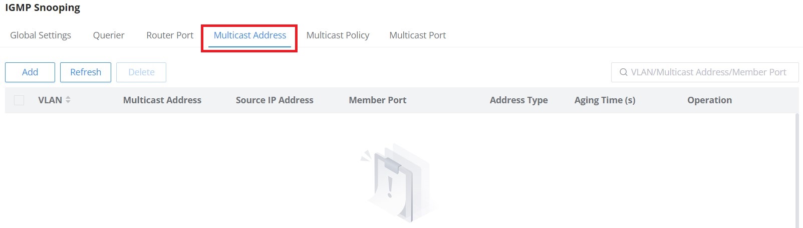
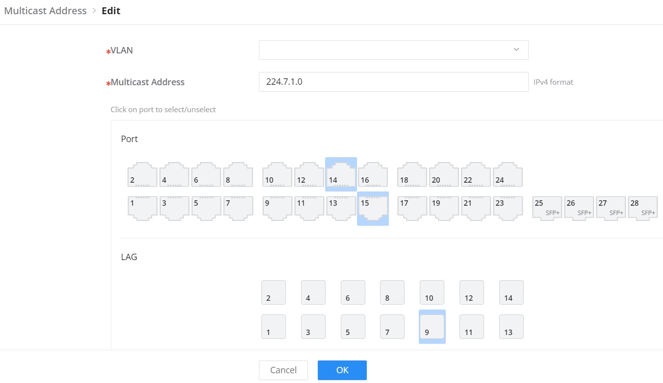
Dynamic multicast addresses will be listed here and the user can also add static multicast address entries based on VLAN by clicking on “Add” button or click “Edit”
 icon to edit.
Use the VLAN/Multicast Address/Member Port field to filter multicast-address entries by VLAN, multicast address, or member port.
Use the VLAN/Multicast Address/Member Port field to filter multicast-address entries by VLAN, multicast address, or member port.
IGMP Snooping Multicast Policy
In this page, the user can add a Multicast Policy up to 128 Policy ID to Allow or Reject a range of Multicast Addresses.
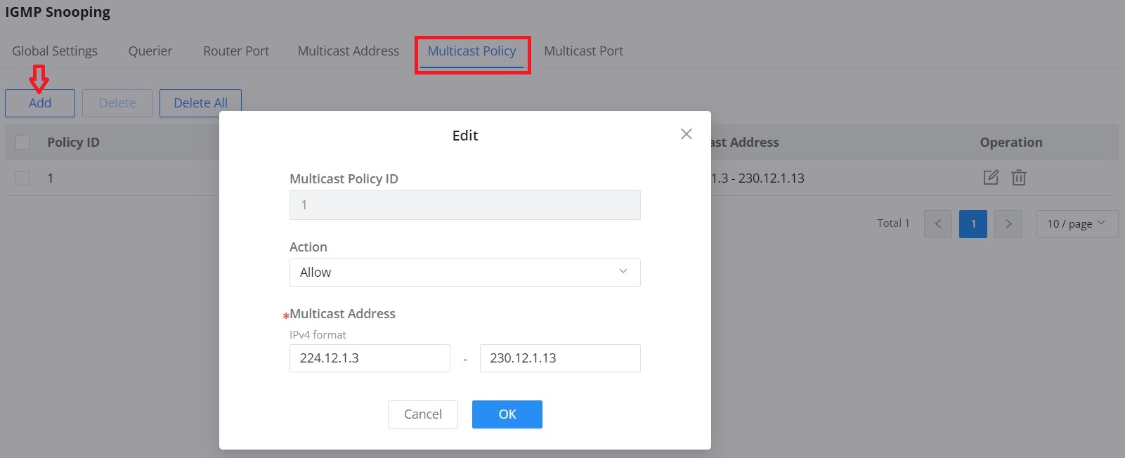
IGMP Snooping Multicast Port
Use Multicast → IGMP Snooping → Multicast Port to set the multicast group limit for a port and apply a previously created multicast policy. Click the port’s edit icon to open its settings.
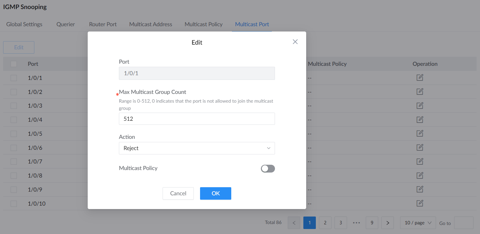
Max Multicast Group Count accepts 0–512 on GWN7806 and GWN7806P, and 0–256 on all other GWN780x models. This sets the maximum number of multicast groups the port can join; 0 prevents the port from joining multicast groups. To apply an existing policy, enable Multicast Policy and select its Multicast Policy ID.
MLD Snooping
MLD Snooping Global Settings
As an IPv6 Layer 2 multicast protocol, MLD Snooping maintains the outgoing port information of multicast packets by listening to the multicast protocol packets sent between Layer 3 multicast devices and user hosts, so as to manage and control multicast data . Forwarding of packets at the data link layer. When an MLD protocol packet transmitted between a host and an upstream Layer 3 device passes through a Layer 2 device, MLD Snooping analyzes the information carried in the packet, establishes and maintains a Layer 2 multicast forwarding table based on the information, and guides multicast data in the data stream.
Open Multicast → MLD Snooping → Global Settings to enable snooping, choose the forwarding mode and MLD version, and configure report suppression. Configure the required VLAN settings separately.
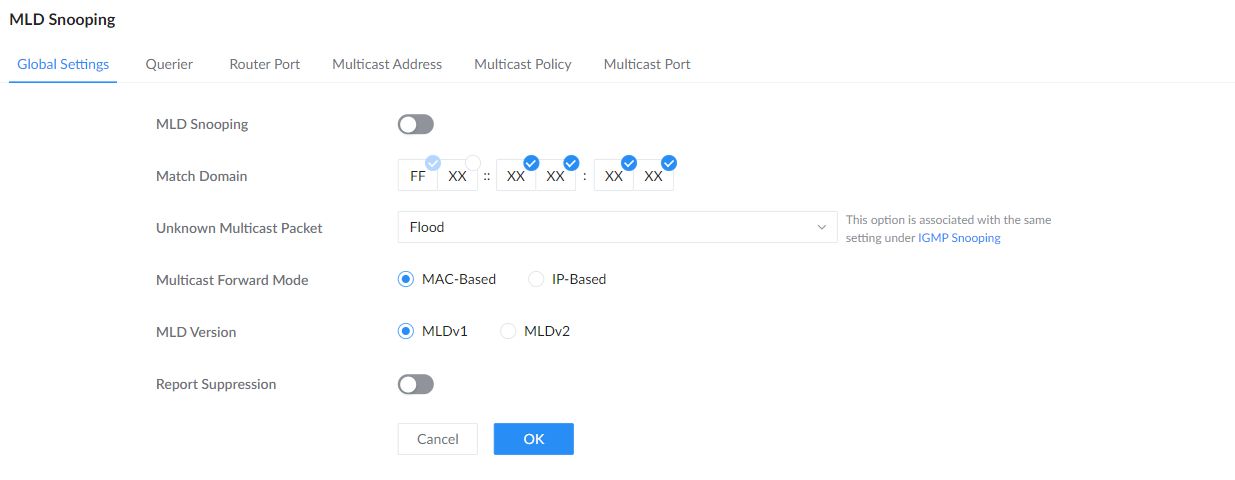
| MLD Snooping | Enable or disable MLD Snooping globally. |
|---|---|
| Match Domain | Use Match Domain to select the displayed address portions included in multicast address matching. The initial FF portion is fixed; the selectable portions are shown as XX. |
| Unknown Multicast Packet | Choose Drop, Flood, or Forward to Router port for unknown multicast traffic. This setting is shared with IGMP Snooping. |
| Multicast Forward Mode | Select MAC-Based or IP-Based forwarding. |
| MLD Version | Select MLDv1 or MLDv2. |
| Report Suppression | Suppress redundant MLD reports to reduce report traffic. |
After enabling MLD Snooping globally, open VLAN Settings to configure MLD Snooping for individual VLANs.
Click Add to create a per-VLAN MLD Snooping entry. To change an existing entry, select it and click Edit. To remove an entry, select it and click Delete.
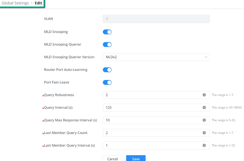
VLAN | Displays the selected VLAN |
MLD Snooping | Click on the toggle button to enable MLD Snooping for the selected VLAN. |
MLD Snooping Querier | Click the toggle button to enable the MLD Snooping Querier. |
MLD Snooping Querier Version | Select from the drop-down list the MLD Snooping Querier Version. |
Router Port Auto-Learning | Click on the toggle button to learn router port by MLD query. |
Port Fast Leave | Select Enable/Disable Fast Leave feature for the desired port. Note: If Fast Leave is enabled for a port, the switch will immediately remove this port from the multicast group upon receiving MLD leave messages. |
Query Robustness | Set a number which allows tuning for the expected packet loss on a subnet. The valid range is 1-7 |
Query Interval (s) | Set the interval of querier send general query. |
Query Max Response Interval (s) | It specifies the maximum allowed time before sending a responding report. Note: The valid range is 5-20 in seconds. |
Last Member Query Count | After quering for specified times and still not receiving any response from the subscribed member, the switch will stop transmitting data to the related GE port(s). Note: The valid range is 1-7 |
Last Member Query Interval (s) | Set The maximum time interval between counting each member query message with no responses from any subscribed member. Note: The valid range is 1-25 in seconds |
MLD Snooping – Edit VLAN
MLD Snooping Router Port
If the router port is statically configured, the Layer 2 device will also forward the MLD report and leave message to the static router port. If a static member port is configured, the interface will be added as the outgoing interface in the forwarding table. After a Layer 2 multicast forwarding table entry is established on a Layer 2 device, when the Layer 2 device receives a multicast data packet, it searches for the forwarding table according to the VLAN to which the packet belongs and the destination address of the packet (that is, the IPv6 multicast group address). Whether the item has the corresponding “outbound interface information”. If it exists, the packet is sent to all multicast group member ports; if it does not exist, the packet is discarded or broadcast in the VLAN.
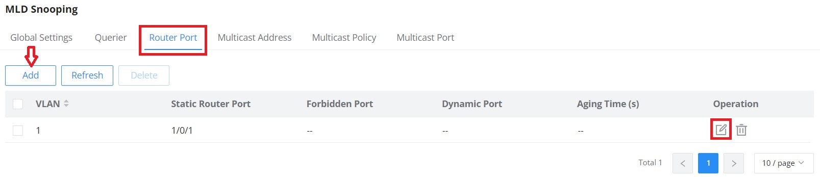
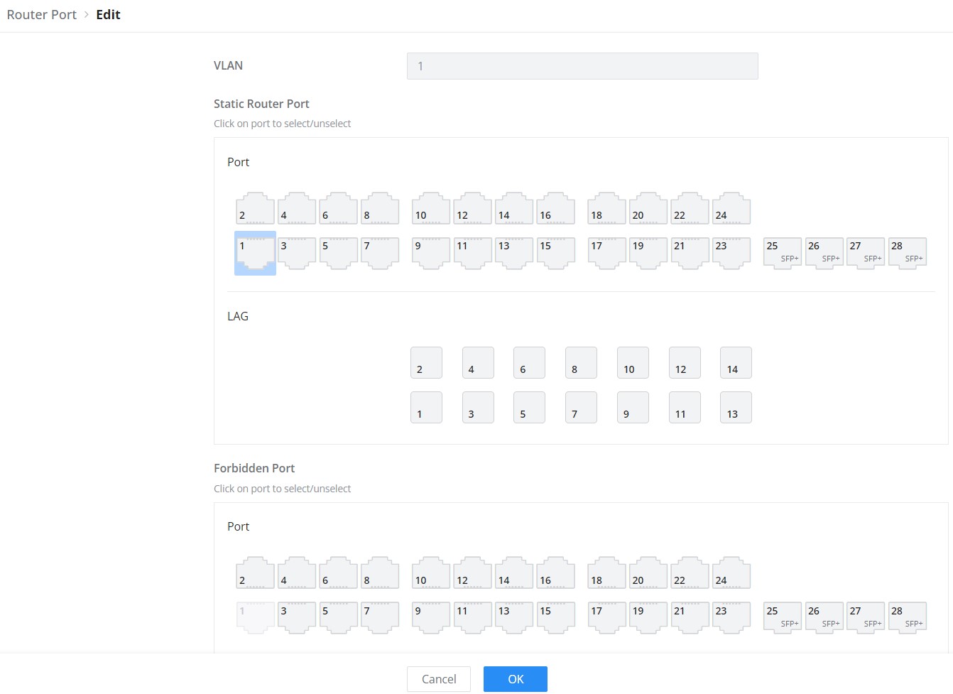
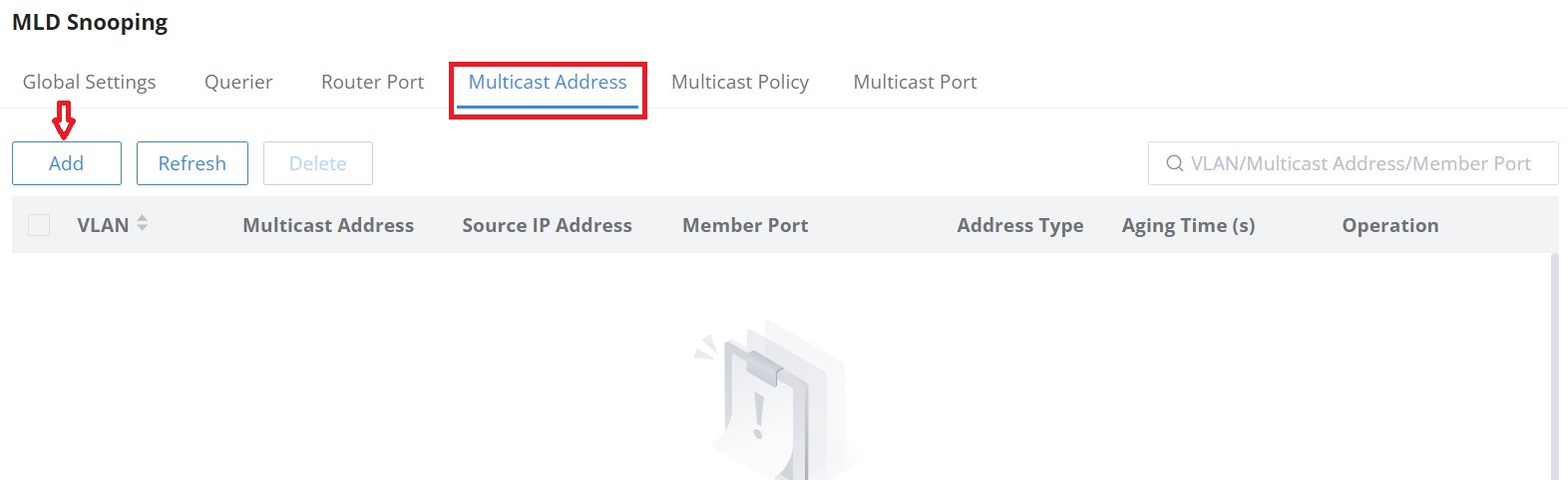
MLD Snooping Multicast Address
GWN780x Switches do also support adding static multicast addresses by specifying the VLAN and member port.
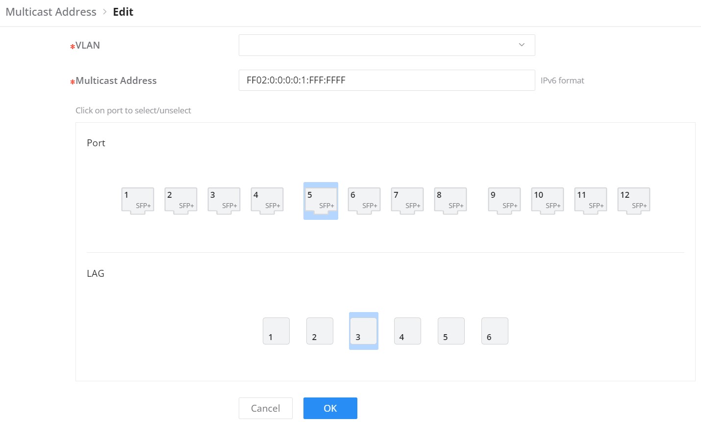
MLD Snooping Multicast Policy
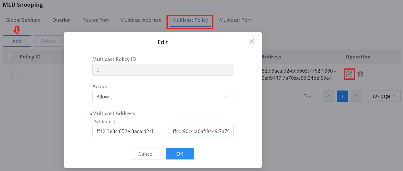
Multicast Policy can be created in this page to allow or reject a range of IPv6 Multicast Addresses. Up to 128 Policy can be created.
MLD Snooping Multicast Port
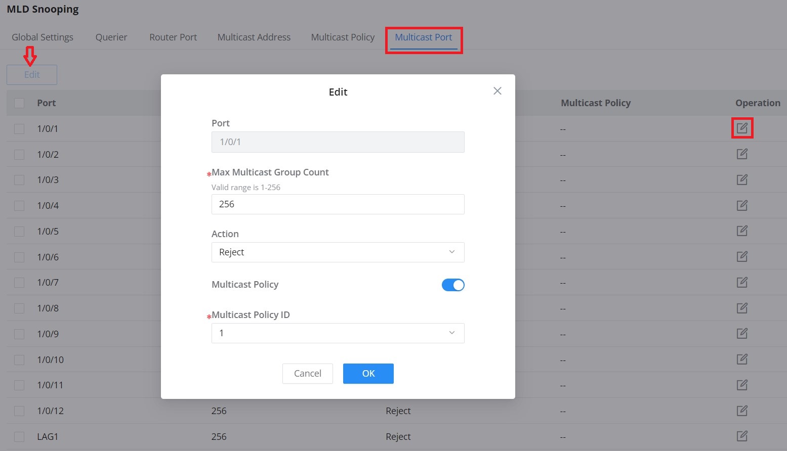
The multicast policy can be applied to the Gigabit Ethernet/LAG port, the user can also set the maximum number of multicast groups that the port is allowed to join and set the action when the port multicast exceeds the limit, the default is rejected.
ROUTING
Routing is a process in which the router selects the optimal path according to the destination address of the received data packet and forwards it to the next network node leading to the target network, and the last routing node under this path forwards the data to the target host. (Router refers to both a router in the traditional sense and an Ethernet switch running a routing protocol).
GWN780x support IPv4 and IPv6 static routing.
Routing Table
A routing table is like a map of the network that shows the best routes to each destination. It achieves this by storing information on how to reach different destinations on a network and with this table the router can decide where to forward packets that it receives from other devices.
To get to the Routing Table, please navigate to Web UI → Routing → Routing Table.
You cane enable/disable Routing Forwarding option, which allows the switch to act as a Layer 3 device, enabling it to forward packets between different networks or VLANs based on the routing table entries.
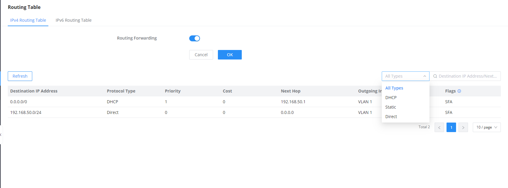
A routing table contains the following information for each entry: Destination IP address, Mask Length, Protocol Type, Priority, Next Hop, outgoing Interface and Flags.
A routing table gets populated over time with dynamic routing protocols like OSPF and RIP or static entries (manually configured by an administrator) or directly connected networks.
Static Routes
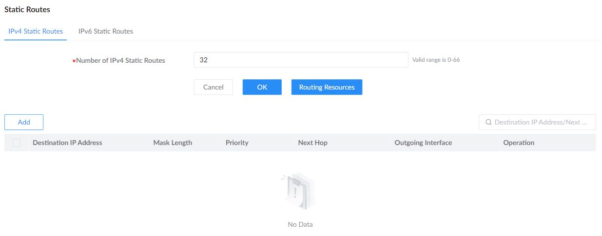
Static routes specify how the switch reaches a destination network. Configure the destination and a next-hop address or outgoing interface under Web UI → Routing → Static Routes. Use the IPv4 Static Routes and IPv6 Static Routes tabs for the corresponding address family.
Static Route Capacity
The Number of IPv4 Static Routes or Number of IPv6 Static Routes field sets the maximum number of static routes for that address family. This reserves route capacity; it does not create route entries. To change the capacity, enter a value within the range shown by the switch and click OK. Use the current device’s displayed limit, since capacity differs by model and available routing resources.
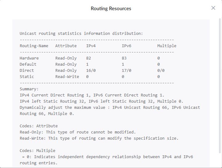
Click Routing Resources to view the routing-resource breakdown, remaining static-route capacity, and the current maximum that can be allocated. The dialog identifies route types whose capacity is Read-Only and those marked Read-Write, whose capacity can be adjusted.
Add a Static Route
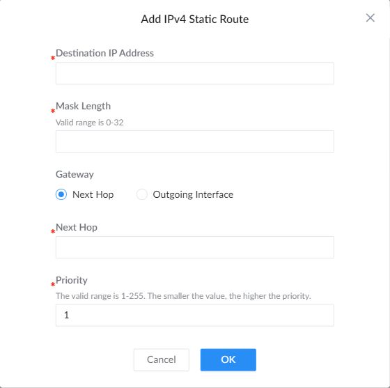
On the IPv4 Static Routes tab, click Add. Enter the Destination IP Address and Mask Length. Under Gateway, choose Next Hop to enter the next-hop address, or Outgoing Interface to select the interface. Set the route priority, then click OK to add the entry. A smaller priority value has higher priority.
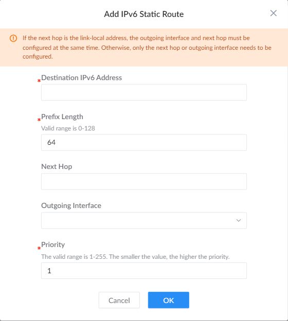
For IPv6, select IPv6 Static Routes and click Add. Enter the Destination IPv6 Address and Prefix Length, then specify the next hop or outgoing interface. If the next hop is a link-local address, configure both the next hop and outgoing interface. Set the priority and click OK.
Policy Route
Policy routes forward traffic matching a selected ACL rule to a specified next hop. Open Routing → Policy Route and choose the IPv4 or IPv6 tab for the traffic you want to match. Configure the ACL first, then click Add to create the policy.
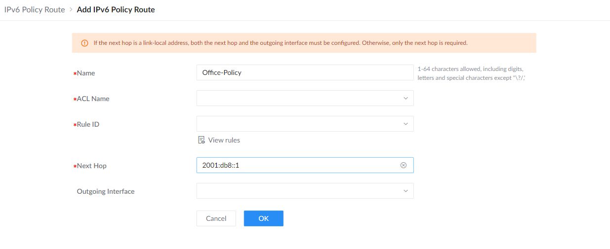
| Name | Enter a descriptive policy name. |
|---|---|
| ACL Name / Rule ID | Select the ACL and rule that identify the traffic. Use View rules to check the selected rule. |
| Next Hop | Enter the next-hop address for the selected address family. |
| Outgoing Interface | For an IPv6 link-local next hop, also select the outgoing interface. For other IPv6 next hops, only the next-hop address is required. |
Click OK when the policy is ready, then save the pending configuration. The illustrated form shows example values, not an applied policy.
POE
Power Over Ethernet (PoE) refers to supplying power over an Ethernet network, also known as a local area network-based power supply system PoL or Active Ethernet.
Usually, the terminal devices of the access point need to use a DC power supply, but due to insufficient wiring, these devices need unified power management. At this time, the switch interface provides the power supply function, which can solve the above problems and realize the precise control of the port PoE power supply.
Global
This page Displays the Power Supply Info like the number of PoE, Total and Remaining PoE Power, etc, and even the Supply Voltage.
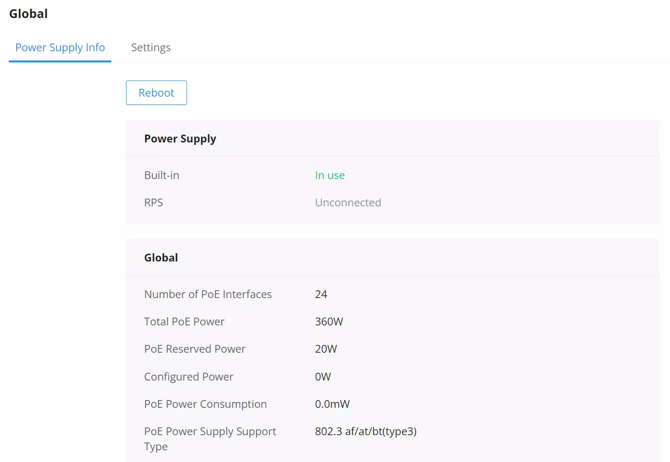
Click on button to soft restart the PoE module function.
PoE Reserved Power
PoE Reserved Power (W) specifies the power held in reserve by the PoE power supply. The default is 20 W.
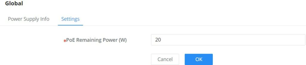
Application scenarios:
The device will dynamically allocate power to each interface according to the power consumed by each interface. During the running process of each PD device, its power consumption will continue to change, and the system will periodically calculate the total power required by all currently connected PDs. Whether the upper limit of the available PoE power is exceeded, if it exceeds, the system will automatically power off the PD device on the interface with lower priority to ensure the normal operation of other devices. However, sometimes there will be a sudden surge in power consumption, the remaining available power of the system cannot support this surge in demand, and the system has not yet had time to calculate the total power consumption exceeding the limit, to disconnect the power supply of the interface with lower priority. When the PoE power supply is overloaded, the overload protection will be powered off, and all PD devices will be powered off. Use the PoE power-reserved command to reasonably set the reserved power of the system. In the event of a sudden surge in power demand, the reserved power of the system can support the sudden demand and ensure that the system has time to power off the devices on the interfaces with low priority. method to ensure the stable operation of other equipment.
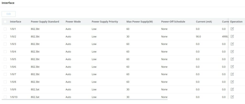
Interface PoE configuration
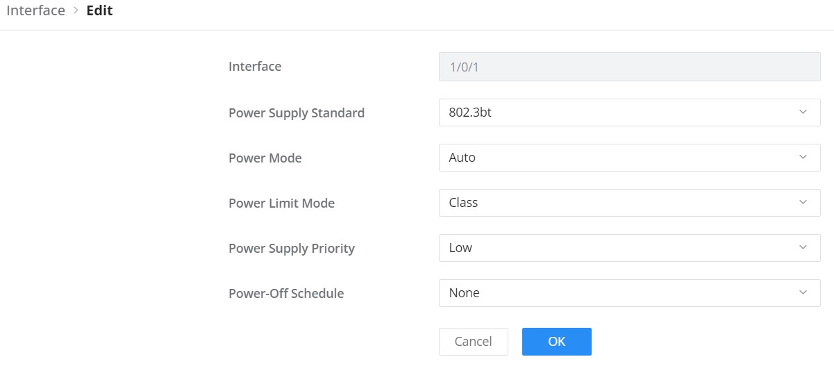
Select the switch interface that supports the PoE power supply to be configured. Multiple choices are possible.
Click on the “Edit” button or icon to change the configuration per port including Power Supply Standard, Power Mode, Power Limit Mode, and Power Supply Priority.
QOS
The popularity of the network and the diversification of services have led to a surge in Internet traffic, resulting in network congestion, increased forwarding delay, and even packet loss in severe cases, resulting in reduced service quality or even unavailability. Therefore, to carry out these real-time services on the network, it is necessary to solve the problem of network congestion. The best way is to increase the bandwidth of the network, but considering the cost of operation and maintenance, this is not realistic. The most effective solution is to apply a ” Guaranteed ” policies govern network traffic. QoS technology is developed under this background. QoS is quality of service, and its purpose is to provide end-to-end service quality assurance for various business needs. QoS is a tool for effectively utilizing network resources. It allows different traffic flows to compete for network resources unequally. Voice, video, and important data applications can be prioritized in network equipment.
Port Priority
On this page, the user can enable/disable port priority for each interface (port/LAG), supported modes are (CoS, DSCP, CoS-DSCP, or IP-Precedence).
Please navigate to Web UI → QoS → Port Priority page.
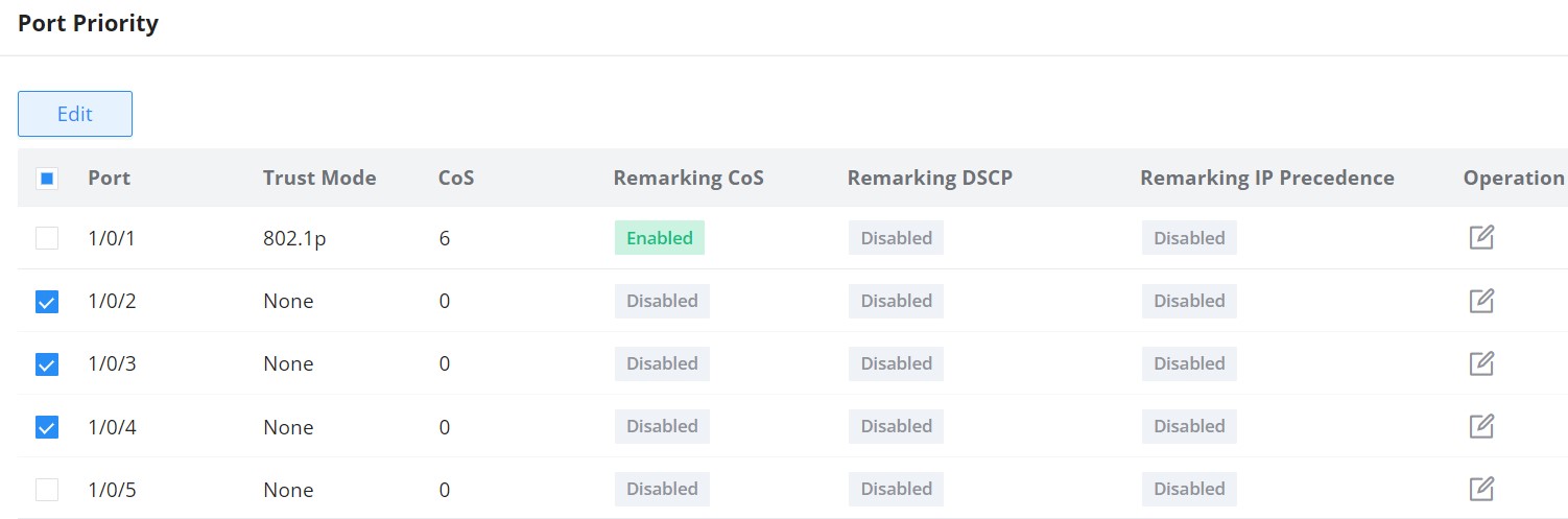
Then the user can click on the “Edit” button for further configuration per Port/LAG.
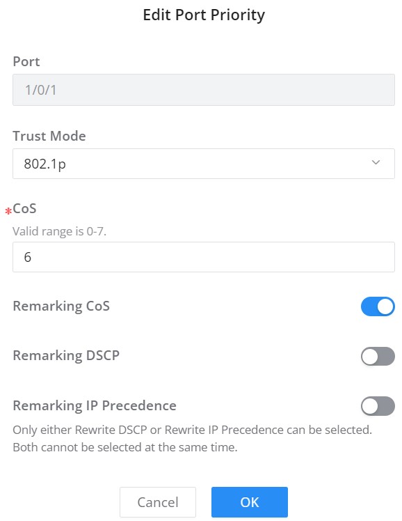
Port | Displays the selected port GE/LAG. |
Trust Mode | Select the QoS operation mode:
|
CoS | Set the CoS value of the interface, the value range is an integer from 0 to 7 (7 is the highest priority ), the default is 0. |
Remarking CoS | Set whether to enable Remarking CoS function of outgoing packets, which is disabled by default. |
Remarking DSCP | Set whether to enable Remarking DSCP function of outgoing packets, and it is disabled by default. |
Re-marking IP Precedence | Set whether to enable Remarking IP Precedence function of outgoing packets, and it is disabled by default. Note : Only one of DSCP and IP Precedence re-marking can be enabled. |
QoS Port Priority
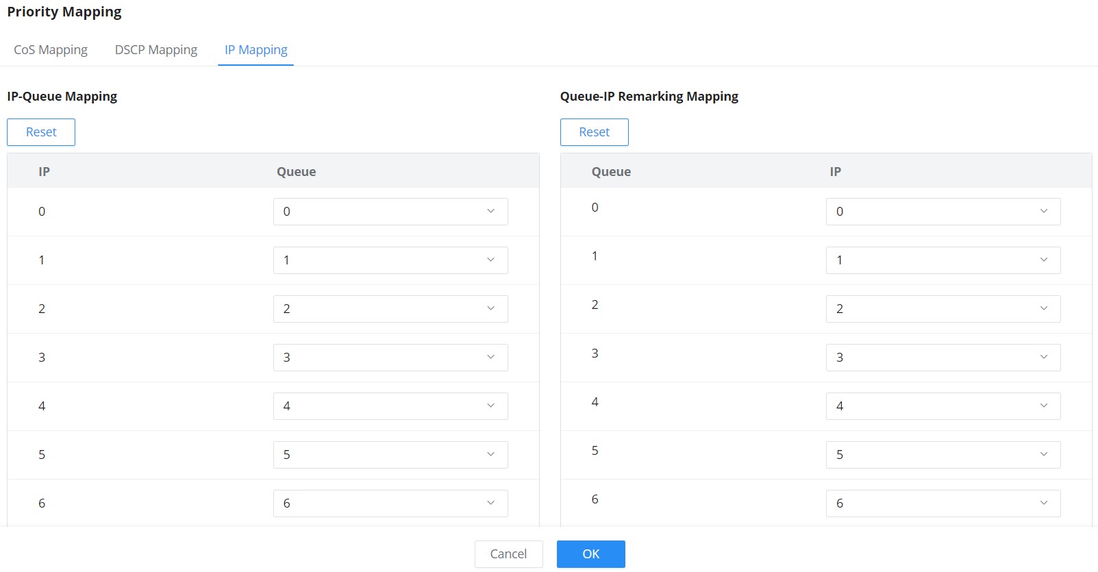
Priority Mapping
Priority mapping is used to realize the conversion between the QoS priority carried in the packet and the internal priority of the device ( also known as the local priority, which is the priority used by the device to differentiate the service level of the packet ) so that the device provides the Differentiated QoS service quality. Users can use different QoS priority fields in different networks according to network planning.
- CoS Mapping
Shows the mapping relationship between queues and CoS remarking priorities.
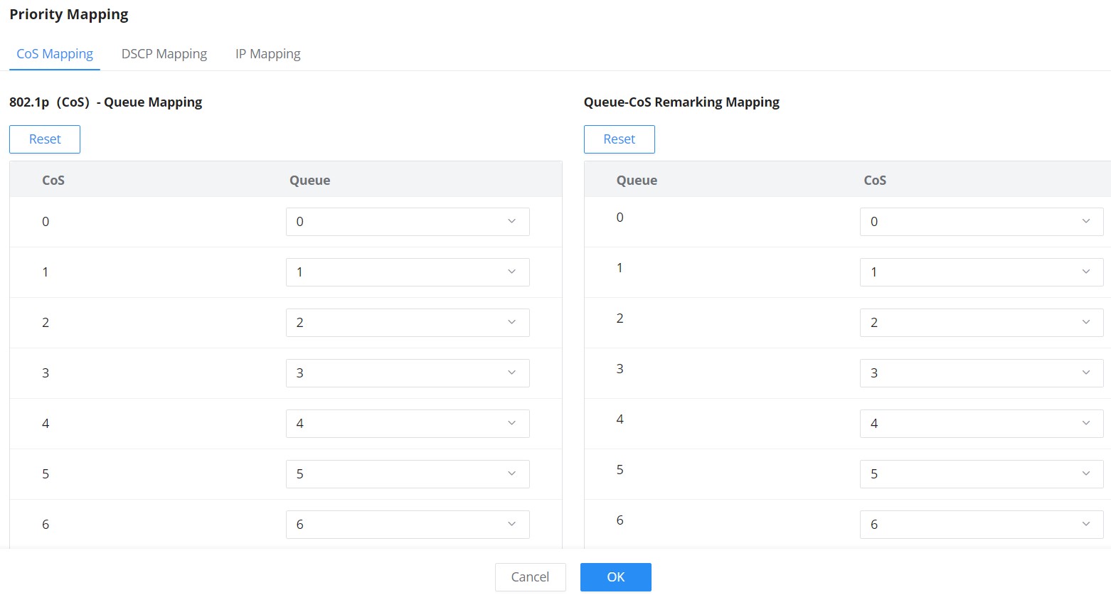
- DSCP Mapping
Shows the mapping relationship between DSCP values and queue priorities.
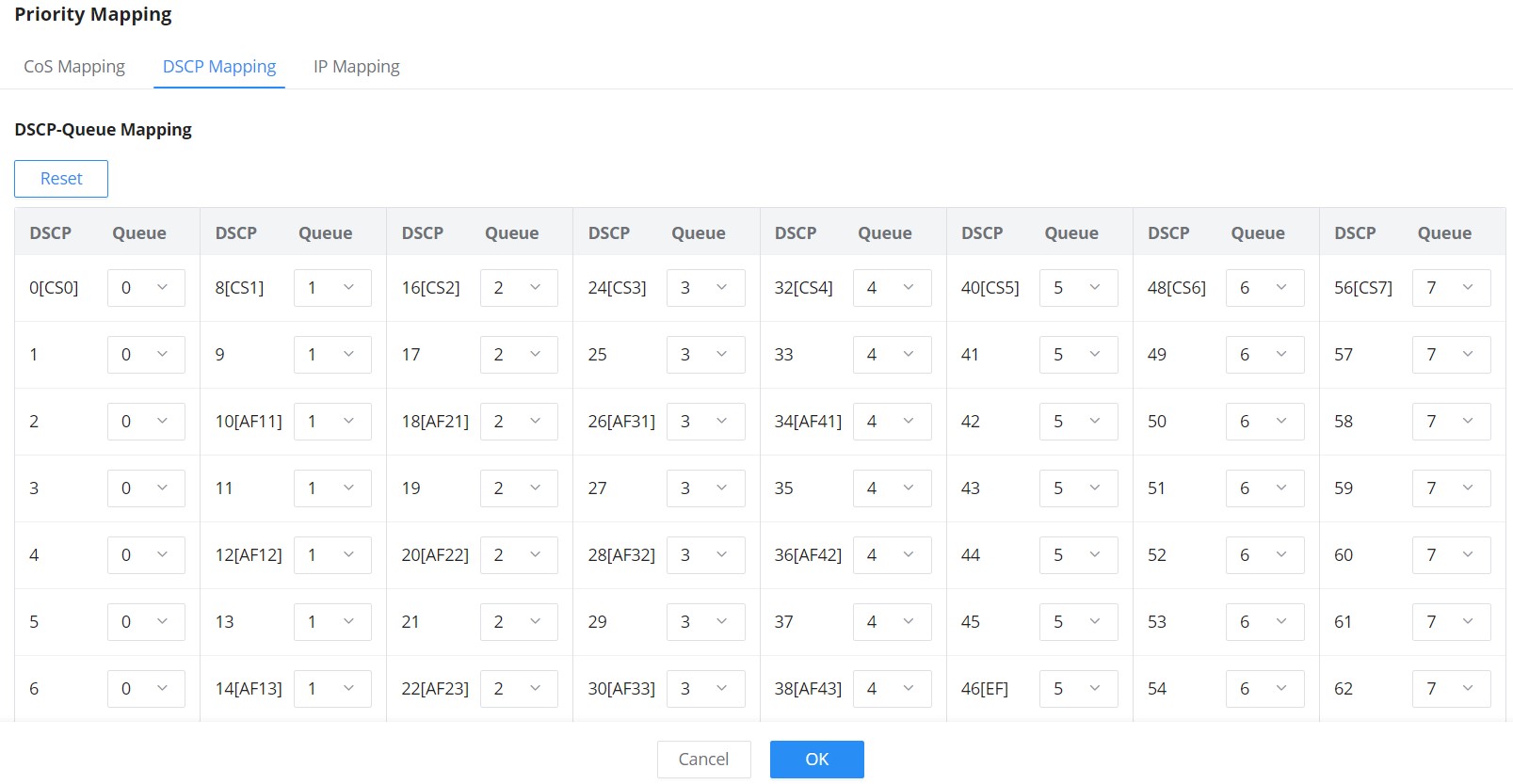
- IP Mapping
Shows the mapping relationship between IP priority and queue.
Queue Scheduling
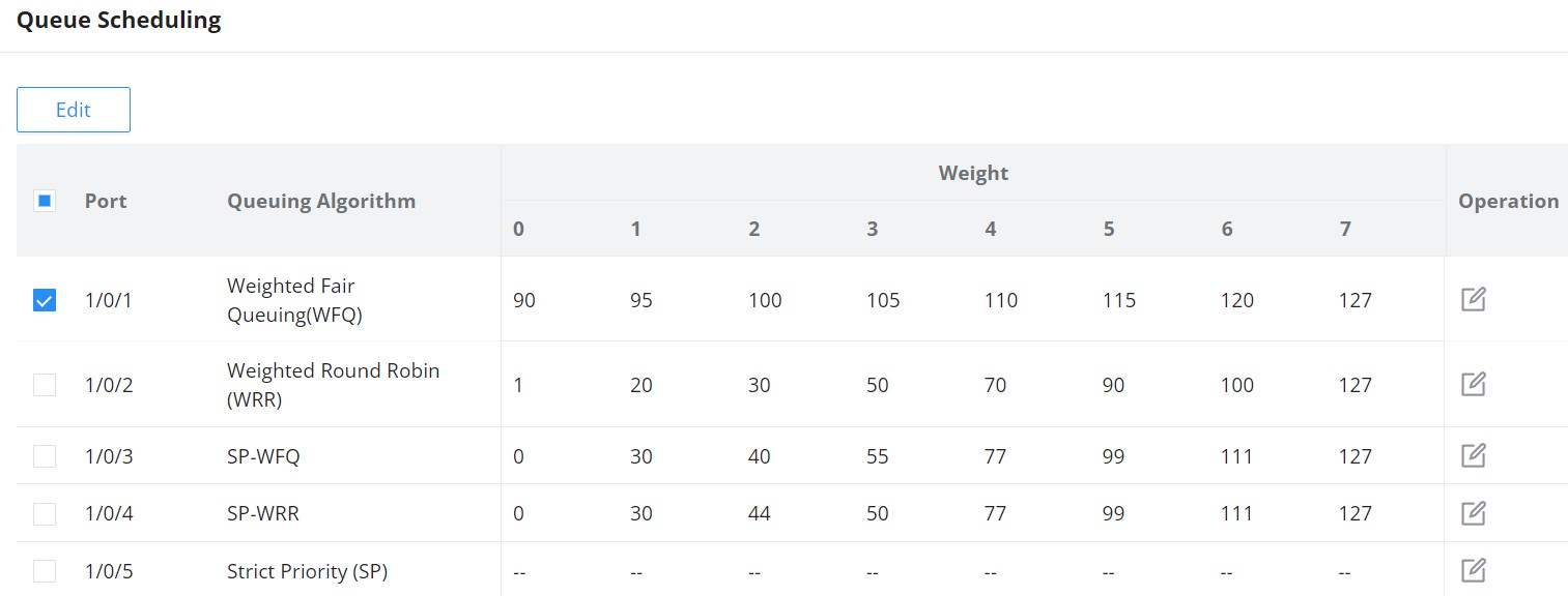
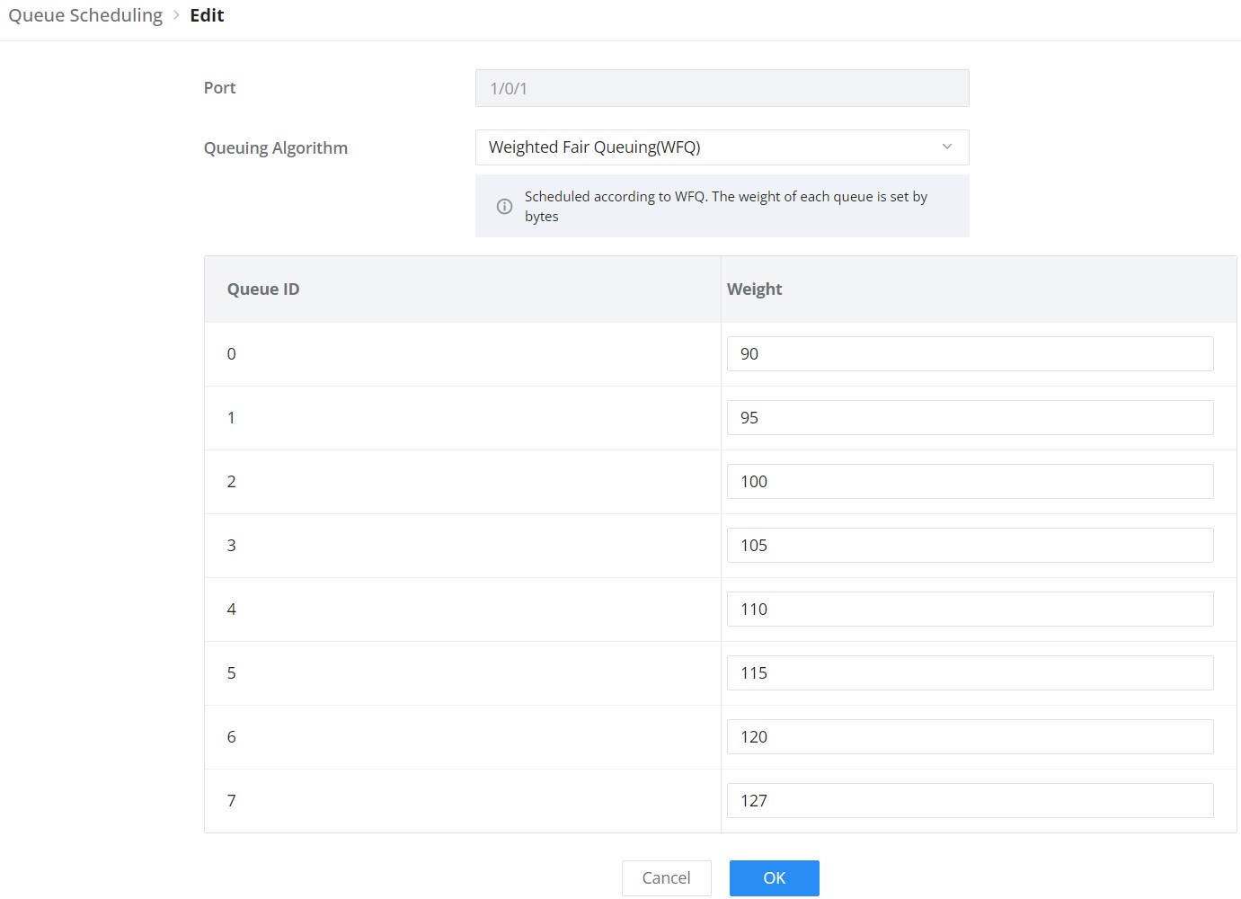
When congestion occurs in the network, the device will determine the processing order of forwarding packets according to the specified scheduling policy, so that high-priority packets are preferentially scheduled.
Queue scheduling algorithm: queue scheduling according to the switch interface.
- Strict priority (SP, Strict Priority) scheduling: The flow with the highest priority is served first, and the flow with the second highest priority is served until there is no flow at that priority. Each interface of the switch supports 8 queues ( queues 0-7 ), queue 7 is the highest priority queue, and queue 0 is the lowest priority queue. Disadvantage: When congestion occurs, if there are packets in the high-priority queue for a long time, the packets in the low-priority queue cannot be scheduled, and data cannot be transmitted.
- Weighted Round Robin (WRR, Weighted Round Robin) scheduling: each priority queue is allocated a certain bandwidth, and provides services for each priority queue according to the priority from high to low. When the high-priority queue has used up all the allocated bandwidth, it is automatically switched to the next priority queue to serve it.
- Weighted Fair Queuing (WFQ): Based on ensuring fairness ( bandwidth, delay) as much as possible, priority considerations are added, so that high-priority packets have more opportunities for priority scheduling than low-priority packets. WFQ can automatically classify flows by their “session” information (protocol type, source and destination IP addresses, source, and destination TCP or UDP ports, priority bits in the ToS field, etc.) Place each flow evenly into different queues, thus balancing the latency of the individual flows as a whole. When dequeuing, WFQ allocates the bandwidth that each flow should occupy at the egress according to the flow priority (Precedence) . The smaller the priority value is, the less bandwidth is obtained; otherwise, the more bandwidth is obtained.
- SP-WRR: the switch schedules packets in the SP scheduling group preferentially, and when the SP scheduling group is empty, schedules the packets in the WRR scheduling group. Queues in the SP scheduling group are scheduled with the SP queue scheduling algorithm. Queues in the WRR scheduling group are scheduled with WRR.
- SP-WFQ: the switch schedules packets of queues in the WFQ group based on their minimum guaranteed bandwidth settings, then uses SP queuing to schedule the queues in the SP scheduling group, then uses WFQ to schedule the queues in the WFQ scheduling group in a round robin fashion according to their weights.
Queue Shaping
When the packet sending rate is higher than the receiving rate, or the interface rate of the downstream device is lower than the interface rate of the upstream device, network congestion may occur. If the size of the service traffic sent by users is not limited, the continuous burst of service data from a large number of users will make the network more congested. To make the limited network resources serve users more effectively, it is necessary to restrict the service flow of users.
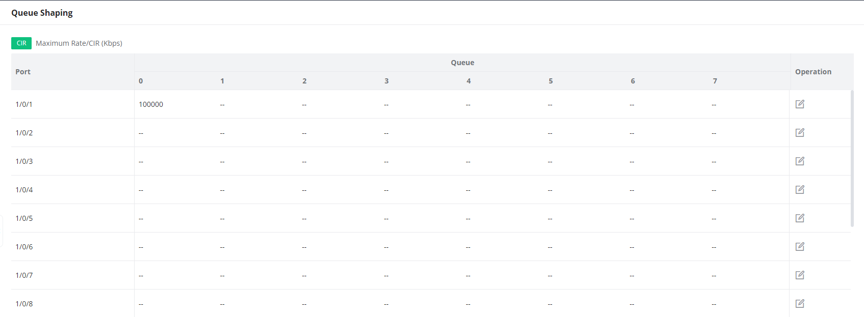
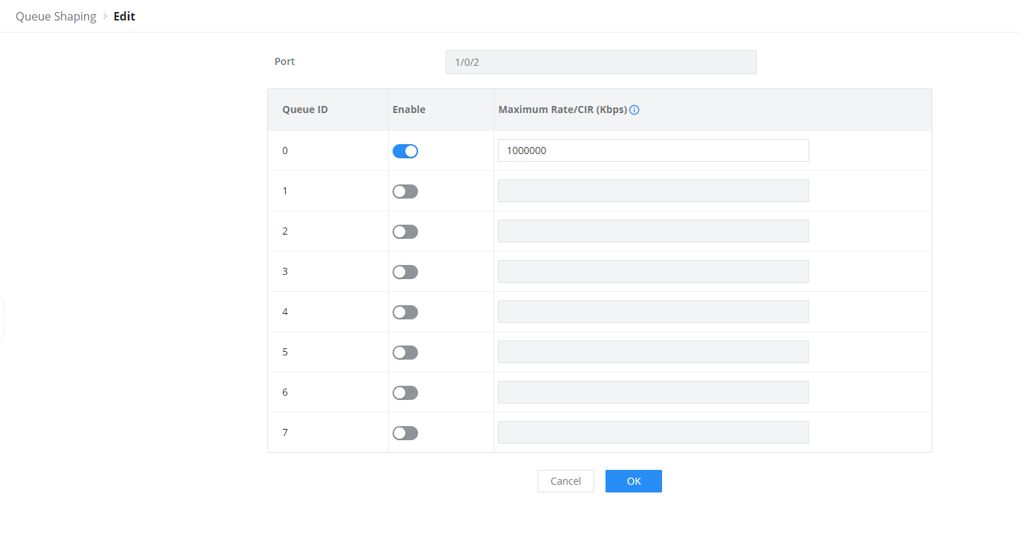
To configure a port, click on the “Edit” icon under the operation column.
Maximum Rate/CIR (Kbps): Configures the maximum rate of shaping. The value must be an integer between 16-1000000 Kbps and must be multiples of 16. By default, it’s the port rate.
Rate Limit
Interface rate limit can limit the total rate of all packets sent or received on an interface. The interface rate limit also uses the token bucket to control the flow. If an interface rate limit is configured on an interface of the device, all packets sent through this interface must first be processed through the token bucket of the interface rate limiter. If there are enough tokens in the token bucket, the packet can be sent; otherwise, the packet will be discarded or cached.
To configure Rate Limit, please navigate to Web UI → QoS → Rate Limit.

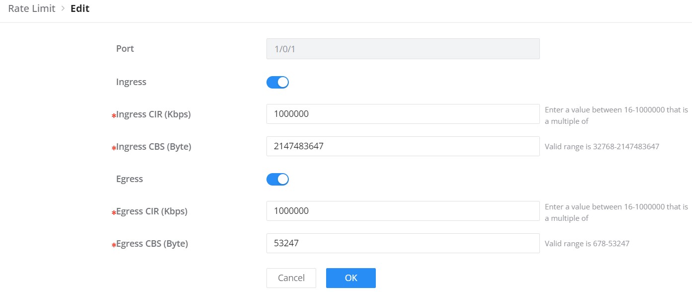
To configure a port, click on the “Edit” icon under operation column, then set the CIR and CBS for both Ingress and Egress.
CIR (Committed Information Rate): the guaranteed average transmission rate or the minimum guaranteed traffic delivered in the network.
CBS (Committed Burst Size): the average volume of burst traffic that can pass through an interface.
In Rate Limit Settings, Burst Packet (pps) sets the permitted packet burst and Burst Byte (Bps) sets the permitted byte burst for the corresponding rate-limit mode.
In Rate Limit Settings, Burst Packet (pps) sets the permitted packet burst and Burst Byte (Bps) sets the permitted byte burst for the corresponding rate-limit mode.
SECURITY
GWN780x Switches series support many tools and features to enhance the security of the device against misconfiguration or attacks.
Storm Control
Traffic suppression can limit the rate of broadcast, unknown multicast , unknown unicast, known multicast, and known unicast packets by configuring thresholds , preventing broadcast, unknown multicast packets, and unknown unicast packets from generating broadcast storms. Large traffic impact of known multicast packets and known unicast packets.
Storm control can block the traffic of broadcast, unknown multicast and unknown unicast packets by blocking packets or shutting down ports . The device supports storm control for the above three types of packets on the interface according to the packet rate, byte rate, and percentage . During a detection interval, the device monitors the average rate of three types of packets received on the interface and compares it with the configured maximum threshold. When the packet rate is greater than the configured maximum threshold , the device performs storm control on the interface and executes the Configured storm control actions. Storm control actions include blocking packets and shutting down / shutdown interfaces.
- If packets are blocked, when the average rate of receiving packets on the interface is less than the specified minimum threshold, storm control will release the blocking of the packets on the interface.
- If the action is to shut down / shutdown the interface, you need to manually run the command to bring up the interface, or enable the interface state to automatically return to UP, it’s also possible to use the Auto Recovery function to bring up the interface automatically.
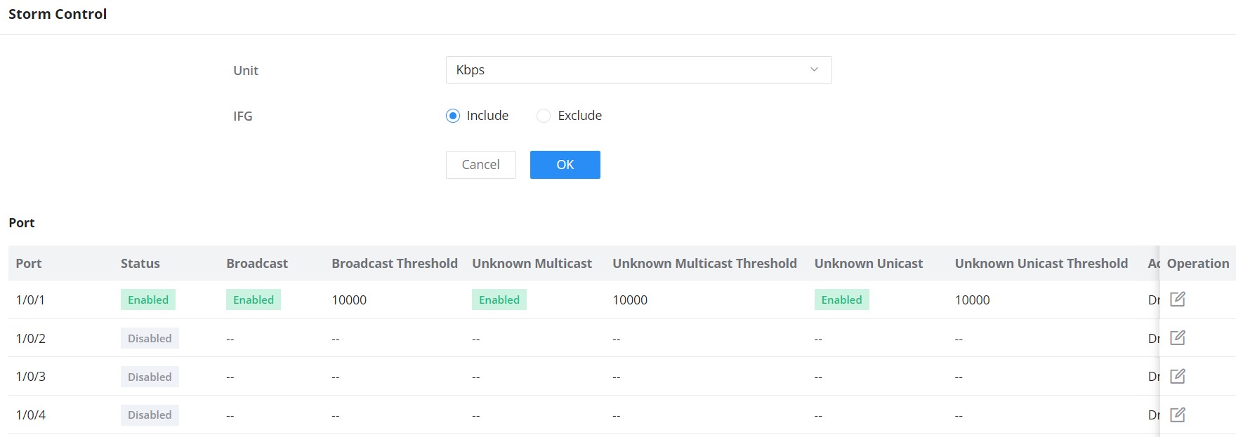
Unit | Select Unit:
|
IFG | Select IFG ( Inter Frame Gap ):
|
Storm Control → Edit | |
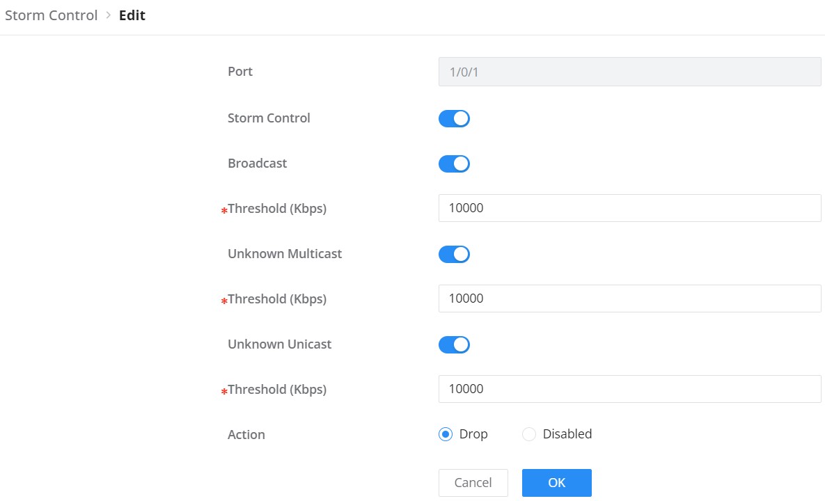
Port | Displays the selected port. |
Storm Control | Select whether to enable Storm Control on the selected port or not. |
Broadcast | Set whether to enable the storm threshold setting for broadcast packets. If Enabled Please enter a Treshhold (Kbps). Note: The valid range is 16~1000000, which must be a multiple of 16. Default is 10000. |
Unknown Multicast | Set whether to enable the storm threshold setting for the Unknown Multicast packets If Enabled Please enter a Treshhold (Kbps). Note: The valid range is 16~1000000, which must be a multiple of 16. Default is 10000. |
Unknown Unicast | Set whether to enable the storm threshold setting for the Unknown Unicast packets. If Enabled Please enter a Treshhold (Kbps). Note: The valid range is 16~1000000, which must be a multiple of 16. Default is 10000. |
Action | Select the state of setting
|
Storm Control
Port Security
By converting the MAC address learned by the interface into secure MAC addresses ( including secure dynamic MAC address, secure static MAC address and Sticky MAC) , port security prevents illegal users from communicating with the switch through this interface, thereby enhancing the security of the device.
Security MAC addresses are divided into: Secure Dynamic MAC, Secure Static MAC and Sticky MAC.
Secure Dynamic MAC Address | If enabled but the Sticky MAC function is not enabled. | If the device is restarted, the entries will be lost and need to be relearned. |
Secure Static MAC Address | Static MAC address manually configured when port security is enabled. | The entries will not be aged, and will not be lost after a reboot. |
Sticky MAC Address | The MAC address converted after the port security is enabled and the Sticky MAC function is enabled at the same time | The entries will not be aged , and the addresses will not be lost after restarting the device. |
Secure MAC Address Types
Open Security → Port Security and enable the feature globally with Allow. Edit the required port to configure secure-address learning, its allowed MAC-address limit, Sticky MAC, and the protective action. The Secure MAC Addresses tab provides the corresponding address view.
On GWN7801(P), GWN7802(P), and GWN7803(P), the global page also includes Rate Limit (packet/s). Configure this field separately from the per-port MAC-address limit. The available limits depend on the model; use the values shown in its Web UI.
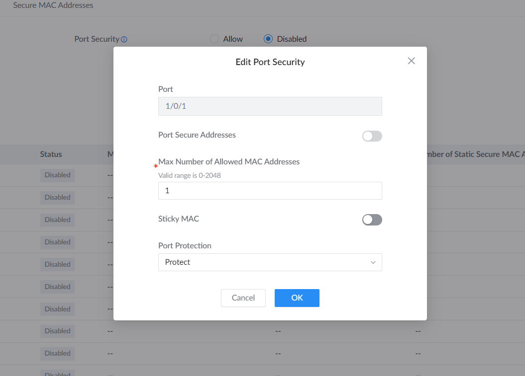
| Port Secure Addresses | Enable secure-address control on the selected port. This control depends on global Port Security being enabled. |
|---|---|
| Max Number of Allowed MAC Addresses | Set the permitted address limit for the interface. The valid range is 0–256 for all GWN780x models except GWN7806(P), which supports 0–2048. When an unknown source exceeds the limit, the selected protection action applies. |
| Sticky MAC | Convert learned secure dynamic addresses to Sticky MAC entries when enabled. |
| Port Protection | Protect drops traffic from unknown source MAC addresses without reporting an alarm. Restrict drops that traffic and reports an alarm. Shut Down puts the interface into an error-disabled state and reports an alarm. |
| Recovery after Shut Down | Restore the affected interface deliberately, or configure the appropriate Port Auto Recovery behavior when automatic recovery is required. |
On Secure MAC Addresses, use the VLAN/MAC Address/Port field to filter entries.
On Secure MAC Addresses, use the VLAN/MAC Address/Port field to filter entries.
Port Isolation
Port isolation prevents selected switch ports from sending traffic to one another without placing them in separate VLANs. Open Security → Port Isolation. On GWN7806 and GWN7806P, Isolation Mode also determines whether routed communication between those ports remains allowed; the choices are explained below.
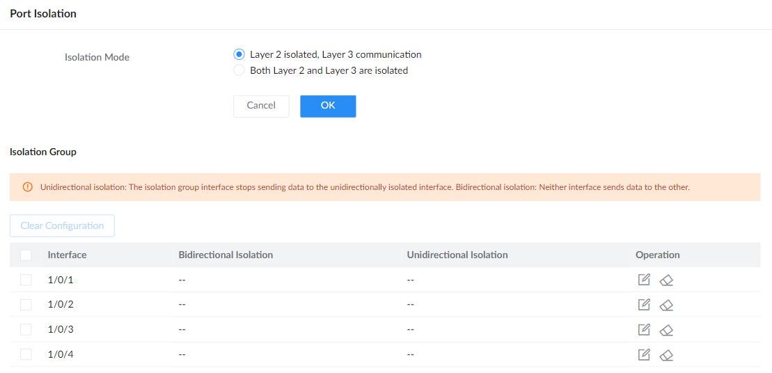
Find the interface you want to isolate and click its Edit icon. In Edit Isolation Group, select the other ports or LAGs (groups of linked ports) whose communication with that interface should be restricted. Use Bidirectional Isolation to block communication in both directions, or Unidirectional Isolation to stop the edited interface from sending to the selected interfaces without imposing the reverse restriction. Click a port again to remove its selection. Click OK to apply the choices, or Cancel to leave them unchanged.
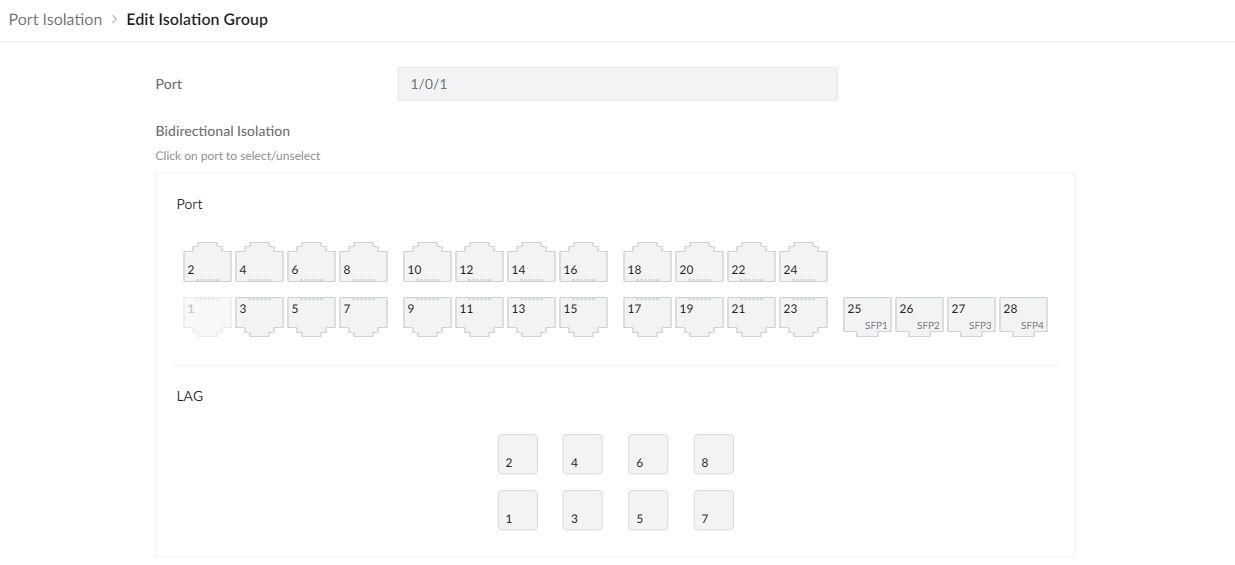
The Unidirectional Isolation selection area appears below the bidirectional area in the same editor. For example, editing port 1 and selecting port 2 there blocks traffic from port 1 to port 2; it does not add the reverse restriction. Selecting port 2 under Bidirectional Isolation blocks both directions.
| Isolation Mode | On GWN7806 and GWN7806P, choose which types of communication to block between the interfaces selected for isolation:
The interface selections under Bidirectional Isolation and Unidirectional Isolation determine which interfaces are isolated and in which direction. |
|---|---|
| Bidirectional Isolation | Neither the edited interface nor the selected peer interface sends data to the other. |
| Unidirectional Isolation | The edited isolation-group interface stops sending data to the selected peer interface. This selection does not impose the reverse restriction. |
| Port / LAG selection | Select or unselect the peer interfaces in the corresponding directional group. |
ACL
Access control list (ACL) is a collection of one or more rules. A rule is a judgment statement that describes the matching conditions of a packet. These conditions can be the source address, destination address, port number, etc. of the packet. ACL is essentially a packet filter, and the rule is the filter element of the filter. The device matches packets based on these rules, filters out specific packets , and allows or organizes the packets to pass through according to the processing policy of the service module that applies the ACL.
IPv4/IPv6 ACL
To add an IPv4 or IPv6 ACL rule, navigate to Security → ACL → IPv4 tab or IPv6 tab, then click on “Add” button to add an IPv4/IPv6 based ACL rule.

The rules action can be defined in one of the four ways below:
- Drop: This action denies or blocks traffic that matches the specified ACL rule, which prevents the packet from being forwarded through the network.
- Allow: This action permits traffic that matches the ACL rule, allowing the packet to pass through and continue to its destination.
- Shut Down: This action disables the interface or port that the traffic is passing through if the ACL rule is triggered, effectively stopping all traffic on that interface.
- Redirect to Interface: This action forwards the traffic matching the ACL rule to a different interface than it was originally destined for, often used for traffic monitoring, load balancing, or security purposes.

Enable Statistics under the ACL rule’s Advanced Settings to count matching traffic. In the illustrated rule list, the information icon under Operation opens Statistics Details, which shows the rule ID, packet count, and Statistics Rate in packets per second (pps). Use Refresh to retrieve current values.
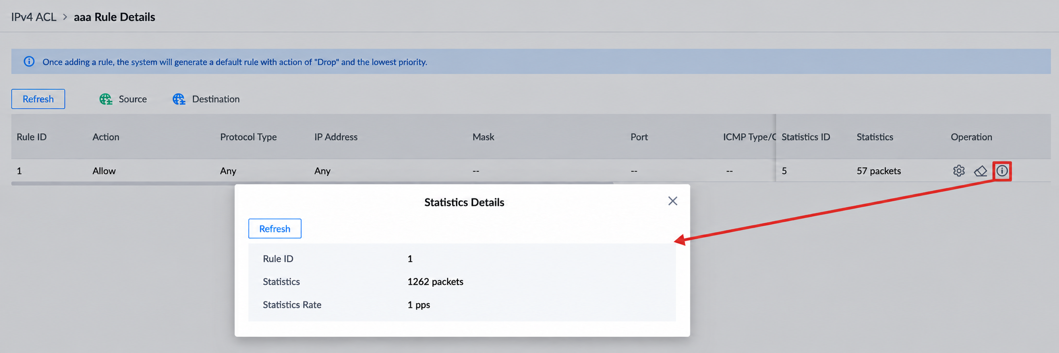
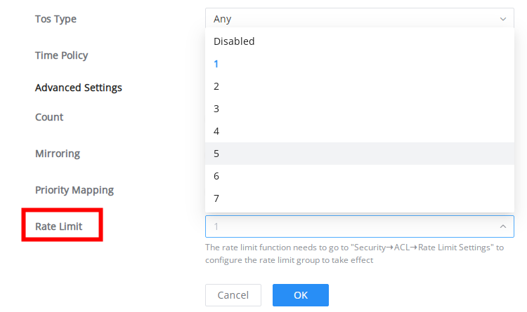
Configuring an ACL-based RSPAN
To perform an ACL-based RSPAN, please follow the below steps:
- Select an image group in ACL Image
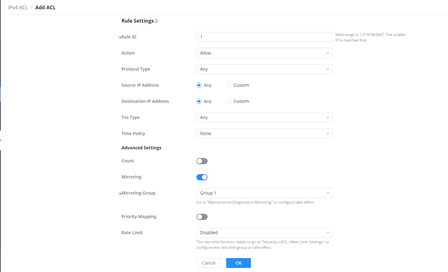
- Then, under ACL →VLAN Binding ACL, select the corresponding port/VLAN binding ACL.
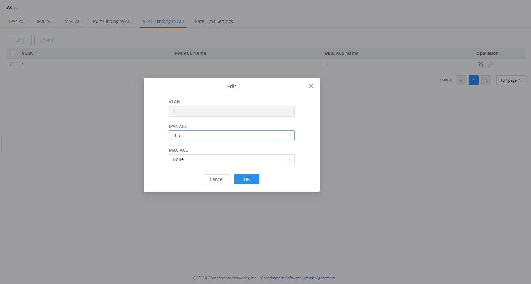
- Then go to Diagnostics → Mirroring → Setup Mirroring Group. If you select RSPAN, you can only use it as a source switch and you need to set the output port and remote VLAN.
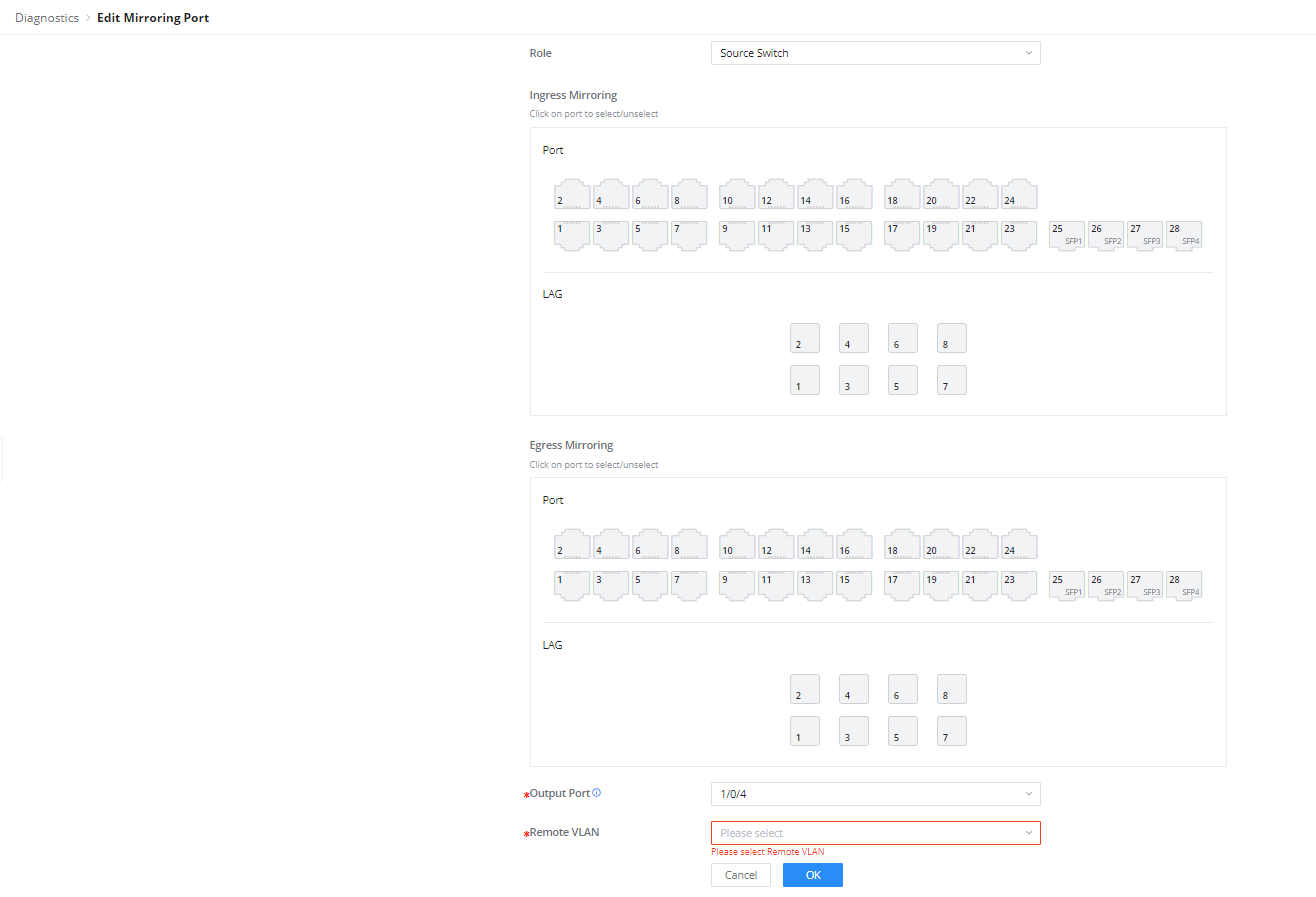
MAC ACL
To add an ACL based on the MAC address, on the MAC ACL tab, click on the “Add” button to add an ACL rule, then configure the Source MAC Address and the Destination MAC Address accordingly. Please refer to the figure below:

Port Binding to ACL
ACL Binding lets the user bind MAC ACL or IP ACL to certain ports GE/LAG.
To apply IP/MAC ACL rules on multiple ports, select the ports first then click on the “Edit” button, then select the IP and MAC ACL rule from the drop-down list.
To apply the ACL rule on a specific port, click on the “Edit icon” on the right side of the page as shown below:

VLAN Binding to ACL
On this page, the users can bind the IP/MAC ACL rule to a VLAN(s), to apply the ACL rules to multiple VLANs, first check the VLANs from the list then click on the “Edit” button, select the ACL rule from the drop-down list under IP/MAC ACL.
For example: if the IP/MAC ACL rule is configured with a rate limit, and then bound to a VLAN, the bandwidth limit will be applied to the specified VLAN.
refer to the figure below:

Rate Limit Settings
The Rate Limit Settings section in ACL (Access Control List) allows users to configure rate limiting for up to 128 groups. Rate limiting helps manage and control the amount of traffic sent or received on the network, preventing congestion and ensuring fair usage. This feature is crucial for maintaining optimal network performance and avoiding overloads.

The users can configure up to 128 groups, by clicking on the “Edit icon” under the operation column.
- Click on the “Edit icon” under the Operation column to configure a group.
- Select the Rate Limit Type to determine if the limit will be by packet or byte.
- Specify the Burst Packet/Byte, which sets the maximum number of packets or bytes allowed to be sent in a burst.
- For By packet, set Rate Threshold (pps) from 1 to 262143. For By byte, set Rate Threshold (KBps) from 2 to 125000 in multiples of 2.

IP Source Guard
IP source guard is a source IP address filtering technology based on the Layer 2 interface. It can prevent malicious hosts from forging IP addresses of legitimate hosts to impersonate legitimate hosts, and also ensure that unauthorized hosts cannot access by specifying their IP addresses. network or attack the network. IPSG uses the binding table (source IP address, source MAC address, VLAN to which it belongs, and the binding of the inbound interface ) to match and check the IP packets received on the Layer 2 interface. Only the packets matching the binding table are allowed to pass through.
To enable IP Source Guard, first navigate to the Security → IP Source Guard page, then select the port and click on “Edit” to configure the port.

Then, select the Verification Type where either the verification will be based on IP addresses or both IP and MAC addresses. Max Entries limits the number of IP/MAC addresses (e.g. devices) where 0 indicates no limit.

This page displays the dynamic binding (port, IP, MAC, VLAN) generated when DHCP Snooping is enabled on the GWN780x switches, also the user can add static binding by clicking on the “Add” button as shown below:
To import or export the list click on the import or export button respectively.

The binding requires specifying the port, IP Address and its mask, MAC address and its mask, and the VLAN ID. This information will be used to verify the traffic and make sure all the traffic is generated by legitimate users.
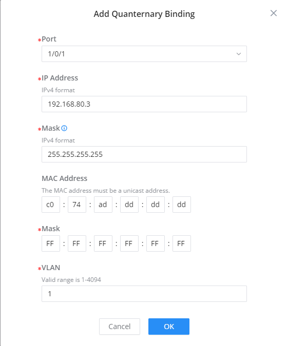
IPv6 Source Guard
IPv6 Source Guard is similar to IP Source Guard (based on IPv4), the only difference is that IPv6 Source Guard filters IPv6 addresses.

To enable IPv6 Source Guard on a port, select the port and click on the “Edit” button under the operation column, then select the Verification Type and specify the Max Entries.
On this tab, the user can see the list of binding both static and dynamic (DHCP Snooping must enabled).
To add a static entry, click on the “Add” button, it’s also possible to import or export the list as shown below:

Specify the binding (port, IP address, MAC Address, and VLAN), then click on the “OK” button to save.
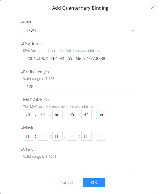
Anti Attack
In the network, there are a large number of malicious attack packets targeting the CPU and various types of packets that need to be normally sent to the CPU. Malicious attack packets targeting the CPU will cause the CPU to be busy processing attack packets for a long time, thereby causing interruption of other services or even system interruption; a large number of normal packets will also lead to high CPU usage and performance degradation, thus affecting the normal business.
In order to protect the CPU and ensure that the CPU can process and respond to normal services, the switch provides a local attack defense function, which is aimed at the packets sent to the CPU. It operates normally to avoid the mutual influence of various services when the device is attacked.
Attack defense is an important network security feature. It analyzes the content and behavior of the packets sent to the CPU for processing, determines whether the packets have attack characteristics, and configures certain preventive measures against the packets with attack characteristics. Defense attacks are mainly divided into malformed packet attack defense, fragmented packet attack defense, and flood attack defense.
Land blocks malformed packets whose source and destination IP addresses and ports are identical. Under TCP Attack, select the illegal TCP flag combinations to detect, including SYN-RST, SYN-FIN, X-Mass Scan, SYN Nonack Sport, and Null Scan.
Under ICMP Ping, select IPv4, IPv6, or both. Additional controls include SMAC=DMAC, IPv4 Ping of Death, ICMP Fragment, IPv6 Min Fragment, TCP Fragment, and TCP Min Hdr. Enabling Smurf Attack displays Netmask Length from 0 to 32. Enabling IPv6 Min Fragment displays Minimum Fragment (Byte) from 0 to 65535.

Dynamic ARP Inspection (DAI)
To defend against man-in-the-middle attacks and prevent data of legitimate users from being stolen by the man-in-the-middle, you can enable dynamic ARP inspection. The device compares the source IP, source MAC, interface, and VLAN information corresponding to the ARP packet with the information in the binding table. If the information matches, it means that the user who sent the ARP packet is legitimate, and the user is allowed. If the ARP packet passes, otherwise it is considered an attack and the ARP packet is discarded.
Dynamic ARP inspection can be enabled in the interface view, or VLAN view. When enabled in the interface view, the binding table matching check is performed on all ARP packets received by the interface; when enabled in the VLAN view. Then, the binding table matching check is performed on the ARP packets belonging to the VLAN received by the interface that joins the VLAN.
When the device discards a large number of ARP packets that do not match the binding table, if you want the device to alert the network administrator in the form of an alarm, you can enable the dynamic ARP inspection discarded packet alarm function. When the number of discarded ARP packets exceeds the alarm threshold, the device generates an alarm.
Under Security → DAI, edit a port to configure its verification and rate-limiting behavior. Use a nonzero Rate (pps) to enforce a packet-rate limit, then choose the action for traffic exceeding that limit. A rate of zero disables rate limiting, so the selected rate-limit action does not take effect.
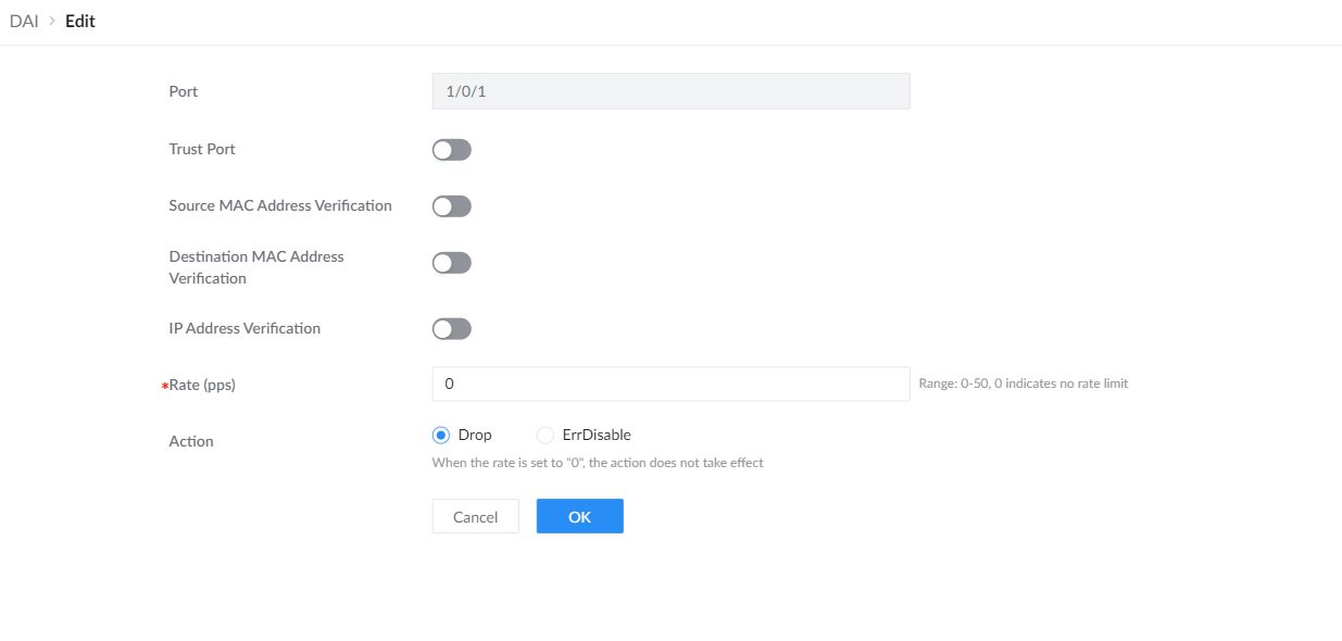
| Trust Port | Mark trusted interfaces according to the network’s DAI design. Keep untrusted client-facing interfaces subject to inspection. |
|---|---|
| Source / Destination MAC Address Verification | Enable the required MAC-address verification checks for received ARP traffic. |
| IP Address Verification | Enable IP-address verification for received ARP traffic. |
| Rate (pps) | Set the permitted ARP packet rate. Zero means no rate limit. |
| Action | Drop discards packets exceeding the configured nonzero rate. ErrDisable places the port into an error-disabled state when the limit is exceeded. |
The Statistics tab reports forwarded packets, verification failures, and Rate-limited Dropped Packets for each port. Use Refresh to retrieve current counters or Clear to reset the selected counters.
RADIUS
RADIUS centralizes authentication, authorization, and accounting. A RADIUS server group is a named collection of one or more authentication servers and accounting servers. After creating it, select the group name in AAA or another supported feature.
Under Security → RADIUS, click Add and enter the group name. Configure the authentication destinations under Authentication Server and the accounting destinations under Accounting Server. Use Add within either tab to add more servers to the same group.
Authentication Server
Use the Authentication Server tab to define the RADIUS servers that process authentication and authorization requests for this group. Configure the first server, then click Add to include additional authentication servers in the same named group.
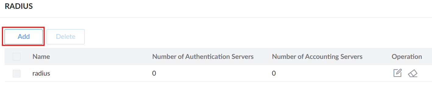
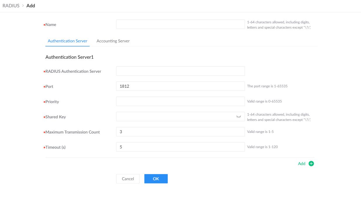
| Name | Enter a name for the server group. A RADIUS server group is a named collection of authentication and accounting servers that can be selected later in AAA or another supported feature. |
|---|---|
| RADIUS Authentication Server | Enter the address of a server that processes authentication and authorization requests for the group. |
| Port | Set the destination UDP port. The initial authentication value is 1812. |
| Priority | Set this server’s priority within the group. |
| Shared Key | Enter the secret configured for this switch on the RADIUS server. The values must match. |
| Maximum Transmission Count | Set the maximum number of transmissions for a request. |
| Timeout (s) | Set how long the switch waits for a server response. |
| Add | Add another authentication server to the same group. |
Accounting Server
Open Accounting Server to configure the destinations that receive accounting records. The group keeps authentication and accounting servers in separate lists.
| RADIUS Accounting Server | Enter the address of a server that receives accounting records for the group. |
|---|---|
| Port | Set the destination UDP port. The initial accounting value is 1813. |
| Priority | Set this server’s priority within the group. |
| Shared Key | Enter the matching RADIUS shared secret. |
| Maximum Transmission Count | Set the maximum number of transmissions for a request. |
| Timeout (s) | Set how long the switch waits for a server response. |
| Add | Add another accounting server to the same group. |
TACACS+
TACACS+ provides centralized authentication, authorization, and accounting for switch management access. A TACACS+ server group is a named collection of one or more TACACS+ servers. After creating the group, select its name in an AAA method to use those servers.
Add a TACACS+ Server Group
Open Security → TACACS+ and click Add. Enter a name for the group and configure the first server shown in the form. Click Add inside the form to include another server in the same group, then confirm the group when its server list is complete.

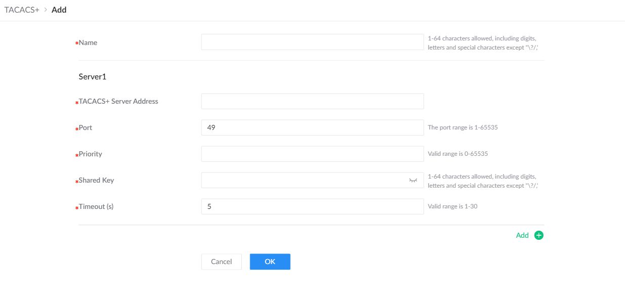
| Name | Enter a name for the server group. This name identifies the collection of TACACS+ servers when selecting it in an AAA method. |
|---|---|
| TACACS+ Server Address | Enter the address of a TACACS+ server in this group. |
| Port | Set the destination TCP port. The initial value is 49. |
| Priority | Set this server’s priority within the group. |
| Shared Key | Enter the secret configured for this switch on the TACACS+ server. The values must match. |
| Timeout (s) | Set how long the switch waits for a server response. |
| Add | Add another TACACS+ server to the same group. |
AAA
Authentication, Authorization, and Accounting (AAA) controls management access. RADIUS and TACACS+ server groups are created separately and are reusable. In AAA, create ordered method lists that reference the required local method or configured server group, then assign each method list to the applicable management access type.
When adding or editing a method list, configure the ordered Method 1, Method 2, Method 3, and Method 4 fields. Keep a working local recovery method while testing external authentication.
When adding or editing a method list, configure the ordered Method 1, Method 2, Method 3, and Method 4 fields. Keep a working local recovery method while testing external authentication.
The same method-list workflow is used on the Login Authentication, Session Authorization, and Session Accounting tabs. Select the required tab, create an ordered method list, then assign that list to the supported management access types shown on the tab.
The following matrix shows which AAA services are supported for each management access type. The web interface documented below provides the Login Authentication, Session Authorization, and Session Accounting tabs.
| Access Type | Login Authentication | Session Authorization | Command Authorization | Session Accounting | Command Accounting |
|---|---|---|---|---|---|
| Console | Supported | Supported | Supported | Supported | Supported |
| Telnet | Supported | Supported | Supported | Supported | Supported |
| SSH | Supported | Supported | Supported | Supported | Supported |
| HTTPS | Supported | Supported | Not supported | Not supported | Not supported |
Warning: A failed external method can make the switch inaccessible. Keep a verified recovery method while testing AAA changes.
Configure an AAA Method
On the required AAA tab, click Add in the Method area. The access-type selectors above the method table are used to assign an existing method list.
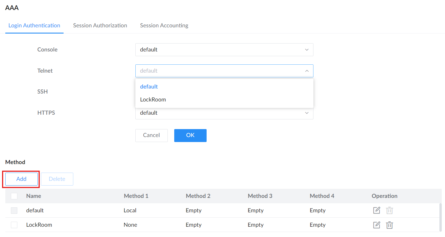
Enter a method-list name and define the order of Method 1 through Method 4. The switch evaluates the configured positions in order.
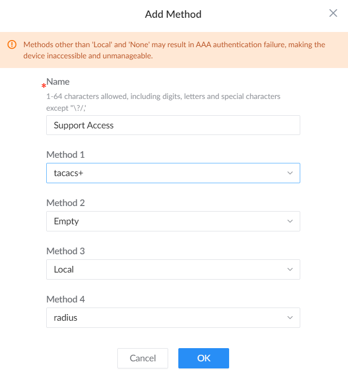
For each position, choose the required local option or a configured RADIUS or TACACS+ server group. Positions that are not required can remain empty.
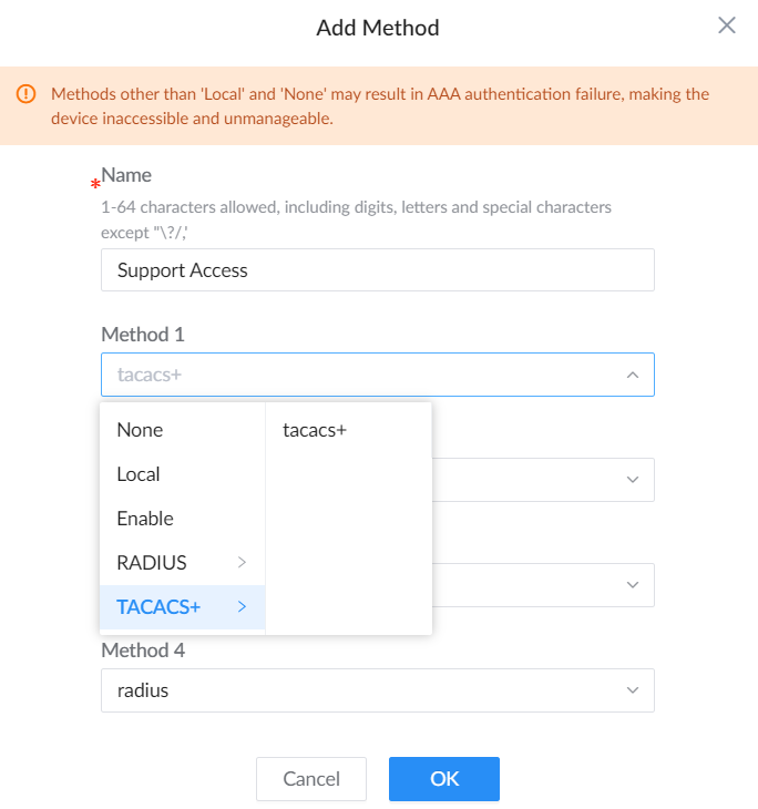
After the method list is available in the table, select it for each supported management access type that should use it.
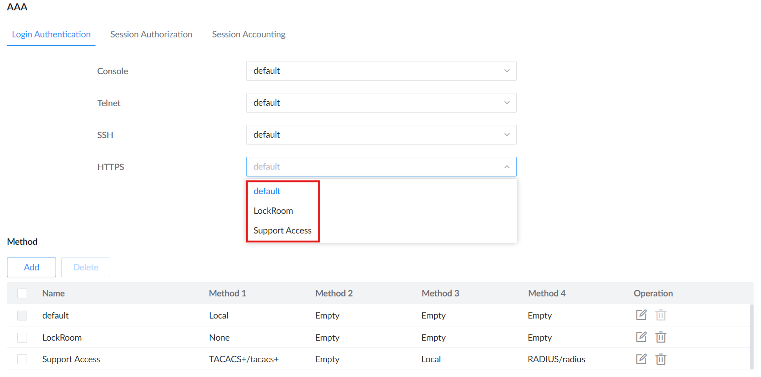
Login Authentication
Use this tab to create an ordered login-authentication method list and assign it to Console, Telnet, SSH, or HTTPS. The shared workflow above shows how to create the list, select local or configured RADIUS/TACACS+ methods, and assign the completed list.
| Name | Identifies the reusable login-authentication method list. |
|---|---|
| Method 1-4 | Set the ordered authentication methods. Select a configured RADIUS or TACACS+ group when external authentication is required. |
| Console / Telnet / SSH / HTTPS | Assign a login-authentication method list to each management access type. |
Session Authorization
Create an ordered authorization method list and assign it to Console, Telnet, SSH, or HTTPS. Select the required configured RADIUS or TACACS+ group in a Method entry.
| Name | Identifies the reusable session-authorization method list. |
|---|---|
| Method 1-4 | Set the ordered authorization methods. Select a configured RADIUS or TACACS+ group when external authorization is required. |
| Console / Telnet / SSH / HTTPS | Assign a session-authorization method list to each management access type. |
Session Accounting
Create an accounting method list and assign it to Console, Telnet, or SSH. HTTPS does not support session accounting. Select the configured RADIUS or TACACS+ group that will receive the records.
| Name | Identifies the reusable session-accounting method list. |
|---|---|
| Method 1-4 | Set the ordered accounting methods. Select a configured RADIUS or TACACS+ group for external accounting. |
| Accounting Mode | Select Start&End, End Only, or None according to the records required by the accounting server. |
| Console / Telnet / SSH | Assign a session-accounting method list to each supported management access type. |
| Real-time Accounting Interval (s) | Set the periodic accounting-update interval from 0 to 3,932,100 seconds. A value of 0 disables periodic updates. |
Identity Authentication Management
The Identity Authentication Management feature on Grandstream GWN switches provides a robust method for securing network access through 802.1X and MAC-based authentication. It allows administrators to configure and manage user authentication settings, ensuring only authorized devices can connect to the network, thereby enhancing overall network security and control.
The 802.1X protocol is a port-based network access control protocol. Port-based network access control refers to verifying user identities and controlling their access rights at the port level of LAN access devices. The 802.1X protocol is a Layer 2 protocol and does not need to reach Layer 3. It does not require high overall performance of the access device, which can effectively reduce network construction costs. Authentication packets and data packets are separated by logical interfaces to improve security.
Port Mode
To enable 802.1x and MAC authentication, please navigate to Security → Identity Authentication Management, then Toggle on “802.1X Authentication” and “MAC Authentication“, and click on the “OK” button to save.
On this page also, you can specify a user ID format for MAC-based and enable a Guest VLAN. This ensures these devices remain isolated from the main network while still maintaining limited network connectivity through the Guest VLAN. The Guest VLAN ID directs unauthenticated users to a designated network segment, providing controlled and secure access.

To enable it on a port, select the port or ports from the list, then click Edit or the row edit icon. The Authentication Type / Method column identifies the authentication mechanism and method applied to each port, such as 802.1X or MAC-based authentication.
Note: a RADIUS server must first be added under Security → RADIUS.

Port | The specific port being configured. This field shows the port number (e.g. |
User Authentication Mode | The mode of user authentication to be used on this port. Options include: MAC-Based |
Guest VLAN | Enables or disables the Guest VLAN for this port. If enabled |
Authorized VLAN | Specifies the VLAN ID that authenticated users will be assigned to. This ensures that authorized devices are placed in the correct network segment. |
Authentication Methods(x) Note: click on “Add+” to add another method. | |
Authentication Method1 | Select the authentication method, two options:
|
Method | • If MAC Authentication is selected, the user can add two methods: Radius and Local. • If 802.1x is selected, the user can only select radius. Note: When Radius is selected, the switch includes the Calling-Station-Id attribute in the Access-Request message, containing the MAC address of the connected device. This allows RADIUS servers to apply identity-based policies and track client devices using their hardware address. |
Port Mode – Edit port
Port
On this tab, the users can enable on which ports the authentication will take effect, select the port(s) and then click on “Edit” button or icon to configure the port(s) as shown below:

To enable the authentication on the port(s), under Port Control (Disable, Force authentication, Force unauthentication, Auto) select Auto or Force authentication and then save the configuration.

Example of 802.1X configuration on GXV3480 IP Video phone.
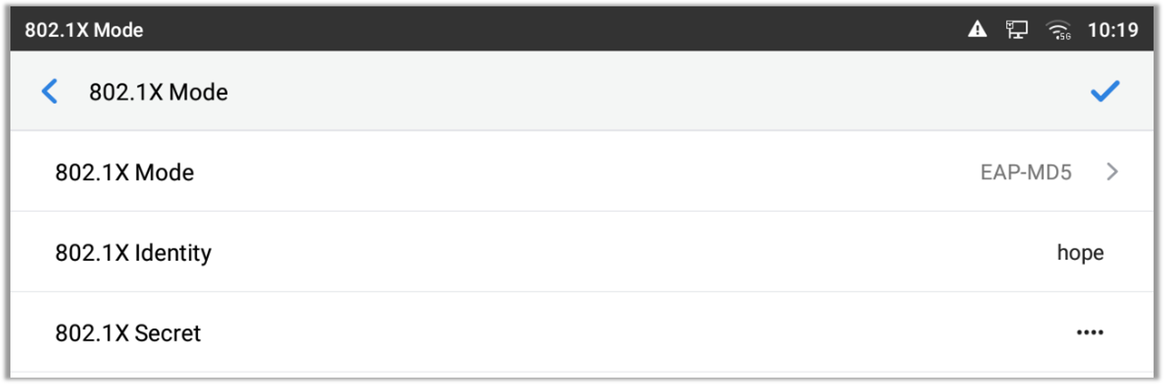
Authentication Sessions
The Authentication Sessions tab lists authenticated devices and their session details. Use the Session ID/Port/MAC Address search field to filter sessions by session ID, port, or MAC address.

There are three status (Authorized, Locked, Guest):
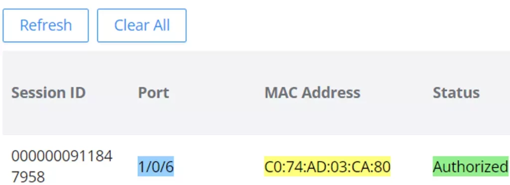


Local User of MAC-based
When MAC Authentication is enabled on Port Mode, use User ID format of MAC-based to select the MAC-address format supplied as the user ID.
When MAC Authentication is enabled on Port Mode, use User ID format of MAC-based to select the MAC-address format supplied as the user ID.
Use Security → Identity Authentication Management → Local User of MAC-based to manage local MAC-based access entries. Click Add to define an entry. Use Name to identify the device, such as an office printer, without having to recognize its MAC address.
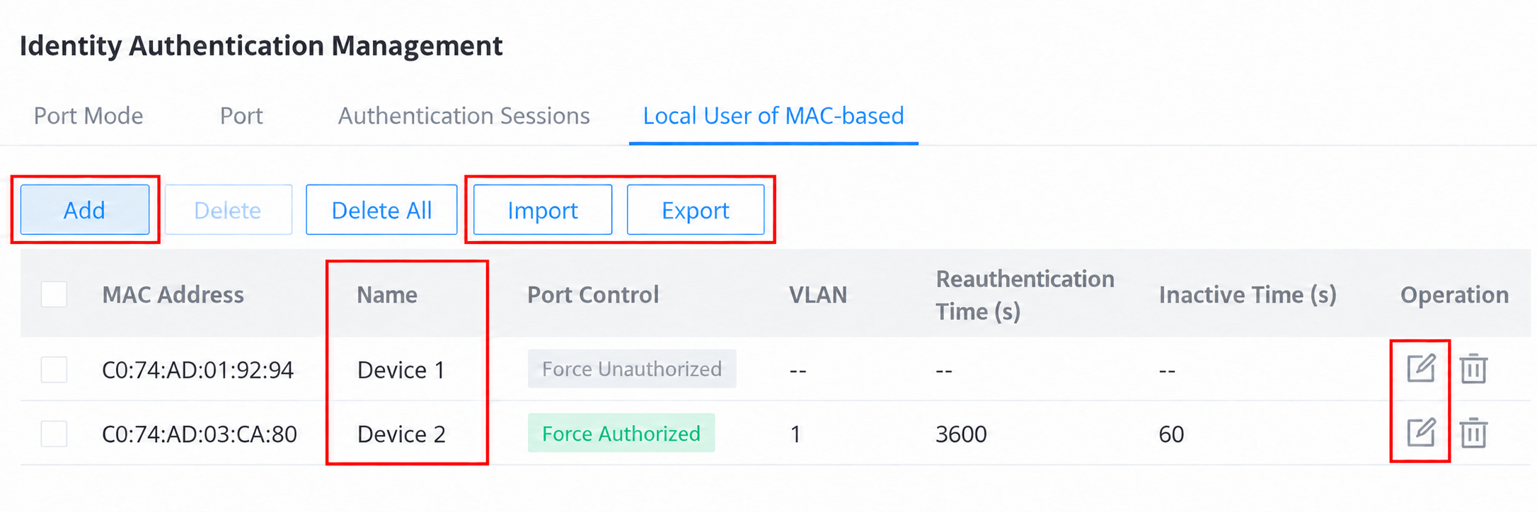
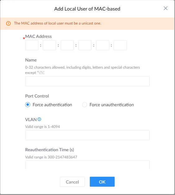
| MAC Address | Enter the local device’s unicast MAC address. |
|---|---|
| Name | Enter an optional descriptive name of up to 32 characters to identify the device in the local-user list. |
| Port Control | Force authentication authorizes the specified device; Force unauthentication denies it access. |
| VLAN | Specify the VLAN for the local user. |
| Reauthentication Time (s) | Set the interval for reauthentication in seconds. |
| Inactive Time (s) | Set the permitted inactivity time in seconds. |
To add entries from a file, click Import and download the Reference Template. Fill in the CSV using that template, select it under Upload CSV File, and click OK. Use Export from the local-user list to download the existing entries.
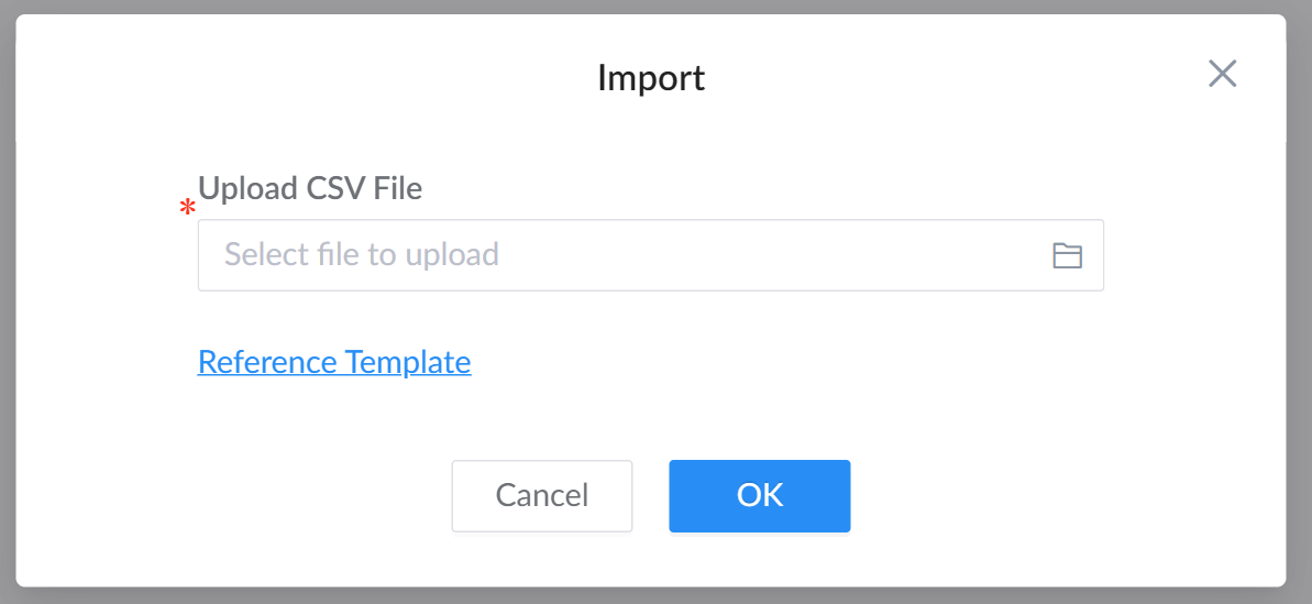
ND Snooping
ND Snooping monitors IPv6 Neighbor Discovery traffic to establish address-to-port bindings used by related security features such as IPv6 Source Guard. Open Security → ND Snooping to select the VLANs and address types to inspect, then configure port trust and validation according to the network design.
Global Settings
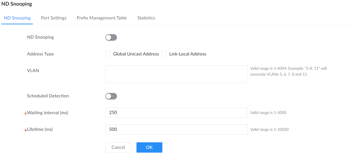
| ND Snooping | Enable or disable the feature globally. |
|---|---|
| Address Type | Select Global Unicast Address, Link-Local Address, or both. |
| VLAN | Specify the VLANs to inspect. Individual IDs and ranges can be combined, for example 5-8,11. |
| Scheduled Detection | Enable scheduled detection to expose Detection Count and Detection Interval. |
| Detection Count / Detection Interval (ms) | Configure the number of detection attempts and the time between attempts when Scheduled Detection is enabled. |
| Waiting Interval (ms) / Lifetime (ms) | Configure the waiting interval and lifetime used by ND Snooping. These timing fields are independent of the scheduled-detection interval. |
Port Settings
On Port Settings, edit the required interface. Enable Trust Mode only on interfaces that carry trusted Neighbor Discovery traffic. Enable Validation Check to choose which message types to validate: NA (Neighbor Advertisement), NS (Neighbor Solicitation), and RS (Router Solicitation).
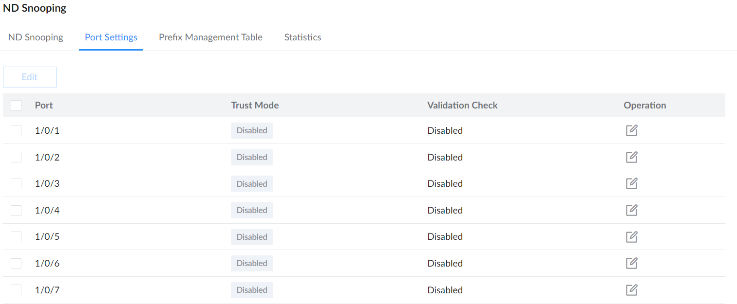
Prefix Management Table
The Prefix Management Table lists IPv6 prefixes and their VLANs. Click Add to enter an IPv6 Address, Prefix Length, and VLAN for a static entry. Use Solidify to retain a selected learned entry as a static entry.
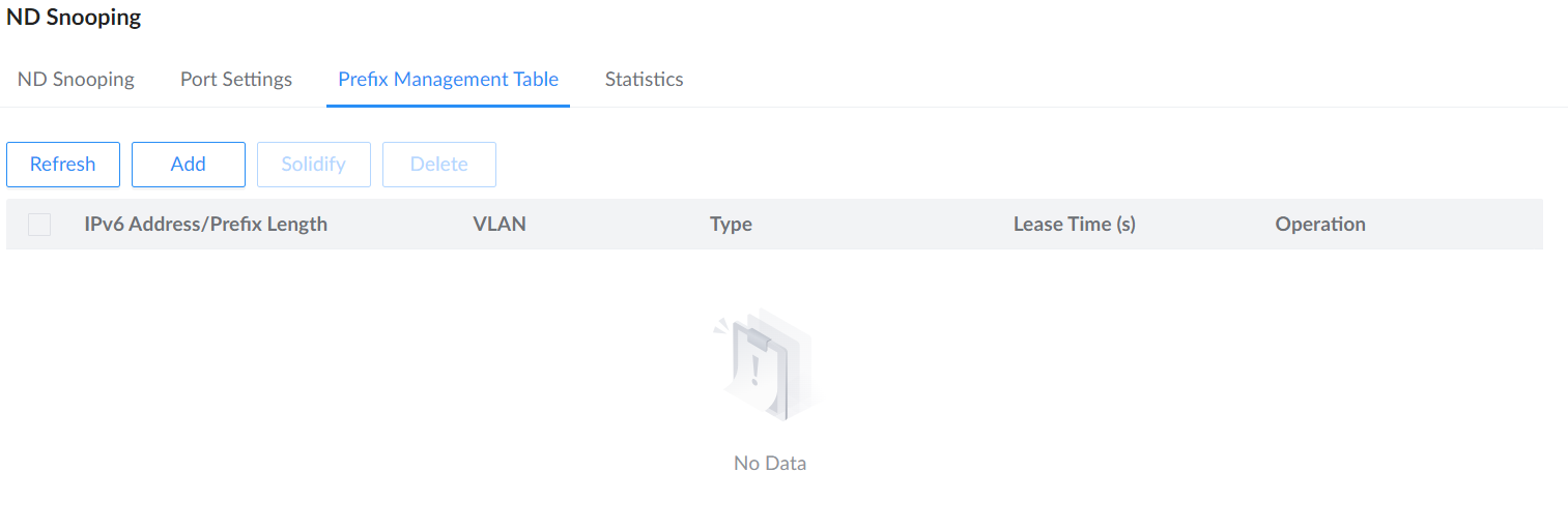
Statistics
The Statistics tab shows received Neighbor Discovery packets by message type, transmitted packets, and dropped packets for each port. Scroll the table horizontally to see the remaining counters, including Tx Packets and Dropped Packets. Use Refresh to retrieve current counters and Clear only when you intend to reset the selected counters.
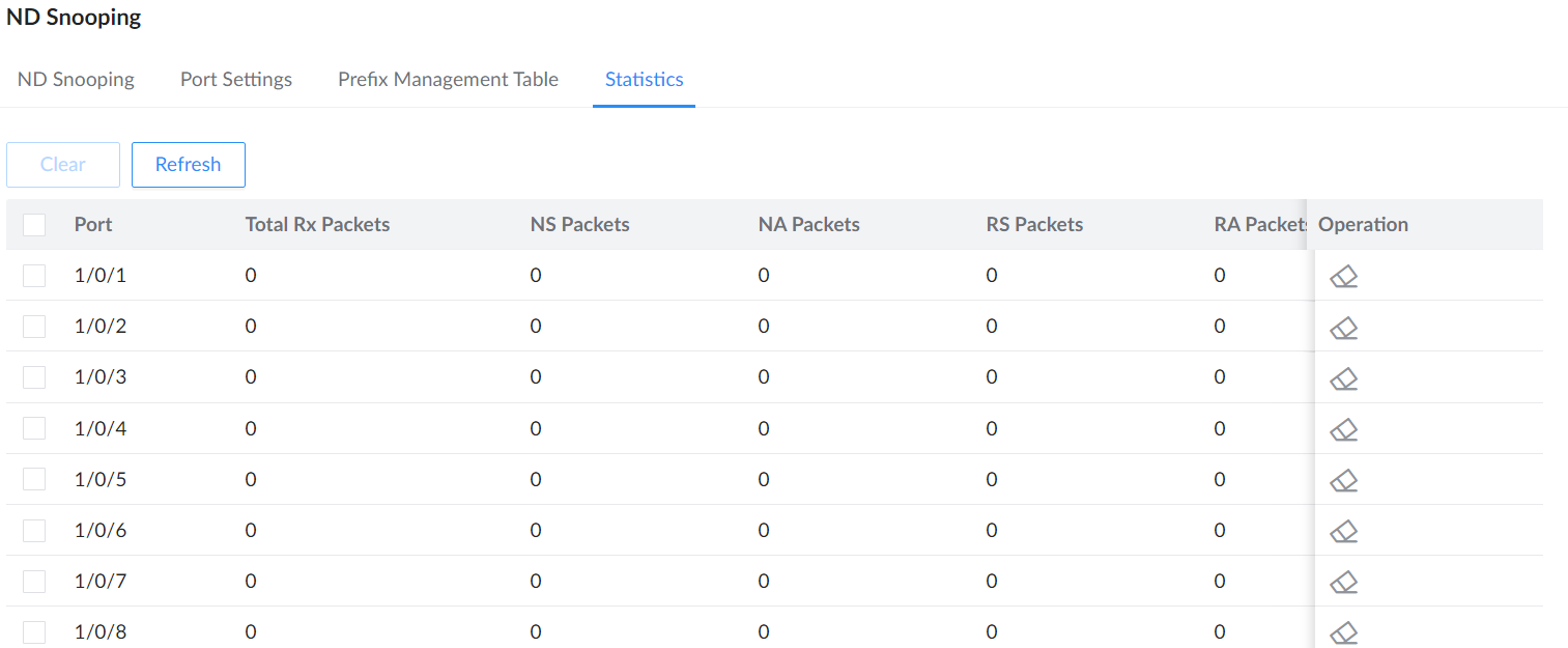
DHCP Snooping
DHCP snooping ensures that DHCP clients obtain IP addresses from legitimate DHCP servers, and records the correspondence between IP addresses and MAC addresses of DHCP clients to prevent DHCP attacks on the network.
In order to ensure the security of network communication services, the DHCP Snooping technology is introduced, and a firewall is established between the DHCP Client and the DHCP Server to defend against various attacks against DHCP in the network.
When the device reboots, the dynamic binding table for the IP source guard is automatically restored.
Entries Fixed for DHCP Snooping: Enable this option to preserve dynamic DHCP Snooping binding entries so the IP Source Guard dynamic binding table can be restored after the switch reboots. When enabled, Fixed Duration (s) sets the retention interval from 15 to 86400 seconds.
To enable the DHCP Snooping feature on GWN780x switches, navigate to Security → DHCP Snooping, then enable DHCP Snooping, to make the DHCP snooping enabled on a VLAN, specify the VLANs or a VLAN range for example 5-8 means VLANs from 5 to 8, click “OK” button to save. Please refer to the figure below:
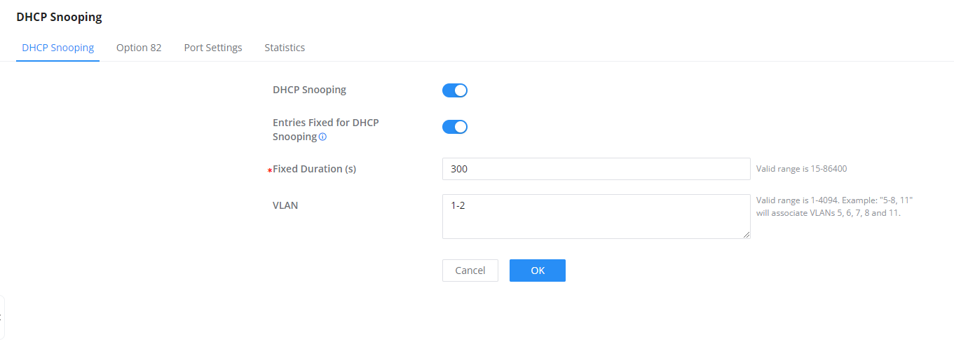
DHCP Snooping Option 82
Option 82 is called the relay agent information option and is inserted by the DHCP relay agent when forwarding client-originated DHCP packets to a DHCP server.
To identify the device accessed by the client, the user specifies the Remote ID, the format can be either Normal (standard) or Private:
- Normal Format: is generally used when interoperability between different vendors’ equipment is required, for GWN780x switches by default the MAC Address of the switch will be used, but any other characters in the range of 1-63 can be used.
- Private Format: is specific to the vendor’s ecosystem and may not be compatible with other vendors’ equipment (check the vendor-specific format).
Option 82 is used to identify both the Circuit ID and Remote ID of the specific port, this can be used to identify the VLAN, interface, and other information where the client is located. To define this information, go to DHCP Snooping → Option 82, choose a specific port:
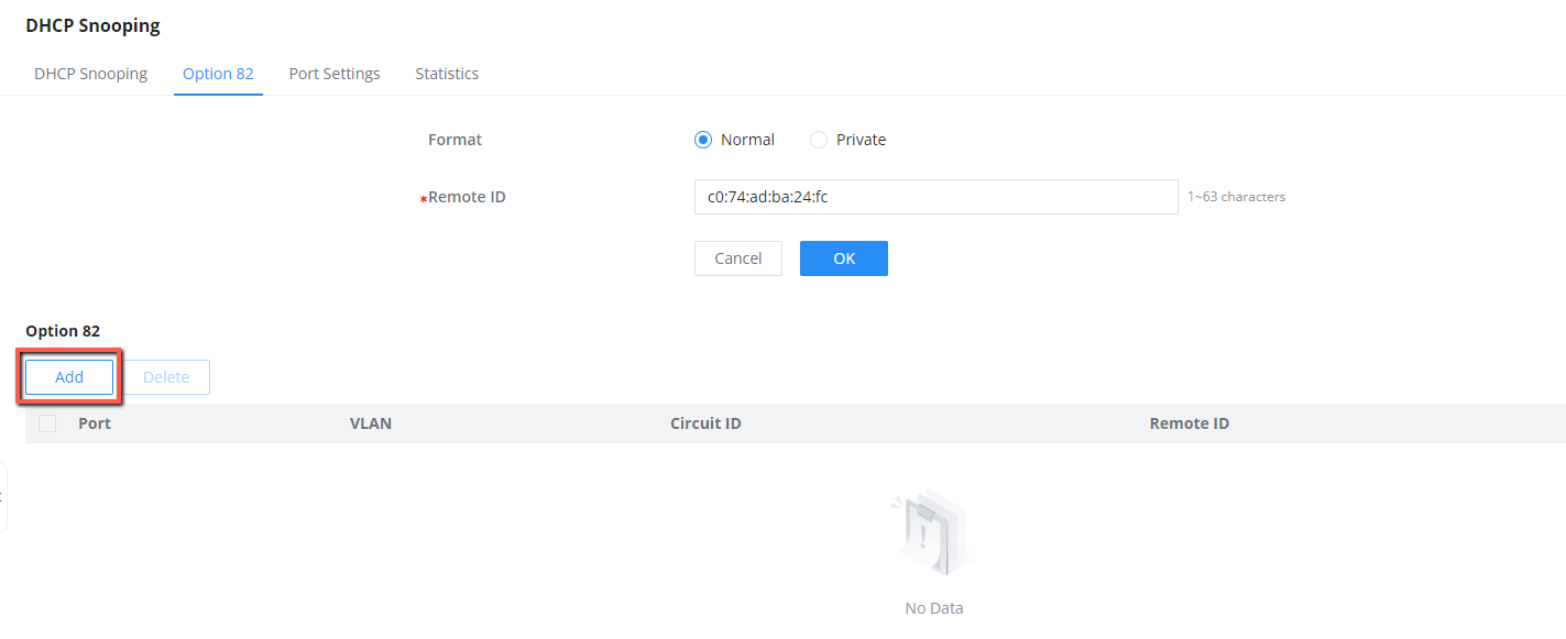
Then, select a port, VLAN and Format, and specify the Circuit ID and Remote ID:
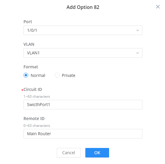
DHCP Snooping Port Settings
On this page, the user can configure the trusted port(s) that will allow DHCP messages, all other ports that are not trusted will discard the DHCP messages, this way GWN780x will protect users from rogue DHCP servers that are plugged into untrusted ports.
To configure a port(s), either select the port(s) and click on the “Edit” button or click on the “Edit icon” under the operation column as seen below:

To make a port trusted, Toggle ON Trust Mode, more security parameters can be enabled too like Chaddr Verification, Rate (pps = packet per seconds) to limit the number of DHCP packets, and enable Option 82 for this port with three modes (keep, drop, replace). Please refer to the figure below:

DHCP Snooping Statistics
This page displays all statistics recorded by DHCP snooping function including Forwarding packets, Untrusted Port Drops, etc.
To clear the statistics, select the ports and click on “Clear” button as shown below:

DHCPv6 Snooping
DHCPv6 snooping is a security feature in IPv6 networks that safeguards against unauthorized DHCPv6 server messages and controls IPv6 address assignments, similar to how DHCPv4 snooping operates in IPv4 networks.
Navigate to Security → DHCPv6 Snooping, enable DHCPv6 Snooping, and specify the protected VLANs or VLAN ranges. Enable Entries Fixed for DHCPv6 Snooping when learned DHCPv6 snooping entries must remain fixed for a controlled period. When enabled, set Fixed Duration (s) from 15 to 86400 seconds. Click OK to apply the page settings.

DHCPv6 Snooping Option 18
On this page, the user can configure the Remote ID (Option 37), by default GWN780x switches use the GWN780x switches MAC Address.
The DHCPv6 Relay-Option, encompassing Option 18 and Option 37, enables a DHCPv6 relay agent to embed circuit-specific and remote information as a TLV (type-length-value) within the relay message sent to the DHCPv6 server. In this scenario, the managed device functions as a DHCPv6 relay agent.
To add option 18 for a port, click on the “Add” button as shown below:

Then, select the port, Format (Standard, Extended), when the Standard format is selected then the user can select the VLAN and if the Extended Format is selected the user can interface ID (3~63 characters), click on “OK” to save.

DHCPv6 Snooping Port Settings
On this page, the user can configure the trusted port(s) that will allow DHCP messages, all other ports that are not trusted will discard the DHCP messages, this way GWN780x will protect users from rogue DHCP servers that are plugged into untrusted ports.
To configure a port(s), either select the port(s) and click on the “Edit” button or click on the “Edit icon” under the operation column as seen below:

To make a port trusted, Toggle ON Trust Mode, more security parameters can be enabled too like Rate (pps = packet per seconds) to limit the number of DHCPv6 packets, and enable Option 18 and 37 for this port with three modes (keep, drop, replace). Please refer to the figure below:

DHCPv6 Snooping Statistics
This page displays all statistics recorded by DHCPv6 snooping function including Forwarding packets, Untrusted Port Drops, etc.
To clear the statistics, select the ports and click on “Clear” button as shown below:

MAINTENANCE
Upgrade
Open Maintenance → Upgrade. Under Upgrade via Manual Upload, use Upload Firmware File to Update to select a supported .bin firmware file downloaded from the Grandstream Firmware page.
Under Upgrade via Network, select the Firmware Upgrade Protocol:
- TFTP
- HTTP
- HTTPS
- FTP
- Explicit FTPS
Then enter the Firmware Server Path (for example, firmware.grandstream.com). Enable Allow DHCP Option 43/160/66 to Override Server when DHCP-provided upgrade-server settings should take priority over the manually configured server.
Enable Check/Download New Firmware at Bootup to have the switch check the configured firmware server during startup and download new firmware when available. Enable Scheduled Upgrade to have the switch automatically check and upgrade during the configured schedule. Use a maintenance window because an upgrade restarts the switch and interrupts network service.
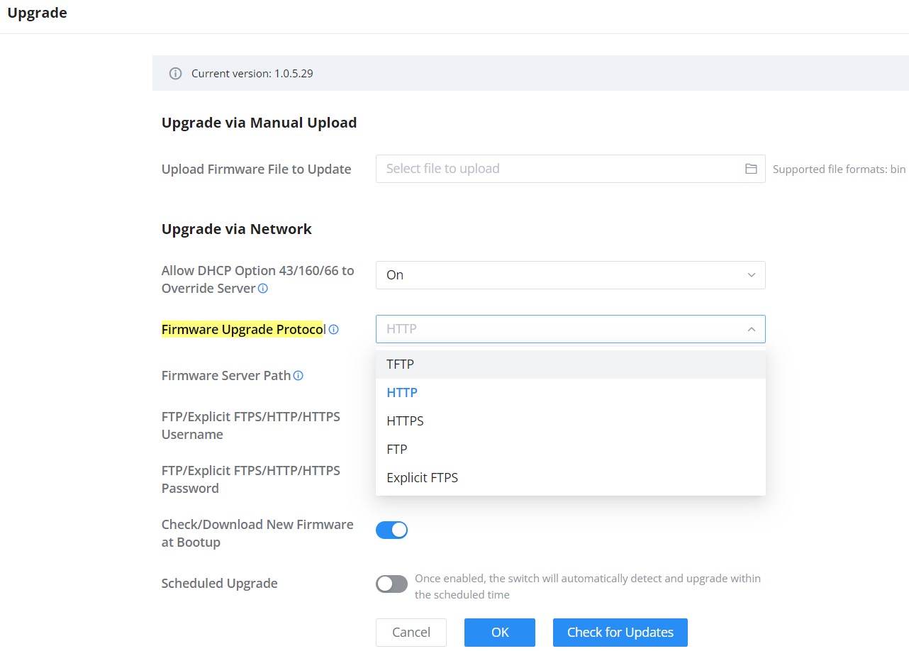
Diagnostics
GWN780x Switches support many diagnostics tools that can help the user troubleshoot the issue and resolve it. These tools include Logs, Ping, Traceroute, Mirroring, Fiber Module, Copper Test, and One-Click Debugging.
Logs
This page lists all the generated Logs with details level and generated time, also an option to export the list is available.

Adding a Log Server Address to the logs to be sent to is also supported on the GWN780x Switches.
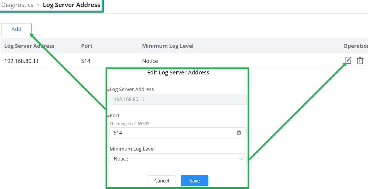
Users can Configure the following elements in the logs settings:
- Minimum log level: This defines the lowest severity of events that will be logged. “Debug” means all messages, including detailed diagnostic information, will be recorded. Other log levels (e.g., Info, Warning, Error) would filter out lower-priority messages.
- Log Aggregation: This option allows you to merge multiple logs from various sources or components into a centralized location for easier monitoring, analysis, and management.
- Timeout: This setting defines the time, in seconds, before the logging operation times out. In the example shown, the timeout is set to 60 seconds. The valid range for the timeout is between 15 and 3600 seconds.
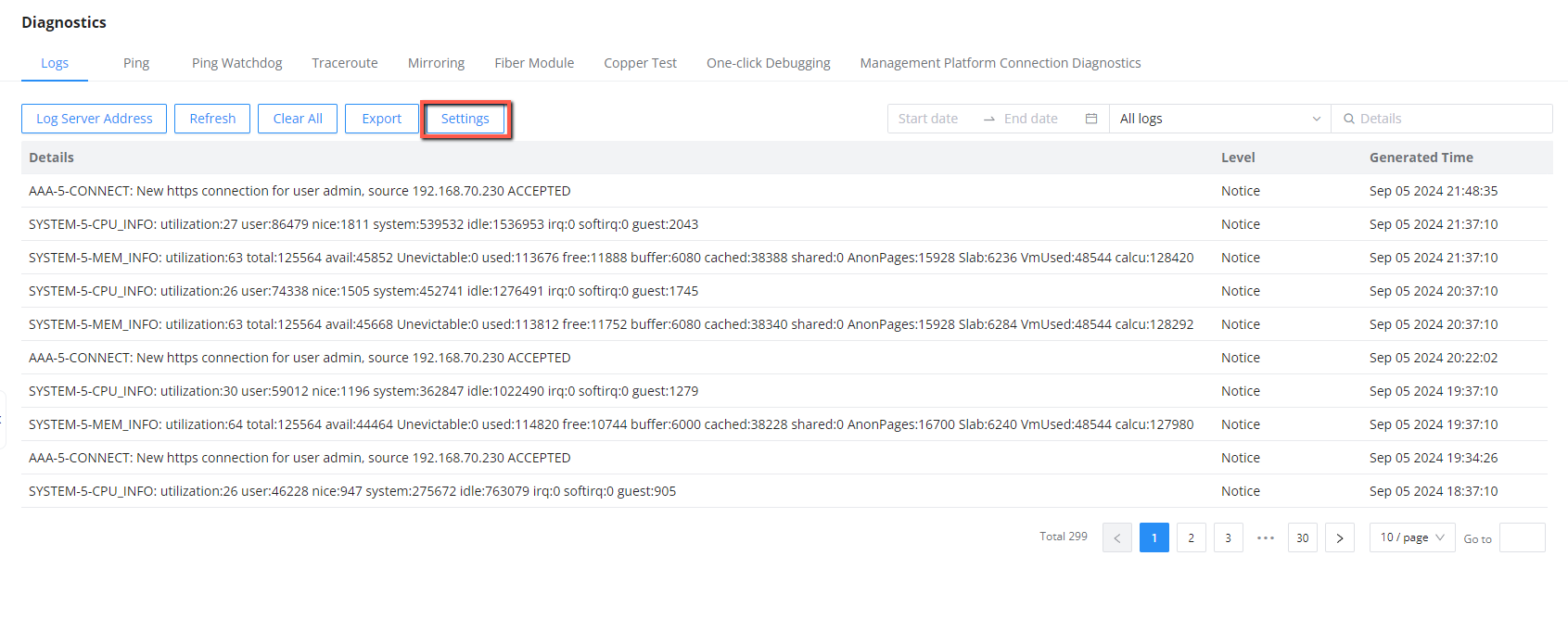
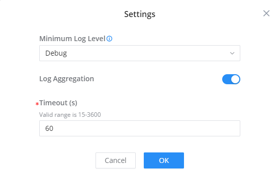
Ping
Open Maintenance → Diagnostics → Ping. Enter the destination in IP Address/Hostname, set Packet Count from 1 to 65535, and set Packet Size from 0 to 65500 bytes. Select an IP Interface when the test must use a specific Layer 3 interface, then click Start. The response and packet-loss results appear below the form.

Ping Watchdog
Ping Watchdog is a feature designed to monitor the connectivity of a device by continuously pinging a specified IP address. If the device becomes unresponsive to pings, then corrective actions can be triggered based on the configuration settings.
Port: Specifies the port on the device that will be monitored or managed by Ping Watchdog.
Enable: Toggles the Ping Watchdog feature on or off for the selected port.
IP Address: The target IP address to which the device will send ping requests.
Packet Sending Interval (s): Defines how frequently (in seconds) ping packets are sent to the specified IP address.
Delay Time (s): This sets a delay before the Ping Watchdog starts monitoring the device after it’s enabled or after a reboot.
Retry Times: Specifies how many failed ping attempts are allowed before the watchdog takes action.
Shutdown Interval (s): how long the switch keeps the port shutdown before bringing it back up after a Ping Watchdog failure.
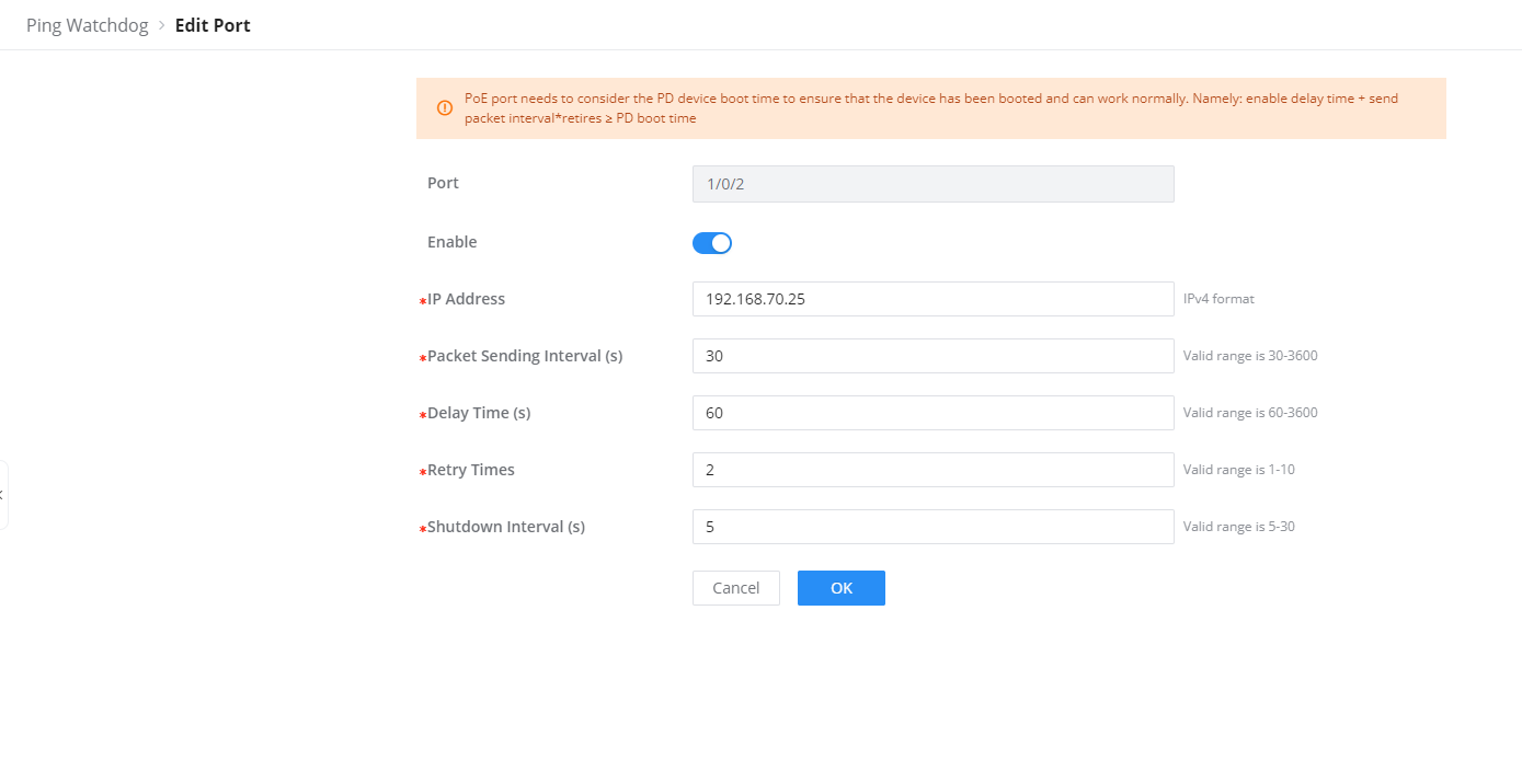
Traceroute
Another tool is Traceroute which shows the number of hops, and GWN780x Switches enables the user to run Traceroute commands right from the Switches WEB UI.
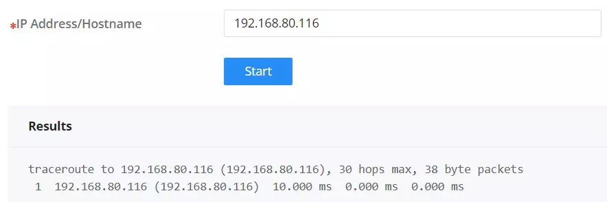
Mirroring
Mirroring refers to copying the packets from the specified source to the destination port. The specified source is called the mirroring source, the destination port is called the observing port, and the copied packet is called the mirroring packet.
Mirroring can make a copy of the original packet without affecting the normal processing of the original packet by the device, and send it to the monitoring device through the observation port to determine whether the service running on the network is normal.
The GWN780x switches support two modes of Port Mirroring: SPAN and RSPAN:
- SPAN (Local): Traffic is mirrored locally within the same switch.
- RSPAN (Remote): Traffic is mirrored remotely across a network using a Remote VLAN.
SPAN
The traffic mirroring occurs locally within the same switch. SPAN allows you to capture traffic from one or more ports and send a copy of it to another port, typically connected to a network analyzer or monitoring tool.
- Ingress Mirroring: Captures incoming traffic on the source port(s).
- Egress Mirroring: Captures outgoing traffic from the source port(s).
- Source Port: Where the traffic originates (the port being monitored).
- Tx/Rx Regular Data Messages: defines what type of traffic (transmit, receive, or both) is monitored on the destination switch.
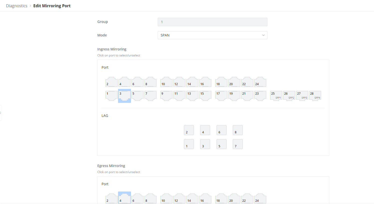
RSPAN
RSPAN (Remote Switched Port Analyzer) allows traffic to be mirrored from one switch to another over a network. Unlike SPAN, which is limited to mirroring traffic locally within the same switch, RSPAN uses a Remote VLAN to transport mirrored traffic across multiple switches, enabling centralized monitoring.
Source Switch Role (RSPAN)
- Ingress Mirroring: This captures incoming traffic on the specified source port(s). It mirrors the packets received by the port before they are processed by the switch, forwarding them to the designated destination for monitoring or analysis.
- Egress Mirroring: This captures outgoing traffic from the specified source port(s). It mirrors the packets leaving the port after the switch processes them, forwarding these packets to the monitoring destination.
- Output Port: This is the port on the source switch where the mirrored traffic is sent. In SPAN, it’s usually a local port that connects to the monitoring device, but in RSPAN, this traffic is forwarded across a network using the Remote VLAN to the destination switch.
- Remote VLAN: This is the VLAN used to transport mirrored traffic between the source switch and the destination switch in an RSPAN configuration. The source switch forwards mirrored traffic to this VLAN, which allows it to be sent across the network to the destination switch for analysis.
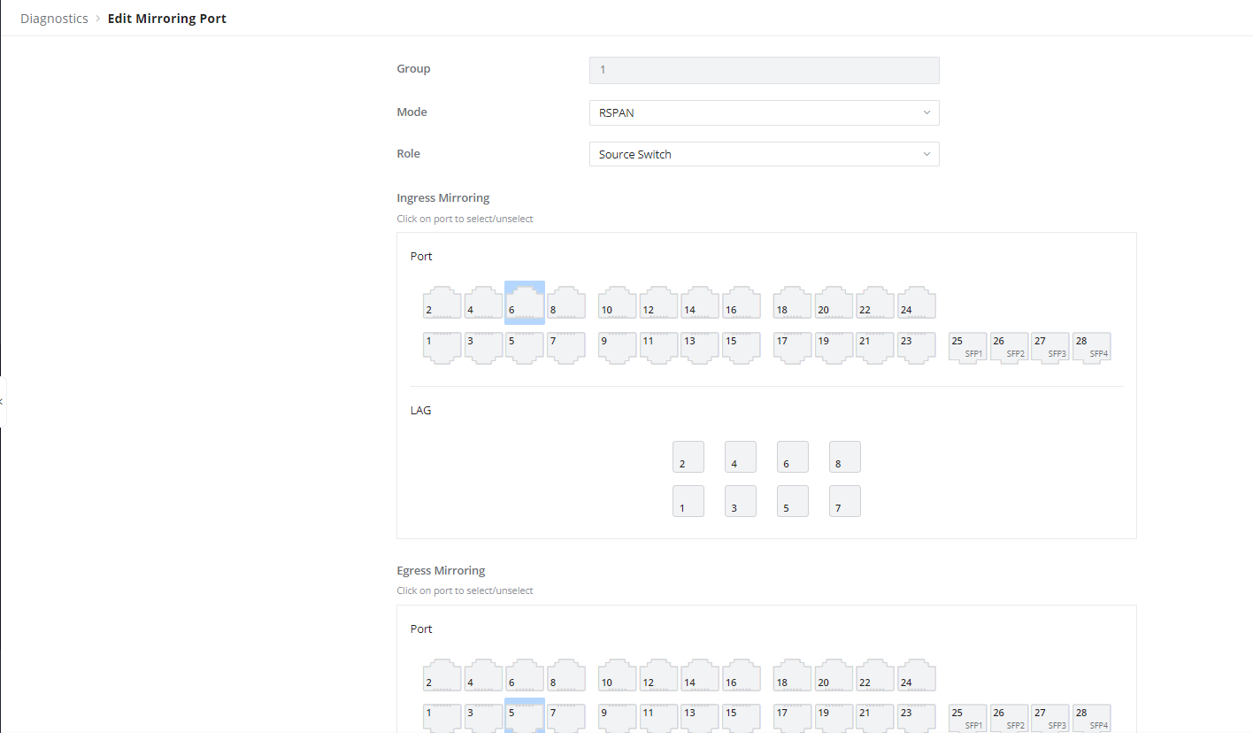
Destination Switch Role (RSPAN)
- Source Port: This is the remote VLAN where the mirrored traffic from the source switch arrives. The destination switch receives the mirrored packets via this VLAN and forwards them to the appropriate monitoring port.
- Monitor Port TX/RX: This defines what type of traffic (transmit, receive, or both) is monitored on the destination switch.
- Remote VLAN: The VLAN used to receive mirrored traffic from the source switch. It’s the same VLAN that the source switch uses to forward the mirrored traffic over the network to the destination switch.
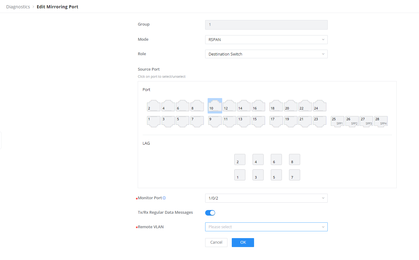
Fiber Module
This pages provides the user with the information about the fiber module for each Port that supports it. Select the port from the drop-down list and click refresh icon.
Note: The information displayed on the optical module of each manufacturer is different.

Copper Test
Copper test can detect whether the cable connected to the switch is faulty and the location of the fault. Using this function can assist in the daily engineering installation diagnosis .
Please navigate to Web UI → Maintenance → Diagnostics page → Copper Test Tab.
To perform the test simply click on the port, please refer to the figure below:

After the detection, the cable detection result is displayed as follows:
Cable Status: OK (normal), Open (open circuit), Short (short circuit ), Crosstalk (crosstalk), Unknown (unknown).
Cable Length:
- When there is a fault: it is the length from the port to the fault location.
- When there is no fault: it is the actual length of the cable.
One-click Debugging
On GWN780x switches, One-click debugging feature can help administrators or tech-support to quickly and easily get debugging information about the GWN switch in a matter of few minutes.
Please navigate to Web UI → Maintenance → Diagnostics page → One-click Debugging tab, then click on “Debug” button to start the debugging process.

It’s also possible to delete the generated file or download it locally to share it with tech-support for example. The folder contains many logs files and even a tech-support file that containing valuable information like the switch configuration etc.
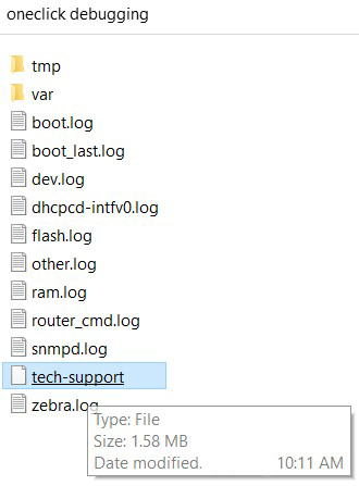
Remote Support
Remote Support temporarily authorizes Grandstream to access device diagnostic data, logs, and configuration information for troubleshooting and maintenance. Open Maintenance → Diagnostics → Remote Support, enter the administrator password, and select Remote Support only when working with an authorized support engineer. Remote access sessions are encrypted, and the feature automatically disables after 48 hours.
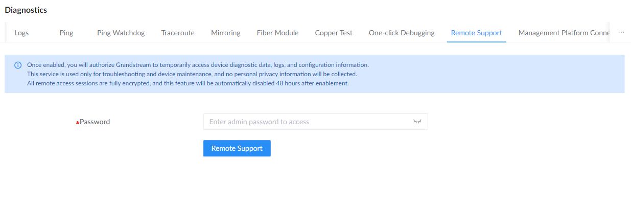
Management Platform Connection Diagnostics
Use this page to check the switch’s connection to its configured management platform and identify connection problems.
Open Maintenance → Diagnostics → Management Platform Connection Diagnostics. Select a configured Management Platform to check its Connected Status. When available, use View Log to inspect connection information for troubleshooting.
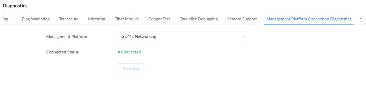
Backup and Restore
Open Maintenance → Backup & Restore. Use Back Up Running Configurations for the active configuration or Back Up Saved Configurations for the saved configuration. The backup list provides download, restore, and delete actions. Import adds a configuration file to the backup list, while Upload Configuration File is used for restoration.
Factory Reset restores factory defaults. Back up the required configuration before restoring or resetting the switch, because these operations can change network connectivity and management access.
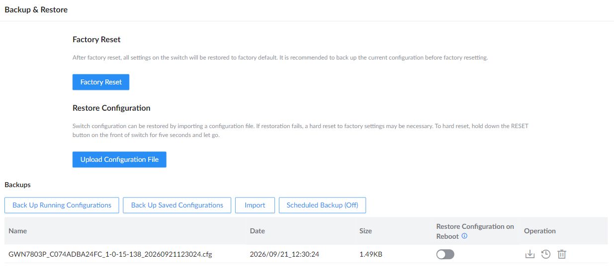
Under Maintenance → Backup & Restore, a configuration file must first appear in the Backups list. If the list is empty, use Back Up Running Configurations, Back Up Saved Configurations, or Import to add a file. Each file has a Restore Configuration on Reboot switch. Enable it for the configuration file you want the switch to restore every time it reboots. This remains in effect while the option is enabled. Verify the file’s settings before enabling it, because restoring that configuration can change network connectivity and management access.
Scheduled Backup
Under Maintenance → Backup & Restore, open Scheduled Backup and enable it to choose a Backup Time policy. Select an existing policy or use Add to define a named weekly or specific-date schedule. If weekly and specific-date schedules overlap on the same day, the specific-date schedule takes precedence.
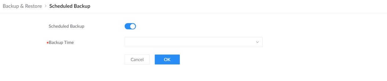
SNMP
Network Management Protocol (SNMP) is an “Internet-standard protocol for managing devices on IP networks”. Devices that typically support SNMP include routers, switches, servers, workstations, printers, modem racks and more. SNMP is used mostly in network management systems to monitor network-attached devices for conditions that warrant administrative attention. SNMP is a component of the Internet Protocol Suite as defined by the Internet Engineering Task Force (IETF). It consists of a set of standards for network management, including an application layer protocol, a database schema, and a set of data objects. An SNMP-managed network consists of three key components:
- Managed device
- Agent – software which runs on managed devices
- Network management station (NMS) – software which runs on the manager
A managed device is a network node that implements an SNMP interface that allows unidirectional (read-only) or bidirectional (read and write) access to node-specific information. Managed devices exchange node-specific information with the NMSs. Sometimes called network elements, the managed devices can be any type of device, including, but not limited to, routers, access servers, switches, bridges, hubs, IP telephones, IP video cameras, computer hosts, and printers. An agent is a network-management software module that resides on a managed device. An agent has local knowledge of management information and translates that information to or from an SNMP-specific form. A network management station (NMS) executes applications that monitor and control managed devices. NMSs provide the bulk of the processing and memory resources required for network management. One or more NMSs may exist on any managed network.
Open Maintenance → SNMP → Global Settings to enable SNMP and select SNMPv1/SNMPv2c, SNMPv3, or both. Configure the Local Engine ID and, when required, add the Remote Engine ID and server address for a remote engine.
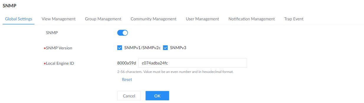
| SNMP | Enable or disable the SNMP service. |
|---|---|
| SNMP Version | Select SNMPv1/SNMPv2c, SNMPv3, or both according to the management system configuration. |
| Local Engine ID | Identify the local SNMP engine. The editable hexadecimal value must contain an even number of characters. Reset restores the initial value. |
| Remote Engine ID | Add the engine ID for a remote SNMP management entity when required by the remote-user configuration. |
| Server Address | Enter the network management station hostname, IPv4 address, or IPv6 address. |
View Management
Use View Management → Add to name a MIB view and define its Type & OID Subtree entries. Each entry includes or excludes an OID subtree. Use Add inside the view to define additional entries in the same view.
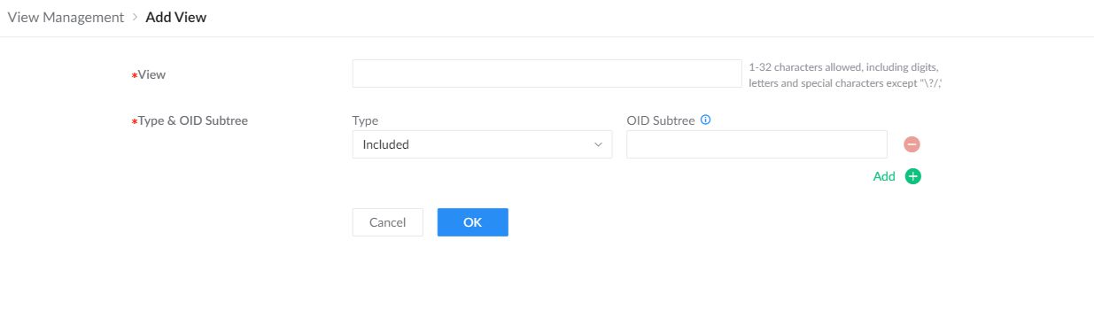
Group Management
This page allows the network administrator to group SNMP users and assign different authorization and access privileges. When adding a group, select its Read-Only View, Read-Write View, and Notification View as required.

Community Management
This page allows a user to add/remove multiple communities of SNMP.
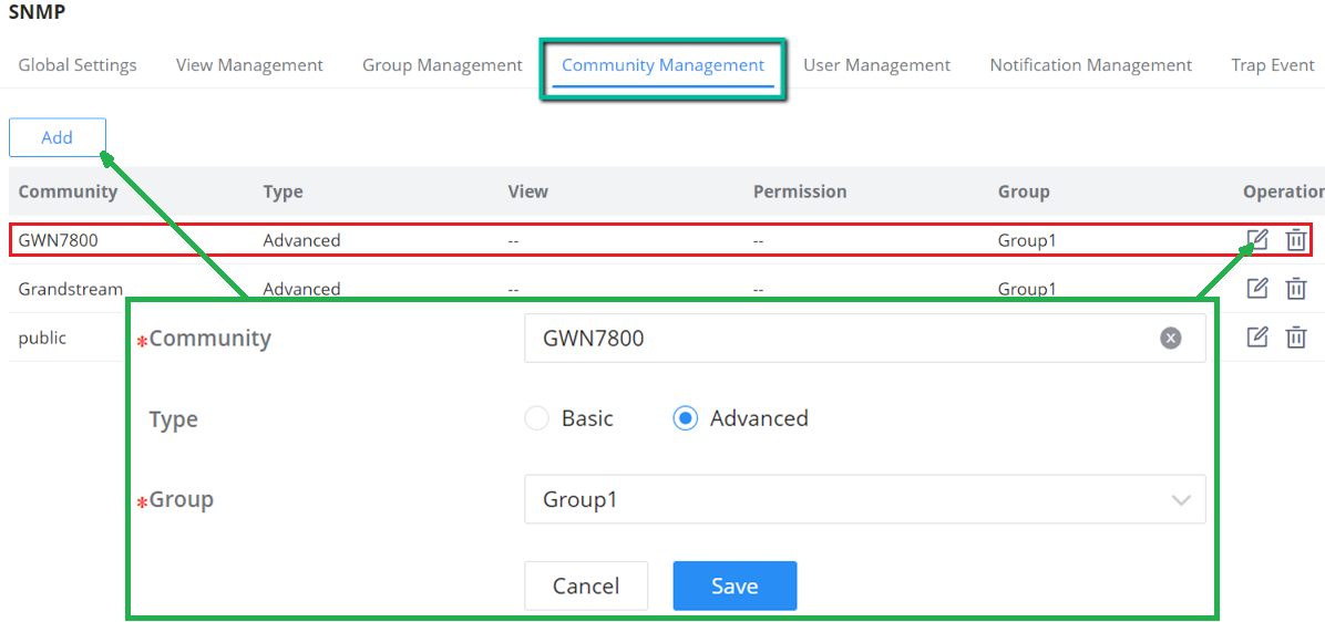
SNMP User Management
Configure SNMPv3 users under User Management after enabling SNMPv3 and defining the required group. Match the user’s security level, authentication settings, and privacy settings to the management station. The firmware adds AES as a privacy-encryption option.
Notification Management
This page allows a user to configure a host to receive SNMPv1/v2/v3 notification.

Trap Event
a Trap event refers to an alert or notification that is automatically sent by a device or system when a specific event occurs. These events, shown in the SNMP configuration, are various types of conditions that the system is monitoring. When enabled, the device sends a trap to the SNMP manager, notifying it of occurrences like:
- Authentication failed: When there is an unauthorized login attempt.
- Port Up/Down: When a network port goes offline or comes online.
- Cold Start/Warm Start: When the system or device reboots (cold or warm restart).
| Authentication failed / Port Up/Down / Cold Start / Warm Start | Send notifications for authentication failures, interface state changes, and device startup events. |
|---|---|
| STP Bridge / CPU / Monitor | Select spanning-tree, CPU, and monitoring events required by the management system. |
| Port ErrDisable / Port Security / PoE Power Supply | Report interface protection and PoE events. |
| Logs / Configuration Distribution | Select log and configuration-distribution notifications. |
| ARP Notification / Fiber Module Alert | Report ARP and optical-module alert events. |
Additional Trap Event selections include Monitor, ARP Notification, and Fiber Module Alert. Enable the events required by the monitoring system and configure the receiving host under Notification Management.
RMON
RMON (Remote Monitoring) based on SNMP (Simple Network Management Protocol) architecture, functions to monitor the network. RMON is currently a commonly used network management standard defined by the Internet Engineering Task Force (IETF), which is mainly used to monitor the data traffic across a network segment or even the entire network to enable the network administrator to take protection measures in time to avoid any network malfunction. In addition, RMON MIB records network statistics information on network performance and malfunction periodically, based on which the management station can monitor the network at any time effectively. RMON is helpful for network administrators to manage the large-scale network since it reduces the communication traffic between the management station and the managed agent.
RMON Statistics
Ethernet statistics function ( corresponding to the statistics group in the RMON MIB): The system collects basic statistics of each network being monitored. The system will continuously count the traffic of a certain network segment and the distribution of various types of packets, the number of error frames of various types, the number of collisions, etc. The number of data packets, the number of broadcast and multicast packets, the number of received bytes, the number of received packets, etc.
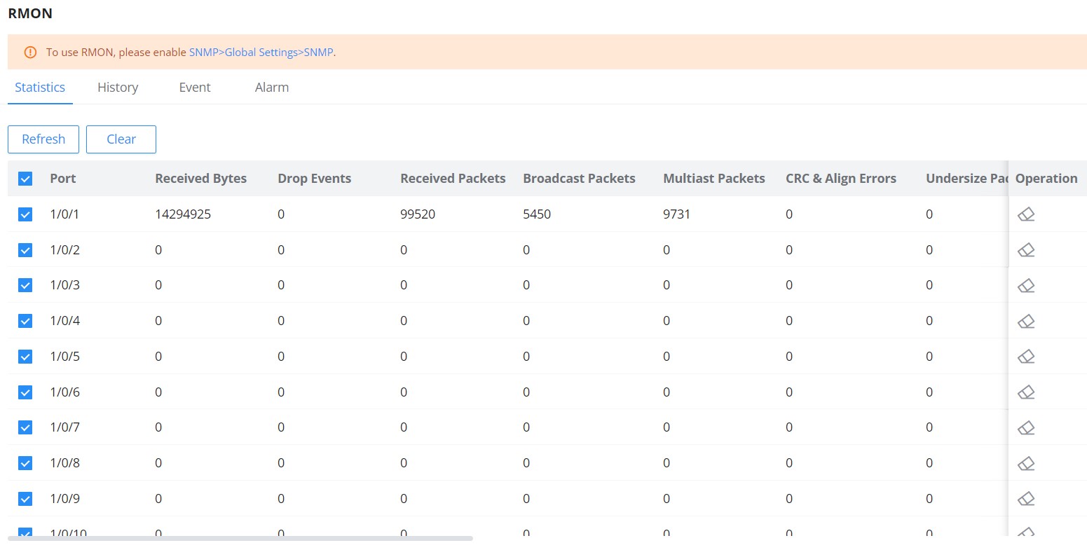
RMON History
The system will periodically collect statistics on various traffic information, including bandwidth utilization, number of error packets, and total number of packets based on the History ID.
Click Add to create a History ID and select the port. Set Maximum Samples from 1 to 50 and use Sampling Interval (s) to define how often samples are collected, from 1 to 3600 seconds. Owner is an optional identifier of up to 32 characters for the person or management process responsible for the history entry.
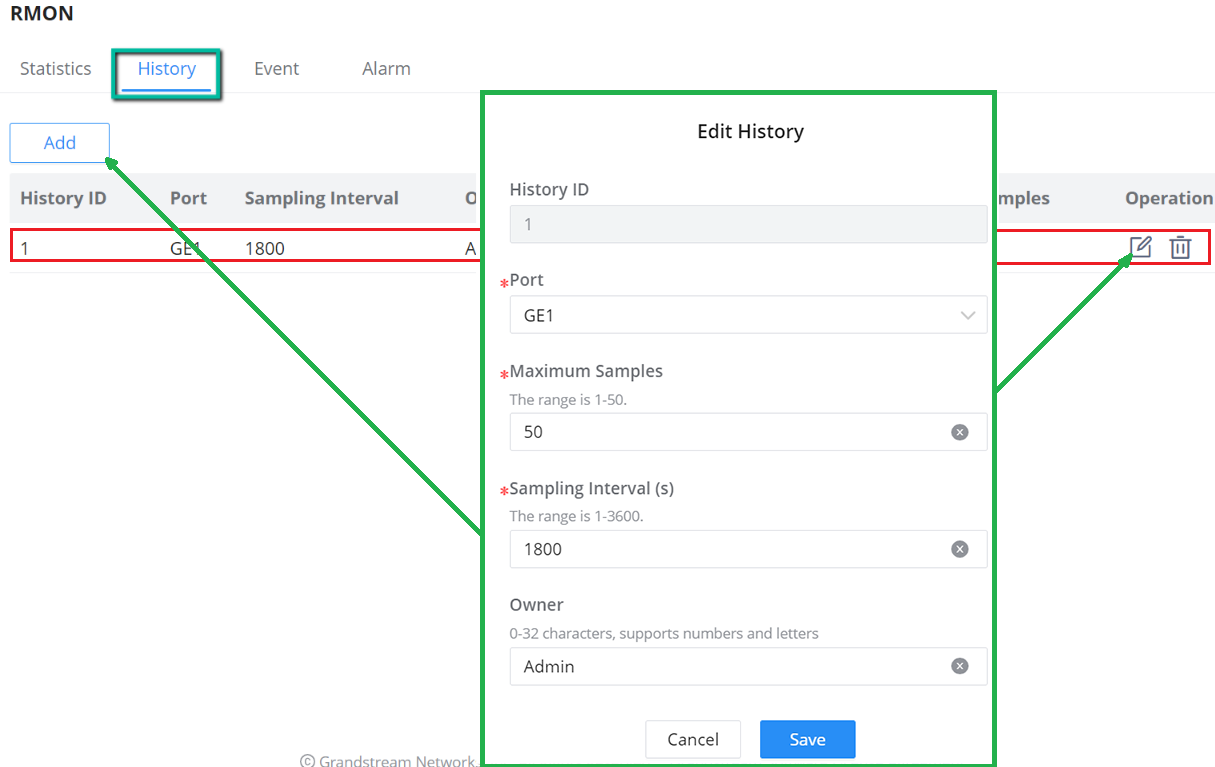
RMON Event
The event group controls the events and prompts from the device and provides all events generated by the RMON Agent. Click Add to create an Event ID, select whether the event records a log, sends an SNMP trap, or performs both actions, and enter the required community information. Owner is an optional identifier for the person or management process responsible for the event entry.
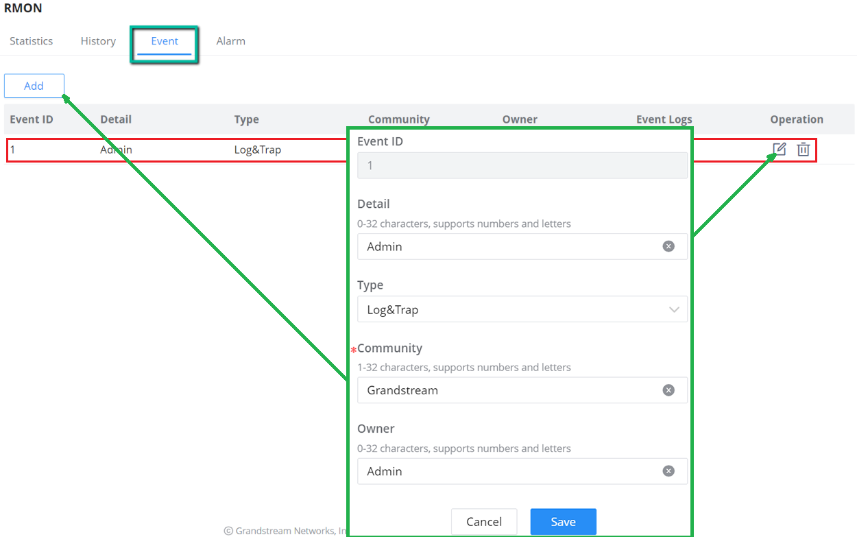
RMON Alarm
The system monitors the specified alarm variable. After pre-defining a set of thresholds and sampling time for the specified alarm, the system will obtain the value of the specified alarm variable according to the defined time period. When the value of the alarm variable is greater than or equal to the upper threshold, an upper alarm event will be triggered. When the value of the alarm variable is less than or equal to the lower threshold, a lower alarm event is triggered.
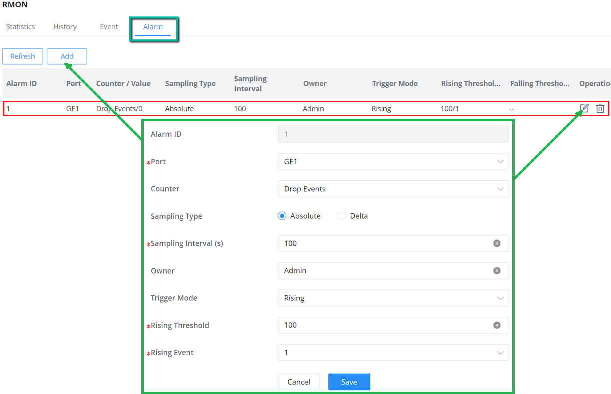
LLDP/LLDP MED
LLDP/LLDP MED is a one-way protocol, there are no request/response sequences. Information is
advertised by stations implementing the transmit function, and is received and processed by
stations implementing the receive function.
LLDP MED is an enhancement to LLDP that provides additional functionality to support media devices. LLDP MED features include: enabling network policy advertisement and discovery for real-time applications (such as voice and/or video);
LLDP Global Settings
This page allows a user to set general settings for LLDP including enabling LLDP and other parameters.
The global timers are TLV Advertise Interval (s) (5 to 32767), TTL Multiplier (2 to 10), Port Reinitializing Delay Time (s) (1 to 10), and LLDPDU Transmit Delay Time (s) (1 to 8191).
The global timers are TLV Advertise Interval (s) (5 to 32767), TTL Multiplier (2 to 10), Port Reinitializing Delay Time (s) (1 to 10), and LLDPDU Transmit Delay Time (s) (1 to 8191).
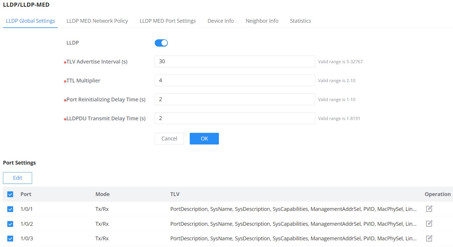
More configurations can adjusted per port (GE1 to GE10).
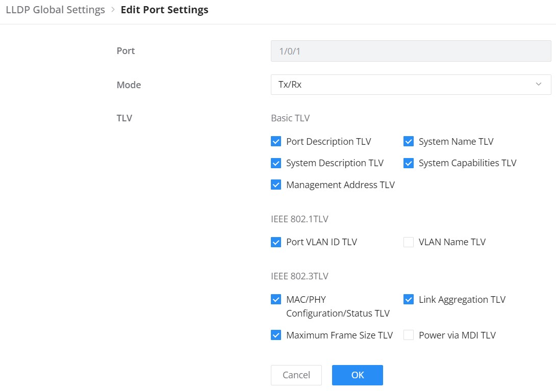
LLDP MED Network Policy
This page allows the network administrator to set the MED (Media Endpoint Discovery) network
policy. Click on the “Add” button to add a Network Policy or toggle ON Auto Voice Network Policy (Voice VLAN has to be configured as well).
Fast Report Count controls the number of fast LLDP-MED reports sent when a new endpoint is detected. The valid range is 1 to 10.
Fast Report Count controls the number of fast LLDP-MED reports sent when a new endpoint is detected. The valid range is 1 to 10.

To add a Network Policy, click on the “Add” button or click on the “Edit” icon under the Operation column to edit.

LLDP MED Port Settings
The user can configure LLDP MED Settings for each port on this page.
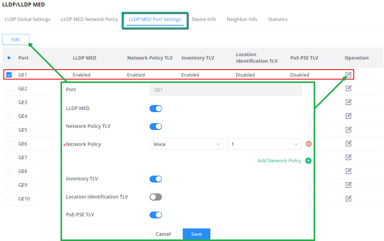
LLDP Device Info
This page displays information for LLDP Local Device connected to each port. Click on the port to view related LLDP information about that port, the information includes: Basic Info, IEEE 802.1 TLVs information, IEEE 802.3 TLVs (802.3 bt) information, MED Details, Network Policy…

Neighbor Info
This page lists the neighbors obtained on the switch ports. Click on the “Refresh” button to update the list.

LLDP Statistics
View the LLDP statistics of the local device through this feature. Click on “Refresh” to update the list.
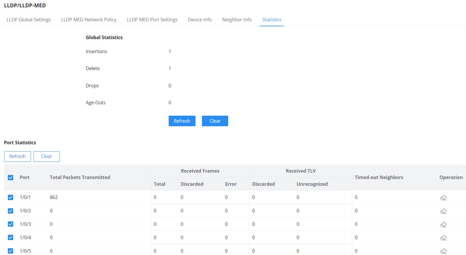
Energy Efficient Ethernet
EEE or Energy Efficient Ethernet helps on reducing the power consumption on interfaces like GWN780x switches Ethernet port, it achieves this by using power only during data transmission.
Navigate to Maintenance → Energy Saving Management, select a port to edit then enable 802.3 EEE.
- Configuration Status: shows if the configuration is enabled.
- Status: if a supported device is connected to the GWN780x switch, it will show if it’s enabled or not.

To enable EEE on a port, select a port then click on “Edit” button then toggle ON 802.3 EEE as shown below:
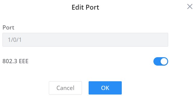
Alert
Open Maintenance → Alert to configure device and fiber-module alerts. Under Alert Settings, enable the required event, select its log level, and set the available alert and restore thresholds and waiting times. Events include CPU Usage, Memory Usage, PoE Power, MAC Address Exceeds Limit, Temperature, Fan Malfunction, PoE Chip Malfunction, and ARP Limit Exceeded. Available hardware events depend on the model.
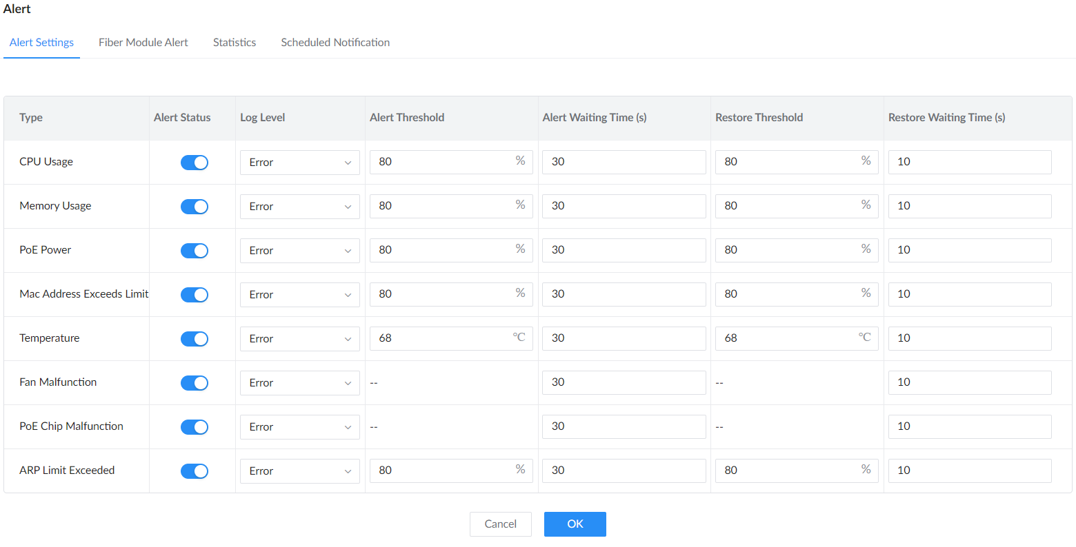
| Alert Status | Enable or disable the selected event. |
|---|---|
| Log Level | Choose the severity assigned to the event. |
| Alert Threshold / Alert Waiting Time (s) | Set the trigger threshold and how long the condition must persist before an alert is reported. Fields vary by event. |
| Restore Threshold / Restore Waiting Time (s) | Set the recovery threshold and waiting period used to report that the condition has cleared. |
Fiber Module Alert
Open Fiber Module Alert and edit the required optical port. Configure high and low temperature, voltage, transmit power, receive power, and bias-current alerts using the settings supported by the installed module.
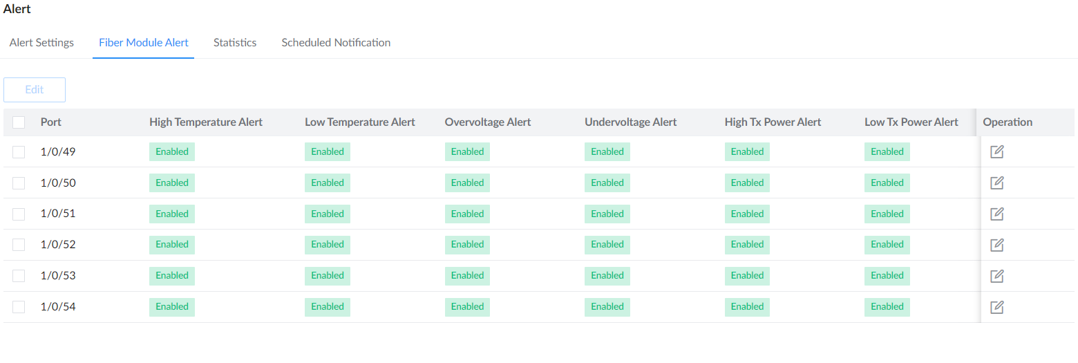
Scroll horizontally in the port list to view the remaining alert columns. Click the edit icon for the required port. The edit page includes high and low temperature, voltage, transmit (Tx) power, receive (Rx) power, and bias-current alerts; scroll down to reach the remaining rows and click OK after configuring the required settings.
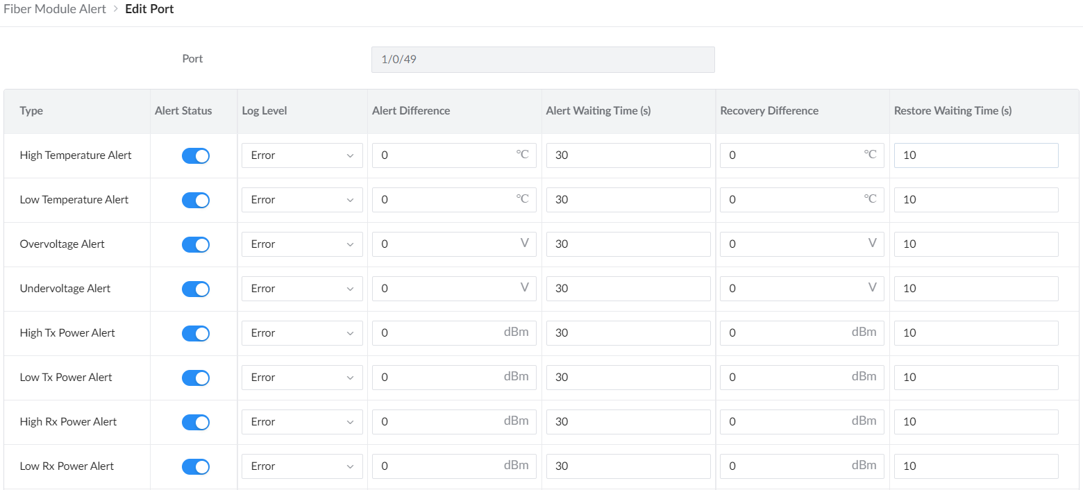
| Alert Status / Log Level | Enable each required alert and choose its severity. |
|---|---|
| Alert Difference / Recovery Difference | Set the differences used to trigger the alert and recognize recovery. Units follow the monitored value: temperature, voltage, optical power, or bias current. |
| Alert Waiting Time / Restore Waiting Time | Set how long the condition must persist before an alert or recovery is reported. |
Alert Statistics
The Statistics tab shows current status, last alert and restore times, values recorded at those events, and alert counts. Select the device or an optical port to inspect the corresponding events, including ARP-limit and fiber-module alerts.
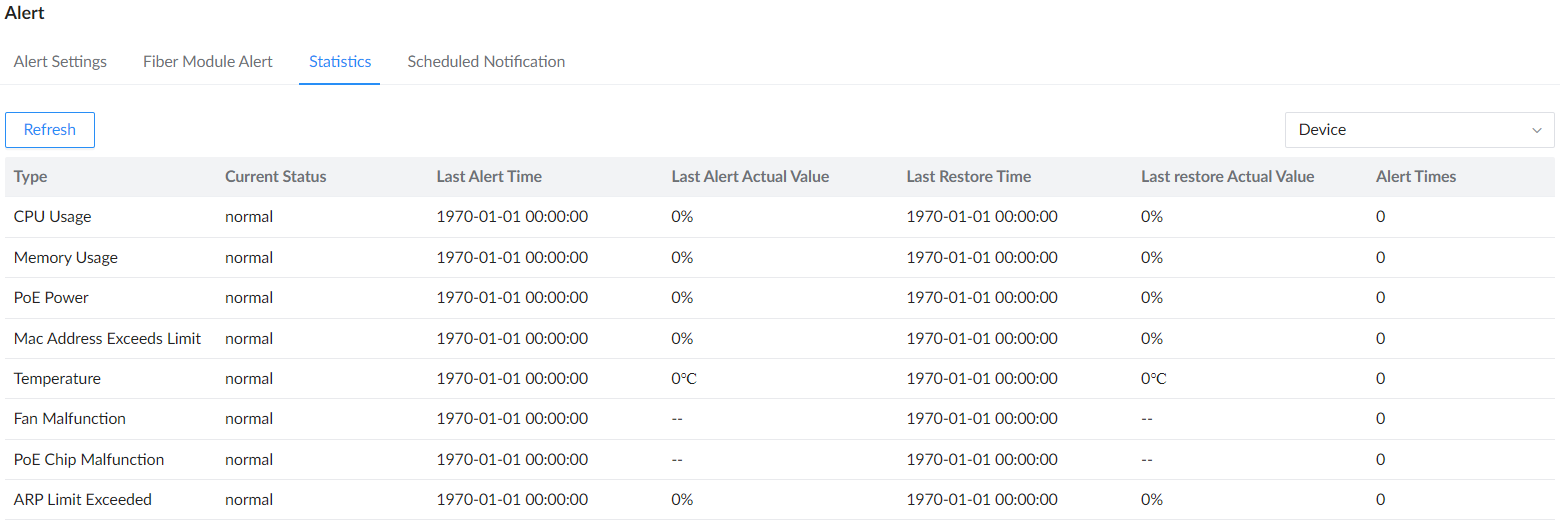
Scheduled Notification
Open Maintenance → Alert → Scheduled Notification. Enable Device Uptime and set the Report Interval (s) to control how often the device reports its uptime. Click OK to apply the settings.
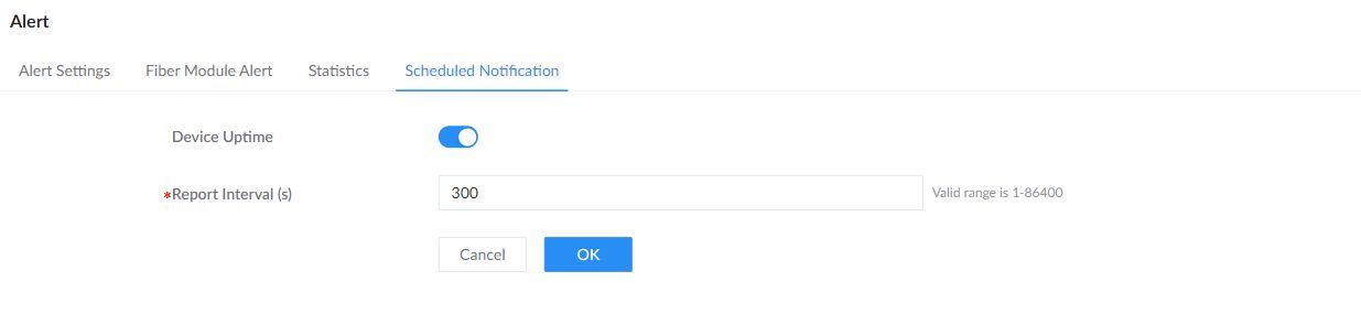
SYSTEM
Basic Settings
The basic settings page is split into three categories:
- Basic Info: first section, the user can specify a name for the GWN780x switch with a system location and contact.
- Time Settings: Configure time manually or through an NTP server. Use Daylight Saving Time (DST) Mode to disable DST or configure it by date or recurring schedule.
- Scheduled Reboot: the users can enable scheduled reboot by adding a schedule under the Time Policy.
Please navigate to the System → Basic Settings page.
Basic Info | |
Device Name | Specify a name for the device. |
System Location | Enter system location. |
System Contact | Specify the system contact. |
Time Settings | |
Date & Time | Select time synchronization method: Manual or Automatic (NTP Server).
Note: if the device is added to the GDMS Networking and Auto Sync Time feature (under Settings → System) is enabled then the local NTP setting on the device will be disabled. All managed devices will synchronize the time from GDMS Networking. |
System Time |
|
NTP Server | If Date & Time is set to Automatic (NTP Server), please specify the NTP Server address, by default is set to “pool.ntp.org” . |
Time Zone | Select the time zone from the drop-down list. |
DayLight Saving (DST) Mode |
|
Offset (Min) | Specify the Offset by minutes, range from 1 to 1440. |
Starting Time | Specify the starting date and time. |
Ending Time | Specify the ending date and time. |
Scheduled Reboot | |
Reboot Time | Select a reboot time from the drop-down list or click on “+” button to add a schedule. By default is disabled. |
Basic Settings
Access Control
In this section, the user can configure access to GWN780x switches.
Please navigate to System → Access Control.
Web Service Management
Open System → Access Control → Web Service Management to configure management-session and service settings. Confirm that any port or TLS changes remain compatible with your management tools before applying them.
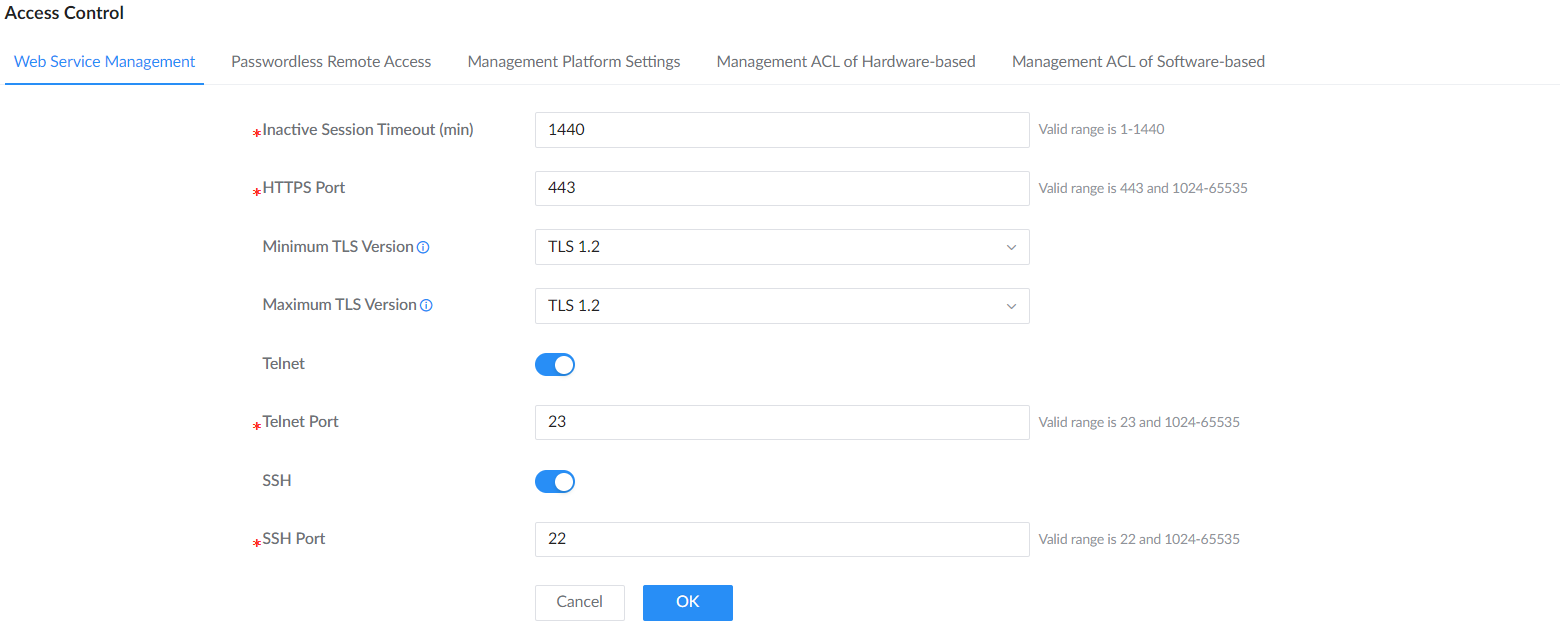
| Inactive Session Timeout (min) | Set how long an inactive management session remains open before automatic logout. |
|---|---|
| HTTPS Port | Set the port used to access the Web UI over HTTPS. The standard port is 443. |
| Minimum TLS Version / Maximum TLS Version | Select the allowed TLS version range for HTTPS connections. The minimum must not exceed the maximum. |
| Telnet / Telnet Port | Enable Telnet to display Telnet Port, then set the listening port to 23 or a value from 1024 to 65535. Use the same port in your Telnet client when connecting to the switch. Telnet does not encrypt the session; use SSH for encrypted command-line access. |
| SSH / SSH Port | Enable SSH and set its listening port. The standard port is 22. |
| Certificates | Use the default web certificate, or select Custom Certificate and import a custom certificate for HTTPS management. Confirm that the certificate is valid for the address administrators use to reach the switch. |
Passwordless Remote Access
Passwordless Remote Access lets GDMS Networking (or GWN Manager) open the switch Web UI remotely without prompting for the switch’s local username and password. It’s meant to simplify remote support and day-to-day management, especially in environments where access is handled through the management platform rather than by sharing device credentials.
To enable it on the switch, log in to the switch Web UI and go to System → Access Control. Open the Passwordless Remote Access tab, enable the option, then click OK to apply the change.
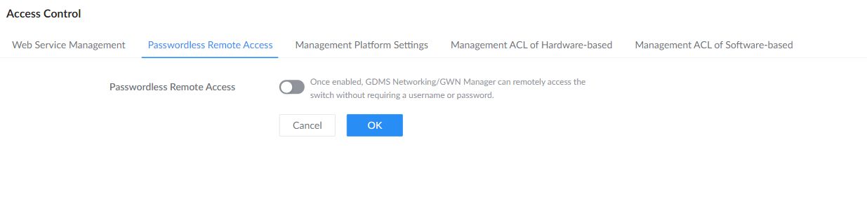
From GDMS Networking, open the Devices page, locate the target switch, and click the Remote Access icon in the Operation column to launch a proxied Web UI session.
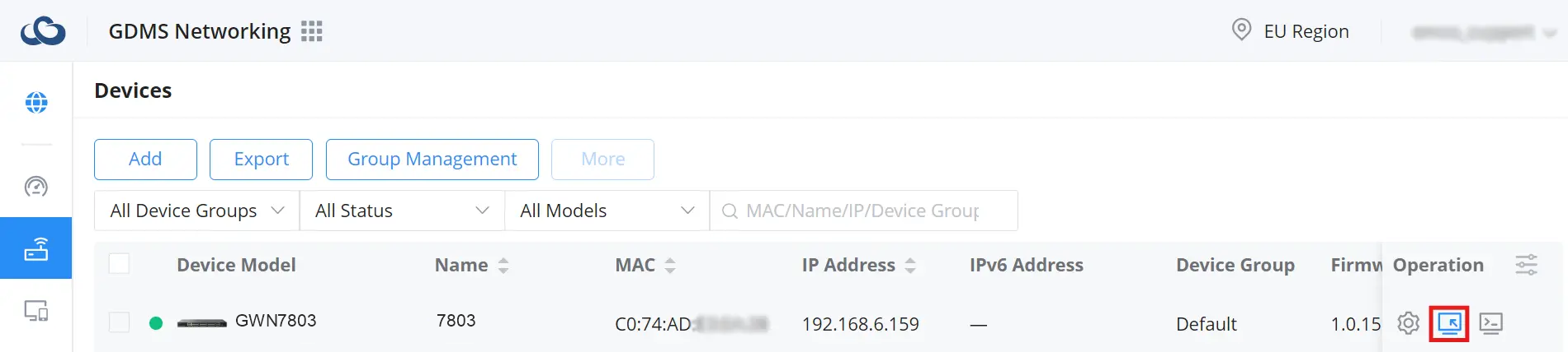
GDMS will begin establishing the remote access session and display a connection page while the proxy is being created.
Once the session is ready, the switch Web UI opens directly through GDMS without asking for the device password.
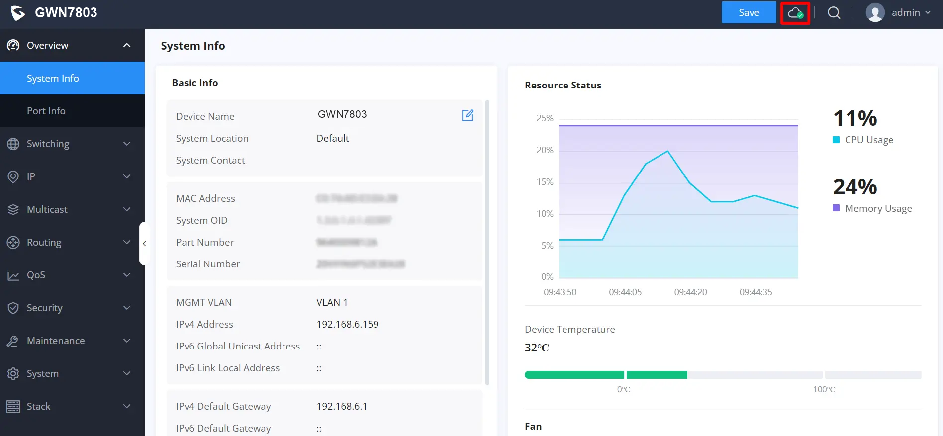
Warning: For security, only enable this feature for devices managed under trusted GDMS/GWN Manager accounts, and disable it when you don’t need passwordless access.
Management Platform Settings
The Management Platform Settings tab includes Management Server Settings. Enable it to configure Management Server Address and Management Server Port for GWN Manager or GWN Router. The port range is 1 to 65535. When Allow DHCP Option 43 to Override Management Server is enabled, the server address provided by DHCP Option 43 takes priority.
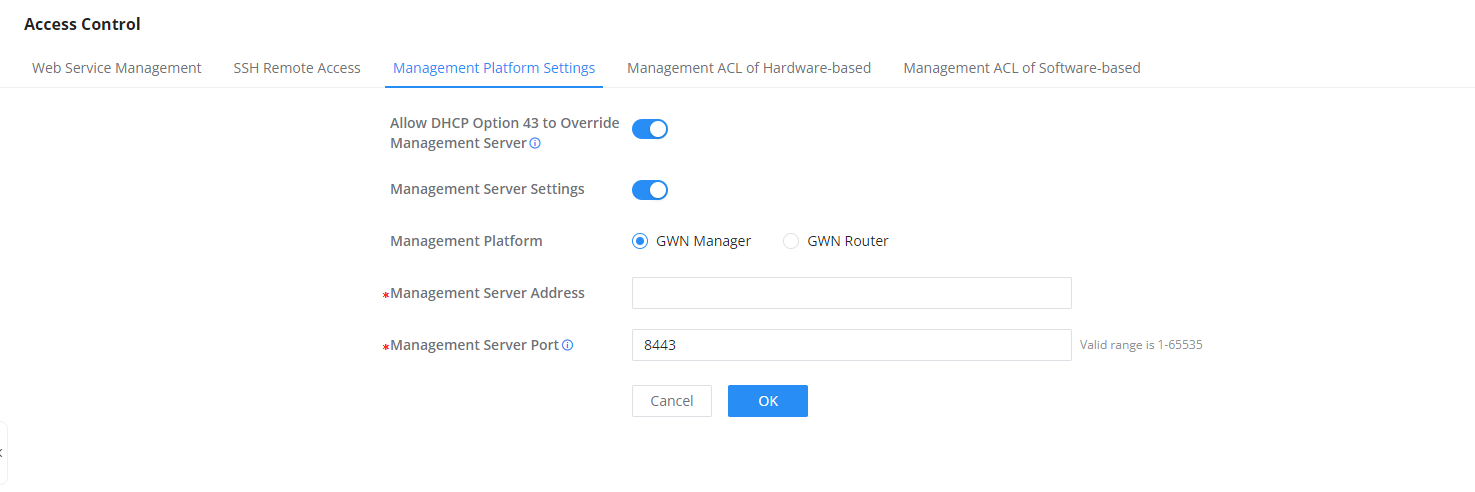
Management ACL of Hardware-based
On a GWN780x switch, the hardware management Access Control List (ACL) is designed to optimize resource efficiency by filtering traffic directly at the hardware level before it reaches the CPU. This pre-processing step ensures that only traffic matching the defined security rules is forwarded for further handling, effectively reducing unnecessary CPU load and enhancing overall performance. By offloading the initial traffic validation to the switch hardware, the GWN780x improves both network efficiency and security.
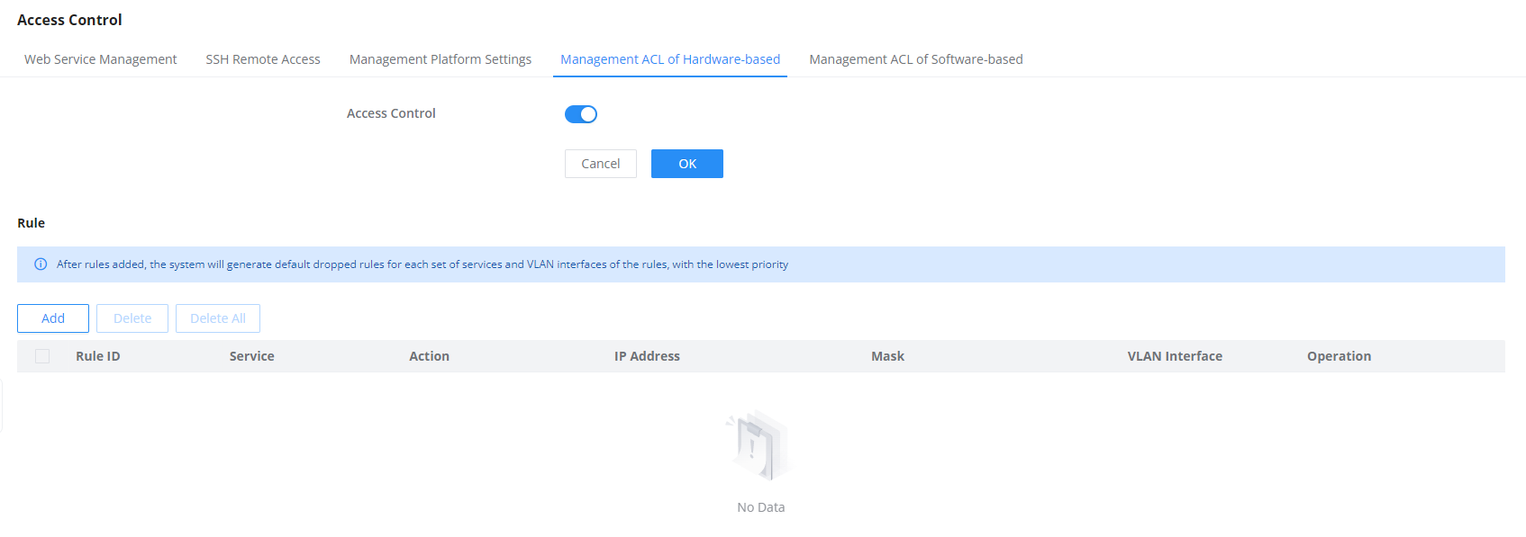
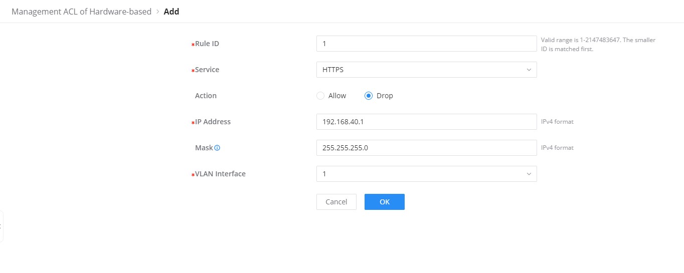
Management ACL of Software-based
On the GWN780x switch, the software-based Management ACL uses firewall-like rules to control who can access the network and its management features. This means it sets up restrictions to make sure that only authorized users and devices can access important parts of the switch, helping to keep the network secure and well-managed.
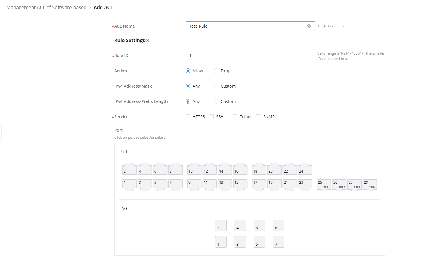
User Management
There are three levels of users, namely administrator, operator and monitor. The administrator authenticates and authorizes users who log in to the switch according to management need where each user has different permissions and passwords.
When adding a user, enter the password again in Confirm Password before saving the account.
When adding a user, enter the password again in Confirm Password before saving the account.
- Administrator
- Each device has one and only one administrator.
- The highest privileges can execute any command.
- The username admin cannot be changed, only the password can be changed.
- Support adding, and deleting operator and monitor.
- Operator
- Added by an administrator, there can be multiple accounts as Operators.
- The second highest authority can execute all commands except the administrator’s key operations and important mandatory commands
- Can’t change the username, only the password.
- Support adding, and deleting Monitor users.
- Monitor
- Multiple Monitors are possible with the permission of an Administrator or Operator.
- The lowest authority can only view switch status and statistics without any execution and configuration authority.
- Can’t change the username, only the password.
Click on the “Add” button to add a new user then specify the password and the user level (Operator or Monitor).

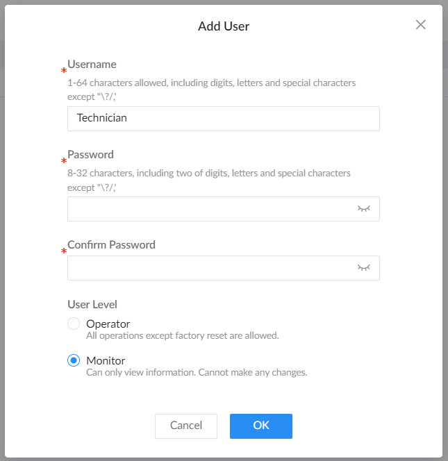
SSH Public Key
SSH public-key authentication lets a user sign in to the switch with an SSH key pair. Add the public key to the user account on the switch; keep the corresponding private key on the SSH client and never paste it into this form.
Open System → User Management. In the required user’s Operation column, click the key-shaped icon and choose Add SSH Public Key.
Confirm the displayed Username, paste the public key into SSH Public Key, and click OK to apply it. When connecting over SSH, use that username and configure the client to use the matching private key. SSH access must be enabled under Web Service Management.
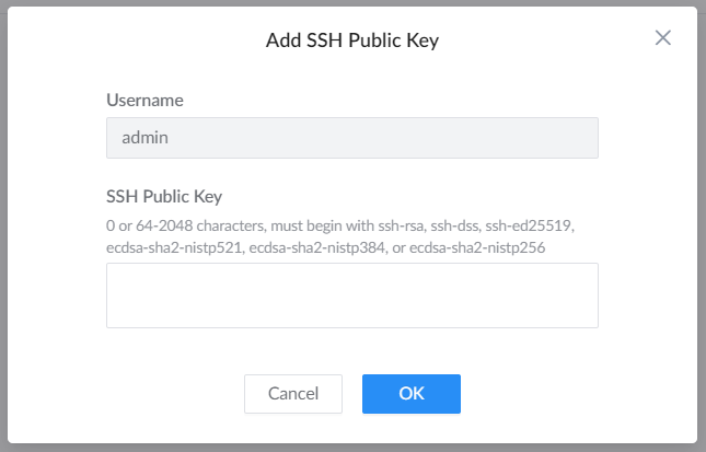
A nonempty key must contain 64 to 2048 characters and begin with one of the formats accepted by the dialog: ssh-rsa, ssh-dss, ssh-ed25519, ecdsa-sha2-nistp521, ecdsa-sha2-nistp384, or ecdsa-sha2-nistp256. Paste the public-key text, not a filename or private-key file.
Time Policy
The time policy page helps to create schedules, for example, Office working hours, Upgrade schedules or Reboot schedules.
To create a schedule, Please navigate to Web UI → System → Time Policy page, then click on “Create Policy” button, there are weekly schedules or absolute Date/Time schedules, for weekly schedules please select from the table the hours and days and as for absolute Date/Time select the days from the drop-down calendars and times from the drop-down menu. Please refer to the figure below.
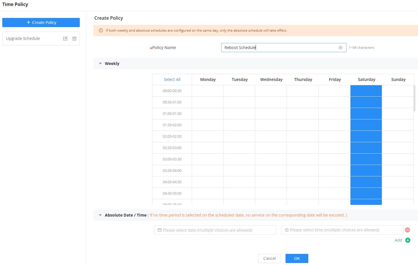
1588v2 TC
IEEE 1588v2 is a protocol for synchronizing clocks, enabling accurate time between nodes in a network.
A transparent clock or TC is a type of clock used in IEEE 1588v2 networks and it uses a Precision Time Protocol (PTP) messages to accurately calculate the time.
E2E or (End-to-End) transparent clock measures the delay at each network element between the master and slave clocks.
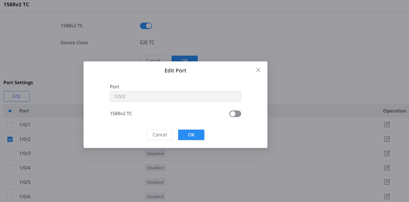
STACK
Stacking allows multiple supported switches to operate as a single logical unit, simplifying network management, increasing redundancy, and expanding port density.
To access this feature, navigate to:
Web UI → Stack → Stack Settings
💡 For full configuration examples, topology use cases, and best practices, please refer to the GWN78xx Stacking Feature Guide.
Stack Settings
Open Stack → Stack Settings to view member device IDs, priorities, next-boot values, and assigned stack ports. Click the edit icon in the required member’s Operation column to change its settings.
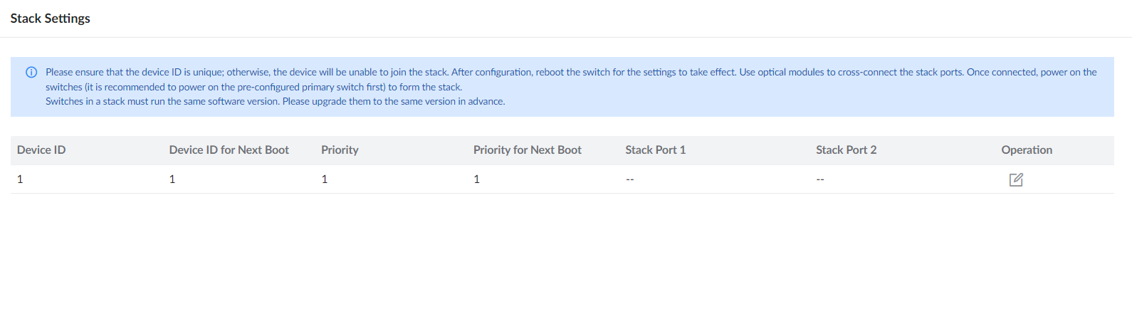
Edit the required member under Stack → Stack Settings to configure its next-boot device ID, priority, and stack ports. Each member must have a unique device ID, and all members must run the same firmware version. These settings take effect after reboot. Follow the stacking guide when connecting the stack ports and bringing the members online.
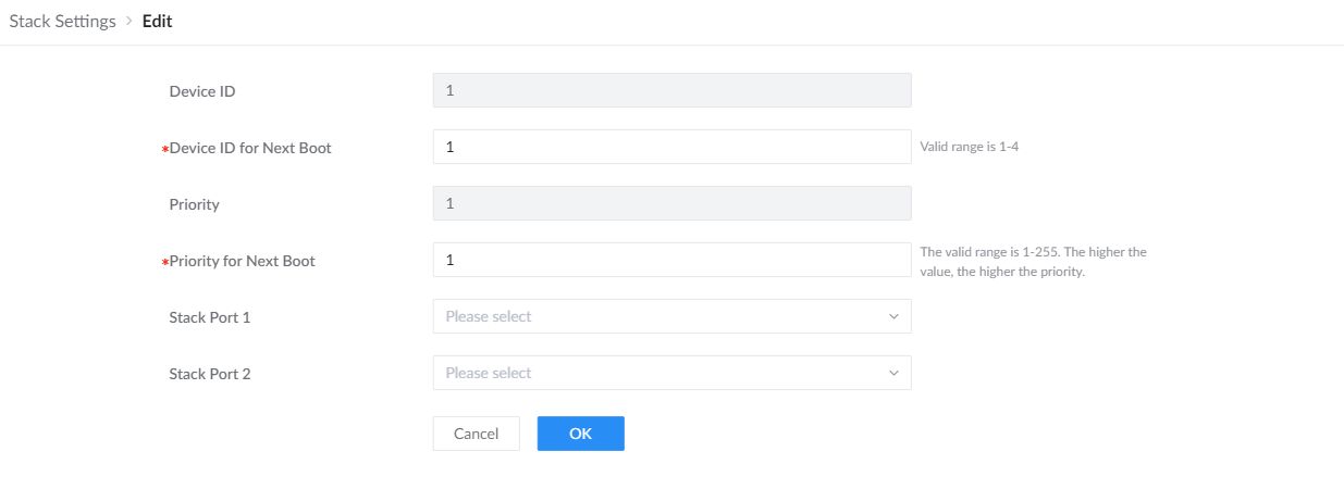
| Device ID for Next Boot | Assign a unique member ID for the next boot. Duplicate IDs prevent a device from joining the stack. |
|---|---|
| Priority for Next Boot | Set the priority used for the next boot. Higher values have higher priority. |
| Stack Port 1 / Stack Port 2 | Select the physical ports used for stack interconnection. Connect the selected optical ports according to the planned stack topology. |
Stack Info
This page displays the current stack topology and status, including member switches and their roles (Master/Member), device IDs, priorities, and port mappings.
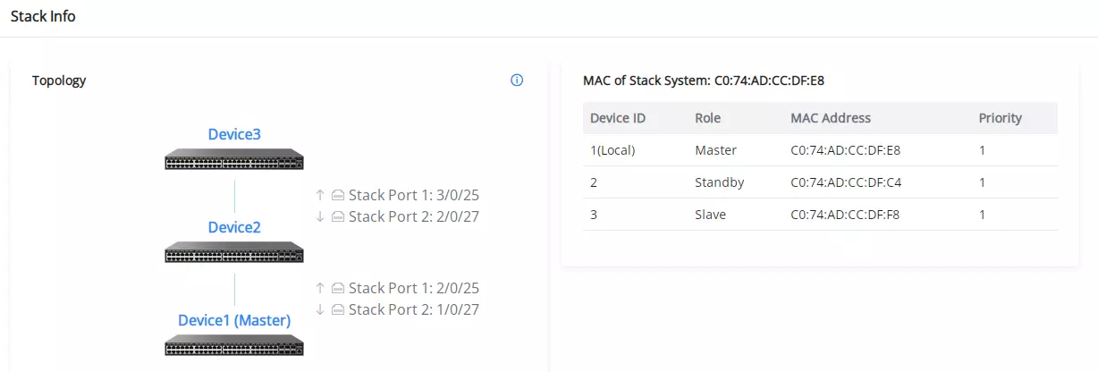
- If no data appears, ensure stack settings are properly configured and devices are connected.
- All stacked switches must be running the same firmware version.
CHANGE LOG
This section documents significant changes from previous versions of the GWN780x switches user manuals. Only major new features or major document updates are listed here. Minor updates for corrections or editing are not documented here.
Version 1.0.17.12
Product Name: GWN7801 / GWN7801P / GWN7802 / GWN7802P / GWN7803 / GWN7803P
- Added support for multiple RADIUS servers. [RADIUS]
- Added RADIUS authorization and accounting support in AAA. [AAA]
- Added support for multiple TACACS+ servers. [TACACS+]
- Added TACACS+ authorization and accounting support in AAA. [AAA]
- Replaced SSH Remote Access with Remote Support. [Remote Support]
- Added minimum and maximum HTTPS TLS version settings. [Web Service Management]
- Added more Grandstream OUIs for Voice VLAN. [OUI]
- Added MAC address hashing-algorithm selection. [MAC Address Table]
- Optimized DHCP server address-pool settings. [DHCP Server]
- Optimized ARP and NDP. [ARP Table]
- Added support for configuring the maximum number of static routes. [Static Routes]
- Added MLD Matching Domain under MLD Snooping. [MLD Matching Domain under MLD Snooping]
- Optimized port isolation with directional isolation groups. [Port Isolation]
- Optimized ACL advanced statistics settings. [ACL Statistics]
- Added ACL rule-utilization display in the CLI. [CLI Access]
- Added DAI drop behavior for nonzero rate limits and dropped-packet counters. [DAI]
- Added import/export and descriptive names for local MAC-based users. [Local MAC-Based Users]
- Added ND Snooping. [ND Snooping]
- Added scheduled backups. [Scheduled Backup]
- Added support for restoring a selected configuration file every time the switch reboots. [Restore Configuration on Reboot]
- Optimized management-platform connection diagnostics. [Management Platform Connection Diagnostics]
- Optimized SNMP. [SNMP]
- Added ARP-limit and fiber-module alerts. [Alert]
- Added Telnet port configuration. [Web Service Management]
- Added SSH public-key support for users. [SSH Public Key]
- Added passwordless remote access through GDMS Networking and GWN Manager. [Passwordless Remote Access]
- Increased the GWN7801P PoE power budget from 120 W to 130 W. [PoE]
Version 1.0.17.11
Product Name: GWN7806 / GWN7806P
- Added support for multiple RADIUS servers. [RADIUS]
- Added RADIUS authorization and accounting support in AAA. [AAA]
- Added support for multiple TACACS+ servers. [TACACS+]
- Added TACACS+ authorization and accounting support in AAA. [AAA]
- Replaced SSH Remote Access with Remote Support under Diagnostics. [Remote Support]
- Added minimum and maximum HTTPS TLS version settings. [Web Service Management]
Version 1.0.17.6
Product Name: GWN7806 / GWN7806P
- Increased the maximum supported multicast entries to 512. [IGMP Snooping Multicast Port]
Version 1.0.17.5
Product Name: GWN7806 / GWN7806P
- Added support for 2.5Gbps SFP+ modules. [SFP+ Speed Mode]
- Added queue packet-loss statistics. [Port Statistics]
- Added more Grandstream OUIs for Voice VLAN. [OUI]
- Added MAC address hashing-algorithm selection. [MAC Address Table]
- Added MAC address migration records. [MAC Address Migration Record]
- Added CoS for the management IP interface. [Management IP Interface]
- Optimized DHCP server address-pool settings. [DHCP Server]
- Optimized ARP and NDP. [ARP Table]
- Added policy routing. [Policy Route]
- Added support for configuring the maximum number of static routes. [Static Routes]
- Added MLD Matching Domain under MLD Snooping. [MLD Matching Domain under MLD Snooping]
- Optimized port isolation with directional isolation groups. [Port Isolation]
- Added DAI drop behavior for nonzero rate limits and dropped-packet counters. [DAI]
- Added import/export and descriptive names for local MAC-based users. [Local MAC-Based Users]
- Added ND Snooping. [ND Snooping]
- Added scheduled backups. [Scheduled Backup]
- Added support for restoring a selected configuration file every time the switch reboots. [Restore Configuration on Reboot]
- Optimized management-platform connection diagnostics. [Management Platform Connection Diagnostics]
- Optimized SNMP. [SNMP]
- Added ARP-limit and fiber-module alerts. [Alert]
- Added Telnet port configuration. [Web Service Management]
- Added SSH public-key support for users. [SSH Public Key]
- Added stack settings for individual members. [Stack Settings]
- Added passwordless remote access through GDMS Networking and GWN Manager. [Passwordless Remote Access]
- Optimized ACL advanced statistics settings. [ACL Statistics]
- Added ACL rule-utilization display in the CLI. [CLI Access]
- Added CLI pipe filtering. [CLI Access]
- Expanded stack support to include multicast, SNMP, RMON, identity authentication management, and ACL features. [Stack]
- Increased the maximum allowed MAC-address limit. [Port Security]
Version 1.0.15.138
Product Name: GWN7801(P) / GWN7802(P) / GWN7803(P).
- No major changes.
Version 1.0.15.137
Product Name: GWN7801(P) / GWN7802(P) / GWN7803(P), GWN7806(P).
- Added Passwordless Remote Access option that allows GDMS Networking / GWN Manager to open the device Web UI remotely without requiring the device username or password. [Passwordless Remote Access]
Version 1.0.15.135
Product Name: GWN7801(P) / GWN7802(P) / GWN7803(P), GWN7806(P).
- No major changes
Version 1.0.15.132
Product Name: GWN7801(P) / GWN7802(P) / GWN7803(P), GWN7806(P).
- Added support for ignoring credentials during SSH authentication. [SSH] [CLI Access]
- Added key for “encrypted” field to configuration files for Radius and TACACS+. [RADIUS] [TACACS+] [CLI Access]
Version 1.0.15.126
Product Name: GWN7801(P) / GWN7802(P) / GWN7803(P), GWN7806(P).
- Added support for switch stacking feature. [Stack]
- Added the Ability to disable the native VLAN. [VLAN Port Setting]
- Added support for PVLAN. [PVLAN]
- Added the option to set the Web GUI language on the configuration. [Web GUI Languages]
- Added support to use encrypted strings in password fields in CLI. [RADIUS]
- Added support for “Calling-Station-Id” in RADIUS Access-Request. [Identity Authentication Management]
Version 1.0.13.18
Product Name: GWN7801(P) / GWN7802(P) / GWN7803(P), GWN7806(P).
- No major changes
Version 1.0.13.6
Product Name: GWN7801(P) / GWN7802(P) / GWN7803(P), GWN7806(P).
- Added LED status change during the start-up process. [LED Indicators]
- Removed PTP settings from Web UI.
Version 1.0.9.15
Product Name: GWN7806(P)
- Added port groups. [Port Group]
- Added LLDP auto-config for Auto Voice VLAN mode in Voice VLAN. [LLDP/LLDP MED Auto Config]
- Added more features for STP, including ignore VLAN in BPDU, root protection and loopback protection. [Ignore VLAN in BPDU] [Root Protection] [Loop Protection]
- Added more OUI in Voice VLAN. [OUI]
- Added IP configuration for MGMT VLAN. [MGMT VLAN]
- Added redirect to interface for ACL. [Redirect to Interface]
- Added VLAN binding to ACL function.[VLAN Binding to ACL]
- Optimized the rate limit groups from 32 to128 in ACL. [Rate Limit Settings]
- Added mask for IPSG/IPv6SG. [IP Source Guard]
- Added remote-ID configuration based on port for DHCP Snooping. [DHCP Option 82]
- Changed DHCP’s Option 82 Circuit ID/Remote ID. [DHCP Option 82]
- Added entries fixed for DHCP/DHCPv6 Snooping. [DHCP Snooping]
- Added flow upgrade via manual upgrade. [Upgrade Flow]
- Added more settings for logs, including minimum log level and log aggregation. [Log Aggregation]
- Added Ping watchdog in diagnostics. [Ping Watchdog]
- Added connection diagnostics of GWN router. [GWN Router]
- Added RSPAN, including port-based and ACL-based remotely mirroring. [RSPAN] [Configuring an ACL based RSPAN]
- Added new SNMP Traps. [Trap Event]
- Added 802.3bt info in LLDP. [IEEE 802.3 TLV]
- Added Maintenance Alerts. [Alert]
- Added management ACL, including hardware-based and software-based management ACL. [Management ACL of Hardware-based] [Management ACL of Software-based]
- Added Layer 3 discovery and management by GWN router.[Management Platform Settings]
- Added ACL for VTY (SSH and telnet). [Web Service Management]
- Added additional Radius Access-Request Attributes. [Identity Authentication Management]
- Removed Commited Burst Configuration from Queue Shaping. [Queue Shaping]
- Added 1588v2 P2P TC. [1588v2 P2P TC]
- Added NAS-Port-Type value 15 with alternate management VLAN. [MGMT VLAN]
- Added ability to shutdown port by profile group. [Port Group]
- Added more port details such as neighbor and PoE power history info. [Port Info]
- Added more port statistics info. [Port Statistics]
- Added loopback detection. [Loopback Detection]
- Added support for QinQ. [QinQ]
- Added MAC-based VLAN. [MAC VLAN]
- Added protocol-based VLAN. [Protocol VLAN]
- Added VLAN translation. [VLAN translation]
- Added untagged OUI mode for voice VLAN. [Voice VLAN]
- Added gateway priority when using DHCP to get VLAN IP address [VLAN IP Interface]
- Added import/export IPSG binding table for IP Source Guard. [IP Source Guard]
- Added IPv6 Source Guard. [IPv6 Source Guard]
- Added MAC bypass authentication. [Identity Authentication Management]
- Added upgrade by FTP and Explicit FTPS. [FTP] [Explicit FTPS]
- Added DST mode for time settings. [DST]
- Added HTTPS/SSH port customization. [Web Service Management]
- Added GWN Manager takeover function. [Management Platform Settings]
- Added support to see switch clients and other information. [Port Info]
- Optimized DHCP option 43 settings for DHCP server. [DHCP Server]
- Optimized routing table. [Routing Forwarding]
- Added port scheduled enabling feature. [Scheduled enabled]
- Added DHCPv6 Snooping. [DHCPv6 Snooping]
- Optimized CPU and memory usage in Web GUI. [System Info]
- Optimized search for Web GUI. [Search]
Version 1.0.1.14
Product Name: GWN7806(P)
- This is the initial release.
Firmware Version 1.0.9.15
Product Name: GWN7801(P)/GWN7802(P)/GWN7803(P)
- Added port groups. [Port Group]
- Added LLDP auto-config for Auto Voice VLAN mode. [LLDP/LLDP MED Auto Config]
- Added more features for STP, including ignore VLAN in BPDU, root protection and loopback protection. [Ignore VLAN in BPDU] [Root Protection] [Loop Protection]
- Added more OUI in Voice VLAN. [OUI]
- Added IP configuration for MGMT VLAN. [MGMT VLAN]
- Added redirect to interface for ACL. [Redirect to Interface]
- Added VLAN binding to ACL function.[VLAN Binding to ACL]
- Optimized the rate limit groups from 32 to128 in ACL. [Rate Limit Settings]
- Added mask for IPSG/IPv6SG. [IP Source Guard]
- Added remote-ID configuration based on port for DHCP Snooping. [DHCP Option 82]
- Changed DHCP’s Option 82 Circuit ID/Remote ID. [DHCP Option 82]
- Added entries fixed for DHCP/DHCPv6 Snooping. [DHCP Snooping]
- Added flow upgrade via manual upgrade. [Upgrade Flow]
- Added more settings for logs, including minimum log level and log aggregation. [Log Aggregation]
- Added Ping watchdog in diagnostics. [Ping Watchdog]
- Added connection diagnostics of GWN router. [GWN Router]
- Added RSPAN, including port-based and ACL-based remotely mirroring. [RSPAN] [Configuring an ACL based RSPAN]
- Added new SNMP Traps. [Trap Event]
- Added 802.3bt info in LLDP. [IEEE 802.3 TLV]
- Added Maintenance Alerts. [Alert]
- Added management ACL, including hardware-based and software-based management ACL. [Management ACL of Hardware-based] [Management ACL of Software-based]
- Added Layer 3 discovery and management by GWN router.[Management Platform Settings]
- Added ACL for VTY (SSH and telnet). [Web Service Management]
- Added additional Radius Access-Request Attributes. [Identity Authentication Management]
- Removed Commited Burst Configuration from Queue Shaping. [Queue Shaping]
Firmware Version 1.0.5.61
Product Name: GWN7801(P)/GWN7802(P)/GWN7803(P)
- Optimized search for Web GUI. [Search]
- Optimized CPU and memory usage in Web GUI. [System Info]
- Optimized device IP address display [System Info]
- Added more port details such as neighbor, PoE power history info. [Port Info]
- Added port scheduled enabling feature. [Port Basic Settings]
- Added more port statistics info. [Port Statistics]
- Added loopback detection feature. [Loopback Detection]
- Added QinQ. [VLAN]
- Optimized trunk port settings. [VLAN Port Members]
- Added MAC-based VLAN. [MAC VLAN]
- Added protocol-based VLAN. [Protocol VLAN]
- Added VLAN translation. [VLAN Port Settings]
- Added default gateway configuration under MGMT VLAN. [VLAN IP Interface]
- Added gateway priority when using DHCP to get VLAN IP address. [VLAN IP Interface]
- Optimized DHCP option 43 configuration for DHCP server. [DHCP Server]
- Added advanced ACL settings, including mirroring, statistics, and priority remapping for a rule. [ACL]
- Added import/export IPSG binding table for IP Source Guard. [IP Source Guard]
- Added IPv6 Source Guard. [IPv6 Source Guard]
- Optimized remote ID and Circuit ID for DHCP Snooping. [DHCP Snooping option 82]
- Added DHCPv6 Snooping. [DHCPv6 Snooping]
- Added upgrade by FTP and Explicit FTPS. [Upgrade]
- Added connection diagnostics with GWN.Cloud/Manager. [Cloud/Manager Connection Diagnostics]
- Optimized EEE. [Energy Efficient Ethernet]
- Added DST mode for time settings. [Basic Settings]
- Added HTTPS/SSH port customization. [Web Service Management]
- Optimized Manager settings. [Manager Settings]
- Added rate limit by ACL binding to VLAN. [VLAN Binding to ACL]
- Added MAC bypass authentication. [Local User of MAC-based]
- Add GWN Manager takeover function. [Manager Settings]
- Expanded DHCP leases range up to 11520 min. [DHCP Server]
- Adjust the maximum length of the command line to 2000. [CLI Access]
- Added support to see switch clients and other information. [Port Info]
Firmware Version 1.0.3.37
Product Name: GWN7801(P)/GWN7802(P)/GWN7803(P)
- Added support for GWN Cloud 1.1.25.23. [GWN.Cloud]
- Added support of SSH and TELNET in # mode. [Login Remotely using SSH]
- Added support of Dynamic Voice VLAN. [Voice VLAN]
- Added support of voice VLAN OUI Untagged mode. [Voice VLAN]
- Added support of backspace when using CLI. [Login Remotely using SSH]
Firmware Version 1.0.3.19
Product Name: GWN7801(P)/GWN7802(P)/GWN7803(P)
- Added support of EEE [Energy Efficient Ethernet]
- Added feature of ARP table [ARP table]
- Added support of neighbor discovery [Neighbor Discovery]
- Added feature of IPv6 RA, RS [Neighbor Discovery]
- Added feature of copper test [Copper test]
- Added feature of one key debugging [One-click Debugging]
- Added feature of VLAN IP Interface [VLAN IP Interface]
- Added feature of DHCP server [DHCP Server]
- Added feature of time scheduling [Time Policy]
- Added support of Layer 2 and Layer 3 GWN Manager discovery [Access Control]
- Added support of ErrDisable status to port information [Port Info]
- Added support of SSH/Telnet client [Access Control]
- Added support of fan status to system information [System Info]
- Added support of SSH remote access [SSH remote access]
- Added support of switch IP interface DNS configuration [DNS]
- Added support of port based enable/disable in QoS port priority [Port Priority]
- Added support of SP-WRR and SP-WFQ to queue policy of QoS [Queue Scheduling]
- Added feature of routing table [Routing Table].
- Added feature of static routing [Static Routes].
- Added feature of DHCP relay [DHCP Relay]
Firmware Version 1.0.1.36
Product Name: GWN7801(P)/GWN7802(P)/GWN7803(P)
- Added DNS configurations for switch IP service. [DNS]
Firmware Version 1.0.1.30
Product Name: GWN7801(P)/GWN7802(P)/GWN7803(P)
- No major changes
Firmware Version 1.0.1.20
Product Name: GWN7801(P)/GWN7802(P)/GWN7803(P)
- This is the initial version.