SoftwareUCM is a software IPPBX solution that allows deployment on bare-metal or a virtualized environment, either on-premise or on the cloud, to achieve a flexible telephony solution that meets the needs of a few users with limited telephony capacity, to a large telephony capacity. Using SoftwarUCM, the user can also benefit from the multi-tenancy of the hardware and the solution, which allows an efficient use of the hardware resources and separation of processes and data.
The following table summarizes all the technical specifications including the protocols/standards supported, voice codecs, telephony features, and languages for the SoftwareUCM.
Voice/Video Capabilities
Voice-over-Packet
Capabilities
LEC with NLP Packetized Voice Protocol Unit, 128ms-tail-length carrier grade Line Echo Cancellation, Dynamic Jitter Buffer, Modem detection & auto-switch to G.711, NetEQ, FEC 2.0, jitter resilience up to 50% audio packet loss
Mass provisioning using AES encrypted XML configuration file, auto-discovery & auto-provisioning of Grandstream IP endpoints via ZeroConfig (DHCP Option 66 multicast SIP SUBSCRIBE mDNS), eventlist between the local and remote trunk
Customizable language pack for voice prompt to support any other languages
Call Center
Multiple configurable call queues, automatic call distribution (ACD) based on agent skills/availability/workload, in-queue announcement
Customizable Auto Attendant
Up to 5 layers of IVR (Interactive Voice Response) in multiple languages
Telephony Operating System
Based on Asterisk version 16
Maximum Call Capacity
Up to 10,000 extension users
Up to 30,000 simultaneous SIP registrations
Up to 2,500 concurrent calls
Up to 50 call attempts per second (CAPS)
Call Features
Call park, call forward, call transfer, call waiting, caller ID, call record, call history, ringtone, IVR, music on hold, call routes, DID, DOD, DND, DISA, ring group, ring simultaneously, time schedule, PIN groups, call queue, pickup group, paging/intercom, voicemail, call wakeup, SCA, BLF, voicemail to email, fax to email, speed dial, call back, dial by name, emergency call, call follow me, blacklist/whitelist, voice conference, video conference, eventlist, feature codes, busy camp-on/ call completion, voice control, post-meeting reports, virtual fax sending/receiving.
Wave App
Free; Available for desktop (Windows 10+, Mac OS 10+), web (Firefox and Chrome Browsers) and mobile (Android & iOS), allows users to join UCM-hosted meetings, communicate with other users/solutions and make/receive calls using SIP accounts registered to the SoftwareUCM.
Firmware Upgrade
Supported by Grandstream Device Management System (GDMS), a zero-touch cloud provisioning and management system, It provides a centralized interface to provision, manage, monitor, and troubleshoot Grandstream products
SoftwareUCM is designed to run in a Linux environment using the AlmaLinux distribution. It can be installed on either physical or virtual machines, offering flexibility based on the user’s requirements.
For instructions on installing SoftwareUCM on a physical machine, please refer to the guide linked below.
SoftwareUCM also supports installation on various hypervisors. For detailed installation instructions, please refer to the corresponding guides listed in the table below:
When deploying, cloning, or restoring SoftwareUCM systems, ensure that disk or partition UUIDs are not duplicated between instances. Duplicate UUIDs may cause the Logical Volume Manager (LVM) to incorrectly identify storage volumes during startup, which can result in disk mounting failures and system malfunction.
Managing SoftwareUCM
Once SoftwareUCM is successfully installed, users can start utilizing its features and functionalities by accessing the console menu, which offers an interface that allows users to navigate through different options and commands.
The console supports multi-disk management, allowing administrators to allocate SoftwareUCM instances across different disks and manage disk storage directly from the console. Administrators can also bind SoftwareUCM instances to specific CPU cores for resource allocation purposes.
For more information regarding managing softwareUCM through the console menu, please refer to the guide below:
To access SoftwareUCM, users need to retrieve the login information from the console by using the “List SoftwareUCMs” option.
List SoftwareUCM Information
Users can enter the IP address, and login to the SoftwareUCM instance using the initial username and password displayed in the console.
Note:
If the instance did not get assigned an IP address, “Admin Portal” will appear blank.
SoftwareUCM Login Page
Trial Period Activation
The steps below outline the process of applying for a trial period for the SoftwareUCM. The trial period is available for the base package, which offers 50 user extensions and a maximum of 24 concurrent calls.
Note
Applying for a trial period can only be done through online activation.
After the initial installation, the SoftwareUCM will prompt the administrator to Select SoftwareUCM Device Mode. Two options are available:
PBX Mode: A license must be activated. After activation, the device operates as a full PBX.
Media Server Mode: No license activation required. The device operates solely as a media server with no PBX functionality.
Note:
This mode selection cannot be changed without performing a factory reset. If Media Server Mode is selected, the device will skip license activation entirely and no trial period will be available. Please refer to the Cluster section for more information.
SoftwareUCM Device Mode Selection
To proceed with the trial, select PBX Mode and click Next.
Read the license agreement to understand all the terms and conditions of using SoftwareUCM. Then, agree to the terms and conditions of use to continue.
SoftwareUCM License Agreement
Click on “free trial” to access the trial application page.
SoftwareUCM Service Plan Activation
Fill the necessary information in the trial application form.
Trial Period Form
Access your email inbox and find the email which contains the license file. Once found, download the file from the attachment.
License Email
On the SoftwareUCM interface, click on “Upload” to add the license file.
Upload Trial License
On the file browser, select the location where the license file is stored then upload it to the SoftwareUCM.
File Explorer
When the license file is added, the following page will be displayed showing information regarding the SoftwareUCM, the activation date and the expiration date of the trial, in addition to the package information.
Trial Period Activated
Open Source License
As shown in the screenshot below, the open source license for SoftwareUCM is available at the bottom of the page.
SoftwareUCM Open Source License
SYSTEM STATUS
Dashboard
Storage Usage
Resource Usage
SoftwareUCM Service
PBX Status
Trunks
RemoteConnect
SoftwareUCM Dashboard
System Information
Under this section, the user can view information related to the system’s hardware and software. The page is organized into three tabs: General, Network, and Remark.
General
The General tab displays core system and version details. The table below describe th information displayed on this tab.
System Information General
Field
Description
System Information
Model
Displays the device model, this will show as SoftwareUCM.
Device MAC Address
The MAC address assigned to the SoftwareUCM instance.
Serial Number
The unique serial number of the SoftwareUCM instance.
System Time
The current system time, including the configured timezone offset.
Up Time
The elapsed time since the last system start or reboot.
Version Information
Wave Web
The version of the Wave Web currently installed.
Program
The version of the SoftwareUCM program currently running.
ISO
The version of the ISO image used to install SoftwareUCM on this machine.
Network
The Network tab displays the current network interface configuration. SoftwareUCM supports dual network interfaces (LAN 1 and LAN 2), each active interface is listed with its own set of parameters.
If only the active and configured network interface will be displayed on this tab.
System Information Network
Field
Description
MAC Address
The MAC address of this network interface.
IPv4 Address
The IPv4 address currently assigned to this interface.
IPv6 Address Link
The link-local IPv6 address assigned to this interface, if applicable.
Gateway
The default gateway configured for this interface.
Subnet Mask
The subnet mask for this interface’s network segment.
DNS Server
The DNS server(s) configured for name resolution. Multiple entries may be shown (e.g. 192.168.6.1, 8.8.8.8).
Remark
The Remark tab allows the administrator to enter comments or notes about this SoftwareUCM system.
System Information Remark
If a RemoteConnect plan has been purchased, remarks entered here will be synced to GDMS after saving. Remarks can also be modified directly from GDMS, and any changes made there will be synced back to SoftwareUCM.
SoftwareUCM GDMS Information
Note:
The remark can also be modified from the SoftwareUCM console by selecting Modify Remark. However, remarks set via the console are independent and are not synced to the web UI or to GDMS. For more details about console configuration, please refer to the SoftwareUCM Console User Guide.
Active Calls
The active calls on the SoftwareUCM are displayed in the Web GUI🡪SystemStatus🡪Active Calls page. Users can monitor the status, hang up a call, and barge in the active calls in a real-time manner.
Active Calls Status
To view the status of active calls, navigate to Web GUI🡪SystemStatus🡪Active Calls. The following figure shows extension 1004 is calling 1000. 1000 is ringing.
Active Calls Ringing Status
The following figure shows the call between 1000 and 5555 is established.
Active Call Established Status
The gray color of the active call means the connection of call time is less than half an hour. It means this call is normal.
Active Short length Call
The orange color of the active call means the connection of call time is greater than half an hour but less than one hour. It means this call is a bit long.
Active Medium length Call
The red color of the active call means the connection of call time is more than one hour. It means this call could be abnormal.
Active Long length Call
Setup Wizard
When you log in to the SoftwareUCM Web GUI interface for the first time, the system will automatically start the setup wizard and expand the description.
The setup wizard guides users to complete basic configuration, such as administrator password modification, Email Delivery settings, timezone settings, extension settings, trunks and routes configuration, etc. The setup wizard cannot be skipped and needs to be completed to access the configuration page of the SoftwareUCM.
The first step of the setup wizard is to configure the user settings, in this step, it’s mandatory to configure a new password for the super administrator, and to configure an email address.
The user can also enable file encryption per type of file.
Setup Wizard
On the second step, the user can configure the networking settings of the device. This includes the Maximum Transmission Unit (MTU) and the IP acquisition method.
Network Settings
In the third step, the user can configure the time zone, date format, time format, and prompt language.
TimePrompt Language
On the fourth step, the user can create a batch of extensions. The user can also configure a SIP password and a user/Wave password which can be initially used to register, or to log into the extension, respectively.
Extensions
On the fifth step, the user can configure and create initial trunk and route configuration.
TrunksRoutes
On the sixth step, the user can view a summary of all the configuration which has been set in the previous steps.
Summary
Network Status
In this page, the user can view information regarding the network status of the SoftwareUCM such as the network interfaces of the SoftwareUCM, the network traffic activity in each network interface.
Network Port Real-time Traffic
In Network Port Real-time Traffic page, the user can view the volume of the traffic exchanges in the SoftwareUCM. The volume of the traffic depends on the number of calls, the codecs used, and the services configured on the SoftwareUCM.
Network Port Real time Traffic
Active Connections
In Active Connections window, the user can view all the active connections, this incudes local and external connections. One or multiple open connections may correspond to one or multiple services.
Active Connections
Active Unix Domain Sockets
In this page, the user can view the active unix domain socket connections. These connections are related only to internal process communication.
Active Unix Domain Sockets
EXTENSION/TRUNK
Extensions
Create a New SIP Extension
To create a new SIP user manually, go to Web GUI > Extension/Trunk> Extensions. Click on “Add” and a new window will show for users to fill in the extension information.
Create New SIP Extension
Extension options are divided into the following categories:
Basic Settings
Media
Call Policy
Features
Voicemail
Custom Time
Wave Client
Follow me
Advanced Settings
The configuration parameters are as follows.
Field
Description
General
Extension
The extension number associated with the user.
CallerID Number
Configure the CallerID Number that would be applied for outbound calls from this user.
Note:
The ability to manipulate your outbound Caller ID may be limited by your VoIP provider.
Call Privileges
Assign permission level to the user. The available permissions are “Internal”, “Local”, “National” and “International” from the lowest level to the highest level. The default setting is “Internal”.
Note: Users need to have the same level as or higher level than an outbound rule’s privilege to make outbound calls using this rule.
SIP Password
Configure the password for the user. By default, a random secure password will be automatically generated. It is recommended to use this password for security purposes.
Note: The password should contain at least 10 characters, with at least one lower-case letter, one upper-case letter, one numeral, one special character, and must not contain an ascending or descending consecutive numeric sequence, or a consecutive sequence of the same number/letter.
Auth ID
Configure the authentication ID for the user. If not configured, the extension number will be used for authentication.
Concurrent Registrations
The maximum endpoints which can be registered into this extension. For security concerns, the default value is 3 and the maximum number of registrations is 10.
Note: When this option is set to “1(seize)”, only 1 registration is allowed at any one time, but new registrations can override the existing one.
Disable This Extension
If selected, this extension will be disabled on the SoftwareUCM.
Note: The disabled extension still exists on the PBX but cannot be used on the end device.
User Settings
First Name
Configure the first name of the user. The first name can contain characters, letters, digits, and _.
Last Name
Configure the last name of the user. The last name can contain characters, letters, digits, and _.
Email Address
Fill in the Email address for the user. Voicemail will be sent to this Email address.
Note: This field will be automatically populated for extensions that are linked with Windows AD, Entra ID, or Google Workspace users.
User/Wave Password
Configure the password for user portal access. A random numeric password is automatically generated. It is recommended to use the randomly generated password for security purposes.
Mobile Number
Configure the phone number for the extension, user can type the related star code for the phone number followed by the extension number to directly call this number.
For example, the user can type *881000 to call the mobile number associated with extension 1000.
Department
Configure the user’s department. The department can be configured in User Management→Address Book Management→Department Management.
Job Title
Enter the job title of the user of the extension.
Contact Privileges
Same as Department Contact Privileges
When enabled, The extension will inherit the same privilege attributed to the department it belongs to.
Contact View Privileges
Select the privileges regarding the contact view in SIP endpoints and Wave.
Sync Contact
If enabled, this extension will be displayed in the SoftwareUCM and Wave contact list. If disabled, it will not be shown in the contact list, but Wave users will still be able to manually dial the extension number.
Use NAT when the PBX is on a public IP communicating with devices hidden behind NAT (e.g., broadband router). If there is a one-way audio issue, usually it is related to NAT configuration or the Firewall's support of SIP and RTP ports. The default setting is enabled.
Enable Direct Media
By default, the PBX will route the media streams from SIP endpoints through itself. If this option is enabled, the PBX will attempt to redirect the RTP media streams to bypass the PBX and to go directly between caller and callee.
Note: It is not always possible for the PBX to negotiate endpoint-to-endpoint media routing.
DTMF Mode
Select DTMF mode for the user to send DTMF. The default setting is "RFC4733". If "Info" is selected, the SIP INFO message will be used. If "Inband" is selected, a-law or u-law are required. When "Auto" is selected, RFC4733 will be used if offered, otherwise "Inband" will be used.
Note: The default DTMF mode selected is RFC4733.
TEL URI
If the phone has an assigned PSTN telephone number, this field should be set to “User=Phone”. The “User=Phone” parameter will be attached to the Request-Line and “TO” header in the SIP request to indicate the E.164 number. If set to “Enable”, “Tel” will be used instead of “SIP” in the SIP request.
Alert-Info
When present in an INVITE request, the alert-Info header field specifies an alternative ring tone to the UAS.
Enable T.38 UDPTL
Enable or disable T.38 UDPTL support.
TURN Relay
Enable this option if the following are true:
PBX is deployed on a private network.
There are remote endpoints outside the PBX's network registering to it via its public IP address.
The network's firewall is not configured for media port forwarding.
Media NAT penetration is required.
Once a TURN server is configured, media will be forwarded to it. This configuration does not affect endpoints that are registered via the PBX's RemoteConnect address.
Codec Preference
Select audio and video codec for the extension. The available codecs are: PCMU, PCMA, GSM, AAL2-G.726-32, G,726, G.722, G.729, G.723, iLBC, ADPCM, H.264, H.263, H.263p, RTX and VP8.
QoS
Jitter Buffer
Select the jitter buffer method.
Disable: Jitter buffer will not be used.
Fixed: Jitter buffer with a fixed size (equal to the value of "jitter buffer size")
Adaptive: Jitter buffer with an adaptive size (no more than the value of "max jitter buffer").
NetEQ: Dynamic jitter buffer via NetEQ.
Packet Loss Retransmission
Configure to enable Packet Loss Retransmission.
NACK
NACK+RTX(SSRC-GROUP)
OFF
Video FEC
Check to enable Forward Error Correction (FEC) for Video.
Audio FEC
Check to enable Forward Error Correction (FEC) for Audio.
Silence Suppression
If enabled, the PBX will send CN packets for silence suppression after a successful CN negotiation in the SIP SDP. If the client endpoint's OPUS codec supports the reception of DTX packets, the PBX will send DTX packets instead.
FECC
Configure to enable Remote Camera Management.
RTP Encryption
SRTP
Enable SRTP for the call. The default setting is disabled.
Disabled
Enabled and Enforced: SRTP will be necessary to transmit media traffic. If the IP phone of this extension has SRTP disabled, calls cannot be established.
Optional: The PBX will negotiate whether to use SRTP or not. If the SIP endpoint has SRTP enabled, SRTP will be used. If it is disabled, SRTP will not be used.
SRTP Crypto Suite
SRTP encryption suite used by the PBX for outbound calls. Priority is based on order of configuration.
The following encryption alogrithms can be used to encrypt an RTP stream.
AES_CM_128_HMAC_SHA1_80 (This is the default algorithm used)
AES_256_CM_HMAC_SHA1_80
AEAD_AES_128_GCM
AEAD_AES_256_GCM
ZRTP Encryption Mode
ZRTP, also known as Media Path Key Agreement for Secure RTP, is an encryption protocol which allows negotiating the encryption key for RTP traffic. ZRTP uses Diffie-Hellman exchange to establish an encrypted and secure connection between the PBX and the SIP endpoint.
If the SIP endpoint has both SRTP and ZRTP enabled, ZRTP will always be prioritized.
SIP Extension Configuration Parameters > Media
Field
Description
Presence Status
Presence Status
Select which presence status to set for the extension and configure call forward conditions for each status. There are six possible options:
Available
Away
Chat
Do Not Disturb
Custom Presence Status
Unavailable
Call Transfer
(Internal calls / External calls)
Call Forward Always
Enable and configure the Unconditional Call Forward target destination. The available options are:
“Extension”: Select an extension from the dropdown list as CFU target.
“Custom Number”: Enter a customer number as a target. For example: *97.
“Voicemail”: Select an extension from the dropdown list. Incoming calls will be forwarded to the voicemail of the selected extension.
“Ring Group”: Select a ring group from the dropdown list as CFU target.
“Queues”: Select a queue from the dropdown list as CFU target.
“Voicemail Group”: Select a voicemail group from the dropdown list as CFU target.
Custom Prompt: The call will be forwarded to a custom prompt.
By default, Call Forward Always is disabled.
CFU Time Condition
Select time condition for Unconditional Call Forward Unconditional, which takes effect only during the selected time condition. The available time conditions are:
All Time
Office Time
Out of Office Time
Holiday
Out of Holiday
Out of Office Time or Holiday
Office Time and Out of Holiday
Custom Time
Custom Time & Outside Holiday
Outside Custom Time
Outside Custom Time/Holiday
Notes:
“Specific” has higher priority to “Office Times” if there is a conflict in terms of time period.
Specific time can be configured under the Specific Time section. Scroll down the add Time Condition for a specific time.
Office Time and Holiday could be configured on page System Settings→Time Settings→Office Time/Holiday page.
Call Forward No Answer
Configure the Call Forward No Answer target destination. Available options for target number are:
“Extension”: Select an extension from the dropdown list as CFN target.
“Custom Number”: Enter a customer number as a target. For example: *97.
“Voicemail”: Select an extension from the dropdown list. Incoming calls will be forwarded to the voicemail of the selected extension.
“Ring Group”: Select a ring group from the dropdown list as CFN target.
“Queues”: Select a queue from the dropdown list as CFN target.
“Voicemail Group”: Select a voicemail group from the dropdown list as CFN target.
Custom Prompt: The call will be forwarded to a custom prompt.
By default, Call Forward No Answer is disabled.
CFN Time Condition
Select time condition for Call Forward No Answer. The available time conditions are:
All Time
Office Time
Out of Office Time
Holiday
Out of Holiday
Out of Office Time or Holiday
Office Time and Out of Holiday
Custom Time
Custom Time & Outside Holiday
Outside Custom Time
Outside Custom Time/Holiday
Notes:
“Specific” has higher priority to “Office Times” if there is a conflict in terms of time period.
Specific time can be configured under the Specific Time section. Scroll down the add Time Condition for a specific time.
Office Time and Holiday could be configured on page System Settings→Time Settings→Office Time/Holiday page.
Call Forward Busy
Configure the Call Forward Busy target number. Available options for target number are:
“Extension”: Select an extension from the dropdown list as CFB target.
“Custom Number”: Enter a customer number as a target. For example: *97
“Voicemail”: Select an extension from the dropdown list. Incoming calls will be forwarded to the voicemail of the selected extension.
“Ring Group”: Select a ring group from the dropdown list as CFB target.
“Queues”: Select a queue from the dropdown list as CFB target.
“Voicemail Group”: Select a voicemail group from dropdown list as CFB target.
Custom Prompt:
By default, Call Forward Busy is disabled.
CFB Time Condition
Select time condition for Call Forward Busy. The available time conditions are:
All Time
Office Time
Out of Office Time
Holiday
Out of Holiday
Out of Office Time or Holiday
Office Time and Out of Holiday
Custom Time
Custom Time & Outside Holiday
Outside Custom Time
Outside Custom Time/Holiday
Notes:
“Specific” has higher priority to “Office Times” if there is a conflict in terms of time period.
Specific time can be configured under the Specific Time section. Scroll down the add Time Condition for a specific time.
Office Time and Holiday could be configured on page System Settings→Time Settings→Office Time/Holiday page.
Forwarding Exemption List
Calls from users in the forward exemption list will not be forwarded. Multiple numbers are supported and must be separated by new lines.
Pattern matching is supported.
Z match any digit from 1-9,N match any digit from 2-9,X match any digit from 0-9.
Do Not Disturb
Do Not Disturb
If Do Not Disturb is enabled, all incoming calls will be dropped, and all call forward settings will be ignored.
DND Time Condition
Select time condition for DND. The available time conditions are:
All Time
Office Time
Out of Office Time
Holiday
Out of Holiday
Out of Office Time or Holiday
Office Time and Out of Holiday
Custom Time
Custom Time & Outside Holiday
Outside Custom Time
Outside Custom Time/Holiday
Notes:
“Specific” has higher priority to “Office Times” if there is a conflict in terms of time period.
Specific time can be configured under the Specific Time section. Scroll down the add Time Condition for a specific time.
Office Time and Holiday could be configured on page System Settings→Time Settings→Office Time/Holiday page.
DND Allowlist
If DND is enabled, calls from the allowlisted numbers will not be rejected. Multiple numbers are supported and must be separated by new lines. Pattern matching is supported.
Z match any digit from 1-9.
N match any digit from 2-9.
X match any digit from 0-9.
Call Number Handling Policy
Call Number Handling Policy (Add)
Call Number Handling Policy determines the destination of the calls received. The user can configure the destination based on the a matching pattern of the callee number.
Call Number Matching Mode: Support input extension numbers and pattern matching rules: [12345-9] … Any digit in the brackets. In this example, 1,2,3,4,5,6,7,8,9 are allowed. N … Any digit from 2-9. . … Wildcard, matching one or more characters. ! … Wildcard, matching zero or more characters immediately. X … Any digit from 0-9. Z … Any digit from 1-9. – … Hyphens are used mainly to improve readability and are not involved in pattern matching. [] Contain special characters ([x], [n], [z]) represent letters x, n, z.
Call Destination: Select the destination of the call. These are the destinations which can be set; Disconnect, Extensions, Voicemail, IVR, Hang up After Playing Background Sound, Call Accepted.
Select which presence status to set for the extension and configure call forward conditions for each status. Six possible options are possible: “Available”, “Away”, “Chat”, “Custom”, “DND” and “Unavailable”. More details at [PRESENCE].
Internal Calls & External Calls
Call Forward Unconditional
Enable and configure the Call Forward Unconditional target number. Available options for target number are:
“None”: Call forward deactivated.
“Extension”: Select an extension from the dropdown list as CFU target.
“Custom Number”: Enter a customer number as a target. For example: *97.
“Voicemail”: Select an extension from the dropdown list. Incoming calls will be forwarded to the voicemail of the selected extension.
“Ring Group”: Select a ring group from the dropdown list as CFU target.
“Queues”: Select a queue from the dropdown list as CFU target.
“Voicemail Group”: Select a voicemail group from the dropdown list as CFU target.
Custom Prompt: The call will be forwarded to a custom prompt.
The default setting is “None”.
CFU Time Condition
Select time condition for Call Forward Unconditional. CFU takes effect only during the selected time condition. The available time conditions are ‘All’, ‘Office Time’, ‘Out of Office Time’, ‘Holiday’, ‘Out of Holiday’, ‘Out of Office Time or Holiday’, ‘Office Time and Out of Holiday’, ‘Specific Time’, ‘Out of Specific Time’, ‘Out of Specific Time or Holiday’, ‘Specific Time and Out of Holiday’.
Notes:
“Specific” has higher priority to “Office Times” if there is a conflict in terms of time period.
Specific time can be configured under the Specific Time section. Scroll down the add Time Condition for a specific time.
Office Time and Holiday could be configured on page System Settings🡪Time Settings🡪Office Time/Holiday page.
Call Forward No Answer
Configure the Call Forward No Answer target number. Available options for target number are:
“None”: Call forward deactivated.
“Extension”: Select an extension from the dropdown list as CFN target.
“Custom Number”: Enter a customer number as a target. For example: *97.
“Voicemail”: Select an extension from the dropdown list. Incoming calls will be forwarded to the voicemail of the selected extension.
“Ring Group”: Select a ring group from the dropdown list as CFN target.
“Queues”: Select a queue from the dropdown list as CFN target.
“Voicemail Group”: Select a voicemail group from the dropdown list as CFN target.
Custom Prompt: The call will be forwarded to a custom prompt.
The default setting is “None”.
CFN Time Condition
Select time condition for Call Forward No Answer. The available time conditions are ‘All’, ‘Office Time’, ‘Out of Office Time’, ‘Holiday’, ‘Out of Holiday’, ‘Out of Office Time or Holiday’, ‘Office Time and Out of Holiday’, ‘Specific Time’, ‘Out of Specific Time’, ‘Out of Specific Time or Holiday’, ‘Specific Time and Out of Holiday’.
Notes:
“Specific” has higher priority to “Office Times” if there is a conflict in terms of time period.
Specific time can be configured under the Specific Time section. Scroll down the add Time Condition for a specific time.
Office Time and Holiday could be configured on page System Settings🡪Time Settings🡪Office Time/Holiday page.
Call Forward Busy
Configure the Call Forward Busy target number. Available options for target number are:
“None”: Call forward deactivated.
“Extension”: Select an extension from the dropdown list as CFB target.
“Custom Number”: Enter a customer number as a target. For example: *97
“Voicemail”: Select an extension from the dropdown list. Incoming calls will be forwarded to the voicemail of the selected extension.
“Ring Group”: Select a ring group from the dropdown list as CFB target.
“Queues”: Select a queue from the dropdown list as CFB target.
“Voicemail Group”: Select a voicemail group from dropdown list as CFB target.
Custom Prompt:
The default setting is “None”.
CFB Time Condition
Select time condition for Call Forward Busy. The available time conditions ‘All’, ‘Office Time’, ‘Out of Office Time’, ‘Holiday’, ‘Out of Holiday’, ‘Out of Office Time or Holiday’, ‘Office Time and Out of Holiday’, ‘Specific Time’, ‘Out of Specific Time’, ‘Out of Specific Time or Holiday’, ‘Specific Time and Out of Holiday’.
Notes:
“Specific” has higher priority to “Office Times” if there is a conflict in terms of time period.
Specific time can be configured under the Specific Time section. Scroll down the add Time Condition for a specific time.
Office Time and Holiday could be configured on page System Settings🡪Time Settings🡪Office Time/Holiday page.
Do Not Disturb
If Do Not Disturb is enabled, all incoming calls will be dropped. All call forward settings will be ignored.
DND Time Condition
Select time condition for Do Not Disturb. The available time conditions are “Office Time”, “Out of Office Time”, “Holiday”, “Out of Holiday”, “Out of Office Time or Holiday”, and “Specific”.
Notes:
“Specific” has higher priority to “Office Times” if there is a conflict in terms of time period.
Specific time can be configured under the Specific Time section. Scroll down the add Time Condition for a specific time.
Office Time and Holiday could be configured on page System Settings🡪Time Settings🡪Office Time/Holiday page.
DND Whitelist
If DND is enabled, calls from the whitelisted numbers will not be rejected. Multiple numbers are supported and must be separated by new lines. Pattern matching is supported.
Z match any digit from 1-9.
N match any digit from 2-9.
X match any digit from 0-9.
FWD Whitelist
Calls from users in the forward whitelist will not be forwarded. Pattern matching is supported.
Z match any digit from 1-9.
N match any digit from 2-9.
X match any digit from 0-9.
CC Settings
Enable CC
If enabled, SoftwareUCM will automatically alert this extension when a called party is available, given that a previous call to that party failed for some reason. By default, it is disabled.
CC Mode
Two modes for Call Completion are supported:
Normal: This extension is used as an ordinary extension.
For Trunk: This extension is registered from a PBX.
The default setting is “Normal”.
CC Max Agents
Configure the maximum number of CCSS agents which may be allocated for this channel. In other words, this number serves as the maximum number of CC requests this channel can make.
The minimum value is 1.
CC Max Monitors
Configure the maximum number of monitor structures that may be created for this device. In other words, this number tells how many callers may request CC services for a specific device at one time.
The minimum value is 1.
Ring Simultaneously
Ring Simultaneously
Enable this option to have an external number ring simultaneously along with the extension. If a register trunk is used for outbound, the register number will be used to be displayed for the external number as the caller ID number.
External Number
Set the external number to ring simultaneously. ‘-’ is the connection character that will be ignored.
This field accepts only letters, numbers, and special characters + = * #.
Time Condition for Ring Simultaneously
Ring the external number simultaneously along with the extension based on this time condition.
Use callee DOD on FWD or RS
Use the DOD number when calls are being diverted/forwarded to external destinations or when ring simultaneous is configured.
Monitor Privilege Control
Call Montoring Whitelist
Add members from “Available Extensions” to “Selected Extensions” so that the selected extensions can spy on the used extension using feature code.
Allow Operator Panel Monitoring
Configure whether this extension can be monitored by the Operator Panel administrator.
Seamless Transfer Privilege Control
Allowed Seamless Transfer
Any extensions on SoftwareUCM can perform a seamless transfer. When using the Pickup Incall feature, only extensions available on the “Selected Extensions” list can perform a seamless transfer to the edited extension.
PMS Remote Wakeup Whitelist
Select the extensions that can set wakeup service for other extensions
Selected extensions can set a PMS wakeup service for this extension via feature code.
Other Settings
Ring Timeout
Configure the number of seconds to ring the user before the call is forwarded to voicemail (voicemail is enabled) or hang up (voicemail is disabled). If not specified, the default ring timeout is 60 seconds on SoftwareUCM. The valid range is between 5 seconds and 600 seconds.
Note: If the end point also has a ring timeout configured, the actual ring timeout used is the shortest time set by either device.
Auto Record
Enable automatic recording for the calls using this extension. The default setting is disabled. The recordings can be accessed under Web GUI🡪CDR🡪Recording Files.
Skip Trunk Auth
If set to “yes”, users can skip entering the password when making outbound calls.
If set to “By Time”, users can skip entering the password when making outbound calls during the selected time condition.
If set to “No”, users will be asked to enter the password when making outbound calls.
Time Condition for Skip Trunk Auth
If ‘Skip Trunk Auth’ is set to ‘By Time’, select a time condition during which users can skip entering the password when making outbound calls.
Dial Trunk Password
Configure personal password when making outbound calls via the trunk.
Support Hot-Desking Mode
Check to enable Hot-Desking Mode on the extension. Hot-Desking allows using the same endpoint device and logs in using extension/password combination. This feature is used in scenarios where different users need to use the same endpoint device during a different time of the day for instance. If enabled, SIP Password will accept only alphabet characters and digits. Auth ID will be changed to the same as Extension.
Enable LDAP
If enabled, the extension will be added to the LDAP Phonebook PBX list. Default is enabled.
Use MOH as IVR ringback tone
If enabled, when the call to the extension is made through the IVR, the caller will hear MOH as a ringback tone instead of the regular ringback tone.
Music On Hold
Specify which Music On Hold class to suggest to the bridged channel when putting them on hold.
Call Settings
Call Duration Limit
Check to enable and set the call limit the duration.
Maximum Call Duration (s)
The maximum call duration (in seconds). The default value 0 means no limit. Max value is 86400 seconds
The Maximum Number of Call Lines
The maximum number of simultaneous calls that the extension can have. 0 indicates no limit.
Outgoing Call Frequency Limit
If enabled, if the number of outbound calls exceed the configured threshold within the specified period, further outbound calls will be not be allowed.
Send PCPID Header
If enabled, this extension’s SIP INVITE messages will contain the P-Called-Party-ID (PCPID) header if the callee is a SIP device.
Period (m)
The period of outgoing call frequency limit. The valid range is from 1 to 120. The default value is 1.
Max Number of Calls
Set the maximum number of outgoing calls in a period. The valide tange is from 1 to 20. The default value is 5.
Enable Auto-Answer Support
If enabled, the extension will support auto-answer when indicated by Call-info/Alert-info headers.
Call Waiting
Allows calls to the extension even when it is already in a call. This only works if the caller is directly dialing the extension. If disabled, the CC service will take effect only for unanswered and timeout calls.
Stop Ringing
If enabled, when the extension has concurrent registrations on multiple devices, upon incoming call or meeting invite ringing, if one end device rejects the call, the rest of the devices will also stop ringing. By default, it’s disabled.
Email Missed Call Log
If enabled, the log of missed calls will be sent to the extension’s configured email address.
Missed Call Type
If Email Missed Calls enabled, users can select the type of missed calls to be sent via email, the available types are:
Default: All missed calls will be sent in email notifications.
Missed Internal Call: Only missed local extension-to-extension calls will be sent in email notifications.
Missed External Call: Only missed calls from trunks will be sent in email notifications.
Enable SCA
If enabled, (1) Call Forward, Call Waiting and Do Not Disturb settings will not work, (2) Concurrent Registrations can be set only to 1, and (3) Private numbers can be added in Advanced Call Features->SCA page.
Emergency CID
CallerID name and number that will be used when making emergency calls and receiving direct callbacks. If ELIN subnet mapping has been configured, and the extension is registered to a device in a mapped subnet, the configured ELIN will be used for CID number instead.
Language
Select voice prompt language for this extension. If set to “Default”, the global setting for voice prompt language will be used.
SIP Extension Configuration Parameters > Features
Voicemail
Choose whether to enable or disable the voicemail feature. Using this option, the user can select the location of the storage of the voicemail.
Disable: Disables voicemail entirely.
LocalVoicemail: Enable local voicemail.
InformatecRemoteVoicemail: Send NOTIFY message from the remote voicemail system to the user. Cannot be used alongside local voicemail. Note: This option can be only used with Informatec remote voicemail.
Note: The default option is Local Voicemail.
Voicemail Password
Configure the password for voicemail access.
Note: The password must contain at least 4 characters. It can consist of only digits. Letters and special characters are not accepted.
Skip Voicemail Password Verification
If this option is enabled when the user dials the feature code of the voicemail, the system will not require the user to enter the voicemail password.
Send Voicemail Email Notification
Configures whether to send an email notification when a new voicemail is received.
Default
Yes
No
Attach Voicemail to Email
Configures whether to send the voicemail file attached in the email.
Default
Yes
No
Keep Voicemail After Emailing
When “Attach Voicemail to Email” is enabled, the user can configure whether to keep the voicemail file stored in the PBX or not.
Click to add Time Condition to configure a specific time for this extension.
SIP Extension Configuration Parameters > Custom Time
General
Enable Wave
Enable Wave for the specific extension.
Allow Concurrent Logins from the Same Client Type
Enables/disables the ability to login to Wave from different sessions on the same type of client
Notes:
Concurrent Registrations limit for the SIP extension will still apply.
When this option is enabled, Concurrent Registrations cannot be configured as “1 (Allowed to Seize)”
This option is disabled by default.
Multi-Factor Authentication
When this option is enabled, the extension user will be prompted to configure multi-factor authentication on their account when they log in using Wave. The user can choose to use an OTP device or application, or they can use their email as a second factor of authentication.
To ensure enabling multi-factor authentication successfully, please refer to the minimum version required below for Wave on each platform
Wave Web: 1.0.27.12 and later
Wave Desktop: 1.27.10 and later
Wave App for Android™: 1.0.27.18 and later
Wave App for iOS™: 1.27.24 and later
Wave Welcome Email
Wave Welcome Email template.
Wave Permission Settings
Clicking the path will direct you to Wave Permission configuration.
Configure to enable or disable Follow Me for this user.
Skip Trunk Auth
If the outbound calls need to check the password, we should enable this option or enable the option “Skip Trunk Auth” of the Extension. Otherwise, this Follow Me cannot call out.
Music On Hold Class
Configure the Music On Hold class that the caller would hear while tracking the user.
Confirm When Answering
If enabled, call will need to be confirmed after answering.
Enable Destination
Configure to enable destination.
Default Destination
The call will be routed to this destination if no one in the Follow Me answers the call.
Use Callee DOD for Follow Me
Use the callee DOD number as CID if configured Follow Me numbers are external numbers.
Play Follow Me Prompt
If enabled, the Follow Me prompt tone will be played.
New Follow Me Number
Add a new Follow Me number which could be a “Local Extension” or an “External Number”. The selected dial plan should have permissions to dial the defined external number.
Dialing Order
This is the order in which the Follow Me destinations will be dialed to reach the user.
SIP Extension Configuration Parameters > Follow Me
SIP Settings
Send PCPID Header
If enabled, this extension’s SIP INVITE messages will contain the P-Called-Party-ID (PCPID) header if the callee is a SIP device.
Enable Auto-Answer
If enabled, the extension will support auto-answer when indicated by Call-info/Alert-info headers.
Enable Keep-alive
If enabled, the PBX will regularly send SIP OPTIONS to check if host device is online.
Keep-alive Frequency
Configure the keep-alive interval (in seconds) to check if the host is up.
TEL URI
If “Enabled” option is selected, TEL URI and Remove OBP from Route cannot be enabled at the same time. If the phone has an assigned PSTN telephone number, this field should be set to “User=Phone”. A “User=Phone” parameter will then be attached to the Request-Line and “TO” header in the SIP request to indicate the E.164 number. If set to “Enable”, “Tel:” will be used instead of “SIP:” in the SIP request.
ACL Policy
Access Control List manages the IP addresses that can register to this extension.
Default: Follows Geo-IP Access Control
Allow Whitelist IP Address: Only whitelisted IP addresses in the configured network segments can register to this extension.
Allow Whitelist IP Address+RemoteConnect: Registrations from whitelisted IP address network segments and RemoteConnect registrations to this extension will be allowed.
Fax
Fax Mode
Configure fax mode. The following options are available:
None: Disable fax support. This is the default option.
Fax Detect: During a call, the fax signal from the user/trunk will be detected, and the received fax will be sent to the user’s configured email address. If the destination does not have a configured email address, the fax will be sent to the Default Email Address configured in the Call Features > Fax/T.38 > Fax Settings page.
Fax to Email
If set to “Yes”, the fax will be sent to the user-configured email address. If no user email address is found, the fax will be sent to the default email address configured in Fax/T.38 > Fax Settings.
All the SoftwareUCM extensions are listed under Web GUI🡪Extension/Trunk🡪Extensions, with status, Extension, CallerID Name, IP, and Port. Each extension has a checkbox for users to “Edit” or “Delete”. Also, options “Edit” , “Reboot” and “Delete” are available per extension. Users can search for an extension by specifying the extension number to find an extension quickly.
Manage Extensions
Status
Users can see the following icon for each extension to indicate the SIP status.
Green: Idle
Blue: Ringing
Yellow: In Use
Grey: Unavailable (the extension is not registered or disabled on the PBX)
Edit single extension
Click on
to start editing the extension parameters.
Reset single extension
Click on
to reset the extension parameters to default (except concurrent registration).
Other settings will be restored to default in Maintenance🡪UserManagement🡪UserInformation except for username and permissions and delete the user voicemail prompt and voice messages.
Note
This is the expected behavior when you reset an extension:
All the data and configuration on the user side will be deleted. That includes user information, call history, call recordings, faxes, voicemails, meeting schedules, and recordings, as well as chat history. However, the data related to the user will be kept on the UCM side.
The extension will be removed from group chats and the messages sent previously by the extension will be kept. However, only other users can search through those messages while the new user of the extension cannot.
If the extension was in a meeting schedule, the meeting will still be present. The extension will be removed from the meeting and will not be notified about the meeting.
Reboot the user
Click on to send NOTIFY reboot event to the device that has a SoftwareUCM extension already registered. To successfully reboot the user.
Delete single extension
Click on to delete the extension. Or select the checkbox of the extension and then click on “Delete Selected Extensions”.
Notes
This is the expected behavior when you delete an extension:
The system will delete all the data of the extension except the CDR and meetings records. All the data on the user side will be erased.
The extension will be removed from group chats and the messages sent previously by the extension will be kept. However, only other users can search through those messages while the new user of the extension cannot.
If the extension was in a meeting schedule, the meeting will still be present. The extension will be removed from the meeting and will not be notified about the meeting.
Modify selected extensions
Select the checkbox for the extension(s). Then click on “Edit” to edit the extensions in a batch.
Delete selected extensions
Select the checkbox for the extension(s). Then click on “Delete ” to delete the extension(s).
Export Extensions
The extensions configured on the SoftwareUCM can be exported to a CSV format file. Click on the “Export Extensions” button and select technology in the prompt below.
Export Extensions
Export Basic Settings
Export Basic Information includes:
Extension
CallerID Number
Privilege
SIP Password
AuthID
Voicemail
Voicemail Password
Sync Contact
First Name
Last Name
Email Address
User/Wave Password
If importing extensions with no values for settings, the following will occur:
If importing new extensions, or if Replace is selected as the duplicate import option, the default values for those settings will be used.
If Update is selected as the duplicate import option, no changes will be made to the existing settings.
The exported CSV file can serve as a template for users to fill in desired extension information to be imported to the SoftwareUCM.
Import Extensions
The capability to import extensions to the SoftwareUCM provides users the flexibility to batch-add extensions with similar or different configurations quickly into the PBX system.
Export the extension CSV file from the SoftwareUCM by clicking on the “Export Extensions” button.
Fill up the extension information you would like in the exported CSV template.
Click on the “Import Extensions” button. The following dialog will be prompted.
Import Extensions
Select the option in “On Duplicate Extension” to define how the duplicate extension(s) in the imported CSV file should be treated by the PBX.
Skip: Duplicate extensions in the CSV file will be skipped. The PBX will keep the current extension information as previously configured without change.
Delete and Recreate: The current extension previously configured will be deleted and the duplicate extension in the CSV file will be loaded to the PBX.
Update Information: The current extension previously configured in the PBX will be kept. However, if the duplicate extension in the CSV file has a different configuration for any options, it will override the configuration for those options in the extension.
Click on “Choose file to upload” to select a CSV file from a local directory on the PC.
Click on “Apply Changes” to apply the imported file on the SoftwareUCM.
All time/Office time/out of office time/holiday/out of holiday/out of office time or holiday/specific time
Custom Auto answer
Yes/no
Do Not Disturb Whitelist
Empty/digits
User Password
Alphanumeric characters.
First Name
Alphanumeric without special characters.
Last Name
Alphanumeric without special characters.
Email Address
Email address
Language
Default/en/zh
Phone Number
Digits
Call-Barging Monitor
Extensions allowed to call barging
Seamless Transfer Members
Extensions allowed to seamless transfer
SIP extensions Imported File Example
The CSV file should contain all the above fields, if one of them is missing or empty, the SoftwareUCM will display the following error message for missing fields.
Import Error
Extension Details
Users can click on an extension number in the Extensions list page and quickly view information about it such as:
Extension: This shows the Extension number.
Status: This shows the status of the extension.
Presence status: Indicates the Presence Status of this extension.
Terminal Type: This shows the type of the terminal using this extension
Caller ID Name: Reveals the Caller ID Name configured on the extension.
Messages: Shows the messages’ stats.
IP and Port: The IP address and the ports of the device using the extension.
Email status: Show the Email status (sent, to be sent…etc.).
Ring Group: Indicates the ring groups that this extension belongs to.
Call Queue: Indicates the Cal Queues that this extension belongs to.
Call Queue (Dynamic): Indicates the Call Queues that this extension belongs to as a dynamic agent.
Extension Details
E-mail Notification
Once the extensions are created with Email addresses, the PBX administrator can click on the button “E-mail Notification” to send the account registration and configuration information to the user. Please make sure the Email setting under Web GUI🡪System Settings🡪Email Settings is properly configured and tested on the SoftwareUCM before using “E-mail Notification”.
When clicking on ”More” > “E-mail Notification” button, the following message will be prompted on the web page. Click on OK to confirm sending the account information to all users’ Email addresses.
E mail Notification Prompt Information
The user will receive an Email including account registration information as well as the Wave Settings with the QR code:
Wave Settings and QR Code
Important Note
For security and confidentiality reasons, it is highly advisable for the user to change the Wave login extension after the first time log in.
The SoftwareUCM admin can also send “Extension Information” mail and “Wave Welcome” mail as the figure below shows.
Send Email Notification
Multiple Registrations per Extension
SoftwareUCM supports multiple registrations per extension so that users can use the same extension on devices in different locations.
This feature can be enabled by configuring the option “Concurrent Registrations” under Web GUI🡪Extension/Trunk🡪Edit Extension. The default value is set to 3 registrations. The maximum is 10. When the option “1(allowed to seize) is selected, the UCM will allow newer registration attempts to seize the extension from a previously registered endpoint. To prevent this behavior, please select the option 1.
Extension Concurrent Registration
SMS Message Support
The SoftwareUCM provides built-in SIP SMS message support. For SIP end devices such as Grandstream GXP or GXV phones that support SIP messages, after a SoftwareUCM account is registered on the end device, the user can send and receive SMS messages. Please refer to the end device documentation on how to send and receive SMS messages.
Extension Groups
The SoftwareUCM extension group feature allows users to assign and categorize extensions in different groups to better manage the configurations on the SoftwareUCM. For example, when configuring the “Enable Source Caller ID Whitelist”, users could select a group instead of each person’s extension to assign. This feature simplifies the configuration process and helps manage and categorize the extensions for a business environment.
Configure Extension Groups
Extension groups can be configured via Web GUI🡪Extension/Trunk🡪Extension Groups.
Click on to create a new extension group.
Click on to edit the extension group.
Click on to delete the extension group.
Select extensions from the list on the left side to the right side.
Edit Extension Group
Click on to change the ringing priority of the members selected on the group.
Using Extension Groups
Here is an example where the extension group can be used. Go to Web GUI🡪Extension/Trunk🡪Outbound Routes and select “Enable Source Caller ID Whitelist”. Both single extensions and extension groups will show up for users to select.
Select Extension Group in Outbound Route
VoIP Trunks
VoIP Trunk Configuration
VoIP trunks can be configured on the SoftwareUCM under Web GUI→Extension/Trunk→VoIP Trunks.
VoIP Trunks Overview Page
SoftwareUCM users can create up to 1000 VoIP SIP trunks.
Once created, all VoIP trunks will appear in a list showing the following key information:
Provider Name: A user-defined label to identify the trunk.
Status: The current state of the trunk (Registered, Reachable, Unreachable, or Unmonitored).
Active Calls: The number of calls currently using the trunk.
Endpoint Type: The protocol used for the trunk (SIP or IAX).
Type: The trunk type (register, peer, or account).
Hostname/IP Address: The server address of the trunk.
Username: The authentication username for register/account trunks.
Total Time for Outbound Calls (m): The cumulative outbound call duration limit.
Options: Quick access to management functions using the icons described below:
Edit:Opens the trunk configuration page (Basic + Advanced settings).
DOD: Opens Direct Outward Dialing settings for that trunk (maps extensions to outbound CallerID).
Sync LDAP: Starts LDAP phonebook synchronization (only for SIP peer trunks with Sync LDAP enabled).
Delete: Removes the trunk from the SoftwareUCM system.
The following table provides a detailed explanation of the available configuration parameters for each trunk type.
Disable This Trunk
Check this box to disable this trunk.
Type
Select the VoIP trunk type.
Peer SIP Trunk: A direct IP-to-IP connection between the PBX and another SIP server or device, without requiring registration.
Register SIP Trunk: A trunk that requires the PBX to register with the SIP server or provider using credentials (username and password).
Account SIP Trunk: A trunk where the PBX acts as the registrar, allowing remote devices or endpoints to register with it.
Provider Name
Configure a unique label (up to 64 characters) to identify this trunk when listed in outbound rules, inbound rules, etc.
Host Name
Configure the IP address or URL for the VoIP provider’s server of the trunk.
Transport
Select the transport protocol to use.
UDP: if selected, then the option Enabe UDP should be checked, under PBX Settings→SIP Settings→Transport Protocol.
TCP: If selected, then the option TCP Enable should be checked under PBX Settings→SIP Settings→Transport Protocol.
TLS: If TLS is selected, please enable the corresponding settings in PBX Settings→SIP Settings→TCP/TLS.
Minimize SIP Messages
If enabled, to minimize the size of SIP messages, this trunk will not support headers such as Remote-Party-ID, Session-Expires, and X-GS-Trunk; the SDP will only include audio media with PCMU/PCMA/G729 codecs and no special attributes.
Auto Record
If enabled, calls handled with this extension/trunk will automatically be recorded.
Note: the recording functionality is not available on the startup plan.
DID Number
Enter the DID number which will be included in the “To” SIP header. This option is mandatory when Trunk Mode is set to DID Access.
Keep Original CID
Keep the CID from the inbound call when dialing out. This setting will override the “Keep Trunk CID” option. Please make sure that the peer PBX at the other side supports to match user entry using the “username” field from the authentication line.
Keep Trunk CID
If enabled, the trunk CID will not be overridden by the extension’s CID when the extension has CID configured. The default setting is “No”.
NAT
Enable this setting if the PBX is using public IP and communicating with devices behind NAT.
Note 1: This setting will overwrite the Contact header of received messages, which may affect the ability to establish calls when behind NAT. Consider changing setttings in PBX Settings > SIP Settings > NAT instead.
Note 2: If one is experiencing one-way audio issues, please check the NAT configuration and SIP/RTP ports in the firewall.
TEL URI
If “Enabled” option is selected, TEL URI and Remove OBP from Route cannot be enabled at the same time. If the phone has an assigned PSTN telephone number, this field should be set to “User=Phone”. A “User=Phone” parameter will then be attached to the Request-Line and “TO” header in the SIP request to indicate the E.164 number. If set to “Enable”, “Tel:” will be used instead of “SIP:” in the SIP request.
Caller ID Number
Configure the Caller ID. This is the number that the trunk will try to use when making outbound calls. For some providers, it might not be possible to set the CallerID with this option and this option will be ignored.
Important Note: When making outgoing calls, the following priority order rule will be used to determine which CallerID will be set before sending out the call: From the user (Register Trunk Only) 🡪 CID from inbound call (Keep Original CID Enabled) 🡪 Trunk Username/CallerID (Keep Trunk CID Enabled) 🡪 DOD 🡪 Extension CallerID Number 🡪 Trunk Username/CallerID (Keep Trunk CID Disabled) 🡪 Global Outbound CID.
CallerID Name
Configure the new name of the caller when the extension has no CallerID Name configured.
From Domain
Configure the actual domain name where the extension comes from. This can be used to override the “From” Header. For example, “trunk.SoftwareUCM.provider.com” is the From Domain in From Header: sip:1234567@trunk.SoftwareUCMprovider.com.
Jitter Buffer
Select the jitter buffer method. The available options are:
Disable: Jitter buffer will not be used.
Fixed: Jitter buffer with a fixed size (equal to the value of “jitter buffer size”)
Adaptive: Jitter buffer with an adaptive size (no more than the value of “max jitter buffer”).
NetEQ: Dynamic jitter buffer via NetEQ.
Direct Callback
Allows external numbers the option to get directed to the extension that last called them.
For Example, User 2002 has dialed external number 061234575 but they were not reachable, once they have received missed call notification on their phone, they would mostly call back the number, if the option “Direct Callback” is enabled then they will be directly bridged to user 2002 regardless of the configured inbound destination.
RemoteConnect Mode
If enabled, the following options will be automatically configured: From Domain, Transport, Enable Heartbeat Detection and ICE Support.
Note: Before enabling, please ensure that the trunk host name is a GDMS-assigned domain name.
Need Registration
Defines Whether to register the trunk on the external server. Enabled by default.
Note: This option appears when the Type is set to Register Trunk.
Allow outgoing calls if registration fails
Disable to block outgoing calls if registration fails. If “Need Registration” option is disabled, this setting will be ignored. This option is enabled by default.
Note: This option appears when the Type is set to Register Trunk.
CallerID Name
Configure the new name of the caller when the extension has no CallerID Name configured.
From User
Configure the actual username of the extension. This can be used to override the “From” Header. There are cases where there is a single ID for registration (single trunk) with multiple DIDs. For example, “1234567” is the From User in From Header: sip:1234567@trunk.SoftwareUCM.provider.com.
Username
The number or username used for registration and authentication with the service provider.
Note: You can configure this option for “Account SIP Trunk” and “Register SIP Trunk only”
Password
The password used for registration and authentication with the service provider.
Note: You can configure this option for “Account SIP Trunk” and “Register SIP Trunk only”
Auth ID
Enter the Authentication ID for the “Register SIP Trunk” type.
Verify Inbound Requests
If enabled, inbound requests will need to be authenticated. Note: VoIP service providers will need to support sending SIP messages carrying authentication information.
Domain Connection Mode
If enabled, the following options will be automatically configured: TLS transport, From Domain,Enable Heartbeat Detection and ICE Support. Please ensure that the trunk host name is a GDMS-assigned address and supports TLS.
Monitor Concurrent Calls
If enabled and when the number of concurrent calls exceeds any trunk’s configured concurrent call thresholds, an alarm notification will be generated. Note: Please make sure the system alert event “Trunk Concurrent Calls” is enabled.
Concurrent Call Threshold
Threshold of all incoming and outgoing concurrent calls through this trunk.
Outgoing Concurrent Calls Threshold
Threshold of all outgoing concurrent calls passing through this trunk.
Incoming Concurrent Calls Threshold
Threshold of all incoming concurrent calls passing through this trunk.
Total Time Limit For Outbound Calls
Enable Total Time Limit For Outgoing Calls
When this setting is activated, the user can set a time limit before calls cannot be initiated through this trunk
Period
This setting defines how long until the time allowed for outgoing calls is reset.
Monthly: The time allowed will reset every month.
Quarterly: The time allowed will reset every 3 months.
Example: If the time limit has been set to 4320 minutes, the allowed time will always revert back to 4320 after a month or 3 month based on the period configured.
Total Time
Total time allowed in minutes.
Advanced Settings
Media
Codec Preference
Select audio and video codec for the VoIP trunk. The available codecs are: PCMU, PCMA, GSM, AAL2-G.726-32, G.726, G.722, G.729, G.723, iLBC, ADPCM, H.264, H.263, H.263p and VP8.
Packet Loss Retransmission
Configure to enable Packet Loss Retransmission.
Audio FEC
Configure to enable Forward Error Correction (FEC) for audio.
Video FEC
Configure to enable Forward Error Correction (FEC) for video.
Media Traversal Method
Select the NAT traversal method for media packets. The options are:
None: No NAT traversal mechanism will be used.
ICE Support: STUN will be used as a NAT traversal mechanism.
TURN Relay: TURN relay will be used to relay the media packets.
FECC
Configure to enable Far-end Camera Control
Silence Suppression
If enabled, the PBX will send CN packets for silence suppression after a successful CN negotiation in the SIP SDP. If the client endpoint’s OPUS codec supports the reception of DTX packets, the PBX will send DTX packets instead.
SRTP
Enable SRTP for the VoIP trunk. The default setting is “No”.
SRTP Crypto Suite
SRTP encryption suite used by PBX for outbound calls. Priority is based on order of configuration.
ZRTP Encryption Mode
If disabled, the PBX will not support ZRTP encryption. Otherwise, ZRTP will be supported, and if the registered endpoint supports both ZRTP and SRTP, ZRTP will be used first.
Enable T.38 UDPTL
Enable or disable T.38 UDPTL support.
Include Special Attributes
If enabled, this trunk’s SIP SDP will contain ssrc/msid/mid/as/tias/record attributes. These attributes may cause incompatibility when connecting to other devices and services.
Features
Send PPI Header
If checked, the invite message sent to trunks will contain PPI (P-Preferred-Identity) Header.
Send PAI Header
If checked, the INVITE, 18x and 200 SIP messages sent to trunks will contain P-Asserted-Identity (PAI) header. It is not possible to send both PPI and PAI headers. If both Send PAI Header and Passthrough PAI Header are enabled, the following will occur:
On incoming calls, the Passthrough PAI Header value will be preferred for this PBX’s 18x and 200 SIP messages to the caller.
On outbound calls, the Send PAI Header value will be preferred for this PBX’s INVITE SIP message to the callee.
Passthrough PAI Header
If enabled and “Send PAI Header” is disabled, PAI headers will be preserved as calls pass through the PBX.
Send PANI Header
If checked, the INVITE sent to the trunk will contain P-Access-Network-Info header.
Send Diversion Header
Toggles the inclusion of Diversion header on forwarded call through this trunk.
Send Diversion Header
Configure the types of Diverson headers that allowed to be included. The options are:
All: Include all Diversion headers in forwarded calls.
No Deflection: Do not include Diversion header if it contains a deflection reason.
Not Passthrough: Do not passthrough Diversion headers retrieved from the Caller side.
The default settings is “All”.
DID Mode
Configure to obtain the destination ID of an incoming SIP call from SIP Request-line, To-header, or Diversion-Header.
DTMF Mode
Configures the mode for sending DTMF.
RFC4733 (default): DTMF is transmitted as audio in the RTP stream but is encoded separately from the audio stream. Backward-compatible with RFC2833.
Inband: DTMF is transmitted as audio and is included in the audio stream. Requires alaw/ulaw codecs.List Item 2
Info: DTMF is transmitted separely from the media streams. RFC4733_info: DTMF is transmitted through both RFC4733 and SIP INFO.
Auto: DTMF mode will be negotiated with the remote peer, only supports RFC4733 and inband. RFC4733 will be used by default unless the remote peer does not indicate support.
Enable Heartbeat Detection
If enabled, the PBX will regularly send SIP OPTIONS to check if the device is online.
Max Outgoing Calls
The number of current outgoing calls over the trunk at the same time. The default value 0 means no limit.
Max Incoming Calls
The max allowed number of concurrent incoming calls through the trunk. Default is 0 (no limit).
Max Concurrent Calls
Configures the maximum allowed number of concurrent incoming and outgoing calls going through this SIP trunk. The default value is 0, and it indicates that no limit has been set.
Response to Blocked Call
Set the response code to the caller when the concurrent calls has reached the upper limit.
480: Temporarily Unavailable
486: Busy Here
503: Service Unavailable
The default setting is “480”.
Sync LDAP Enable
Automatically sync local LDAP phonebooks to a remote peer (SIP peer trunk only). To ensure successful syncing, the remote peer must also enable this service and set the same password as the local PBX. Port 873 is used by default.
STIR/SHAKEN
Block Spam Calls.
Disabled: Disable STIR/SHAKEN.
OutgoingAttest: Enable STIR/SHAKEN attestation for outgoing calls.
IncomingVerify: Enable STIR/SHAKEN verification for incoming calls.
Both: Enable STIR/SHAKEN for both outgoing and incoming calls.
CC Settings
Enable CC
Check this box to allow the system to automatically alert this extension when a called party is available, given that a previous call to that party failed for some reason.
CC Max Agents
The maximum number of CCSS agents that may be allocated to this channel. In other words, this number is the maximum number of CC requests this channel is allowed to make. The minimum is 1.
CC Max Monitors
The maximum number of monitor structures which may be created for this device. In other words, this number tells how many callers may request CC services for a specific device at one time. The minimum is 1.
Trunk Group
Users can create VoIP Trunk Groups to register and easily apply the same settings on multiple accounts within the same SIP server. This can drastically reduce the amount of time needed to manage accounts for the same server and improve the overall cleanliness of the web UI.
Trunk Group
Once creating the new trunk group and configuring the SIP settings, users can add multiple accounts within the configured SIP server by pressing the button and configuring the username, password, and authentication ID fields.
Trunk Group Configuration
Disable This Trunk
Check this box to disable this trunk
Type
Register Trunk
Provider Name
Configure a unique label to identify the trunk when listed in outbound rules and incoming rules.
Host Name
Enter the IP address or hostname of the VoIP provider’s server.
Transport
Configure the SIP Transport method. Only TLS is supported, and TLS service must be enabled on the other end.
Keep Original CID
Keep CID from the inbound call when dialing out even if option “Keep Trunk CID” is enabled. Please make sure the peer PBX at the other end supports matching user entry using the “username” field from the authentication line.
Keep Trunk CID
Always use trunk CID if specified even if extension has DOD number or CID configured.
TEL URI
if “Enabled” option is selected, TEL URI and remove OBP from Route cannot be enabled at the same time. If the phone has an assigned PSTN telephone number, this field should be set to “User=Phone”. A “User=Phone” parameter will the be attached to the Request-Line and “TO” header in the SIP request to indicate the E.164 number. If set to “Enable”, “Tel:” will be used instead of “SIP:” in the SIP request.
Need Registration
Whether to register on the external server.
Allow outgoing calls if registration fails
Uncheck to block outgoing calls if registration fails. If “Need Registration” option is unchecked, this settting will be ignored.
CallerID Name
To display the caller ID name of the trunk, you must configure the caller ID number of the trunk.
Trunk Registration Number
The number used to register with the provider server, and the VoIP provider will authenticate the number based on the trunk registration number.
Line Selection Strategy
Linear: Use lines in the list order for outbound calls.
Round Robin: Use lines based on rotary line selection for outbound calls. Previously used lines will be remembered.
AuthTrunk
If enabled, the UCM will send a 401 response to the incming call to authenticate the trunk.
Auto Record
If enabled, calls handled with this extension/trunk will automatically be recorded.
Direct Callback
Allows external numbers the option to get directed to the extension that last called them.
Monitor Concurrent Calls
If enabled, the number of concurrent calls on this trunk will be monitored. If the “Trunk Concurrent Calls” system alert is enabled, alert notifications will be generated if the number of concurrent calls exceeds this trunk’s configured concurrent call thresholds.
Concurrent Call Threshold
Threshold of all incoming and outgoing concurrent calls in this trunk.
Outgoing Concurrent Call Threshold
Threshold of all outgoing concurrent calls passing through this trunk.
Incoming Concurrent Call Threshold
Threshold of all incoming concurrent calls passing through this trunk.
Enable Total Time Limit For Outbound Calls
If enabled, a limit will be placed on the cumulative duration of outbound calls within a specific period. Once this limit has been reached, further outbound calls from this trunk will not be allowed.
Direct Outward Dialing (DOD)
The SoftwareUCM provides Direct Outward Dialing (DOD), which is a service of a local phone company (or local exchange carrier) that allows subscribers within a company’s PBX system to connect to outside lines directly.
Example of how DOD is used:
Company ABC has a SIP trunk. This SIP trunk has 4 DIDs associated with it. The main number of the office is routed to an auto attendant. The other three numbers are direct lines to specific users of the company. Now when a user makes an outbound call their caller ID shows up as the main office number. This poses a problem, as the CEO would like their calls to come from their direct line. This can be accomplished by configuring DOD for the CEO’s extension.
Steps to configure DOD on the SoftwareUCM:
To setup DOD go to SoftwareUCM Web GUI→Extension/Trunk→VoIP Trunks page.
Click on the “DOD” icon to access the DOD options for the selected SIP Trunk.
Click “Add DOD” to begin your DOD setup
Enter a SIP trunk DID number in the “DOD number” field. In this example, ABC company has a total of 4 DID numbers. Enter the phone number used by the CEO here.
When adding extensions, you can choose whether to “Enable Strip” according to your needs. If it is enabled, you can configure the number (0-64) that will be stripped from the extension number before being added to the DOD number. For example, if the entered digit is 2, and the DOD number for extension 4002 is 1122, then dialing out from 4002, 112202 will be used as the caller ID (DOD).
Select an extension from the “Available Extensions” list. Users have the option of selecting more than one extension. In this case, Company ABC would select the CEO’s extension. After making the selection, click on the button to move the extension(s) to the “Selected Extensions” list.
DOD Extension Selection
Click “Save” at the bottom.
Once completed, the user will return to the EDIT DOD page that shows all the extensions that are associated with a particular DOD.
Edit DOD
From this page users can:
Add Direct Outward Dialing (DOD) entries manually.
Import DOD entries from CSV or XLSX files.
Export DOD entries to CSV or XLSX files.
Filter DOD entries by number or name.
Select multiple DOD entries for bulk operations.
Delete one or multiple selected DOD entries in batch.
For DOD importing, please refer to the screenshot below for the template used.
DOD CSV file Template
When importing a DOD list, if identical DOD numbers are already configured on the IPPBX, the user can choose either to skip them or update them, by selecting the action from “On Duplicate DOD”. Please see the screenshot below.
Import DOD Numbers
WebRTC Trunks
WebRTC, Web Real-Time Communication, is a real-time audio/video chatting framework that allows real-time audio/video chatting through the web browser. WebRTC usually does not refer to the web application itself but to the set of protocols and practices bundled with a graphical interface. Our SoftwareUCM supports creating WebRTC trunks to use exclusively with web applications, this allows the users to join calls and meetings just by clicking a link to a web page.
Below is a figure that shows the options to configure when setting up this feature:
Create WebRTC Trunk
Trunk Name
Create a unique label to easily identify the trunk for inbound route configuration.
Disable This Trunk
Check this box to disable this trunk.
Auto Record
If enabled, calls handled with this extension/trunk will automatically be recorded.
Monitor Concurrent Calls
If enabled, the number of concurrent calls on this trunk will be monitored. If the “Trunk Concurrent Calls” system alert is enabled, alert notifications will be generated if the number of concurrent calls exceeds this trunk’s configured concurrent call thresholds.
Incoming Concurrent Call Threshold
Threshold of all incoming concurrent calls passing through this trunk.
WebRTC Inbound Link Address
This link can be embedded onto a web page. Clicking the link will connect to a pre-configured WebRTC trunk destination. You can also enter this link in the browser address bar to directly access and test WebRTC calls.
Outbound Routes
This section explains how to configure and manage outbound routes on the SoftwareUCM. Outbound routes control all external outgoing calls initiated by the SoftwareUCM, regardless of trunk type (SIP, Analog, or Digital).
Configuring Outbound Routes
An outbound route in the SoftwareUCM links a dial pattern to a trunk, allowing different call types to use different trunks. For example:
Users can also configure a failover trunk to handle calls if the primary trunk is unavailable.
To manage outbound routes:
Go to Web GUI→Extension/Trunk→Outbound Routes.
Outbound Routes Overview Page
Click the Add button to create a new outbound route.
Click Import to upload routes in CSV or XLSX format.
Click Export to download routes in CSV or XLSX format.
Click the Edit icon to modify a route.
Click the Delete icon to remove a single route, or use the selection feature to delete multiple outbound routes at once.
On the SoftwareUCM, route selection is determined by the Outgoing Routing Priority feature, which can prioritize routes by either list order or pattern accuracy. For detailed configuration, see the Outgoing Routing Priority section in this guide.
When creating an outbound route, users can configure the parameters described in the table below:
General
Outbound Rule Name
Configure the name of the calling rule (e.g., local, long_distance, etc.). Letters, digits, _ and – are allowed.
Outbound Number Matching Pattern
All patterns are prefixed by the “_” character, but please do not enter more than one “_” at the beginning. All patterns can add comments, such as “_pattern /* comment */”. In patterns, some characters have special meanings:
[12345-9] … Any digit in the brackets. In this example, 1,2,3,4,5,6,7,8,9 is allowed.
N … Any digit from 2-9.
. … Wildcard, matching one or more characters.
! … Wildcard, matching zero or more characters immediately.
X … Any digit from 0-9.
Z … Any digit from 1-9.
– … Hyphen is to connect characters and it will be ignored
[] Contain special characters ([x], [n], [z]) represent letters x, n, z.
Auto Record
If enabled, calls using this route will automatically be recorded.
Local Country Code
If your local country code is affected by the outbound blacklist, please enter it here to bypass the blacklist.
Outbound Route CID
Sets the Caller ID for this outbound route. Format must be “name<number>”, “<number>”, or “number”. This CID is ignored if a DOD is configured.
Note: This field does not apply to analog trunks.
Caller ID Manipulation
Enables Caller ID manipulation for this outbound rule. When enabled, the SoftwareUCM applies the configured Strip/Prepend rules below to calls using this route. The transformation is applied to both the SIP From header and the Remote-Party-ID (RPID) header to ensure compatibility with ITSPs that use either header for Caller ID processing.
Example: a forwarded caller ID of 0123456789 with a strip of 1 and prepend of +972 will result in +972123456789 in both the From and RPID headers.
Caller ID Mode
Determines which Caller ID numbers the transformation should apply to, this option supports two modes:
Original CID: Transform only the forwarded caller’s number. The SoftwareUCM must have “Keep Original CID” enabled on the trunk for forwarded calls. Otherwise, to avoid overwriting the number before applying the transformation.
All: Apply transformations to every outbound number on this route
The default setting is “Original CID”.
Strip
Specifies the number of leading characters to remove from the Caller ID before sending the call out. Only numeric values (0–2) are allowed.
Prepend
Defines characters to add in front of the Caller ID after stripping. Used to adjust Caller ID format to match ITSP requirements. Supports 0–20 characters (Digits, Letters, + – * # only).
Don’t Call Me Blocklist
If enabled, outgoing calls will first be checked against the “Don’t Call Me” database. If the called number is in the database, the call will be blocked.
After creating the outbound route, users can choose to enable and disable it. If the route is disabled, it will not take effect anymore. However, the route settings will remain in SoftwareUCM. Users can enable it again when it is needed.
Outbound Permission
Password Settings
Configures the authentication method for this outbound route. The options are:
Password: The configured password will be used.
PIN Groups: The PIN number related to the configured PIN Group will be used
The default option is “Password”.
Password
Configure the password for users to use this rule when making outbound calls.
PIN Groups
Select a PIN Group
PIN Groups with Privilege Level
If enabled and PIN Groups are used, Privilege Levels and Filter on Source Caller ID will also be applied.
Privilege Level
Select the privilege level for the outbound rule.
Internal: The lowest level required. All users can use this rule.
Local: Users with Local, National, or International levels can use this rule.
National: Users with National or International levels can use this rule.
International: The highest level required. Only users with the international level can use this rule.
Disable: The default setting is “Disable”. If selected, only the matched source caller ID will be allowed to use this outbound route.
Please be aware of the potential security risks when using the “Internal” level, which means all users can use this outbound rule to dial out from the trunk.
Enable Source Caller ID Allowlist
When enabled, users could specify extensions allowed to use this outbound route. “Privilege Level” is automatically disabled if using “Enable Source Caller ID Allowlist”.
The following two methods can be used at the same time to define the extensions as the source caller ID.
Select available extensions/extension groups from the list. This allows users to specify arbitrary single extensions available in the PBX.
Custom Dynamic Route: define the pattern for the source caller ID. This allows users to define extension range instead of selecting them one by one.
All patterns are prefixed with the “_”.
Special characters
X: Any Digit from 0-9. Z: Any Digit from 1-9. N: Any Digit from 2-9. “.“: Wildcard. Match one or more characters. “!“: Wildcard. Match zero or more characters immediately.
Example: [12345–9] – Any digit from 1 to 9.
Note: Multiple patterns can be used. Patterns should be separated by a comma “,”. Example: _X. , _NNXXNXXXXX, _818X.
Call Duration Limit
Enable to configure the maximum duration for the call using this outbound route.
Per-Call Duration Limit
Enable to configure the maximum duration of each call using this outbound route. Once this duration has been reached the call will be terminated.
Maximum Call Duration (s)
Configure the maximum duration of the call (in seconds). The default setting is 0, which means no limit.
Warning Time (s)
Configure the warning time for the call using this outbound route. If set to x seconds, the warning tone will be played to the caller when x seconds are left to end the call.
Warning Repeat Interval (s)
Configure the warning repeat interval for the call using this outbound route. If set to X seconds, the warning tone will be played every x seconds after the first warning.
Total Call Duration Limit
Enables setting a maximum total call time for this outbound route within a specified period.
Period
Configures the cumulative period for total outgoing call duration. At the start of each new cycle, accumulated time resets to 0 and any outbound time limits are lifted. The options are:
Monthly: cycle is one calendar month.
Quarterly: cycle is three months from the current month.
The defaullt option is “Monthly”.
Total Time (m)
Specifies the maximum total call duration allowed for the route within the selected period, in minutes. Once this limit is reached, further calls through this route will be blocked until the period resets.
Main Trunk
Trunk
Select the trunk for this outbound rule.
Strip
Allows the user to specify the number of digits that will be stripped from the beginning of the dialed string before the call is placed via the selected trunk.
Example: The users will dial 9 as the first digit of long-distance calls. In this case, 1 digit should be stripped before the call is placed.
Specify the digits to be prepended before the call is placed via the trunk. Those digits will be prepended after the dialing number is stripped.
Failover Trunk
Failover Trunk
Failover trunks can be used to make sure that a call goes through an alternate route when the primary trunk is busy or down. If “Use Failover Trunk” is enabled and “Failover trunk” is defined, the calls that cannot be placed via the regular trunk may have a secondary trunk to go through.
10 failover trunks are supported.
Strip
Allows the user to specify the number of digits that will be stripped from the beginning of the dialed string before the call is placed via the selected trunk.
Example: The users will dial 9 as the first digit of long-distance calls. In this case, 1 digit should be stripped before the call is placed.
Prepend
Specify the digits to be prepended before the call is placed via the trunk. Those digits will be prepended after the dialing number is stripped.
Time Condition
Time Condition Mode
Use Main Trunk or Failover Trunk: Use the Main Trunk and its settings during the configured time conditions. If the main trunk is unavailable, the Failover Trunk and its settings will be used instead.
Use Specific Trunks: Use specific trunks during the configured time conditions. The Strip and Prepend settings of the Main Trunk will be used. If a trunk is unavailable during its time condition, no failover trunks will be used.
Outgoing Routing Priority
Outgoing Routing Priority Policy feature allows defining the priority approach for the outbound routes. Using this feature, the administrator can select either the accuracy of the dial pattern, or the position of the outbound route in the list to determine the route of the call.
To configure this feature, please click on the following button on the Outbound Routes page.
Selecting one of the policies will result in the following behaviour.
List Sorting Priority: Selecting this option will result in taking the sorting order of the list of outbound routes as a matching criteria for the dial pattern. The route with the first matching dial plan will be used to route the call. Any routes further down the list with a more resembling dial pattern will not be taken into consideration.
Accuracy First: Selecting this option will result in choosing the route with the most resembling dial pattern. In contrast with List Sorting Priority, the position of the route in the list is irrelevant and will not be taken into consideration.
Failover Trunk Toggles
Inbound Routes
This option controls whether failover trunks will be used if receiving specific responses to outgoing calls.
Failover Trunk Toggles
If a call receives the selected response codes, the UCM will redirect it to the call route’s failover trunk.
Note
Due to the addition of this option, the Enable 486 to Failover Trunks option under PBX Settings > General Settings page has been removed.
Outbound Routes DOD
It is possible to specify DOD number based on Outbound Route, as displayed on the screenshot below. For each outbound route.
Outbound Routes Page
DOD for First Outbound Route
DOD for Second Outbound Route
Outbound Blocklist
The SoftwareUCM allows users to configure a blocklist for outbound routes. If the dialing number matches the blocklist numbers or patterns, the outbound call will not be allowed. The outbound blocklist can be configured under UCM Web GUI > Extension/Trunk > Outbound Routes: Outbound Blocklist.
Users can configure numbers, patterns or select country code to add to the blocklist. Please note that the blocklist settings apply to all outbound routes.
Country Codes
Users can export outbound route blacklists and delete all blacklist entries. Additionally, users can also import blacklists for outbound routes.
Blacklist ImportExport
Don’t Call Me Blacklist Integration
Don’t Call Me database is a database on which people can register their numbers to prevent being called by marketers and salespersons. When SoftwareUCM is integrated with this database and one of the extensions dials a phone number, it will be verified in the database. In case the number exists in the database, the call will not be permitted.
To access the integration page, please navigate to Extension/Trunk > Outbound Routes, then click on “Outbound Blacklist” button and click on Integrate Don’t Call Me Blacklist.
Don’t Call Me Database Integration
Parameter
Description
Integrate Don’t Call Me Blacklist
Enable or disable Don’t Call Me integration
Authorization Token
Enter the authorization token generated by the Don’t Call Me database.
Query Timeout Time (s)
Enter the duration after which the query is considered timed out.
Query Timeout Handling
Select the action to perform after the query timeout. Allow Dialing: If the query times out, the call will be allowed. Prohibit Dialing: If the query times out, the call will be prohibited.
Test Connection
Click on this button to test that the integration is working as intended. Note: If the database or Internet access is momentarily down, this test will fail.
PIN Groups
The SoftwareUCM supports the pin group. Once this feature is configured, users can apply pin groups to specific outbound routes. When placing a call on pin-protected outbound routes, the caller will be asked to input the group PIN, this feature can be found on the Web GUI >Extension/Trunk>Outbound Routes>PIN Groups.
Name
Specify the name of the group
Record In CDR
Specify whether to enable/disable the record in CDR
PIN Number
Specify the code that will be asked once dialing via a trunk
PIN Name
Specify the name of the PIN
Outbound Routes/PIN Group
Once the user clicks
, the following figure shows to configure the new PIN.
Create a New PIN Group
The following screenshot shows an example of created PIN Groups and members:
PIN Members
If the PIN group is enabled on the outbound route level, the password, privilege level and enable the filter on source caller ID will be disabled, unless you check the option “PIN Groups with Privilege Level” where you can use the PIN Groups and Privilege Level or PIN Groups and Enable Filter on Source Caller ID.
Outbound PIN
Importing PIN Groups from CSV files:
Users can also import PIN Groups by uploading CSV files for each group. To do this:
Navigate to Extension/Trunk🡪Outbound Routes🡪PIN Groups and click on the “Upload” button.
Select the CSV file to upload.
To ensure a successful import, please follow the format in the sample image below
CSV File Format
The top-left value (A1) is the PIN Group name. In this case, it is “ALPHA”.
Row 2 contains the labels for the modifiable fields: pin and pin_name. These values should not be changed and will cause an upload error otherwise.
Rows 3+ contain the user-defined values with Column A holding the PINs and Column B holding the PIN names. PIN values must consist of at least four digits.
Once the file is successfully uploaded, the entry will be added to the list of PIN Groups.
CSV File Successful Upload
Carrier
The Carrier page is where you configure Least Cost Routing (LCR). LCR is a method designed to minimize the cost of outbound calls by automatically selecting the cheapest available trunk for each call.
When an outbound route is set to “Least Cost Routing”, the system automatically analyzes the cost rates of all available trunks. It then selects and uses the trunk with the lowest current carrier rate to place the call.
To configure this option, please follow the steps below:
Navigate to Extension/Trunk → Outbound Routes and click on Carrier.
On this page, please click on “Add” to configure a carrier.
Select the trunks to apply the rates on, then add the rate in Carrier Rates section.
Note:
For each carrier you want to include in the LCR selection pool, you must enable the “LCR Supported” option.
Click on “Add” button under Carrier Rates section.
Add Call Rate
Parameter Name
Description
Match Prefix
If the prefix entered is matched, this rate will apply to this call.
Rate
Enter the rate of the call.
Expiration Date
Select the expiraton date and time
Inbound Routes
Inbound Routes
Inbound routes allow the SoftwareUCM to control and forward incoming external calls to specific destinations based on defined criteria. These criteria can include source caller ID, destination number, and other route-level settings. A default destination can also be set to handle calls that do not match any specific criteria.
Configuring Inbound Routes
To manage inbound routes:
Go to Web GUI→Extension/Trunk→Inbound Routes.
Inbound Routes Overview Page
Click the Add button to create a new inbound route.
Click Blocklist to configure numbers or patterns that should be blocked on all inbound routes.
Click Import to upload routes in CSV or XLSX format.
Click Export to download routes in CSV or XLSX format.
Click the Edit icon to modify an existing inbound route.
Click the Filter button to search in the list inbound routes using specific filters.
Click the Delete icon to remove a single route, or use the selection feature to delete multiple routes at once.
When creating an inbound route, users can configure the parameters described in the table below:
Trunks
Select the trunk to configure the inbound rule.
Inbound Route Name
Configure the name of the Inbound Route. For example, “Local”, “LongDistance” etc.
Pattern
All patterns are prefixed with the “_”.
Special characters:
X: Any Digit from 0-9. Z: Any Digit from 1-9. N: Any Digit from 2-9. “.“: Wildcard. Match one or more characters. “!“: Wildcard. Match zero or more characters immediately. Example: [12345-9] – Any digit from 1 to 9.
Notes: Multiple patterns can be used. Each pattern should be entered in a new line.
Example: _X. _ NNXXNXXXXX /* 10-digit long distance */
Disable This Route
After creating the inbound route, users can choose to enable and disable it. If the route is disabled, it will not take effect anymore. However, the route settings will remain in UCM. Users can enable it again when it is needed.
CID Source
Configures the source of the CID to match with the configured CallerID Pattern. None: CID is not obtained from any source. Only applicable if no CallerID Pattern is configured. DiversionID: CID is obtained from the Diversion header. Only applicable to SIP trunks. CallerID: If the call is from a SIP trunk, the CID is obtained from the From header. Otherwise, the CID will be obtained from other related signaling.
Seamless Transfer Whitelist
Allows the selected extension to use this function. If an extension is busy, and a mobile phone is bound to that extension, the mobile phone can pick up calls to that extension.
Ringback tone
Choose the custom ringback tone to play when the caller reaches the route.
Auto Record
If enabled, calls using this route will automatically be recorded.
Block Collect Call
If enabled, collect calls will be blocked.
Note: Collect calls are indicated by the header “P-Asserted-Service-Info: service-code=Backward Collect Call, P-Asserted-Service-Info: service-code=Collect Call”.
Alert-Info
Configure the Alert-Info, when UCM receives an INVITE request, the Alert-Info header field specifies an alternative ring tone to the UAS.
Fax Detection
If enabled, fax signals from the trunk during a call will be detected.
Fax Destination
Configures the destination of faxes.
Extension: send the fax to the designated FAX extension.
Fax to Email: send the fax as an email attachment to the designated extension’s email address. If the selected extension does not have an associated email address, it will be sent to the default email address configured in the Call Features->Fax/T.38->Fax Settings page.
Note: please make sure the sending email address is correctly configured in System Settings->Email Settings.
Auto Answer
If enabled, the UCM will automatically answer calls and receive faxes through the inbound route. If disabled, the UCM will not receive a fax until after the call has been answered. Enabling this option will slow down the answering of non-fax calls on the inbound route. The alert tone heard during the detection period can be customized.
Block Collect Calls
If enabled, collect calls will be blocked. Note: Collect calls are indicated by the header “P-Asserted-Service-Info: service-code=Backward Collect Call, P-Asserted-Service-Info: service-code=Collect Call”. Note: This is affected by Block Set Calls on the SIP Settings -> General Settings page.
Prepend Trunk Name
If enabled, the trunk name will be added to the caller id name as the displayed caller id name.
Set Caller ID Info
Manipulates Caller ID (CID) name and/or number within the call flow to help identify who is calling. When enabled two fields will show allowing to manipulate the CalleID Number and the Caller ID Name.
CallerID Number
Configure the pattern-matching format to manipulate the numbers of incoming callers or to set a fixed CallerID number for calls that go through this inbound route.
${CALLERID(num)}: Default value which indicates the number of an incoming caller (CID). The CID will not be modified.
${CALLERID(num):n}: Skips the first n characters of a CID number, where n is a number.
${CALLERID(num):-n}: Takes the last n characters of a CID number, where n is a number.
${CALLERID(num):s:n}: Takes n characters of a CID number starting from s+1, where n is a number and s is a character position (e.g. ${CALLERID(num):2:7} takes 7 characters after the second character of a CID number).
n${CALLERID(num)}: Prepends n to a CID number, where n is a number.
CallerID Name
The default string is ${CALLERID(name)},which means the name of an incoming caller, it is a pattern-matching syntax format.
A${CALLERID(name)}B means Prepend a character ‘A’ and suffix a character ‘B’ to ${CALLERID(name)}.
Not using pattern-matching syntax means setting a fixed name to the incoming caller.
Enable Custom Inbound Mode
Gives uses the ability to configure inbound mode per individual route. When enabled two fields will show allowing to set the Inbound mode and the Inbound mode Suffix.
Note: Global inbound mode must be enabled before users can configure custom inbound mode.
Inbound Mode
Choose the inbound mode for this route.
Note: Toggling the global inbound mode will not affect routes that have Custom Inbound Mode enabled. If all routes have the option enabled, toggling the global inbound mode via BLF will trigger a voice prompt indicating that none of the routes will be affected by the global inbound mode change.
Inbound Mode Suffix
Dial “Global Inbound Mode feature code + Inbound Mode Suffix” or a route’s assigned suffix to toggle the route’s inbound mode.
The BLF subscribed to the inbound mode suffix can monitor the current inbound mode.
Inbound Multi-Mode
Multi-mode allows users to switch between destinations of the inbound rule by feature codes. Configure related feature codes as described in [Inbound Route: Multi-Mode]. If this option is enabled, the user can use feature code to switch between different modes/destinations.
CallerID Name Lookup
If enabled, the callerID will be resolved to a name through local LDAP. Note, if a matched name is found, the original callerID name will be replaced. The name lookup is performed before other callerID or callerID name modifiers (e.g., Inbound Route’s Set CallerID Info or Prepend Trunk Name). Note: Name lookup may impact system performance.
Dial Trunk
This option shows up only when “By DID” is selected. If enabled, the external users dialing into the trunk via this inbound route can dial outbound calls using the UCM’s trunk.
Privilege Level
This option shows up only when “By DID” is selected.
Disable: Only the selected Extensions or Extension Groups are allowed to use this rule when enabled Filter on Source Caller ID.
Internal: The lowest level required. All users are allowed to use this rule, checking this level might be risky for security purposes.
Local: Users with Local level, National or International level are allowed to use this rule.
National: Users with National or International Level are allowed to use this rule.
International: The highest level required. Only users with an international level are allowed to use this rule.
Allowed DID Destination
This option shows up only when “By DID” is selected. This controls the destination that can be reached by the external caller via the inbound route. The DID destination is:
Extension
Conference
Call Queue
Ring Group
Paging/Intercom Groups
IVR
Voicemail Groups
Dial By Name
All
Default Destination
Select the default destination for the inbound call.
Extension
Voicemail
Conference Room
Call Queue
Ring Group
Paging/Intercom
Voicemail Group
DISA
IVR
External Number
By DID
When “By DID” is used, the UCM will look for the destination based on the number dialed, which could be local extensions, conference, call queue, ring group, paging/intercom group, IVR, and voicemail groups as configured in “DID destination”. If the dialed number matches the DID pattern, the call will be allowed to go through.
Dial By Name
Callback
Strip
Specify the digits to be prepended before the call is placed via the trunk. Those digits will be prepended after the dialing number is stripped.
Prepend
Specify the digits to be prepended before the call is placed via the trunk. Those digits will be prepended after the dialing number is stripped.
Time Condition
Start Time
Select the start time “hour:minute” for the trunk to use the inbound rule.
End Time
Select the end time “hour:minute” for the trunk to use the inbound rule.
Date
Select “By Week” or “By Day” and specify the date for the trunk to use the inbound rule.
Week
Select the day in the week to use the inbound rule.
Destination
Select the destination for the inbound call under the defined time condition.
Extension
Voicemail
Conference Room
Call Queue
Ring Group
Paging/Intercom
Voicemail Group
DISA
IVR
By DID
When “By DID” is used, the UCM will look for the destination based on the number dialed, which could be local extensions, conference, call queue, ring group, paging/intercom group, IVR, and voicemail groups as configured in “DID destination”. If the dialed number matches the DID pattern, the call will be allowed to go through.
Configure the number of digits to be stripped in the “Strip” option.
Dial By Name
External Number
Callback
Inbound Route: Prepend Example
SoftwareUCM allows users to prepend digits to an inbound DID pattern, with strip taking precedence over prepend. With the ability to prepend digits in the inbound route DID pattern, the user no longer needs to create multiple routes for the same trunk to route calls to different extensions. The following example demonstrates the process:
If Trunk provides a DID pattern of 18005251163.
If Strip is set to 8, UCM will strip the first 8 digits.
If Prepend is set to 2, UCM will then prepend a 2 to the stripped number, now the number becomes 2163.
The UCM will forward the incoming call to extension 2163.
Inbound Route feature Prepend
Inbound Route: Inbound Multi-Mode
In the SoftwareUCM, the user can configure an inbound route to enable multi-mode to switch between different destinations. The inbound multi-mode can be enabled under Inbound Route settings.
Inbound Route Multi Mode
When Multi-Mode is enabled for the inbound route, the user can configure a “Default Destination” and a “Mode 1” destination for all routes. By default, the call coming into the inbound routes will be routed to the default destination.
SIP end devices that have registered on the UCM can dial feature code *62 to switch to the inbound route “Mode 1” and dial feature code *61 to switch back to “Default Destination”. Switching between different modes can be easily done without a Web GUI login.
For example, the customer service hotline destination has to be set to a different IVR after 7 PM. The user can dial *62 to switch to “Mode 1” with that IVR set as the destination before off work.
To customize feature codes for “Default Mode” and “Mode 1”, click on under the “Inbound Routes” page, check the “Enable Inbound Multi-Mode” option, and change “Inbound Default Mode” and “Inbound Mode 1” values (By default, *61 and *62 respectively).
Inbound Route Inbound Multi Mode Feature Codes
Inbound Route: Custom Inbound Mode
In the UCM, users can enable Custom Inbound Mode to switch between different destinations for each inbound route. The Custom Inbound Mode can be enabled under Inbound Route settings.
Inbound Mode Inbound Multi Mode
The global inbound mode must be enabled before configuring Custom Inbound Mode. Additionally, Mode 1 must be configured as well.
When Custom Inbound Mode is enabled, the user can configure a “Default Destination” and a “Mode 1” destination for each specific route. By default, the call coming into this specific inbound route will be routed to the default destination.
Users can toggle the route’s inbound mode by dialing “Global Inbound Mode feature code + Inbound Mode Feature Code” and the current inbound route can be monitored by subscribing a BLF to the Inbound Mode Feature Code.
For example, the Inbound Default Mode feature code is set to *61 and the Inbound Mode Feature Code for route 1 is set to 1010. To switch the mode of route 1 to Default Mode, users can dial *611010.
Note
Toggling the global inbound mode will not affect routes that have Inbound Multi-Mode enabled. If all routes have the option enabled, toggling the global inbound mode via BLF will trigger a voice prompt indicating that none of the routes will be affected by the global inbound mode change.
Inbound Route: Inbound Mode BLF Monitoring
Users can assign MPKs and VPKs to monitor and toggle the current global inbound mode of the UCM.
To do this, please refer to the following steps:
Access the UCM web GUI and navigate to Extension/Trunk🡪Inbound Routes.
Click on the button and enable Inbound Multi-Mode.
Edit the subscribe number field to the desired BLF value.
Global Inbound Mode
Configure the BLF value on a phone’s MPK/VPK. As an example, a GXP2140 with the BLF configured will show the Inbound Mode status on its screen once configured. The 777 BLF is lit green, indicating that the current inbound mode is “Default Mode”.
Inbound Mode Default Mode
Pressing the key will toggle the inbound mode to “Mode 1”, and the button’s color will change to red.
Inbound Mode Mode 1
Inbound Routes: 3rd Party Database Search
This feature allows the SoftwareUCM to perform a real-time lookup using an external database when an inbound call is received. If the incoming caller number matches a record in the external database, the corresponding name is retrieved and displayed as the caller ID.
To access this feature, navigate to Extension/Trunk→Inbound Routes and click on the “3rd Party Database Search” button.
Inbound Routes Page
Note:
Database connection parameters (database type, server address, and credentials) are configured globally under 3rd Party Database Integration. This page only specifies the query keys used to construct the lookup statement for inbound routes.
On this page, users can enable or disable third-party database lookup for inbound routes by enabling or disabling the 3rd Party Database Search option.
This page also allows users to specify the database objects used by the SoftwareUCM to construct the SQL query for inbound caller name lookup. The parameters configured here must exactly match the corresponding table and column names in the external database.
3rd Party Database Search Feature for Inbound Routes
The following table describes the parameters used by the SoftwareUCM to generate the SQL lookup query for inbound caller name resolution.
Field
Description
Table
Specifies the name of the database table that contains caller information. This table is queried when an inbound call is received.
Note: The table name must exist in the configured database and be accessible by the database user defined under 3rd Party Database Integration.
Caller Name
Specifies the column in the selected table that stores the caller’s display name. When a matching record is found, the value from this column is used as the inbound caller ID name.
Number
Specifies the column in the selected table that stores the phone number. The SoftwareUCM compares the inbound caller number against this column to determine whether a matching record exists.
Based on the configured query keys, the SoftwareUCM automatically generates and executes a SQL query in the following format:
SELECT<Caller Name Column>FROM<Table>WHERE<Number Column> LIKE '%[INBOUND_NUMBER]%';
The inbound caller number is dynamically substituted at call time.
Inbound Route: Import/Export Inbound Route
Users can now import and export inbound routes to quickly set up inbound routing on a UCM or to back up an existing configuration. An exported inbound route configuration can be directly imported without needing any manual modifications.
ImportExport Inbound Route
The imported file should be in CSV format and using UTF-8 encoding, the imported file should contain the below columns, and each column should be separated by a comma (It is recommended to use Notepad++ for the imported file creation):
Disable This Route: Yes/No.
Pattern: Always prefixed with _
CallerID Pattern: Always prefixed with _
Prepend Trunk Name: Yes/No.
Prepend User Defined Name Enable: Yes/No.
Prepend User Defined Name: A string.
Alert-info: None, Ring 1, Ring 2… The user should enter an Alert-info string following the values we have in the Inbound route Alert-Info list.
Allowed to seamless transfer: [Extension_number]
Inbound Multi-Mode: Yes/No.
Default Destination: By DID, Extension, Voicemail… Users should enter a Default Destination string following the values we have in the Inbound route Default Destination list.
Destination: An Extension number, Ring Group Extension…
Default Time Condition.
Mode 1: By DID, Extension, Voicemail… Users should enter a Default Destination string following the values we have in the mode 1 Default Destination list.
Mode 1 Destination: An Extension number, Ring Group Extension…
Mode 1 Time Condition.
Blocklist Configurations
In the UCM, Blocklist is supported for all inbound routes. Users could enable the Blocklist feature and manage the blocklist by clicking on “Blocklist”.
Select the checkbox for “Blocklist Enable” to turn on the Blocklist feature for all inbound routes. The blocklist is disabled by default.
Enter a number in the “Add Blocklist Number” field and then click ”Add” to add to the list. Anonymous can also be added as a Blocklist Number by typing “Anonymous” in Add Blacklist Number field.
To remove a number from the Blocklist, select the number in the “Blocklist list” and click on or click on the” Clear” button to remove all the numbers on the blocklist.
Users can also export the inbound route blocklist by pressing the button.
Blocklist Configuration Parameters
To add blocklisted numbers in batch, click on “Import” to upload the blocklist file in CSV format. The supported CSV format is as below.
Blacklist CSV File
Users could also add a number to the Blacklist or remove a number from the Blocklist by dialing the feature code for “Blocklist Add’ (default: *40) and “Blocklist Remove” (default: *41) from an extension. The feature code can be configured under Web GUI > Basic Call Features > Feature Codes.
BASIC CALL FEATURES
Multimedia Meeting
The UCM supports multimedia meeting room allowing multiple rooms used at the same time.
The multimedia meeting room configurations can be accessed under Web GUI🡪Basic Call Features🡪 Multimedia Meeting. On this page, users can create, edit, view, invite, manage the participants, and delete multimedia meeting rooms. The multimedia meeting room status and meeting call recordings (if recording is enabled) will be displayed on this web page as well.
For video meeting, which is based on WebRTC, participants can join the meeting from a PC without installing extra plug-ins or software.
The UCM admin can create multiple multimedia meeting rooms for users to dial in.
Meeting room specifications affect user participation to a certain extent. UCM supports the forecasting of meeting resources. There will be corresponding judgments and adjustments in the following scenarios:
When meeting resources are used up, scheduled meeting members cannot join the meeting in advance.
When a point-to-point call is transferred to a conference, the conference resources are used up.
When meeting resources are used up, do not join a group IM chat when you initiate a meeting.
When meeting resources are used up, do not join an instant meeting.
Close other instant meetings or scheduled meetings that have timed out to ensure that invited members can join the scheduled meeting.
In an ongoing meeting, if the number of invited members exceeds the upper limit, members cannot be invited to join the meeting.
Enable flow control for videos and presentations in the conference room.
Notes
The multimedia meeting room supports up to 4 video calls and one video presentation.
The administrator can set the number of videos to 9 parties. The increase in the number of videos will take up more system resources and affect the overall performance of the UCM system. Please set it according to your needs.
During a meeting, when the system detects that another scheduled meeting is about to be held, it will remind the meeting members that the subsequent meeting room has been reserved, please end the meeting in advance.
The use of video in the meeting will take up system resources and may cause performance problems when used.
The maximum meeting duration is 12 hours. If it exceeds 12 hours, the system will remind the current meeting and the host can continue to extend the meeting.
Multimedia Room Configuration
Click on “Add” to add a new meeting room.
Click on to edit the meeting room.
Click on to delete the meeting room.
Meeting Settings contains the following options:
Extension
The number to dial to reach the meeting room.
Meeting Name
Meeting Name
Privilege
Please select the permission for outgoing calls.
Allow User Invite
If enabled, participants will be able to invite other to the meeting by pressing 1 on their keypad or by clicking the Participants -> Invite option on the Wave bottom bar.
Allowed to Override Most Mute
Allowed to Override Host Mute
Auto Record
Meeting audio and video can be automatically recorded. These reconrdings can be found under the Meeting Recording or Meeting Video Recordings Page.
None: Auto record is disabled.
Record Audio: Record only the meeting Audio.
Record video (Focus Mode): Record the focus screen and all audio of the meeting. When a shared source is present in the meeting, only the shared screen is recorded.
Room Password
If meeting room password is configured, meeting participants will need to enter a password to enter the room. Scheduling meetings will not be supported for this room.
Log in to the UCM Web GUI and open the Basic Call Features > Multimedia Meeting page to manage the conference room. Users can create, edit, view, invite, manage meeting members, and delete meeting rooms. The conference room status and conference call recording (if the recording function is enabled) will be displayed on the page. The meeting rooms in the list include public meeting rooms and random meeting rooms. For temporary meeting room administrators, only the “batch kicking people” function is supported. The temporary meeting room has no meeting password or host code. The member who initiates the group meeting is the host, and ordinary members have the right to invite.
Multimedia Meeting
Meetings Settings
To edit the general settings of the meeting rooms created in the UCM, the user can click on “Meetings Settings” button under the Room tab.
Meeting Max Concurrent Audio
Maximum number of partipants that can be heard simultaenously in multimedia meetings. If the number of participants talking at any given point exceeds this value, the audio of the excess participants will not be heard.
Meeting Voice Indicator Sensitivity
Configures the sensitivity of the talking indicator in multimedia meetings. Setting this higher will make the talking indicator appear more easily for lower volumes of audio. Note: This does not adjust audio input sensitivity itself. Lower volumes of sounds may still be heard even if the talking indicator does not show the source.
Meeting Audio Quality
Audio quality of multimedia meetings
Meeting Record Prompt
If enabled, system will prompt the user before the start of meeting recording that your meeting will be recorded.
Allow New Participants To View Chat History
Configure whether new attendees joining in the middle of a Wave meeting can view the chat content already in the meeting.
Meeting AGC (beta)
Enabling this option will toggle on Automatic Gain Control for meeting audio. AGC is a system that dynamically reduces the variability of sound levels by adjusting high and low volumes based on the average or peak sound level. High volume sounds will be lowered, and low volume sounds will be boosted.
Silence Suppression
Silence suppression for temporary accounts (e.g., meeting participants that joined the meeting via link). If enabled, the UCM will send CN packets for silence suppression after a successful CN negotiation in the SIP SDP. If the client endpoint’s OPUS codec supports the reception of DTX packets, the UCM will send DTX packets instead.
Enable Talk Detection
If enabled, the AMI will send the corresponding event when a user starts or stops talking.
DSP Talking Threshold (ms)
The amount of time(ms) that sound exceeds what the DSP has established as the baseline for silence before a user is considered to be talking. This value affects several operations and should not be changed unless the impact on call quality is fully understood.
DSP Silence Threshold (ms)
The amount of time(ms) that sound falls within what the DSP has established as the baseline for silence before a user is considered be silent. This value affects several operations and should not be changed unless the impact on call quality is fully understood.
Max Number of Video Feeds
Set the maximum number of video feeds supported per meeting room.
Audio Codec Preference
Configures the preferred codecs for temporary accounts such as meeting participants who joined via link.
Packet Loss Retransmission
Packet Loss Retransmission configuration for temporary accounts (meeting participants without registered extensions who entered the meeting via link).
Jitter Buffer
Select the jitter buffer method for temporary accounts such as meeting participants who joined via link.
Disabled: Jitter buffer will not be used.
Fixed: Jitter buffer with a fixed size (equal to the value of “Jitter Buffer Size”)
Adaptive: Jitter buffer with an adaptive size that will not exceed the value of “Max Jitter Buffer”).
NetEQ: Dynamic jitter buffer via NetEQ.
Multimedia Meeting Call Operations
Join a Meeting Call
Users could dial the meeting room extension to join the meeting. If the password is required, enter the password to join the meeting as a normal user, or enter the admin password to join the meeting as an administrator.
Invite by dialing 0 or 1 during a conference call
A meeting participant can invite other parties to the meeting by dialing from the phone during the meeting call. Please make sure the option “Enable User Invite” is turned on for the meeting room first. Enter 0 or 1 during the meeting call. Follow the voice prompt to input the number of the party you would like to invite. A call will be sent to this number to join the meeting.
0: If 0 is entered to invite another party, once the invited party picks up the invitation call, permission will be asked to “accept” or “reject” the invitation before joining the conference.
1: If 1 is entered to invite another party, no permission will be required from the invited party.
Conference administrators can always invite other parties from the phone during the call by entering 0 or 1. To join a conference room as an administrator, enter the admin password when joining the conference. A conference room can have multiple administrators.
During The Meeting
During the meeting call, users can manage the conference from Web GUI or IVR.
Manage the meeting call from Web GUI
Log in UCM Web GUI during the meeting call, and the participants in each meeting room will be listed.
Click on to kick a participant from the meeting.
Click on to mute the participant.
Click on to lock this meeting room so that other users cannot join it anymore.
Click on to invite other users into the meeting room.
Click on to Invite meeting rooms or Invite contact groups.
Manage the meeting call from IVR.
Please see the options listed in the table below.
Meeting Administrator IVR Menu
1
Mute/unmute yourself.
2
Lock/unlock the conference room.
3
Kick the last joined user from the conference.
4
Decrease the volume of the conference call.
5
Decrease your volume.
6
Increase the volume of the conference call.
7
Increase your volume.
8
More options.
1: List all users currently in the conference call.
2: Kick all non-administrator participants from the conference call.
3: Mute/Unmute all non-administrator participants from the conference call.
4: Record the conference call.
8: Exit the caller menu and return to the conference.
MeetingUser IVR Menu
1
Mute/unmute yourself.
4
Decrease the volume of the conference call.
5
Decrease your volume.
6
Increase the volume of the conference call.
7
Increase your volume.
8
Exit the caller menu and return to the conference.
Meeting Caller IVR Menu
Notes:
When there is a participant in the meeting, the meeting room configuration cannot be modified.
If only GDS or GSC extensions remain in a meeting, the system will automatically terminate the meeting session.
Google Service Settings Support
SoftwareUCM supports Google OAuth 2.0 authentication. This feature is used for supporting the SoftwareUCM meeting scheduling system. Once OAuth 2.0 is enabled, the SoftwareUCM conference system can access Google Calendar to schedule or update conference.
Google Service Settings can be found under Web GUI🡪Basic Call Features🡪 Multimedia Meeting 🡪Google Service Settings🡪Google Service Settings.
Google Service Settings🡪OAuth20 Authentication
If you already have an OAuth2.0 project set up on the Google Developers web page, please use your existing login credentials for “OAuth2.0 Client ID” and “OAuth2.0 Client Secret” in the above figure for the SoftwareUCM to access Google Service.
If you do not have the OAuth2.0 project set up yet, please follow the steps below to create a new project and obtain credentials:
Click “Credentials” on the left drop-down menu to create new OAuth2.0 login credentials.
Google Service🡪Create New Credential
Use the newly created login credential to fill in “OAuth2.0 Client ID” and “OAuth2.0 Client Secret”.
Click “Get Authentication Code” to obtain an authentication code from Google Service.
Google Service🡪OAuth20 Login
Once this has been done, the SoftwareUCM will connect to Google services.
You can also configure the Status update, which automatically refreshes your Google Calendar with the configured time (m). Note: Zero means disable.
Schedule Meeting
To manage your multimedia meeting room reservations, log in to SoftwareUCM web interface and navigate to Basic Call Features→Multimedia Meeting → Meeting. From this page, you can create, edit, view, and delete all meeting room reservation records. The interface clearly displays a list of both ongoing and upcoming reservations for easy scheduling.
Click the button “Schedule Meeting” to edit the meeting room reservation.
Schedule meeting Interface
The table below describes the configurable parameters for scheduling a multimedia meeting:
General
Meeting Subject
Configure the name of the scheduled meeting. Letters, digits, some special characters are also supported. The characters ` % # ? < > @ $ ^ ~ | are not allowed.
Public Meeting Room
Choose which room to have this scheduled meeting.
Time
Configure the meeting date and time.
Time Zone
Select the meeting time zone.
Repeat
Choose when to repeat a scheduled meeting.
No Repeat
Every Day
Weekly
Monthly
Custom: it specifies how often the meeting is repeated per days/weeks. E.g., every 3 days/weeks.
End Repeat
This option appears when a reccurrent schedule is configured.
Configure the date when the recurrence stops.
Password
Configure the meeting’s login password.
Meeting Agenda
Enter a description of this scheduled meeting.
Attendee
Host
Configure Host.
Host Password
Configure the Host Password.
Note: It is randomly generated when first creating a new meeting Schedule.
Invitees
Select the participants to invite to the meeting. Enter either extension numbers or email addresses.
Allow User Invite
If enabled, participants will be able to invite others to the meeting by pressing 1 on their keypad or by clicking the Participants→Invite option.
Advanced
Email Reminder (m)
Check to enable scheduled meeting email reminder. Email reminders will be sent out x minutes prior to the start of the meeting. Valid range is 5-120. 60 is the default value.
Note: After editing the time of a single recurrence of a scheduled meeting, a cancellation email will be sent out followed by a meeting update email.
Call Participant
If enabled, the invited participants will be called upon meeting start time.
Allowed to Override Host Mute
If enabled, participants will be able to unmute themselves if they have been muted by the host.
Play Joining/Leaving Meeting Announcement
Configure whether the join/leave meeting prompt is played when participants join or leave.
Auto Record
Meeting audio and video can be automatically recorded. These recordings can be found under the Meeting Recordings or Meeting Video Recordings page.
None: The meeting will not be automatically recorded. (Default)
Record Audio: Record only the meeting audio.
Record Video (Focus Mode): Record the focus screen and all audio of the meeting. When a shared source is present in the meeting, only the shared screen is recorded.
Sync to Google Calendar
Select this option to sync scheduled meeting with Google Calendar.
Note: Google Service Setting OAuth2.0 must be configured on the IPPBX.
Once the Meeting Schedule is configured, it will be displayed as shown in the below figure.
Meetings Schedule
Click the info icon to view the meeting details in the Meeting room. The meeting details of Meeting History include actual participant information.
Meeting details
Click on the pencil icon to edit the Meeting Schedule.
Click on the trash icon to delete the Meeting Schedule.
At the scheduled meeting time, SoftwareUCM will send INVITE to the extensions that have been selected for the meeting.
Once the meeting starts, it will be displayed under Pending Meeting with an “Ongoing” status, as displayed below:
Meeting Scheduled Ongoing
Once the meeting is finished, it will be displayed under Meeting History as shown below:
Meeting Schedule Completed
Click the button to download the Meeting Report of the meeting.
Click the button to reschedule the Meeting.
In addition, once the meeting ends, the system will send a meeting report email to the host including a PDF file where they can view the meeting, participant information, device type, and trend graph of participant levels.
You can also choose to display the meetings that took place in a specific time frame. Please see the screenshot below:
Please make sure that the outbound route is properly configured for remote extensions to join the meeting.
Meeting Recordings
SoftwareUCM allows users to record the audio of the meeting call and retrieve the recording from Web GUI→Basic Call Features→MultimediaMeeting→Meeting Recordings.
To record the Meeting call, when the meeting room is idle, enable “Auto Record” from the meeting room configuration dialog. Save the setting and apply the change. When the meeting call starts, the call will be automatically recorded in .wav format.
The recording files will be listed below once available. Users could click on to download the recording or click on to delete the recording. Users could also delete all recording files by clicking on “Delete All Recording Files” or delete multiple recording files at once by clicking on “Delete” after selecting the recording files.
Meeting Recordings
Meeting Video Recordings
SoftwareUCM allows users to record the audio and video of the meeting call and retrieve the recording from Web GUI→Basic Call Features→MultimediaMeeting→Meeting Recordings.
To record the Meeting call, when the meeting room is idle, enable “Auto Record” from the meeting room configuration dialog. Save the setting and apply the change. When the meeting call starts, the call will be automatically recorded in .mkv format.
The recording files will be listed below once available. Users could click on to download the recording or click on to delete the recording. Users could also delete all recording files by clicking on “Delete All Recording Files” or delete multiple recording files at once by clicking on “Delete” after selecting the recording files.
Meeting Statistics
Meeting reports will be generated after every conference. These reports can be exported to a .CSV file for offline viewing. The conference report page can be accessed by clicking on the Call Statistics button on the main Meeting page.
Meeting Call Statistics
Meeting Report on Web
Meeting Report on CSV
IVR
IVR (Interactive Voice Response) is a feature that enables triggering certain actions by using DTMF. The recorded prompt of the IVR instructs the numbers and the corresponding actions to the caller, when the caller press a certain number, the PBX will trigger the equivalent action.
Configure IVR
IVR configurations can be accessed under the SoftwareUCM Web GUI🡪Basic Call Features🡪IVR. Users could create, edit, view, and delete an IVR.
Click on “Add” to add a new IVR.
Click on to edit the IVR configuration.
Click on to delete the IVR.
Create a New IVR
Parameter
Definition
General
Name
Configure the name of the IVR. Letters, digits, _ and – are allowed.
Extension
Enter the extension number for users to access the IVR.
Auto Record
If enabled, calls to this IVR will automatically be recorded.
Prompt Language
Select voice prompt language for this extension. If set to “Default”, the global setting for Voice Prompt will be used.。
This configuration only applies to the system prompt, and does not affect the language of custom prompt.
Prompt
Initial tone that plays when the user enters the IVR.
IVR Webhook
IVR Webhook
If enabled, call event notification and call control can be achieved via URL. Using webhooks, the user can send requests to a specific server to perform actions through DTMF.
Target URL
Target URL address for receiving notification commands as well as sending operation commands. It needs to be the full URL of the web server, static parameters and pages can be included.
Username
Enter the username used to connect to the target URL.
Password
Enter the password used to connect to the target URL.
Call Event
Select the call events to notify the IVR about.
All
Notify IVR of Incoming Calls
Notify IVR of Answer
Notify IVR of DTMF Events
Notify IVR of End
Call Control
If enabled, the predefined IVR flow for the destination URL will be followed. Configurations related to the original IVR flow such as dialed numbers, key events, etc. will be disabled.
Timeout Time (s)
Configure the timeout time for receiving call control, default 2 seconds, the system tries up to three times after the timeout.
Dialed Number
Dialed Number
If enabled, callers will be allowed to dial extensions other than the ones explicitly defined in the Key Pressing Events page.
Privilege
Please select the permission level for outgoing calls.
Dial Block/Allowlist
Only allowlisted numbers and numbers not blocklisted can be called from the IVR.
Timeout/Invalid Settings
Digit Timeout (s)
Configure the timeout between digit entries. After the user enters a digit, the user needs to enter the next digit within the timeout. If no digit is detected within the timeout, the SoftwareUCM will consider the entries complete. The default timeout is 3s.
Response Timeout (s)
After playing the prompts in the IVR, the SoftwareUCM will wait for the DTMF entry within the timeout (in seconds). If no DTMF entry is detected within the timeout, a timeout prompt will be played. The default setting is 10 seconds.
Response Timeout Prompt
Select the prompt message to be played when timeout occurs.
Response Timeout Prompt Repeats
Configure the number of times to repeat the prompt if no DTMF input is detected. When the loop ends, it will go to the timeout destination if configured, or hang up. The default setting is 3.
Invalid Input Prompt
Select the prompt message to be played when an invalid extension is pressed.
Invalid Input Prompt Repeats
Configure the number of times to repeat the prompt if the DTMF input is invalid. When the loop ends, it will go to the invalid destination if configured, or hang up. The default setting is 3.
PMS Wake-Up Call Service Mode
PMS Wake-Up Call Service
If enabled, this IVR can be used with Wakeup Service to send notifications to specified destinations based on caller key presses.
If enabled, key events will only be supported in standard mode. Time conditions will not be supported.
Other Settings
Replace Display Name
If enabled, the SoftwareUCM will replace the caller display name with IVR name.
Return IVR Menu
If enabled and if a call to an extension fails, the caller will be redirected to the IVR menu.
Alert-info
When present in an INVITE request, the Alert-info header field specifies an alternative ringtone to the UAS.
Key Pressing Events
Black/Whitelist in IVR
In some scenarios, the IPPBX administrator needs to restrict the extensions that can be reached from IVR. For example, the company CEO and directors prefer only receiving calls transferred by the secretary, and some special extensions are used on IP surveillance endpoints which should not be reached from external calls via IVR for privacy reasons. SoftwareUCM has now added blacklist and whitelist in IVR settings for users to manage this.
Up to 500 extensions are allowed on the back/whitelist.
To use this feature, log in to SoftwareUCM Web GUI and navigate to Basic Call Features🡪IVR🡪Create/Edit IVR: IVR Black/Whitelist.
If the user selects “Blacklist Enable” and adds an extension to the list, the extensions in the list will not be allowed to be reached via IVR.
If the user selects “Whitelist Enable” and adds an extension to the list, only the extensions in the list can be allowed to be reached via IVR.
BlackWhitelist
Create Custom Prompt
To record a new IVR prompt or upload IVR prompt to be used in IVR, click on “Upload Audio File” next to the “Welcome Prompt” option and the users will be redirected to the Custom Prompt page. Or users could go to Web GUI🡪PBX Settings🡪Voice Prompt🡪Custom Prompt page directly.
Click on Prompt to Create IVR Prompt
Once the IVR prompt file is successfully added to the SoftwareUCM, it will be added to the prompt list options for users to select in different IVR scenarios.
Key Pressing Events
Standard Key Event
SoftwareUCM supports adding time conditions for different key events so that each key event of the IVR goes to the corresponding destination within a specified time.
Each key event supports up to five time conditions, the options available are: All time, Office Time, Out of Office Time, Holiday, Out of Holiday, Out of Office Time or Holiday, Office Time and Out Of Holiday, Specific time.
Key Pressing Events
Note
If you select “Specific time”, you need to select the start time and the end time.
The frequency supports two options: By week and By Month, by default, the specific time does not include the holidays.
Specific Time
The following table describes available options that can be assigned for Standard Key Pressing Events:
Key Event Type
Select Standard to configure single-key DTMF events (0–9, *). This mode supports time-based routing per key.
Key (0–9, *)
Each section corresponds to a specific DTMF key (for example, Key 0, Key 2). Configuration under a key defines how calls are routed when that key is pressed.
Destination
Select the destination type and target for the key event. Supported destinations include:
Extension
Meeting
Voicemail
Voicemail Group
IVR (Maximum 64 nested IVRs)
Ring Group
Queues
Paging/Intercom Group
Fax
Custom Prompt
Hang-up
DISA
Dial By Name
External Number
Callback
Announcement
Time Condition
Assign a time condition to each destination entry. The IVR evaluates the time conditions in order and routes the call to the first matching rule. Common options include All Time, Office Time, Out of Office Time, Holiday, and Specific Time.
Note: A single key can contain multiple destination entries with different time conditions (up to five). Users can click the (+) icon to add another destination with a different time condition for the same key, or the (–) icon to remove an existing rule.
Timeout
Configures the destination when the Timeout Repeat Loop is done.
Note: A single key can contain multiple destination entries with different time conditions (up to five). Users can click the (+) icon to add another destination with a different time condition for this option, or the (–) icon to remove an existing rule.
Invalid
Configures the destination when the Invalid Repeat loop is done.
Note: A single key can contain multiple destination entries with different time conditions (up to five). Users can click the (+) icon to add another destination with a different time condition for this option, or the (–) icon to remove an existing rule.
Custom Key Event
Users can create custom IVR key press events, vastly increasing the options a business can provide to its customers and improving customer relations and accessibility.
This new feature supports the following:
Up to 100 custom key press events
Each key combination can contain up to 8 characters (numbers and star (*) only)
Supports Time Conditions
Different custom keys can have the same Destination and Time Condition
Note
Note: IVR option Dial Other Extensions will be disabled if using custom IVR keys.
The following options are available for Custom Key Pressing Events:
Key Event Type
Select “Custom” to configure multi-digit DTMF key combinations. This mode supports time-based routing and advanced IVR logic.
Key
Defines the DTMF key combination that triggers the event.
Notes:
Each key combination can contain up to 8 characters
Supported characters: 0–9 and *
Up to 100 custom key events are supported per IVR
Destination
Select the destination type and target for the custom key event. Supported destinations include:
Extension
Meeting
Voicemail
Voicemail Group
IVR (Maximum 64 nested IVRs)
Ring Group
Queues
Paging/Intercom Group
Fax
Custom Prompt
Hang-up
DISA
Dial By Name
External Number
Callback
Announcement
Time Condition
Assign a time condition to each destination entry. The IVR evaluates the time conditions in order and routes the call to the first matching rule. Common options include All Time, Office Time, Out of Office Time, Holiday, and Specific Time.
Note: A single key can contain multiple destination entries with different time conditions (up to five). Users can click the (+) icon to add another destination with a different time condition for the same key, or the (–) icon to remove an existing rule.
Timeout
Configures the destination when the Timeout Repeat Loop is done.
Note: A single key can contain multiple destination entries with different time conditions (up to five). Users can click the (+) icon to add another destination with a different time condition for this option, or the (–) icon to remove an existing rule.
Invalid
Configures the destination when the Invalid Repeat loop is done.
Note: A single key can contain multiple destination entries with different time conditions (up to five). Users can click the (+) icon to add another destination with a different time condition for this option, or the (–) icon to remove an existing rule.
Voicemail
Configure Voicemail
If the voicemail is enabled for SoftwareUCM extensions, the configurations of the voicemail can be globally set up and managed under Web GUI🡪Basic Call Features🡪Voicemail.
Voicemail Settings
Max Greeting Time (s)
Configure the maximum number of seconds for the voicemail greeting. The default setting is 60 seconds.
Dial ‘0’ For Operator
If enabled, the caller can press 0 to exit the voicemail application and connect to the configured operator’s extension.
Operator Type
Configure the operator type; either an extension or a ring group.
Operator Extension
Select the operator extension, which will be dialed when users press 0 to exit the voicemail application. The operator extension can also be used in IVR.
Max Messages Per Folder
Configure the maximum number of messages per folder in users’ voicemail. The valid range is 10 to 1000. The default setting is 50.
Max Message Time
Select the maximum duration of the voicemail message. The message will not be recorded if the duration exceeds the maximum message time. The default setting is 15 minutes. The available options are:
1 minute
2 minutes
5 minutes
15 minutes
30 minutes
Unlimited
Min Effective Message Time
Configure the minimum duration (in seconds) of a voicemail message. Messages will be automatically deleted if the duration is shorter than the Min Message Time. The default setting is 3 seconds. The available options are:
No minimum
1 second
2 seconds
3 seconds
4 seconds
5 seconds
Note: Silence and noise duration are not counted in message time.
Announce Message Caller-ID
If enabled, the caller ID of the user who has left the message will be announced at the beginning of the voicemail message. The default setting is “No”.
Announce Message Duration
If enabled, the message duration will be announced at the beginning of the voicemail message. The default setting is “No”.
Play Envelope
If enabled, a brief introduction (received time, received from, etc.) of each message will be played when accessed from the voicemail application. The default setting is “Yes”.
Play Most Recent First
If enabled, it will play the most recent message first.
Allow User Review
If enabled, users can review the message following the IVR before sending.
Voicemail Remote Access
If enabled, external callers routed by DID and reaching VM will be prompted by the SoftwareUCM with 2 options:
Press 1 to leave a message.
To leave a message for the extension reached by DID.
Press 2 to access the voicemail management system.
This will allow the caller to access any extension VM after entering the extension number and its VM password. Note: This option applies to inbound calls routed by DID only. The default setting is “Disabled”.
Forward Voicemail to Peered UCMs
Enables the forwarding of voicemail to remote extensions on peered SIP trunks.
The default setting is “Disabled”.
Voicemail Password
Configures the default voicemail password that will be used when an extension is reset.
Format
Warning: WAV files take up significantly more storage space than GSM files.
Voicemail Settings
Resetting an extension will reset Voicemail Password, Send Voicemail to Email, and Keep Voicemail after Emailing values to default. Previous custom voicemail prompts and messages will be deleted.
Access Voicemail
If the voicemail is enabled for SoftwareUCM extensions, the users can dial the voicemail access number (by default *97) to access their extension’s voicemail. The users will be prompted to enter the voicemail password and then can enter digits from the phone keypad to navigate in the IVR menu for different options.
Otherwise, the user can dial the voicemail access code (by default *98) followed by the extension number and password to access that specific extension’s voicemail.
Main Menu
Sub Menu 1
Sub Menu 2
1 – New messages
3 – Advanced options
1 – Send a reply
2 – Call the person who sent this message
3 – Hear the message envelop
4 – Leave a message
* – Return to the main menu
5 – Repeat the current message
7 – Delete this message
8 – Forward the message to another user
9 – Save
* – Help
# – Exit
2 – Change folders
0 – New messages
1 – Old messages
2 – Work messages
3 – Family messages
4 – Friend messages
# – Cancel
3 – Advanced options
1 – Send a reply
2 – Call the person who sent this message
3 – Hear the message envelop
4 – Leave a message
* – Return to the main menu
0 – Mailbox options
1 – Record your unavailable message
1 – Accept this recording
2 – Listen to it
3 – Re-record your message
2 – Record your busy message
1 – Accept this recording
2 – Listen to it
3 – Re-record your message
3 – Record your name
1 – Accept this recording
2 – Listen to it
3 – Re-record your message
4 – Record temporary greeting
1 – Accept this recording
2 – Listen to it
3 – Re-record your message
5 – Change your password
* – Return to the main menu
Tips
While listening to the voicemail, press * or # to rewind and forward the voice message, respectively. Each press will forward or rewind 3 seconds.
Rewind can go back to the beginning of the message while forward will not work when there are 3 seconds or less left in the voice message.
Voice guidance will be automatically played when the voicemail is done playing.
Leaving Voicemail
If an extension has voicemail enabled under basic settings “Extension/Trunk 🡪 Extensions 🡪 BasicSettings” and after a ring timeout or the user is not available, the caller will be automatically redirected to the voicemail to leave a message on which case they can press # to submit the message.
In case the caller is calling from an internal extension, they will be directly forwarded to the extension’s voicemail box. But if the caller is calling from outside the system and the incoming call is routed by DID to the destination extension, then the caller will be prompted with the choice to either press 1 to access voicemail management or press 2 to leave a message for the called extension. This feature could be useful for remote voicemail administration.
Voicemail Email Settings
The SoftwareUCM can be configured to send the voicemail as an attachment to the Email. Click on the “Voicemail Email Settings” button to configure the Email attributes and content.
Send Voicemail to Email
If enabled, voicemail will be sent to the user’s email address.
Note: SMTP server must be configured to use this option.
Keep Voicemail after Emailing
Enable this option if you want to keep recording files after the Email is sent. The default setting is Enable.
Email Template
Fill in the “Subject:” and “Message:” content, to be used in the Email when sending to the user. The template variables are:
t: TAB
${VM_NAME}: Recipient’s first name and last name
${VM_DUR}: The duration of the voicemail message
${VM_MAILBOX}: The recipient’s extension
${VM_CALLERID}: The caller ID of the person who has left the message
${VM_MSGNUM}: The number of messages in the mailbox
${VM_DATE}: The date and time when the message is left. (Format: MM/dd/yyyy hh:mm:ss)
Voicemail Email Settings
Voicemail Email Settings
Click on the “Email Template” button to view the default template as an example.
Configure Voicemail Group
The SoftwareUCM supports voicemail group and all the extensions added in the group will receive the voicemail to the group extension. The voicemail group can be configured under Web GUI 🡪 Basic Call Features 🡪 Voicemail 🡪 Voicemail Group. Click on “Add” to configure the group.
Note
The administrator can add up to 150 extensions to a single voicemail group.
Voicemail Group
Extension
Enter the Voicemail Group Extension. The voicemail messages left to this extension will be forwarded to all the voicemail group members.
Name
Configure the Name to identify the voicemail group. Letters, digits, _ and – are allowed.
Method
Select the preference for receiving and managing group voicemail.
Forwarded: Voicemail will be stored in the group voicemail box, and each voicemail group member will be forwarded a copy of it.
Shared: Voicemail will be stored in the group voicemail box, and voicemail status will be shared among all voicemail group members. If a member deletes a voicemail, it will also be deleted for all members. Likewise, if one member reads a voicemail, it will be considered read for the entire group.
Voicemail Password
Configure the voicemail password for the users to check voicemail messages.
Email Address
Configure the Email address for the voicemail group extension.
Shared Voicemail Status
If enabled, voicemail group status can be monitored via BLF. Green indicates no unread voicemail, and red indicates existing unread voicemail.
Members
Select available mailboxes from the left list and add them to the right list. The extensions need to have voicemail enabled to be listed in available mailboxes list.
Greet Prompt
This voicemail prompt will be played when the callee does not answer within their ring timeout period. Priority: Temporary Prompt > Busy Prompt/Unavailable Prompt > Greet Prompt
Sound file must be PCM encoded, 16 bits at 8000Hz mono with mp3/wav format, or raw ulaw/alaw/gsm file with .mp3/.wav/.ulaw/.alaw/.gsm suffix. The file size must be less than 5MB.
Temporary Prompt
This voicemail prompt will be played in all scenarios when it is configured (unregistered, unanswered/ring timeout, busy, DND). Priority: Temporary Prompt > Busy Prompt/Unavailable Prompt > Greet Prompt
Sound file must be PCM encoded, 16 bits at 8000Hz mono with mp3/wav format, or raw ulaw/alaw/gsm file with .mp3/.wav/.ulaw/.alaw/.gsm suffix. The file size must be less than 5MB.
Unavailable Prompt
This voicemail prompt will be played when user enters voicemail. Priority: Temporary Prompt > Busy Prompt/Unavailable Prompt > Greet Prompt
Sound file must be PCM encoded, 16 bits at 8000Hz mono with mp3/wav format, or raw ulaw/alaw/gsm file with .mp3/.wav/.ulaw/.alaw/.gsm suffix. The file size must be less than 5MB.
Ring Groups
The SoftwareUCM supports ring group feature with different ring strategies applied to the ring group members. This section describes the ring group configuration on the SoftwareUCM.
Configure Ring Group
Ring group settings can be accessed via Web GUI🡪Basic Call Features🡪Ring Group.
Ring Group
Click on to add ring group.
Click on to edit the ring group. The following table shows the ring group configuration parameters.
Click on to delete the ring group.
Ring Group Configuration
Ring Group Name
Configure ring group name to identify the ring group. Letters, digits, _ and – are allowed.
Extension
Configure the ring group extension.
Members
Select available users from the left side to the ring group member list on the right side. Click on ⮝ ⮟ to arrange the order.
LDAP Phonebook
Select available remote users from the left side to the ring group member list on the right side. Click on ⮝ ⮟ to arrange the order. Note: LDAP Sync must be enabled first.
Ring Strategy
Select the ring strategy. The default setting is “Ring in order”.
Ring Simultaneously: Ring all the members at the same time when there is incoming call to the ring group extension. If any of the member answers the call, it will stop ringing.
Ring in Order: Ring the members with the order configured in ring group list. If the first member does not answer the call, it will stop ringing the first member and start ringing the second member.
Music On Hold
Select the “Music On Hold” Class of this Ring Group, “Music On Hold” can be managed from the “Music On Hold” panel on the left.
Custom Prompt
This option is to set a custom prompt for a ring group to announce to caller. Click on ‘Prompt’, it will direct the users to upload the customized voice prompts.
Note: Users can also refer to the page PBX Settings🡲 Voice Prompt🡲 Custom Prompt, where they could record new prompt or upload prompt files.
Ring Timeout on Each Member
Configure the number of seconds to ring each member. If set to 0, it will keep ringing. The default setting is 60 seconds.
Note: The actual ring timeout might be overridden by users if the phone has ring timeout settings as well.
Auto Record
If enabled, calls on this ring group will be automatically recorded. The default setting is No. The recording files can be accessed from WebGUI🡲 CDR🡲 Recording Files.
Endpoint Call Forwarding Support
This allows the UCM to work with endpoint-configured call forwarding settings to redirect calls to ring group. For example, if a member wants to receive calls to the ring group on his mobile phone, he will have to set his endpoint’s call forwarding settings to his mobile number. By default, it is disabled.
However, this feature has the following limitations:
This feature will work only when call forwarding is configured on endpoints, not on the UCM.
If the outbound route is PIN-protected and requires authentication, the other ring group members will no longer receive the call after it is forwarded.
If the forwarded call hits voicemail, the other ring group members will no longer receive the call.
Replace Display Name
If enabled, the UCM will replace the caller display name with the Ring Group name the caller know whether the call is incoming from a direct extension or a Ring Group.
Skip Busy Agent
If enabled, skip busy agents regardless of call waiting settings.
Enable Destination
If enabled, users could select extension, voicemail, ring group, IVR, call queue, voicemail group as the destination if the call to the ring group has no answer. Secret and Email address are required if voicemail is selected as the destination.
Default Destination
The call would be routed to this destination if no one in this ring group answers the call.
Note: Users can now set the voicemail of ring groups as routing destinations and IVR key press event destinations and to do so ring group must have their Default Destination set to Voicemail with Ring Group Extensions.
Voicemail
Whether to enable the voicemail for the ring group or not.
Voicemail Password
Configure the voicemail password (only numbers).
Email Address
Fill in the user's Email address (s), the voice message will be sent to this address (s).
Busy Prompt
This voicemail prompt will be played when the callee is in another call or is in DND mode. Priority: Temporary Prompt > Busy Prompt/Unavailable Prompt > Greet Prompt
Sound file must be PCM encoded, 16 bits at 8000Hz mono with mp3/wav format, or raw ulaw/alaw/gsm file with .mp3/.wav/.ulaw/.alaw/.gsm suffix. The file size must be less than 5MB.
Greet Prompt
This voicemail prompt will be played when the callee does not answer within their ring timeout period. Priority: Temporary Prompt > Busy Prompt/Unavailable Prompt > Greet Prompt
Sound file must be PCM encoded, 16 bits at 8000Hz mono with mp3/wav format, or raw ulaw/alaw/gsm file with .mp3/.wav/.ulaw/.alaw/.gsm suffix. The file size must be less than 5MB.
Temporary Prompt
This voicemail prompt well be played in all scenarios when it is configured (unregistered, unanswered/ring timeout, busy, DND). Priority: Temporary Prompt > Busy Prompt/Unavailable Prompt > Greet Prompt
Sound file must be PCM encoded, 16 bits at 8000Hz mono with mp3/wav format, or raw ulaw/alaw/gsm file with .mp3/.wav/.ulaw/.alaw/.gsm suffix. The file size must be less than 5MB.
Unavailable Prompt
This voicemail prompt will only be played when the callee’s extension is unregistered. Priority: Temporary Prompt > Busy Prompt/Unavailable Prompt > Greet Prompt
Sound file must be PCM encoded, 16 bits at 8000Hz mono with mp3/wav format, or raw ulaw/alaw/gsm file with .mp3/.wav/.ulaw/.alaw/.gsm suffix. The file size must be less than 5MB.
Remote Extension in Ring Group
Remote extensions from the peer trunk of a remote UCM can be included in the ring group with local extensions. An example of Ring Group with peer extensions is presented in the following:
Creating SIP Peer Trunk between both UCM_A and UCM_B. SIP Trunk can be found under Web GUI🡪Extension/Trunk🡪VoIP Trunks. Also, please configure their Inbound/Outbound routes accordingly.
Click edit button in the menu , and check if Sync LDAP Enable is selected, this option will allow UCM_A update remote LDAP server automatically from peer UCM_B. In addition, Sync LDAP Password must match for UCM_A and UCM_B to sync LDAP contact automatically. Port number can be anything between 0~65535, and use the outbound rule created in step 1 for the LDAP Outbound Rule option.
Sync LDAP Server Options
In case if LDAP server does not sync automatically, user can manually sync LDAP server. Under VoIP Trunks page, click sync button shown in the following figure to manually sync LDAP contacts from peer UCM.
Manually Sync LDAP Server
Under Ring Groups setting page, click “Add”. Ring Groups can be found under Web GUI🡪Basic Call Features🡪Ring Groups.
If LDAP server is synced correctly, Available LDAP Numbers box will display available remote extensions that can be included in the current ring group. Please also make sure the extensions in the peer UCM can be included into that UCM’s LDAP contact.
Ring Group Remote Extension
Paging/Intercom
Paging and Intercom Group can be used to make an announcement over the speaker on a group of phones. Targeted phones will answer immediately using speaker. The SoftwareUCM paging and intercom can be used via feature code to a single extension or a paging/intercom group. This section describes the configuration of paging/intercom group under Web GUI🡪Basic Call Features🡪Paging/Intercom.
Paging/Intercom Groups
2-way Intercom
Create a New 2 way Intercom
Parameter
Description
Name
Configure intercom group name.
Strategy
Select “2-way Intercom”.
Extension
Configure the intercom group extension.
Private Intercom
If enabled, members can only hear the voice of the initiator and cannot hear the voice of other members. The initiator can hear the voice of all members.
Auto Record
Enable this option to record in WAV format.
Replace Display Name
If enabled, the PBX will replace the caller display name with Intercom name.
First Answer Termination
Enabling this option will result in halting other phones from ringing once the intercom is answered.
Maximum Call Duration
Specify the maximum call duration in seconds. The default value 0 means no limit.
Disable
If disabled, the real-time and scheduled paging/intercom will not be triggered.
Local Members
Selected members will receive paging/intercom calls to this paging/intercom group.
LDAP Members
Select a number from the LDAP phonebook. If LDAP contacts were synchronized through the SIP trunk, the IPPBX will use that same trunk to send the call. Other trunks will not be used.
Paging/Intercom Allowlist
Select the extensions which are allowed to initiate the paging/intercom.
Selected: Only selected extension will be allowed to initiate paging/intercom.
All: Allow all extensions and configured services to initiate paging/intercom.
Custom Prompt
This option is to set a custom prompt for a paging/intercom group to announce to caller. Click on ‘Upload Audio File’, it will direct the users to upload the customized voice prompts.
Note: Users can also refer to the page PBX Settings > Voice Prompt > Custom Prompt, where they could record new prompt or upload prompt files.
Play Prompt to Caller
Play the prompt to the caller.
Note
The number of members of the intercom group is limited at 50 members.
Private Intercom
Private intercom allows the user to initiate an intercom to many endpoints. Whichever endpoint microphone has detected sound input first, only the intercom initiator and the responder will be able to hear each other. Once the first responder has finished talking, the second responder can start talking.
To configure private intercom, the user can follow the steps mentioned above in 2-way intercom and while creating the intercom, the user may tick the option “Private Intercom” as indicated in the screenshot below.
Create a Private Intercom
1-way Paging
1-way paging feature allows to send paging to multiple endpoints. The administrator can configure to have the paging message played upon answering on the IP phone’s end, or to have the message played through the speaker as soon as the page is sent.
Create a New 1 way Paging
Parameter
Description
Name
Configure paging/intercom group name.
Strategy
Select “1-way Paging”.
Extension
Configure the paging/intercom group extension.
Video Broadcast
If checked, video paging will be supported. If the caller sends a video page, the paging group members will be able to receive and view the video.
Auto Record
Enable this option to record in WAV format (audio) and MKV format (video).
Replace Display Name
If enabled, the PBX will replace the caller display name with Paging/Intercom name.
First Answer Termination
Enabling this option will result in halting other phones from ringing once the paging is answered.
Delayed Paging
If enabled, a caller can enter *82 before the paging group extension to start a delayed paging call. In a delayed paging call, the system will prompt the caller to record a message. Once the messaging is recorded and saved, and the configured delay has passed, the paging call will be sent out. When a paging group member answers the call, the prerecorded message will be played, and the call will end after it is finished playing.
Maximum Call Duration
Specify the maximum call duration in seconds. The default value 0 means no limit.
Disable
If disabled, the real-time and scheduled paging/intercom will not be triggered.
Local Members
Selected members will receive paging/intercom calls to this paging/intercom group.
LDAP Members
Select a number from the LDAP phonebook. The LDAP number can use only the main trunk and specified trunks to make outbound calls. Other trunks cannot be used.
Announcement File
Configures an audio/video file to play to the paging members. This can be used to play preconfigured audio/video at the beginning of paging calls or to simply notify members that it is a paging/intercom call.
Play Prompt to Caller
Play the prompt to the caller.
Paging/Intercom Whitelist
Select which extensions are allowed to use the paging/intercom feature for this paging group.
Note
The number of members of the paging group is limited at 50 members.
Video Broadcast
Using this feature, the user can send a video to the SIP endpoints which support streaming video to notify the users of the beginning of a paging. To configure Video Broadcast before a paging, the user can create a 1-way paging following the steps mentioned in the previous section. Then the user can enable “Video Broadcast” in the settings.
Video Broadcast Configuration
The user can upload the video in the “Announcement File” section as shown in the screenshot below.
Upload Announcement File
Multicast Paging
Add Multicast Paging Group
Parameter
Description
General
Name
Configure paging/intercom group name.
Strategy
Select “Multicast Paging”.
Extension
Configure the paging/intercom group extension.
Maximum Call Duration
Specify the maximum call duration in seconds. The default value 0 means no limit.
Disable
If disabled, the real-time and scheduled paging/intercom will not be triggered.
Recipient
Multicast Address/Port
The allowed multicast IP address range is 224.0.1.0 – 238.255.255.255.
Note: You can add up to 30 multicast addresses.
Initiator
Paging/Intercom Allowlist
Select the extension which can initiate this paging. If none is selected, all extensions will be able to use this paging/intercom group.
Paging Sound
Opening Prompt
Select the opening prompt for the paging.
Custom Prompt
This option is to set a custom prompt for a paging/intercom group to announce to caller. Click on ‘Prompt’, it will direct the users to upload the customized voice prompts.
Note: Users can also refer to the page PBX Settings→Voice Prompt→Custom Prompt, where they could record new prompt or upload prompt files.
Play Prompt to Caller
Play the prompt to the caller.
Prompt Playback Count
Sets the number of times the prompt is played during the page/intercom. To ensure the prompt is played the specified number of times, please set an appropriate max call duration.
Background Sound
Enable background sound.
Background Sound Source
If an extension is selected as the audio source, the audio from that extension will be automatically used as the background sound when the paging/intercom is initiated.
Custom Background Sound
Extension Shared Audio
Custom Background Sound
Choose or upload a custom background sound.
Announcement Command
While background sound is playing, callers can start and end an announcement by pressing *1.
Start/End Announcement Cue
If enabled, after pressing the Announcement command (*1) to start and end the announcement, the system will play this prompt. Otherwise, only a beep will play.
Mute Background Sound
If enabled, the ongoing background sound will be muted during the announcement.
Multicast Audio Format
Choose the format/codec of the multicast audio.
Other Settings
Delayed Paging
If enabled, a caller can enter *82 before the paging group extension to start a delayed paging call. In a delayed paging call, the system will prompt the caller to record a message. Once the messaging is recorded and saved, and the configured delay has passed, the paging call will be sent out. When a paging group member answers the call, the recorded message will be played, and the call will end after it is finished playing.
Delay (s)
Configure the amount of delay in seconds after a message is recorded to send out the delayed paging call. Default is 5 seconds.
Multicast Community
Multicast community allows creating an extension, which when dialed, can send a preconfigured prompt as a multicast paging to a group of extensions. The user should create first a Paging/Intercom Group with Multicast Paging as the Strategy selected. Please see previous section for more information.
Create New Multicast Community
Parameter
Definition
General
Name
Enter the name of the multicast community.
Extension
Configure the extension number for the paging/intercom group. When this number is dialed, the paging/intercom will be initiated.
Maximum Call Duration (s)
The maximum allowed duration of a call in seconds. Default value is 0 (no limit).
Note: Please note that the call duration that can be configured can be within the range 0 – 86400.
Recipient
Multicast Paging Group
Configures multicast paging groups within a community. When dialing the extension number of the community, users may simultaneously initiate paging to linked multicast paging groups.
Initiator
Paging/Intercom Allowlist
Selected: Only selected extension will be allowed to initiate paging/intercom.
All: Allow all extensions and configured services to initiate paging/intercom.
Paging Sound
Opening Prompt
Select the opening prompt for the multicast.
Custom Prompt
This option is to set a custom prompt for the multicast community to announce to caller. Click on ‘Upload Audio File’ to use a prompt in your local device, or use the dropdown to select from the list of previously uploaded custom prompts.
Play Prompt to Caller
When this option is enabled, the prompt will be played back on the caller’s phone.
Prompt Playback Count
Sets the number of times the prompt is played during the page/intercom. To ensure the prompt is played the specified number of times, please set an appropriate max call duration.
Note: The minimum number of playcounts which can be configured is 1 and the maximum is 10.
Background Sound
Enable/disable the background sound feature.
Background Sound Source
If an extension is selected as the audio source, the audio from that extension will be automatically used as the background sound when the paging/intercom is initiated.
Custom Background Sound
Extension Shared Audio
Custom Background Sound
Choose or upload a custom background sound.
Announcement Command
While background sound is playing, callers can start and end an announcement by pressing *1.
Start/End Announcement Cue
If enabled, after pressing the Announcement command (*1) to start and end the announcement, the system will play this prompt. Otherwise, only a beep will play.
Mute Background Sound
If enabled, the ongoing background sound will be muted during the announcement.
Multicast Audio Format
Choose the format/codec of the multicast audio.
Other Settings
Delayed Paging
If enabled, a caller can enter *82 before the paging group extension to start a delayed paging call. In a delayed paging call, the system will prompt the caller to record a message. Once the messaging is recorded and saved, and the configured delay has passed, the paging call will be sent out. When a paging group member answers the call, the precorded message will be played, and the call will end after it is finished playing.
Delay (s): Configure the amount of delay in seconds after a message is recorded to send out the delayed paging call. Default is 5 seconds.
Delay (s)
Configure the amount of delay in seconds after a message is recorded to send out the delayed paging call. Default is 5 seconds.
Scheduled Paging/Intercom
Pending Paging/Intercom
In this page, the user can create scheduled intercom/paging to be played automatically when the time scheduled arrives.
Paging/Intercom
Select existing paging/intercom groups.
Name
Enter the name of the scheduled Intercom/Paging.
Caller
Once a caller is selected, and the specified start time is reached, the system will contact the caller. If this call is rejected, the page/intercom will be cancelled. If caller is set to None, the system will call all group members and play the configured prompt.
Start Date
Select the date of the start of the paging/intercom
Start Time
Select the start time of the paging/intercom.
Repeat
Select the repeat interval of the paging/intercom. No Repeat: The intercom/paging will play once on the scheduled date and time Everyday: The intercom/paging will play daily starting from the scheduled day and on the time scheduled every day. Weekly: The intercom/paging will play weekly on the selected day(s) of the week. Monthly: The intercom/paging will play monthly on the selected date of the month.
Sync to Google Calendar
This feature cannot be used if Google Services have not been authorized. Please resolve this in the Integrations > Google Services page.
Once the paging and intercom has been created, it can be viewed on the same page.
Pending Paging/Intercom
Paging/Intercom Schedule
This section displays the schedule of the paging/intercom which have been scheduled. The user can choose to display per day, week, or per month.
Scheduled Paging/Intercom
Call Queue
SoftwareUCM supports call queues using static agents or dynamic agents. The call queue system can accept more incoming calls than the number of available agents, allowing calls to be held until an agent becomes available. This section describes how to configure call queues under Basic Call Features→ Call Queue.
Add Call Queue
Call queue settings can be accessed via Basic Call Features→Call Queue.
Call Queue Page
Click on “Add” to add call queue.
Click the edit icon to modify an existing call queue.
Click the delete icon to remove a call queue.
The call queue configuration parameters are listed in the table below.
Basic Settings
General
Extension
Configure the call queue extension number.
Name
Configure the call queue name to identify the call queue.
Proficiency Routing
If enabled, incoming calls will be routed to the agents with the highest available proficiency level (lower number = higher profiency). If multiple agents have the same level, the Ring Strategy for Same Proficency Level will be used to route calls among those agents. Please make sure to assign proficiency levels to the agents.
Note: This option applies to both static and dynamic agents.
Strategy
(Ring Strategy of Equal Skill Level when Proficiency Routing is enabled)
Select the strategy for the call queue.
Ring All: Ring all available Agents simultaneously until one answers.
Linear: Ring agents in the specified order.
Least Recent: Ring the agent who has been called the least recently.
Fewest Calls: Ring the agent with the fewest completed calls.
Random: Ring a random agent.
Round Robin: Ring the agents in Round Robin scheduling with memory.
The default setting is “Ring All“.
Music On Hold
Select the Music On Hold class for the call queue.
Note: Music On Hold classes can be managed from Web GUI > PBX Settings > Music On Hold.
Max Queue Length
Configure the maximum number of calls to be queued at once. This number does not include calls that have been connected with agents, only calls that are still in queue. When this maximum value is exceeded, the caller will hear a busy tone and be forwarded to the configured failover destination. Default value is 0 (unlimited).
Agent Rest Time (s)
Configure the amount of time in seconds after ending a call where the agent will not receive additional calls. Once this time has passed, the agent will be able to receive calls again. If set to 0, agents can receive additional calls immediately after ending a call. Default value is 10 seconds.
Retry Time (s)
Configure the number of seconds to wait before ringing the next agent. The minimum is 1 and the default setting is 5 seconds. Since only 3 digits can be entered, the max value is 999.
Agent Ring Time
Configure the number of seconds to ring an agent. The minimum is 5 and the default setting is 30 seconds. Since only 3 digits can be entered, the max value is 999.
Auto Record
If enabled, the calls on the call queue will be automatically recorded. The recording files can be accessed in Queue Recordings under Web GUI > Call Features > Call Queue.
Users can choose whether to automatically record only internal calls, external calls or all calls. By default, Auto Record is disabled.
Prompt Language
Choose the language of the prompt which will be played to the caller.
When the option “default” is selected, the language defined in PBX Settings > Voice Prompt > Language Settings will be selected.
Welcome Prompt
Enable
Enable the welcome prompt.
Custom Prompt
Choose the initial tone that plays when the user dials the queue number.
Note: The user can upload a custom prompt directly from this parameter. Only the following file formats are supported: .tar, .tgz, .tar.gz, .mp3, .wav, .gsm, .alaw, .ulaw
Play Full Welcome Prompt
If enabled, queue agents will not be rung until after the welcome prompt is done playing. Otherwise, queue agents will be rung while the welcome prompt is being played to the caller.
Satisfaction Survey Prompt
Custom Prompt
After a queue agent hangs up a call, a prompt will play asking the caller to rate their satisfaction on a scale of 1 to 5, with 5 being the highest.
Notes: The user can upload a custom prompt directly from this parameter. Only the following file formats are supported: .tar, .tgz, .tar.gz, .mp3, .wav, .gsm, .alaw, .ulaw
The user can upload a custom prompt directly from this parameter.
Only the following file formats are supported: .tar, .tgz, .tar.gz, .mp3, .wav, .gsm, .alaw, .ulaw
Super administrator, administrators and queue chairmen can access agent satisfaction statistics by going to Call Queue Statistics > Overview > Agent Satisfaction Statistics/Queue Satisfaction Statistics.
The service satisfaction information can also be downloaded from Call Queue Statistics.
Max Wait Time
Max Wait Time
Configures the amount of time (in seconds) a caller will be kept in queue before the the call is automatically routed to the configured Max Wait Time Destination. If set to 0, callers will be kept in queue indefinitely. Default is 60 seconds.
Destination
The call will be routed to this destination if no one in this queue answers after the max wait time expires.
Reset Agent Call Counter
Enable
Specifies the frequency at which the agent call counter will be reset. This will affect counter data used for agent ring strategies and the queue switchboard data.
Repeat
Set the repeat frequency to One-time, Daily, Weekly or Monthly.
Date/Time
Set the date and time.
Destination Prompt Cycle
Enable
If enabled, the callers will hear the configured custom prompt at set intervals while waiting. If they press “1,” they are immediately routed to a predefined failover destination.
Destination Prompt Cycle
Configure the voice prompt cycle (in seconds) of this call queue. When playing the voice prompt, you can press 1 to transfer to failover destination.
Custom Prompt
When playing a custom prompt, press 1 to enter the failover destination. Otherwise, continue waiting in queue.
Note: The user can upload a custom prompt directly from this parameter. Only the following file formats are supported: .tar, .tgz, .tar.gz, .mp3, .wav, .gsm, .alaw, .ulaw
Destination
After the specified amount of time, the caller will be prompted to press 1 to immediately get redirected to the configured failover destination.
Advanced Settings
Virtual Queue
Enable Virtual Queue
If enabled, the system will activate a virtual queue for users, allowing them to opt for a callback instead of waiting. Callers will be prompted to either remain in the queue or choose a number that the PBX will use to reach them, ensuring they retain their position in line.
Virtual Queue Mode
DTMF mode: pressing 2 will manually trigger virtual queue and callers will hear a prompt to manually set a callback number.
Timeout mode: virtual queue will automatically be triggered when the configured Virtual Queue Period has passed and the users can choose a callback number.
Auto mode: virtual queue will automatically be triggered when the configured Virtual Queue Period has passed but the callback number will automatically be set to the caller’s detected CID number.
Virtual Queue Period (s)
The amount of time in seconds that must pass before virtual queue is offered to callers when using Timeout mode or Auto mode.
Virtual Queue Outbound Prefix
System will add this prefix to dialed numbers when calling back users.
Enable Virtual Queue Position Announcement
If enabled, the system will inform callers waiting in the queue of their positions in line.
Enable Virtual Queue Wait Time Announcement
If enabled, the estimated wait time for the call to get answered will periodically be announced to the caller.
Enable Virtual Queue Callback Timeout
If enabled, agents will have a set amount of time to answer a virtual queue callback.
Write Timeout
The amount of time in seconds that agents will have to answer a virtual queue callback. If the value is less than the Agent Ring Time, then the Agent Ring Time will take effect.
Virtual Queue Welcome Prompt
Upload the file of your welcome prompt of the virtual queue. Only the following file formats are supported: .tar, .tgz, .tar.gz, .mp3, .wav, .gsm, .alaw, .ulaw
Queue Announcement
Enable Position Announcement
If enabled, the system will inform callers waiting in the queue of their positions in line.
Enable Wait Time Announcement
If enabled, the estimated wait time for the call to get answered will periodically be announced to the caller. Note: Wait time will not be announced if less than one minute.
Announcement Interval
The interval at which caller positions and estimated wait times will be announced. Valid range is between 20 and 600 seconds. Default value is 20.
Agent ID Announcement
If enabled, a system prompt containing the agent ID will be played to the caller when answered by an agent.
Premium Code
Callers can increase their priority in queue by entering their premium code and # within 5 seconds of the premium code prompt ending.
Premium Code Prompt
After enabling the position announcement, the premium code related functions can be set to share the same announcement cycle with the position announcement.
Custom Announcement
Custom Prompt
The system will periodically play this annoucement to callers that enter the queue. Only the following file formats are supported: .tar, .tgz, .tar.gz, .mp3, .wav, .gsm, .alaw, .ulaw
Announcement Interval (s)
Configures the interval for playing the queue’s custom announcement. Valid range is between 20 and 600 seconds. Default value is 60.
Empty Queue
Leave When Empty
Configure whether the callers will be disconnected from the queue or not if the queue has no agent anymore. The default setting is “Strict”.
Yes: Callers will be disconnected from the queue if all agents are paused or invalid.
No: Never disconnect the callers from the queue when the queue is empty.
Strict: Callers will be disconnected from the queue if all agents are paused, invalid or unavailable.
Dial in Empty Queue
Configure whether the callers can dial into a call queue if the queue has no agent. The default setting is “No”.
Yes: Callers can always dial into a call queue.
No: Callers cannot dial into a queue if all agents are paused or invalid.
Strict: Callers cannot dial into a queue if the agents are paused, invalid or unavailable.
Failover Destination
Choose the destination where the call will be directed when the queue is empty or when all the agents are not logged in, here are the destinations that can be configured:
Play Sound.
Extension.
Voicemail.
Queues.
Ring Group.
Voicemail Group.
IVR
External Number.
CTI
Enable Agent Login
Enabling agent login will cause the dynamic agents to be unavailable.
Queue Chairman
The queue chairman can log into his web portal to operate the queue.
Service Level Agreement (SLA)
Enable SLA
Toggles Service Level Agreement (SLA), which is percentage measurement of the queue group’s ability to answer incoming calls within a defined amount of time. If a queue group’s calculated SLA percentage is below the configured threshold value, alerts will be generated and sent out via email to the specified recipients.
Example: The SLA goal is 80% of calls (Threshold) within 20 seconds (SLA Time). If less than 80% of queue calls are answered within 20 seconds, the specified users will be notified of it.
SLA Time (s)
Configures the amount of time in seconds that agents must answer incoming queue calls within to satisfy service quality requirements. Answering calls past this time will negatively affect the SLA measurement, and an alert will be generated once it hits below the specified SLA alert threshold. Supported values are 1 to 180. Default value is 20.
SLA Alert Email Notification
Enable SLA alert email notification.
Alert Threshold (%)
Configures the SLA alert threshold. If the percentage of queue calls answered within the configured SLA Time go below this value, an alert email will be generated and sent to the configured recipients. Supported values are 1 to 100. Default value is 80.
SLA Alert Interval (m)
Configures the minimum amount of time (in minutes) between alert sending. If a new alert is generated within this period, it will not be sent to recipients until the next alert interval. The valid range is from 1 to 120. The default value is 120.
SLA Alert Email Template
The template of the SLA alert email notifications.
Alert Email Recipients
Send SLA alert notifications to the configured alert email recipients. If a recipient does not have an email address configured, they will not receive the alert notifications.
Other Settings
Report Hold Time
If enabled, the PBX will report (to the agent) the duration of time of the call before the caller is connected to the agent. The default setting is “No”.
Replace Display Name
If enabled, the PBX will replace the caller display name with the Call Queue name so that the caller knows the call is incoming from a Call Queue.
Enable Feature Codes
Enable feature codes option for call queue. For example, *83 is used for “Agent Pause”
Autofill
Enable/Disable the Autofill feature which distributes calls automatically to available agents as soon as they become free instead of having callers wait in a traditional queue.
Dynamic Login Password
If enabled, the configured PIN number is required for dynamic agent to log in. The default setting is disabled.
Alert-Info
When present in an INVITE request, the Alert-info header field specifies an alternative ring tone to the UAS.
Call Memory
If enabled, the system will remember the last agent a caller has talked to. If the caller enters the queue again within the configured Retrieval Time (Days), the remembered agent will be prioritized for answering the call.
Memory Retention Time (Days)
Sets the amount of time that callers will be remembered for Call Memory agent matching. Calls to the queue after this period of time will no longer prioritize the caller’s last agent. Valid range is 1 to 30 days. Default value is 7.
Enable RPID Header
Toggles the sending of Remote-Party-ID header to the caller. Requires enable Send Remote Party ID configuration in ToS page.
Agents
Dynamic Agents
Configure the dynamic agents of this queue, allowing dynamic agents to sign into the queue and receive incoming calls from the queue. The total number of static agents and logged in dynamic agents needs to meet the number limit of the agents on this device.
Static Agents
Go to “Agents” Tab and Select the available users to be the static agents in the call queue. Choose from the available users on the left to the static agents list on the right. Click on < or > to choose. And use UP and Down arrow to select the order of the agent within the call queue.
Static and Dynamic Agents
There are two types of agents that can be part of a call queue:
Static Agents: Manually added by an administrator when configuring the queue.
Dynamic Agents: Can log in and out of the call queue at any time by using preset codes (e.g., dialing *31*100 to log into queue 100).
Both static and dynamic agents are included in the total number of agents allowed for the system.
Static Agents
SoftwareUCM allows a limited number of total agents based on the SoftwareUCM package plan. The total number of agents (including both static and dynamic) is determined according to the number of extension units in the package, following the table below:
Number of Extensions
Maximum Total Agents
≤ 500
25
≤ 1000
50
≤ 2000
80
≤ 3000
160
≤ 5000
200
Static agents can be configured on Basic Call Features→Call Queue→Edit Queue→Agents.
Important Notes:
The total number of agents here refers to the entirety of the SoftwareUCM system, including all queues, not just a specific queue.
Users cannot exceed the total agent limit by mixing static and dynamic agents.
Dynamic Agents
Dynamic agents are not permanently assigned to a queue. Instead, they can log in or log out at any time using specific dial codes.
These codes can be configured under Basic Call Features→Call Queue→Global Queue Settings→Dynamic AgentLogin Setting as shown below:
Dynamic Agent Login Settings
Note:
When configuring the call queue settings, checking the option “Enable Agent Login” will cause the dynamic agents to be unavailable.
Call Queue Feature Codes
Users can leverage feature codes to perform different call queue related actions by accessing Basic Call Features→Feature Codes→Feature Codes, below is the description of each code along with their default values:
Agent Pause (*83): Allows agents to pause their activity in all queues for a specific reason. Once the code is dialed, the agent will be prompted to enter a pause reason represented by a digit from 0 to 9. Another way to do this is to dial the feature code and the reason code number together. (e.g. dialing *831 to directly set the pause status as “Lunchtime” (1)).
Agent Unpause (*84): This code is used by the agent to resume activity in all queues.
Dynamic Agent Logout (*85): Agents can dial this code to logout from all queues.
Note:
Users can configure up to 10 pause reasons when the Agent Pause Reason Settings are set to “Custom”. However, there only 5 pause reasons on the default settings: (1) Lunch, (2) Hourly Break, (3) Backoffice, (4) Email, and (5) Wrap.
Queue Recordings
Queue recordings are shown under Basic Call Features→Call Queue→Queue Recordings.
Queue Recordings Page
Click on
to download the recording file in .wav format; and on
to delete the recording file.
Note:
If file data/file encryption is enabled for recording files, the Decryption Tool will be required to play the downloaded file. Instructions for using the tool can be found in this guide.
Queue Switchboard
Switchboard is a Web GUI tool for call queue monitoring and management, admin can access to it from the menu Basic Call Features→Call Queue then press “Switchboard”.
Following page will be displayed:
Switchboard Summary
Page above summarizes the available queues statistics and if one of the queues is clicked the user will be directed to page below:
Call Queue Switchboard
The table below gives a brief description for the main menus:
Waiting
Shows the current waiting calls along with the caller ID and the option to hang-up call.
Proceeding
Shows the current established calls along with the caller ID and the callee (agent) as well as the option to hang-up, transfer, add conference or barge-in the call.
Agents
Displays some basic call statistics and agent’s mode (static or dynamic) along with the list of agents in the queue and the extension status:
Idle
Ringing
In Use
Paused
Unavailable
Queue Switchboard Privilege
There are three different privilege levels for Call Queue management from the switchboard: Super Admin, Queue Chairman, and Queue Agent.
Super Admin
Default admin of the PBX. Call queue privileges include:
Viewing and edit all queue agents.
Monitor and execute actions for incoming/outgoing calls for all queues.
Generate Call Queue reports to track performance.
Queue Chairman
User appointed by Super Admin to monitor and manage an assigned queue extension via Switchboard.
The Queue Chairman can log into the PBX user portal with their extension number and assigned user password.
Call Queue privileges include:
Viewing status and information related to all agents in the assigned queue.
Perform actions on calls such as hang-up, transfer or barge-in.
Manual Login/Logout of static and dynamic agents.
Viewing CDR
Queue Agent
User appointed by Super Admin to be a member of a queue extension.
A queue agent can log into the PBX user portal with their extension number and assigned user password to manage their calls only.
Call Queue Statistics
Along with call center features, users can also gather detailed call queue statistics allowing them to make better changes/decision to manage better the call distribution and handling based on time, agent, and queue.
To access call queue statistics, go to Basic Call Features→Call Queue and click on “Call Queue Statistics”, the following page will be displayed:
Call Queue Statistics
Users can download statistics in CSV format by clicking the button. They can also set up automatic email deliveries of these statistics at regular intervals by clicking on
Additionally, users can clear the statistics using the button.
Call Queue Statistics Automatic Download
This section provides a detailed description of each tab on the Basic Call Features🡪Call Queue🡪Call Queue Statistics page.
Overview Tab
The overview page shows shows the following information:
Agent statistics: shows the number of calls and call-related information of agents.
Queue Statistics: counts the number of calls in the queue and information such as calls, waiting, and callback.
Agent satisfaction statistics: used for user’s rating of agents;
Queue satisfaction statistics: counts the score survey statistics.
By selecting a time interval, administrators can get detailed statistics for agents such as total calls, answered calls etc, as well as queue statistics like abandoned calls, transferred calls and SLA.
Abandoned Call Calculation:
When a call queue is configured with a failover destination pointing to another queue, the abandonment statistics are calculated independently for each queue.
If a call enters CQ1 and is redirected to CQ2 (failover destination) and the call is answered, CQ1 records the call as abandoned, and CQ2 marks the call as answered.
If the call is not answered in either queue, both call queues consider the call as abandoned.
A more detailed version of the queue statistics (as shown in image below) can be found under Call Queue→Call Queue Statistics→Overview→Queue Statistics→Options→Details.
Queue Statistics Details
Agent Details Tab
Agent Details is a call log that shows every call to each individual agent from all queues. The following information is available:
Time: the date and time the call was received.
Agent: the agent extension that was rung for the call.
Name: the name of to agent that received the call.
Queue: the queue that the call went to.
Caller ID Number: the CID of the caller
Abandoned: indicates whether the call was picked up or not by that specific agent. If the call rang several agents simultaneously, and this specific agent did not pick up the call, the call will be considered abandoned even if a different agent in the same queue picked it up.
Wait Time: the amount of time that the call was waiting in queue after dialing in.
Talk Time: the duration of the call after it was picked up by agent.
Service Satisfaction: Indicates whether the call was not surveyed, not evaluated, or provides the satisfaction score result.
Agent details
Login Record Tab
Login Record is a report that shows the timestamps of dynamic agent logins and logouts and calculates the login duration. The following information is available:
Agent: the extension that logged in and out.
Queue: the queue that the extension logged in and out of.
Login Time: the time that the extension logged into the queue.
Logout Time: the time that the extension logged out of the queue.
Login Duration: the total length of time that the extension was logged in.
Login Record
Pause Log Tab
Pause Logis a report that shows information related to agent pauses. An entry will only be created after an agent unpauses. The following information is available:
Agent: The extension that paused/unpaused.
Name: The name of the agents that paused/unpaused.
Queue: The queue that the agent is in.
Pause Time: The time when the agent paused.
Resume Time: The time when the agent unpaused.
Pause Duration: The total length of time the agent was paused for.
Pause Reason: The reason of the pause (e.g., lunch, coffee break, etc…)
Pause Log
Global Queue Settings
As explained before, under this section users can configure the feature codes for Dynamic agent login and logout, and also can now customize the keys for virtual queue options like shown below.
Global Queue Settings
Dynamic Agent Login Settings
Agent Login Code Suffix
Configure the code to dial after the queue extension to log into the queue (i.e. queue extension + suffix). If no suffix is configured, dynamic agents will not be able to log in.
Agent Logout Code Suffix
Configure the code to dial after the queue extension to log out of the queue (i.e. queue extension + suffix). If no suffix is configured, dynamic agents will not be able to log out.
Agent Pause Reason
Agent Pause Reason Settings
Select the agent pause reason settings.
Default: Use the default settings for the agent pause reason.
Custom: User the custom settings. These settings should be configured using they corresponding key for each status. The user can upload a custom prompt which will be played for the agent once they set the pause reason.
Key Settings
Enter which key to press to set the different pause reasons.
Virtual Queue Callback Key Settings
Enable
Select whether to enable or disable virtual queue callback feature. By default it’s disabled.
Call Back Current Number
Press the feature key configured to set your current number as callback number.
Custom Callback Number
Press these feature key configured to set a custom callback number.
Continue Waiting
Press the feature key configured to continue waiting.
Speed Dial
Add Speed Dial
The SoftwareUCM supports Speed Dial feature that allows users to call a certain destination by pressing one or four digits on the keypad. This creates a system-wide speed dial access for all the extensions on the SoftwareUCM.
To enable Speed Dial, on the SoftwareUCM Web GUI, go to page Web GUI🡪Basic Call Features🡪Speed Dial.
User should first click on . Then decide from one digit up to four digits combination used for Speed Dial and select a dial destination from “Default Destination”. The supported destinations include extension, voicemail, conference room, voicemail group, IVR, ring group, call queue, page group, DISA, Dial by Name and external number.
Note
The maximum number of speed dial entries that can be configured is 1000 speed dial entries.
Create New Speed Dial
List of Speed Dial
Import Speed Dial
The user can import speed dial entries from a csv file, this reduces the amount of configuring the same speed dial entries on different UCMs. To do this, please click on “Import” as the figure below shows.
Import Dial Speed
Then select the csv file of the speed dial entries and click
Important
Please use UTF-8 encoding when importing a CSV file. CSV files can be opened using programs such as Notepad and saved as a UTF-8 encoded file.
Alert
Importing speed dial entries will overwrite the existing speed dials, if you wish to import new speed dial entries to the already existing ones, you will have to export them then combine them together in one file before you import it.
Export Speed Dial
To export speed dial entries, please click on export as the screenshot below shows, then choose the location where to save the csv file.
Export Dial Speed
Event List
Besides BLF, users can also configure the phones to monitor event list. In this way, both local extensions on the same SoftwareUCM and remote extensions on the VOIP trunk can be monitored. The event list setting is under Web GUI🡪Basic Call Features🡪Event List.
Click on “Add” to add a new event list.
Sort selected extensions manually in the Eventlist
Click on to edit the event list configuration.
Click on to delete the event list.
URI
Configure the name of this event list (for example, office_event_list). Please note the URI name cannot be the same as the extension name on the IPPBX. The valid characters are letters, digits, _ and -.
Local Extensions
Select the available extensions/Extension Groups listed on the local IPPBX to be monitored in the event list.
Remote Extensions
If LDAP sync is enabled between the IPPBXs, the remote extensions will be listed under “Available Extensions”. If not, manually enter the remote extensions under “Special Extensions” field.
Special Extensions
Manually enter the remote extensions in the peer/register trunk to be monitored in the event list. Valid format: 5000,5001,9000
Create New Event List
Remote extension monitoring works on the UCM via event list BLF, among Peer SIP trunks or Register SIP trunks (register to each other). Therefore, please properly configure SIP trunks on the UCM first before using remote BLF feature. Please note the SIP end points need support event list BLF in order to monitor remote extensions.
When an event list is created on the UCM and remote extensions are added to the list, the UCM will send out SIP SUBSCRIBE to the remote UCM to obtain the remote extension status. When the SIP end points register and subscribe to the local UCM event list, it can obtain the remote extension status from this event list. Once successfully configured, the event list page will show the status of total extension and subscribers for each event list. Users can also select the event URI to check the monitored extension’s status and the subscribers’ details.
To configure LDAP sync, please go to SoftwareUCM Web GUI🡪Extension/Trunk🡪VoIP Trunk. You will see “Sync LDAP Enable” option. Once enabled, please configure password information for the remote peer UCM to connect to the local UCM. Additional information such as port number, LDAP outbound rule, LDAP Dialed Prefix will also be required. Both PBXs need enable LDAP sync option with the same password for successful connection and synchronization.
Currently LDAP sync feature only works between two UCM.
(Theoretically) Remote BLF monitoring will work when the remote PBX being monitored is non-UCM PBX. However, it might not work the other way around depending on whether the non-UCM PBX supports event list BLF or remote monitoring feature.
Feature Codes
Feature Codes allow the use to perform certain actions using the IP phone keypad. The user may enter the corresponding action they want to perform, the action will either be immediately performed by the UCM, or the user will follow the voice prompt to enter additional parameters for the option.
SoftwareUCM is by default configured with feature codes for different use cases, but users can change these codes manually by accessing Basic Call Features 🡪 Feature codes.
Notes:
When manually configuring feature codes, please make sure there is no conflict between the values.
In order to avoid incompatibility, some feature codes do not support being nested by other numbers. (e.g. if a feature code is *44, another feature code cannot be *441). This is important because there are a few codes that can be used in conjunction with a series of digits.
For example, users can dial *72 (Call Forward Always Enable) followed by 1000 (*721000) to set the forwarding destination as extension 1000. However, if there is another feature code configured as *7210, it is impossible for SoftwareUCM to determine whether the user wants to use this code or to enable call forward always with extension 10 as the destination.
Feature Maps
Blind Transfer
– Default code: #1
– Enter the code during active call. After hearing “Transfer”, you will hear dial tone. Enter the number to transfer to. Then the user will be disconnected, and transfer is completed. – Options:
Disable
Allow Caller: Enable the feature code on caller side only.
Allow Callee: Enable the feature code on callee side only.
Allow Both: Enable the feature code on both caller and callee.
Attended Transfer
– Default code: *2 – Enter the code during active call. After hearing “Transfer”, you will hear the dial tone. Enter the number to transfer to and the user will be connected to this number. Hang up the call to complete the attended transfer. In case of the called party does not answer, users could press *0 to cancel the call and retrieve the first call leg. – Options:
Disable
Allow Caller: Enable the feature code on caller side only.
Allow Callee: Enable the feature code on callee side only.
Allow Both: Enable the feature code on both caller and callee.
Transfer Dialing Timeout Period (s)
Configures the dial timeout period of blind and attended transfers.
Seamless Transfer
Default code: *44 (Disabled by default).
Seamless Transfer allows user to perform blind transfer using PBX feature code without having music on hold presented during the transfer process, it minimizes the interruption during transfer, making the process smooth and simple.
During an active call use the feature code (*44 by default) followed by the number you want to transfer to in order to perform the seamless transfer.
(This feature code cannot be nested by other feature codes)
Start/Stop AI Call Transcription
Allows authorized extension users to manually start or stop AI call transcription dynamically during an active call session. The default feature code for this option is *6
(This feature code cannot be nested by other feature codes)
Disconnect
– Default code: *0 – Enter the code during active call. It will disconnect the call. – Options:
Disable
Allow Caller: Enable the feature code on caller side only.
Allow Callee: Enable the feature code on callee side only.
Allow Both: Enable the feature code on both caller and callee.
Call Park
– Default code: #72
– Enter the code during active call to park the call. – Options:
Disable
Allow Caller: Enable the feature code on caller side only.
Allow Callee: Enable the feature code on callee side only.
Allow Both: Enable the feature code on both caller and callee.
Feature Code Input Timeout (ms)
Configure the maximum interval (ms) between digits for feature code activation.
Start/Stop Call Recording
-Default code: *3 – Enter the code followed by # or SEND to start recording the audio call and the PBX will mix the streams natively on the fly as the call is in progress.
– Options:
Disable
Allow Caller: Enable the feature code on caller side only.
Allow Callee: Enable the feature code on callee side only.
Allow Both: Enable the feature code on both caller and callee.
Enable Recording Whitelist
Enable the Recording Whitelist feature
Recording Operation Whitelist
Select extension in the whitelist that can use the *3 recording function.
Feature Code Digits Timeout
Set the maximum interval (ms) between digits for feature code activation
DND/Call Forward
Call Forward Setting Type
Basic
Advanced
If Advanced is selected, call forwarding can be set for all calls, internal calls and external calls. To do this, users can dial one of the feature codes below and then dial 0, 1 or 2.
The feature code modifiers are as follow:
🡪 0 corresponds to “All calls“.
🡪 1 refers to “Internal calls“. (calls that came within the PBX)
🡪 2 is used for “External calls“. (calls from outside the PBX)
Do Not Disturb (DND) Activate
Default code: *77
Activate DND feature to ignore any incoming calls.
Do Not Disturb (DND) Deactivate
Default code: *78
Deactivate DND Feature.
Call Forward Busy Enable
Default Code: *90
Enables Call Forward Busy (CFB) for the dialing extension.
Assuming feature code is xxx, the following call forward setting methods are available :
(This feature code cannot be nested by other feature codes)
Call Forward Busy Disable
Default Code: *91
Disables Call Forward Busy (CFB) for the dialing extension.Assuming feature code is xxx, use one of the following methods based on your Call Forward Setting Type: Basic: Dial xxx. Advanced: Dial xxx + 0/1/2.
Call Forward No Answer Enable
Default Code: *92
Enables Call Forward No Answer (CFNA) for the dialing extension.
Assuming feature code is xxx, the following call forward setting methods are available :
(This feature code cannot be nested by other feature codes)
Call Forward No Answer Disable
Default Code: *93
Disables Call Forward No Answer (CFNA) for the dialing extension.Assuming feature code is xxx, use one of the following methods based on your Call Forward Setting Type: Basic: Dial xxx. Advanced: Dial xxx + 0/1/2.
Call Forward Always Enable
Default Code: *72
Enables Call Forward Always (CFA) for the dialing extension.
Assuming feature code is xxx, the following call forward setting methods are available :
(This feature code cannot be nested by other feature codes)
Call Forward Always Disable
Default Code: *73
Disables Call Forward Always (CFA) for the dialing extension.Assuming feature code is xxx, use one of the following methods based on your Call Forward Setting Type: Basic: Dial xxx. Advanced: Dial xxx + 0/1/2.
Remote Call Forward Enable
Enable this option and configure the Remote Call Forward Whitelist below to allow specific extensions to dial the remote call forwarding feature codes to set call forwarding for any extension.
Remote DND / Call Forward Settings
Enable
Enable this option and configure the Whitelist below to allow specific extensions to dial feature codes to set DND or call forwarding for any extension.
Remote Call Forward Busy Enable
Default code: *65
Configures and enables CFB for any extension.
Remote Call Forward No Answer Enable
Default code: *66
Configures and enables CFNA for any extension.
Remote Call Forward Always Enable
Default code: *67
Configures and enables CFU for any extension.
Remote DND Enable
Default code: *68
Enables Do Not Disturb for any extension.
Remote Call Forward Busy Disable
Default code: *651
Disables CFB for any extension.
Remote Call Forward No Answer Disable
Default code: *661
Disables CFNA for any extension.
Remote Call Forward Always Disable
Default code: *671
Disables CFU for any extension.
Remote DND Disable
Default code: *681
Disables Do Not Disturb for any extension.
Whitelist
Extensions in this whitelist can configure DND or call forwarding for any extension via feature codes.
Feature Codes
Voicemail
Voicemail Access Code
– Default code: *98 – Enter *98 and follow the voice prompt. Or dial *98 followed by the extension and # to access the entered extension’s voicemail box.
(This feature code cannot be nested by other feature codes)
My Voicemail
– Default code: *97 – Press *97 to access the voicemail box.
Voicemail Group Access Code
Default code: *99
Dial this code to access group voicemail. If password is required, enter password followed by the pound (#) key.
If Allow Members to Modify Voice Prompts is enabled under Voicemail Group settings, group members dialing *99 can also record, update, or customize voice prompts and greetings for the Voicemail Group via DTMF audio menus.
Direct Dial Voicemail Prefix
Prefix used to dial directly to voicemail.
Call Queue
Agent Pause
Default code: *83
Pause the agent in all call queues.
(This feature code cannot be nested by other feature codes)
Agent Unpause
Default code: *84
Unpause the agent in all call queues.
Dynamic Agent Logout
Default code: *85
Log the dynamic agent out of all queues.
Call Pickup
Pickup on Ringing Prefix
Picks up a ringing call for another extension. Example: If the prefix is **, and there is a call ringing ext 1008, dial **1008 from a different extension to pick up the call to 1008.
(This feature code cannot be nested by other feature codes)
Pickup In-call Prefix
Picks up an ongoing call for another extension. Example: If the feature code is *45, and ext 1008 is in a call, dialing *45 and then 1008 following the prompt will take that call. Note: The feature code user must be in the extension’s Allowed to seamless transfer list to pick up calls for it.
Pickup Extension
This is the feature code to pick up incoming calls for other extensions in the same pickup group. The default setting is *8.
Call Barging
Enable Spy
Check this box to enable spy feature codes.
Listen Spy
This is the feature code to listen in on a call to monitor performance. Your line will be muted, and neither party will hear you. The default setting is *54.
(This feature code cannot be nested by other feature codes)
Barge Spy
This is the feature code to join in on the call to assist both parties. The default setting is *56.
(This feature code cannot be nested by other feature codes)
Whisper Spy
This is the feature code to speak to only one party in the call. For example, you could whisper to employees to help them handle a call. Only an employee on your account will be able to hear you. The default setting is *55.
(This feature code cannot be nested by other feature codes)
PMS
PMS Wakeup Service
Dial this feature code to access PMS Wakeup Service. You can add, update, activate or deactivate PMS Wakeup Service.
PMS Remote Wakeup Service
Dial this code to add, update, activate, and deactivate PMS wakeup service for other extensions.
Update PMS Room Status
2 methods are available:
1. Dial the room status feature code + housekeeper code, listen to the prompt and then the dial the appropriate key for the desired room status. Example: The housekeeper with housekeeper code 0001 dials *230001, listens to the room status options prompt, and then dials 1 to change room status to Available.
2. Dial room status feature code*housekeeper code*desired room status option key to quickly change the room status without needing to go through the system voice prompts. Example: Housekeeper with Housekeeper code 0001 dials *23*0001*1 to change room status Available.
(This feature code cannot be nested by other feature codes)
Misc
Paging Prefix
Configure the paging prefix for paging. For example, if the Paging Prefix is set to *81, dial *816000 to initiate a paging call to extension 6000.
(This feature code cannot be nested by other feature codes)
Intercom Prefix
Configure the intercom prefix for intercom calls. For example, if the Intercom Prefix is set to *80, dial *806000 to initiate an intercom call to extension 6000.
(This feature code cannot be nested by other feature codes)
Blacklist Add
Follow the voice prompt to add a caller ID to blacklist.
Blacklist Last Caller
Add the last inbound caller ID number to blacklist.
Blacklist Remove
Follow the voice prompt to remove a caller ID from blacklist.
Direct Dial Mobile Phone Prefix
If calling mobile phone numbers is permitted, use this prefix plus the extension number to dial the mobile phone number of this extension directly.
(This feature code cannot be nested by other feature codes)
Call Completion Request
If the caller wants to use CC to complete a call, he/she can dial this code. After the CC has been registered successfully, the system will start to monitor the status of the callee. The system will call back the caller when the callee’s extension is available.
Call Completion Cancel
If the caller has requested CC successfully, and he/she doesn’t need to call back anymore, he/she can dial this code to cancel the request.
Presence Status
Dial this feature code to set the presence status of the extension.
Call Flip
– Default code: *46
– Dial this code to move the call of this extension from another device to the current device.
Wakeup Service
Dial this feature code to access PBX Wakeup Service. You can add, update, activate or deactivate PBX Wakeup Service.
Remote Extension Privilege Update
Whitelisted extensions will be able to use the Remote Extension Privilege Update feature code to remotely change any extension’s outgoing call privilege.
Note: After this function has been enabled, the extension is the whitelist can set the privilege for outgoing calls of any extension by dialing the feature code.
Remote Extension Privilege Update Whitelist
Remote Extension Privilege Update Whitelist
Procedure:
Dial *26 on the whitelisted extension, hear the prompt “Change extension’s outgoing permission level, please enter the phone number, then enter # key.”
After the process, voice will prompt “Press 1 to set to internal, press 2 to set to local, press 3 to set to national, press 4 to set to international.”
After selecting, it will prompt “Change extension XXXX outgoing permission to XXX”, and hang up.
Privileged Call
Dial the feature code + extension number, for example *001002 to hang up the current call of extension 1002 with privilege, and then call extension 1002.
Privileged Call Whitelist
The extensions in this white list can use the feature code of the privileged call.
Priority Call
Makes a high priority call to a specified extension by dialing the feature + extension number. If the specified extension is an ongoing call, it will be forcibly hung up to allow the caller to ring the extension.
(This feature code cannot be nested by other feature codes)
Priority Call Whitelist
Extension in the whitelist will be allowed to use this feature code to make priority calls.
The SoftwareUCM also allows user to one click enable / disable specific feature code as shown in the figures below:
Feature Maps
DND Call Forward
EnableDisable Feature codes
Parking Lot
User can create parking lots and their related slots under Basic Call Features>Parking Lot. In the Parking Lot page, users can create lots of their own. This allows different groups within an organization to have their own parking lots instead of sharing one large parking lot with others. While creating a new parking lot, users can assign it a range that they think is appropriate for the group that will use the parking lot.
Parking Lot
User can create a new Parking lot by clicking on button “Add” :
New Parking Lot
Parking Lot Extension
Default Extension: 700
During an active call, initiate blind transfer and then enter this code to park the call.
Parking Lot Name
Set a name to the parking lot
Parked Slots
Default Extension: 701-720
These are the extensions where the calls will be parked, i.e., parking lots that the parked calls can be retrieved.
Use Parklot as Extension
If checked, the parking lot number can be used as extension. The user can transfer the call to the parking lot number to park the call. Please note this parking lot number range might conflict with extension range.
Parking Timeout (s)
Default setting is 300 seconds,and the maximum limit is 99.999 seconds.
This is the timeout allowed for a call to be parked. After the timeout, if the call is not picked up, the extension who parks the call will be called back.
Music On Hold Classes
Select the Music on Hold Class.
Failover Destination
Configures a callback failover destination when the extension that is called back is busy. The call will be routed to the destination number and this reduces the chance of dropping parked calls.
Ring All Callback on Timeout
If enabled, all registered endpoints of the extension will ring when callback occurs. Otherwise, only the original endpoint will be called back.
Forward to destination on timeout
If enabled, the call will be routed to the configured destination upon timeout. Otherwise, the call will be routed back to the original caller.
Timeout Destination
This option appears once Forward to Destination on Timeout is enabled. Upon park timeout, the call will be routed to the configured destination.
Parking Lot Timeout Alert-Info
Adds an Alert-Info header to parking lot callbacks after the Parking Timeout has been reached.
Parking Lot
Call Park
The SoftwareUCM provides call park and call pickup features via feature code.
Park a Call
There are two feature codes that can be used to park the call.
Feature Maps🡪Call Park (Default code #72)
During an active call, press #72 and the call will be parked. Parking lot number (default range 701 to 720) will be announced after parking the call.
Feature Misc🡪Call Park (Default code 700)
During an active call, initiate blind transfer (default code #1) and then dial 700 to park the call. Parking lot number (default range 701 to 720) will be announced after parking the call.
Retrieve Parked Call
To retrieve the parked call, simply dial the parking lot number and the call will be established. If a parked call is not retrieved after the timeout, the original extension who parks the call will be called back.
Monitor Call Park CID Name Information (GXP21xx, GRP261x Phones Only)
Users can see the CID name information of parked calls. VPK/MPKs must be configured as “Monitored Call Park” with the desired parking lot extension. The display will alternate between displaying the parking lot extension and the call’s CID name. There is no need to configure anything on the UCM.
Monitored Call Park CID name
ADVANCED CALL FEATURES
Pickup Groups
The SoftwareUCM supports the pickup group feature which allows users to pick up incoming calls for other extensions if they are in the same pickup group, by dialing the “Pickup Extension” feature code (by default *8).
Configure Pickup Groups
Pickup Groups interface
Pickup groups can be configured via Web GUI Advanced Call Features > Pickup Groups.
Click on to create a new pickup group.
Click the button to upload the pickup group information in CSV format.
Click the button to generate pickup group information in .CSV format.
Click on to edit the pickup group.
Click on to delete the pickup group.
Select extensions from the list on the left side to the right side.
Edit Pickup Group
Configure Pickup Feature Code
When picking up the call for the pickup group member, the user only needs to dial the pickup feature code. It is not necessary to add the extension number after the pickup feature code. The pickup feature code is configurable under Web GUI🡪Advanced Call Features🡪Feature Codes.
The default feature code for call pickup extension is *8, otherwise if the person intending to pick up the call knows the ringing extension they can use ** followed by the extension number to perform the call pickup operation. The following figure shows where you can customize these feature codes.
Edit Pickup Feature Code
Dial By Name
Dial by Name is a feature on the PBX that allows the caller to search a person by first or last name via his/her phone’s keypad. The administrator can define the Dial by Name directory including the desired extensions in the directory and the searching type by “first name” or “last name”. After dialing in, the PBX IVR/Auto Attendant will guide the caller to spell the digits to find the person in the Dial by Name directory. This feature allows customers/clients to use the guided automatic system to contact the enterprise employees without having to know the extension number, which brings convenience and improves the business image for the enterprise.
Dial by Name Configuration
The administrators can create the dial by name group under Web GUI🡪Advanced Call Features🡪Dial By Name.
Create Dial by Name Group
Configure Extension First Name and Last Name
Name
Enter a Name to identify the Dial by Name group.
Extension
Configure the direct dial extension for the Dial By Name group.
Custom Prompt
This option sets a custom prompt for directory to announce to a caller. The file can be uploaded from the page “Custom Prompt”. Click “Upload Audio File” to add additional record.
Available Extensions/Selected Extensions
Select available extensions from the left side to the right side as the directory for the Dial By Name group. Only the selected extensions here can be reached by the Dial By Name IVR when dialing into this group. The extensions here must have a valid first name and last name configured under Web GUI🡪Extension/Trunk🡪Extensions in order to be searchable in Dial By Name directory through IVR. By specifying the extensions here, the administrators can make sure unscreened calls will not reach the company employee if he/she does not want to receive them directly.
Prompt Wait Time
Configure “Prompt Wait Time” for Dial By Name feature. During Dial By Name call, the caller will need to input the first letters of First/Last name before this wait time is reached. Otherwise, timeout will occur, and the call might hang up. The timeout range is between 3 and 60 seconds.
Query Type
Specify the query type. This defines how the caller will need to enter to search the directory.
By First Name: enter the first 3 digits of the first name to search the directory.
By Last Name: enter the first 3 digits of the last name to search the directory.
Select Type
Specify the select type on the searching result. The IVR will confirm the name/number for the party the caller would like to reach before dialing out.
By Order: After the caller enters the digits, the IVR will announce the first matching party’s name and number. The caller can confirm and dial out if it is the destination party, or press * to listen to the next matching result if it is not the desired party to call.
By Menu: After the caller enters the digits, the IVR will announce 8 matching results. The caller can press number 1 to 8 to select and call or press 9 for results in next page.
The Dial by Name group can be used as the destination for inbound route and key pressing event for IVR. The group name defined here will show up in the destination list when configuring IVR and inbound route. If Dial by Name is set as a key pressing event for IVR, user could use ‘*’ to exit from Dial by Name, then re-enter IVR and start a new event. The following example shows how to use this option.
Dial By Name Group In IVR Key Pressing Events
Dial by Name Group In Inbound Rule
Please refer to [Username Prompt Customization] for Username Prompt Customization.
DISA
In many situations, the user will find the need to access his own IP PBX resources, but he is not physically near one of his extensions. However, he does have access to his own cell phone. In this case, we can use what is commonly known as DISA (Direct Inward System Access). Under this scenario, the user will be able to call from the outside, whether it is using his cell phone, pay phone, etc. After calling into the SoftwareUCM, the user can then dial out via the SIP trunk connected to the SoftwareUCM as it is an internal extension.
The SoftwareUCM supports DISA to be used in IVR or inbound route. Before using it, create new DISA under Web GUI🡪Advanced Call Features🡪DISA.
Click on to add a new DISA.
Click on to edit the DISA configuration.
Click on to delete the DISA.
Create New DISA
The following table details the parameters to set and configure DISA feature on SoftwareUCM.
Name
Configure DISA name to identify the DISA.
Password
Configure the password (digit only) required for the user to enter before using DISA to dial out.
Note: The password must be at least 4 digits.
Permission
Configure the permission level for DISA. The available permissions are “Internal”, “Local”, “National” and “International” from the lowest level to the highest level. The default setting is “Internal”. If the user tries to dial outbound calls after dialing into the DISA, the IPPBX will compared the DISA’s permission level with the outbound route’s privilege level. If the DISA’s permission level is higher than (or equal to) the outbound route’s privilege level, the call will be allowed to go through.
Response Timeout
Configure the maximum amount of time the IPPBX will wait before hanging up if the user dials an incomplete or invalid number. The default setting is 10 seconds.
Digit Timeout
Configure the maximum amount of time permitted between digits when the user is typing the extension. The default setting is 5 seconds.
Allow Hangup
If enabled, during an active call, users can enter the IPPBX hangup feature code (by default it is *0) to disconnect the call or hang up directly. A new dial tone will be heard shortly for the user to make a new call. The default setting is “No”.
Replace Display Name
If enabled, the UCM will replace the caller display name with the DISA name.
Once successfully created, users can configure the inbound route destination as “DISA” or IVR key event as “DISA”. When dialing into DISA, users will be prompted with password first. After entering the correct password, a second dial tone will be heard for the users to dial out.
Callback
Callback is designed for users who often use their mobile phones to make long distance or international calls which may have high service charges. The callback feature provides an economic solution for reduce the cost from this.
The callback feature works as follows:
Configure a new callback on the SoftwareUCM.
On the SoftwareUCM, configure destination of the inbound route for callback.
Save and apply the settings.
The user calls number of the SoftwareUCM using the mobile phone, which goes to callback destination as specified in the inbound route.
Once the user hears the ringback tone from the mobile phone, hang up the call on the mobile phone.
The SoftwareUCM will call back the user.
The user answers the call.
The call will be sent to DISA or IVR which directs the user to dial the destination number.
The user will be connected to the destination number.
In this way, the calls are placed and connected through trunks on the SoftwareUCM instead of to the mobile phone directly. Therefore, the user will not be charged on mobile phone services for long distance or international calls.
To configure callback on the SoftwareUCM, go to Web GUI > Advanced Call Features > Callback page and click on . Configuration parameters are listed in the following table.
Name
Configure a name to identify the Callback. (Enter at least two characters)
CallerID Pattern
Configure the pattern of the callers allowed to use this callback. The caller who places the inbound call needs to have the CallerID match this pattern so that the caller can get callback after hanging up the call.
Note: If leaving as blank, all numbers are allowed to use this callback.
Outbound Prepend
Configure the prepend digits to be added at before dialing the outside number. The number with prepended digits will be used to match the outbound route. ‘-’ is the connection character which will be ignored.
Delay Before Callback
Configure the number of seconds to be delayed before calling back the user.
Destination
Configure the destination which the callback will direct the caller to. Two destinations are available:
IVR
DISA
The caller can then enter the desired number to dial out via IPPBX trunk.
Scheduled Call
Call scheduler feature allows the user to schedule a wakeup call to a specific extension. The user can choose the time and date of the call, and when the time arrives, a call will be initiated to designated extension(s). When the call is answered, the chosen prompt will be played.
Scheduled Call
Fax Sending
The SoftwareUCM supports sending Fax via Web GUI . This feature can be found on Advanced Call Features > Fax Sending page. The user can enter the number of the destination, then the fax will be sent to a fax gateway on the receiving end.
After entering the fax number, please uploade the pdf file that you wish to send as a fax.
Fax Sending in Web GUI
After that you can see the ongoing sending operation on the progress bar.
Fax Send Progress
Only A3, A4, and B4 paper sizes are supported for the Fax Sending.
Fax/T.38
The SoftwareUCM supports T.38 Fax It can convert the received Fax to PDF format and send it to the configured Email address. Fax/T.38 settings can be accessed via Web GUI Advanced Call Features > FAX/T.38. The list of received Fax files will be displayed on the same web page for users to view, retrieve and delete.
Create New Fax Extension
Click on “Create New Fax Extension”. In the popped-up window, fill the extension, name, and Email address to send the received Fax to.
Click on “Fax Settings” to configure the Fax parameters.
Click on to edit the Fax extension.
Click on to delete the Fax extension.
Fax Settings
Enable Error Correction Mode
Configure to enable Error Correction Mode (ECM) for the Fax.
The default setting is “Yes”.
Maximum Transfer Rate
Configure the maximum transfer rate during the Fax rate negotiation.
The possible values are 2400, 4800, 7200, 9600, 12000, and 14400.
The default setting is 14400.
Minimum Transfer Rate
Configure the minimum transfer rate during the Fax rate negotiation. The possible values are 2400, 4800, 7200, 9600, 12000, and 14000. The default setting is 2400.
Max Concurrent Sending Fax
Configure the concurrent fax that can be sent by SoftwareUCM. Two modes “Only” and “More” are supported.
Only
Under this mode, the SoftwareUCM
allows only a single user to send a fax at a time.
More
Under this mode, the SoftwareUCM
supports multiple concurrent faxes sending by the users. By default, this option is set to “only”.
Fax Queue Length
Configure the maximum length of Fax Queue from 6 to 10.
The default setting is 6.
User Information in Fax Header
If enabled, this will give users the option to send a special header in SIP fax messages.
Fax Header Information
Adds fax header into the fax file.
Default Email Address
Configure the Email address to send the received Fax to if the user’s Email address cannot be found.
Note:
The extension’s Email address or the Fax’s default Email address needs to be configured to receive Fax from Email. If neither of them is configured, Fax will not be received from email.
Template Variables
Fill in the “Subject:” and “Message:” content, to be used in the Email when sending the Fax to the users. The template variables are:
${CALLERIDNUM} : Caller ID Number
${CALLERIDNAME} : Caller ID Name
${RECEIVEEXTEN} : The extension to receive the Fax
${FAXPAGES} : Number of pages in the Fax
${VM_DATE} : The date and time when the Fax is received. (Format: MM/dd/yyyy hh:mm:ss
)
Send PDF Files Only
If enabled, fax emails will no longer attach TIFF files. Only PDF files will be attached.
Enable Fax Resend
Enables the fax resend option which allows the UCM to keep attempting to send faxes up to a specified amount of times. Additionally, if fax still fails to send, a Resend button will appear in the File Send Progress list in Advanced Call Features > Fax Sending to allow manual resending.
Max Resend Attempts
Configures the number of the maximum attempts to resend the fax.
The default value is set to 5.
Fax Resend Frequency
Configures the Fax Resend Frequency.
The default value is set to 50.
FAX/T.38 Settings
Announcement Center
The SoftwareUCM supports Announcement Center feature which allows users to pre-record and store voice message into the SoftwareUCM with a specified code. The users can also create group with specified extensions. When the code and the group number are dialed together in the combination of code + group number, the specified voice message is sent to all group members and only extensions in the group will hear the voice message. To access the Announcement Center configuration page, please navigate to Feature Codes > Announcement Center
Announcement Center
Announcement Center Settings
Create New Announcement Center
Name
Configure a name for the newly created Announcement Center to identify this announcement center.
Code
Enter a code number for the custom prompt. This code will be used in combination with the group number. For example, if the code is 55, and group number is 666. The user can dial 55666 to send prompt 55 to all members in group 666.
Note: The combination number must not conflict with any number in the system such as extension number or conference number.
Custom Prompt
This option is to set a custom prompt as an announcement to notify group members. The file can be uploaded from page ‘Custom Prompt’. Click ‘Prompt’ to add additional record.
Note: When uploading a custom, please ensure that the custom prompt file respect the following requirements.
The audio file must be less than 5 MB in file size with a file extension of .mp3/. wav/. ulaw/. alaw/. gsm. WAV files must be PCM encoded, 16 bit mono, and 8000Hz.
If uploading a compressed file, the file extension must be .tar/.tgz/.tar.gz, and the file size must not exceed 50MB. File name can only contain alphanumeric characters and special characters -_
Ring Timeout (s)
Configure the ring timeout for the group members. The default value is 30 seconds.
Auto Answer
If set to Yes, the Auto answer will be enabled by the members. The default setting is “No”.
Call Privileges
Please select the permission level for outgoing calls.
Announce Message Caller-ID
If enabled, the caller’s CID number will be announced before playing the uploaded prompt. This CID will also be used as the displayed CID of the call.
Group Settings
Announcement Center feature can be found under Web GUI > Advanced Call Features >Announcement Center. The following example demonstrates the usage of this feature.
Click to add new group.
Give a name to the newly created group.
Create a group number which is used with code to send voice message.
Select the extensions to be included in the group, who will receive the voice message.
Announcement Center Group Configuration
Name
Configure a name for the newly created group to identify the group.
Note: Name cannot exceed 64 characters.
Number
Configure the group number. The group number is used in combination with the code. For example, if group number is 666, and code is 55. The user can dial 55666 to send prompt 55 to all members in group 666.
Note: The combination number must not conflict with any number in the system such as extension number or conference number and cannot exceed 64 characters.
Internal Members
Choose the local extensions to add to the group.
LDAP Members
Choose the LDAP contacts to add to the group.
Custom Members
Enter the custom phone numbers to add to the group.
Note: The maximum number of custom numbers which can be added are 50 custom number.
In this example, group “Test” has number 666. Extension 1000, 1001 and 1002 are in this group.
Click to create a new Announcement Center.
Give a name to the newly created Announcement Center.
Specify the code which will be used with group number to send the voice message to.
Select the message that will be used by the code from the Custom Prompt drop down menu. To create a new Prompt, please click “Prompt” link and follow the instructions in that page.
Announcement Center Code Configuration
Code and Group number are used together to direct specified message to the target group. All extensions in the group will receive the message. For example, we can send code 55 to group 666 by dialing 55666 from any extension registered to the SoftwareUCM. All the members in group 666 which are extension 1000, 1001 and 1002 will receive this voice message after they pick up the call.
Announcement Center Example
Announcement
The Announcement feature (not to be confused with Announcement Paging and Announcement Center) is a feature that allows users to set an unskippable audio file to play to callers before routing them to a configured destination. Announcements can be configured as a destination in the Inbound Routes page.
To configure Announcement, users need to follow below steps:
Navigate on the web GUI under “Advanced Call Features > Announcement”
Click on to add a new Announcement.
Configure the required fields Name, Prompt, Default Destination to be used for the announcement.
Save and apply the configuration.
Announcement settings
The table below gives more description of the configuration parameters when creating Announcement.
Name
Configure the name of the Announcement.
Prompt
Audio file that needs to be uploaded in order to be played for a specific destination.
Default Destination
Select the destination where to play the audio file.
Announcement Parameters
Shared Call Appearance (SCA)
Shared Call Appearance (SCA) functionality has been added to the SoftwareUCM. With SCA, users can assign multiple devices to one extension, configure endpoints to monitor that extension, make actions on behalf of that extension such as viewing call status and placing and receiving calls, and even barging into existing calls. To configure the SCA functionality, please follow the steps below:
Users can enable SCA by navigating to the Extensions page, editing the desired extension, and enabling the option SCA under the “Feature” tab, and in “Other Settings” category.
With SCA enabled, the Concurrent Registrations field can only have a value of 1.
Enabling SCA option under Extension > Features
After enabling the option, navigate to Advanced Call Features🡪SCA. The newly enabled SCA extension will be listed. Click the “+” button under the Options column to add a number that will share the main extension’s call appearance, which will be called private numbers.
SCA Number Configuration
Configure the private number as desired.
SCA Private Number Configuration
Once the private number has been created, users must now register a device to it. To properly register a device to the private number, use the configured private number as the SIP User ID. Auth ID and Password will be the same as the main extensions. Once registration is complete, SCA is now configured.
SCA Options
Next, configure the VPK or MPK to Shared for both the main extension and the private number. SCA is now configured for both endpoint devices.
The following table describe the SCA Number configuration setting:
Private Number
Configures the private number for the SCA.
Related Shared Line
Display the related shared line.
Enable This Number
Whether enable this private number. If not enabled, this private number is only record in DB, it will not affect other system feature.
Allow Origination from This Number
Enable this option will allow calling from this private number. By default, it is enabled.
Allow Termination to This Number
Enable this option will allows calls to this private number. By default, it is enabled.
Add SCA Private Number
The following table describes the options available when editing the SCA number:
Shared Line Number
While SCA is enabled, this number will be the same as the extension number.
Allow Call Retrieve from Another Location
Allows remote call retrieval. Must be enabled in public hold. By default, it is enabled.
Alert All Appearances for Group Paging Calls
Allows all SCA group members to ring when the SCA shared number is paged. If disabled, only the SCA shared number will ring when paged. By default, it is disabled.
Multiple Call Arrangement
Allows simultaneous calls in an SCA group. By default, it is disabled.
Allow Bridging between Locations
Allows location bridging for SCA group. Must be enabled when using the Barge-In feature. By default, it is disabled.
Bridge Warning Tone
Configures the notification in the bridge when another party join.
None: No notification sound.
Barge-In only: Notification sound will play when another party join.
Barge-In and Repeat: Notification sound will play when another party joins and repeat every 30 seconds.
By default, it is set to “Barge-In Only”.
Editing the SCA Number
Emergency Calls
Emergency Calls
UCM supports configuration and management of numbers to be called in emergency situation, thus bypassing the regular outbound call routing process and allowing users in critical situation to dial out for emergency help with the possibility to have redundant trunks as point of exit in case one of the lines is down.
The SoftwareUCM is fully compliant with Kari’s Law and Ray Baum’s Act, for more information, please refer to the following links:
In addition, Emergency calls can be automatically recorded by toggling on the new Auto Record and recordings can be viewed in the new Emergency Recordings tab on the same page. Additionally, users can have these recordings be sent to the configured email address(es).
Email alerts are also supported after enabling the notification for the event under “Maintenance🡪 System Events”
To configure emergency numbers, users need to follow below steps:
Navigate on the web GUI under “Advanced Call Features 🡪 Emergency Calls”
Click on to add a new emergency number.
Configure the required fields “Name, Emergency Number and Trunk(s) to be used to reach the number”.
Save and apply the configuration.
Emergency Number Configuration
The table below gives more description of the configuration Parameters when creating emergency numbers.
Name
Configure the name of the emergency call.
For example, “emergency911″,”emergency211” and etc.
Emergency Number
Config the emergency service number. For example,”911″,”211″ and etc.
Emergency Level
Select the emergency level of the number. Level “3” means the most urgent.
Disable Hunt on Busy
If this option is not enabled, when the lines of trunks which the coming emergency call routes by are completely occupied, the line-grabbing function will automatically cut off a line from all busy lines so that the coming emergency call can seize it for dialing out. This option is not enabled by default.
Custom Prompt
This option sets a custom prompt to be used as an announcement to the person receiving an emergency call. The file can be uploaded from the page “Custom Prompt”. Click “Prompt” to add additional record.
Use Trunks
Select the trunks for the emergency call. Select one trunk at least and select five trunks at most.
Emergency CID
Used for emergency calls. The peer device will display the call number. Extension emergency CID takes priority over this settings. If that is not configured for the dialing extension, this value will be used by default.
Members Notified
Select the members who will be notified when an emergency call occurs.
Note: You can select up to 30 members to notify.
Strip
Specify the number of digits that will be Stripped from the beginning of the dialed number before the call is placed via the selected trunk.
Prepend
Specify the digits to be Prepended before the call is placed via the trunk. Those digits will be prepended after the dialing number is stripped.
Auto Record
When enabled, emergency call will be automatically recorded.
Send Recording File
When enabled recording files will be sent to the configured email address.
Email Address
The email address to where the recording files will be sent.
911 Emergency Sample
Emergency Recordings
The SoftwareUCM allows recording emergency calls and they can be found under WebUI → Call Feature → Emergency Calls → Emergency Recordings
Emergency Recordings
Emergency Location Mapping
To ensure compliance with Kari’s Law and the Ray Baum’s Act, SoftwareUCM’s Emergency Calls feature supports comprehensive emergency location mapping. This allows administrators to associate both individual extensions and IP subnets with Emergency Location Identification Numbers (ELINs).
These ELINs are provided to E911 service providers, enabling them to identify a caller’s precise location based on their specific device or network segment. This feature can be configured under Advanced Call Features → Emergency Calls → Emergency Location Mapping.
Emergency Location Mapping
ELIN: The emergency location identification number registered with the E911 provider. This number will be sent out as the emergency call’s CID number.
Geolocation Routing: Toggles whether to include the Geolocation header in the emergency call SIP INVITE message. The Location field value will be used as the Geolocation header value.
Send PAI Header: PAI stands for P-Asserted-Identity. Once enabled, the ELIN number will be sent via the PAI header field to ensure accurate location tracking for emergency services. This PAI header field takes precedence over the PAI header field of the trunks.
Type:
Network Method: Click add then enter the subnet address and the position.
Extension Method: Click add then enter the extension number and the position.
Important Note
Please note that ELIN Mapping is supported only on peer trunks. It would not apply on register trunks.
Restrict Calls
The Restrict Calls feature allows administrators to control outgoing call permissions for specific internal extensions. When a rule is enabled, users designated as Members are restricted to placing outbound calls only to the extensions listed in the Allowed List.
This section describes the configuration of this feature in the Advanced Call Features → Restrict Calls page.
Note:
This feature only restricts outbound calls placed by assigned Members. Non-allowed extensions can still place incoming calls to these Members. For strict two-way restriction between two groups, you must create two separate Restrict Calls rules.
Restrict Calls
Configure Restrict Calls
Click Add to create a new Restrict Calls rule.
Click the Edit icon to modify an existing rule.
Click the Delete icon to remove a rule.
When creating or editing a rule, users can configure the following:
Name
Enter a descriptive name for the Restrict Calls rule.
Restrict Calls Between Extension
Toggles the restriction rule on or off.
Enabled: Applies the rule. Members can only place outbound calls to numbers in the Allowed List.
Disabled: Bypasses the rule entirely. Members will have no outbound call restrictions. (Enabled by default)
Members
Select the internal extensions whose outbound calling ability will be restricted when the rule is enabled.
Allowed List
Select the specific internal extensions that the Members are permitted to call.
Operator Panel
Configure Operator Panel
Operator Panel settings can be accessed via Web GUI🡪Advanced Call Features🡪Operator Panel.
The SoftwareUCM supports the operator panel so that UCM extension can be used as admin to manage calls and activities such as extension status, call queue status, transfer, barge-in, hangup, etc. On Grandstream Wave client, it can display the extensions, ring group, voicemail, call queue, call park status under the management of the extension. This section describes how to configure the operator panel.
Operator Panel Configuration Page
Click on “Add” to create the operator panel.
Click on to edit the operator panel.
Click on to delete the operator panel.
Name
The Operator panel name.
Administrator
The operator of the call console can select extensions, extension groups, and departments. For the selected extension groups and departments, subsequent extensions will automatically become administrators.
Management Module
Extension
The selected extensions will be supervised by the administrator, and you can choose extensions, extension groups, and departments. For the selected extension groups and departments, subsequent extensions will be automatically supervised by the administrator.
Ring Groups
The checked Ring Groups will be supervised by the administrator. Select “All”, all Ring Groups and subsequent updates will be automatically supervised by the administrator.
Voicemail Groups
The checked Call Queue will be supervised by the administrator. Select “All”, all Call Queue and subsequent updates will be automatically supervised by the administrator.
Call Queue
The checked Call Queue will be supervised by the administrator. Select “All”, all Call Queue and subsequent updates will be automatically supervised by the administrator.
Parking Lot
The checked Parking Lot will be supervised by the administrator. Select “All”, all Parking Lot and subsequent updates will be automatically supervised by the administrator.
Time Condition Routing
Time Condition Routing allows the user to create default destinations for call queues and ring groups which are based on time conditions under Advanced Call Features→Time Condition Routing.
Time Condition Routing
Parameter
Description
Name
Enter a unique and easily identifiable name for this routing.
Time
Configures the time period to use for this time-based routing.
Time Match
Default Destination
Calls received during the selected time period will be routed to this destination.
Time Mismatch
Default Destination
Calls received outside the selected time period will be routed to this destination.
MESSAGING
IM Settings
IM Settings
In IM Settings tab, the user can choose to enable or disable read receipts when exchanging messaging using Wave.
IM Settings
Read Receipts
Configures whether Wave users can see the read status of sent messages when using local IM.
If using Cloud IM, read receipts must be configured on the IM server (GDMS or custom IM server) being used. To configure this on GDMS, navigate to the top right corner of the GDMS page Plan & Services->My Plans->Edit Cloud IM page.
New Message Email Notification
Regardless of whether you are currently using local IM or Cloud IM, when Wave is offline under this domain for more than 7 days after enabling it, an email notification of new messages will be sent when a new message is received.
Maximum Chat File Size (MB)
Configures whether Wave users can see the maximum chat file size when using local IM.
If using Cloud IM, maximum chat file size must be configured on the IM server (GDMS or custom IM server) being used. To configure this on GDMS, navigate to the top right corner of the GDMS page Plan & Services->My Plans->Edit Cloud IM page
Cloud IM Service
Cloud IM Service
Enable CloudIM
If the user already purchased the SoftwareUCM CloudIM plan, the user can configure this option. If not, the setting will not be applied. The user can only use the IM service in the PBX locally.
Local Proxy
If a SoftwareUCM is used as the IM Server, it is recommended to check this option to ensure normal Wave operation.
CloudIM Server Address
The user can configure the CloudIM server domain or IP address. The user can view the CloudIM plan information in the GDMS platform or on a SoftwareUCM which has had “IM Server” mode enabled.
Service ID
The user needs to configure the service ID for the CloudIM plan PBX IM server.
Key
The user needs to configure the service Key for the CloudIM plan or PBX IM server.
Site Name
Enter the site name of this specific PBX.
Trusted User
If the PBX is used as the IM Server, and the IM server address is configured with an IP address, please enter it here.
Prefix
Enter the call prefix.
Note: Call prefix should have a length of minimum 1 digit and maximum 20 digits.
Sync Local Chat Data
Syncing existing local chat data to Cloud IM server. The Wave chat feature will not be available during the syncing process. It is recommended to avoid syncing during active working hours.
IM Server
The IM Server tab allows administrators to configure the SoftwareUCM to function as a dedicated IM server. When enabled, the SoftwareUCM will operate only as an IM server and PBX-related services will be removed from the management portal.
Note:
Enabling IM Server Mode is irreversible without a prior backup. It is strongly recommended to back up the system configuration before enabling this option.
IM Server Configuration
Live Chat
Live Chat feature allows to create chat channels that can be embedded on your website to enable your client to reach your customer service more easily. The client can chat with the support agent either through text or through a voice call.
Create New Live Chat
Name
Enter the name of the Live Chat
Destination
Configure the destination of this Live Chat.
Web Page Language
Configure the language of visitor page.
Visitor Information
Require Visitor Info
Configure the visitor information required to start a live chat session.
Privacy Control
If enabled, visitors must consent to allow the processing of personal data and cookies before entering Live Chat.
Call Settings
Allow Visitor To Call
If enabled, visitors will have the option to call the configured destination from this Live Chat.
Customer Service Agent Information
Avatar
Upload the avatar of the agent.
Please select a png, jpg, or jpeg format file.
Name
Enter the name of the agent.
Show Agent’s Real Name
Enable this option to show the agent’s real name in the live chat.
Chat Settings
Welcome Message
Configure the initial message to display to visitors when they first enter the live chat session.
Reply to First Message
Configure the message to send to visitors in response to their first message.
Visitor Chat Log Retention Time (days)
This value determines how long a visitor’s chat history will be kept before it’s deleted automatically. Note:
Live Chat Link Address
This link can be embedded onto web pages. Clicking it will connect visitors to the configured Live Chat destination. This link can also be entered directly into the browser address bar for testing purposes.
Message Broadcast
Message broadcast feature allows the administrator to broadcast a text message to all the endpoints selected by the administrator. The administrator can select departments or individual extensions to broadcast a text message.
Send Message Broadcast
Name
Configure the name of this broadcast.
Sender
Configure the sender of this broadcast.
Message Content
Enter the message to broadcast to recipients. Please keep in mind the display size of recipient endpoints as long messages may be cut off.
Recepients
Select the recipients of the broadcasted message.
SMS Settings
SMS Settings
Configuring the SMS feature on the SoftwareUCM allows the administrators to enable two-factor authentication, to send alerts, and meeting notices.
SMS Settings
Enable SMS
Tick this box to enable SMS service.
SMS Carrier
Choose the SMS carrier:
Amazon
Twilio
Region
Choose the region.
Account ID
Enter the ID of the account created at the carrier.
Secret
Enter the secret code.
Account ID
Configures Twilio account ID.
Auth Token
The key of the Twilio account.
Messages Server ID
Twilio SMS Server ID
From
Enter the number phone allocated for the UCM.
SMS Template
The template of the SMS can be modified in “SMS Template” tab. Please note that carriers may require to pre-register the templates for SMS that the UCM will send. Refer to the Amazon and Twilio documentation for more information.
SMS Templates
SMS Delivery Log
All the SMS messages sent will be logged in the following tab.
SMS Delivery Log
Advanced Messaging
The Advanced Messaging page provides a centralized interface for configuring chatbots, WhatsApp connectivity, and third-party messaging integrations directly from the SoftwareUCM management portal. This allows administrators to easily create, manage, and integrate messaging services without relying on external tools.
The advanced messaging feature supports configuring:
General Chatbot: A customizable chatbot that can handle automated conversations and responses across supported messaging platforms.
Whatsapp Chatbot: A chatbot integrated with WhatsApp to automate customer interactions, messaging, and service workflows within the WhatsApp ecosystem.
Chatbot
General Chatbot
Navigate to Messaging→Advanced Messaging→Chatbot. Click Add to create a new chatbot. This will open the chatbot configuration page where you can define the chatbot type and basic settings.
In the Add Chatbot – Basic Settings page:
Name – Enter a unique name for the chatbot (e.g., SupportBot).
Description – (Optional) Add notes or details about the chatbot’s purpose.
Apply to Channel – Select the messaging channel where the chatbot will be used (e.g., WhatsApp or General).
After saving the basic settings, the chatbot will be created successfully. A Default Reply Flow is automatically applied, starting with a standard greeting (e.g., Hello! How can I help you?).
To customize this behavior, click Edit Reply Process and define the conversation flow according to your needs.
If no changes are required, click Back to List to return to the chatbot overview page.
In the Default Reply Flow editor:
Enable – Toggle on/off to activate or disable the reply flow.
Description – (Optional) Add details about the reply flow’s purpose.
Message – Enter the default greeting or automated response (e.g., Hello! How can I help you?).
Add Button – Insert interactive buttons to guide users toward predefined options or actions.
Click OK to save the changes.
In the Default Reply Flow editor, you can add interactive options and responses:
Under the default greeting, click Add Button and label it (e.g., Business Hours).
Link the button to a Reply block that contains the desired response (e.g., Our business hours are Monday to Friday, 9:00 AM – 6:00 PM. How can I assist you today?).
Use the Test panel on the right to preview the chatbot’s behavior.
Once satisfied, click Publish to activate the chatbot flow.
Whatsapp Chatbot
From the Advanced Messaging → WhatsApp tab, click Add WhatsApp. This opens the configuration page to register your WhatsApp account with the SoftwareUCM.
Fill in the required fields:
Name – Enter a unique identifier for the WhatsApp integration.
Token – Provide the authentication token generated by your WhatsApp service.
Webhook – Enter the webhook URL for event callbacks.
Secret Key – (Optional) Add a key for securing webhook communications.
WhatsApp Phone Number – Enter the registered WhatsApp phone number.
Destination Number – Select the SoftwareUCM extension that will receive WhatsApp messages.
Display sessions taken by other agents: Shows active chat sessions that are already handled by another agent.
Enable Chatbot – Toggle on and choose the chatbot to handle automated replies.
Define Chatbot Behavior
Chatbot Mode – Select how the chatbot should operate: Automatic Reception or Chat Assistance.
Transfer to Agent – Configure the fallback message when the chatbot cannot handle the request (e.g., Click “Transfer to Agent” to start chatting with customer service).
After Hours Prompt – Add a custom message to be sent outside business hours.
Integration
In the Integration tab, enable Interface Link to allow the SoftwareUCM to send notification messages to Wave users.
Click Add to create a new integration entry.
Provide the App Name, Token, and URL as required.
For detailed API usage, refer to the API documentation linked in the interface.
When creating a new integration, enter the following details:
App ID – Automatically generated unique identifier for the application.
App Name – Enter a descriptive name for the integration (e.g., TEST).
Token – Provide the authentication token used for secure communication.
Click Generate Interface Link to complete the setup.
Once the interface link is generated, the application will appear in the list with its details:
App ID – Unique identifier of the integration.
App Name – Custom name assigned to the integration.
Token – Authentication token used for communication.
URL – Generated interface link for sending notifications.
Use the options on the right to edit, copy, or delete the configuration as needed.
PBX SETTINGS
General Settings
General Preferences
Global Outbound CID Number
Configure the global CallerID used for all outbound calls when no other CallerID is defined with higher priority. If no CallerID is defined for extension or trunk, the global outbound CID will be used as CallerID.
Global Outbound CID Name
Configure the global CallerID Name used for all outbound calls. If configured, all outbound calls will have the CallerID Name set to this name. If not, the extension’s CallerID Name will be used.
Ring Timeout (s)
Configure the number of seconds to ring an extension before the call goes to the user’s voicemail box. The default setting is 60. Note: This is the global value used for each extension if “Ring Timeout” field is left empty on the extension configuration page.
Call Duration Limit
Block calls for the configured duration. If Extensions->Features->Call Duration Limit and Outbound Routes->Call Duration Limit are not configured, General Settings->Call Duration Limit will be used.
International Call Prefix
Digits users dial before a country code to place an international call (e.g., 00 or 011). The PBX uses this prefix to detect and classify a dialed number as international for routing, permissions, and (when applicable) PMS billing/records.
Input: digits only (no +, no country code).
Domestic Long Distance Call Prefix
Digits users dial to reach a national (out-of-area) number within the same country (commonly 0 in many regions or 1 in NANP countries). The PBX uses this prefix to identify national long-distance calls versus local calls for policy and rating purposes.
Input: digits only; leave blank if your country does not use one.
Local Area Code
The area/city code of the PBX’s location, used to normalize local dialing. When callers dial a local number without an area code, the PBX can use this value to complete the number and to distinguish local from long-distance calls.
Input: the area/city code without the domestic long-distance prefix (e.g., enter 212, not 0212).
Recording Settings
Record Prompt
If enabled, users will hear voice prompt before recording is started or stopped. For example, before recording, the IPPBX will play voice prompt “The call will be recorded”. The default setting is “No”.
Allow External Numbers to Cancel Recording
If enabled, external call parties will be given the option to decline the recording of calls. The IVR will prompt the user to dial *3 in order to cancel the call recording.
Merge Same Call Recordings
If enabled, the system will merge all recordings created during a call regardless of how many times a user starts and stops recording during a call.
Stereo Recording
If enabled, the caller and callee’s audio will be split into two channels during call recording. Not applicable to calls with more than 2 parties.
Calling Channel
Configure the audio channels for the calling party and the called party. If the caller is selected as the right channel, the callee will be used for the left channel, and vice-versa.
Note: This option will be available when “Stereo Recording” is enabled.
Start/Stop Recording Feature Codes
Users can use this as a shortcut to navigate to the Feature Codes configuration page to set recording related codes.
Extension Preferences
Send Extension Update Emails
If enabled, an email will be sent to an extension’s configured email address after creating it or modifying that extension’s settings.
Enable Extension Range
If set to “Yes”, which is the default behavior, users could enable the extension range configured on the IPPBX.
Note: It is recommended to keep the system assignment to avoid inappropriate usage and unnecessary issues.
Extension Ranges
The default extension range assignment is:
User Extensions: 1000-6299 User Extensions is referring to the extensions created under Web GUI🡪Extension/Trunk🡪Extensions page.
Meeting Extensions: 6300-6399 This extension range is used for creating meeting rooms.
Ring Group Extensions: 6400-6499 This extension range is used for ring groups
Queue Extensions: 6500-6599 This range of extensions is used for queueing
Voicemail Group Extensions: 6600-6699 This extension range is used for voicemail groups.
IVR Extensions: 7000-7100 This extension range is used for
Dial By Name Extensions: 7101-7199 This extension range is used for Dial by Name feature
FAX Extension: 7200-8200 This extension range is used for T.38 Fax.
Clicking this button will reset the extension range to their default values.
SIP Settings
General
Realm For Digest Authentication
Configure this as the host name or domain name of the PBX. Realms MUST be globally unique according to RFC3261.
MWI From Header
If disabled, the server will not transfer the Diversion Header
Enable Diversion Header
If set to “No”, all transfers initiated by the endpoint in the IPPBX will be disabled (unless enabled in peers or users). The default setting is “Yes”.
Send Deflection Diversion
If ‘Enable Diversion Header’ and this option enabled, the INVITE request will contain Diversion with reason ‘deflection’ while the inbound call been routed to an external number.
Block Collect Calls
If enabled, collect calls will be blocked.
Note: Collect calls are indicated by the header “P-Asserted-Service-Info: service-code=Backward Collect Call, P-Asserted-Service-Info: service-code=Collect Call”.
Unavailable Extension Cause
Sets the cause code to respond with when calling an unavailable extension.
Session Timer
Force Timer
Always request and run session timer. By default, this option disabled.
Timer
Run session timer only when requested by other UA.
Session Expiration (s)
Configure the session refresh interval (in seconds). The default setting is 600 seconds.
Min SE (s)
Configure the minimum session refresh interval (in seconds). The default setting is 90 seconds.
TCP/TLS
Choose the supported transport protocol used for SIP packets.
Enable TCP
Configure to allow incoming TCP connections with the SoftwareUCM. The default setting is “No”.
TCP Bind IPv4 Address
Configure the IP address for the TCP server to bind to. “0.0.0.0” means binding to all interfaces. The port number is optional, and the default port number is 5060. For example, 192.168.1.1:5062.
Enable TLS
Configure to allow incoming TLS connections with the SoftwareUCM. The default setting is “Yes”.
TLS Bind IPv4 Address
Configure the IPv4 address for TLS server to bind to. “0.0.0.0” means binding to all interfaces. The port number is optional, and the default port number is 5061. For example, 192.168.1.1:5063. Note: The IP address must match the common name (host name) in the certificate so that the TLS socket will not bind to multiple IP addresses.
Server Certificate Verification
Toggles whether the SoftwareUCM validates server certificates when acting as a client.
Note: This option is disabled by default.
TLS CA Cert
This is the CA certificate if the TLS server being connected to requires self-signed certificate, including server’s public key. This file will be renamed as “TLS.ca” automatically.
Notes:
Supported file extensions include .crt, .cer, .der, .pem, .key, and .ca.
DER-formatted certificates are supported and will automatically be converted to PEM format upon upload.
The size of the uploaded certificate file must be under 2MB.
Private Certificate and Key
TLS Cert
Upload the certificate file used for TLS connections. It must contain the client’s private key and the server’s signed certificate. Uploaded files will automatically be saved as “TLS.crt”.
Notes:
Supported file extensions include .crt, .cer, .der, .pem, .key, and .ca.
DER-formatted certificates are supported and will automatically be converted to PEM format upon upload.
The size of the uploaded certificate file must be under 2MB.
TLS Key
This file must be named with the CA subject name hash value. It contains CA’s (Certificate Authority) public key, which is used to verify the accessed servers. This file will be renamed as “TLS.key” automatically.
Notes:
Supported file extensions include .crt, .cer, .der, .pem, .key, and .ca.
DER-formatted certificates are supported and will automatically be converted to PEM format upon upload.
The size of the uploaded certificate file must be under 2MB.
Cipher Suite
Restrict Cipher List
By default, all SIP TLS encryption suites are in effect on the system, and when turned on, you can configure the encryption suites allowed to be used.
Cipher Suite
Select the encryption suites that are allowed to be used for SIP TLS connections, in the order of priority as configured.
NAT
External Host
Configure a static IP address and port (optional) used in outbound SIP messages if the UCM630X is behind NAT. If it is a host name, it will only be looked up once.
Use IP address in SDP
If enabled, the SDP connection will use the IP address resolved from the external host.
External UDP Port
Configure externally mapped UDP port when the PBX is behind a static NAT or PAT.
External TCP Port
Configure the externally mapped TCP port when the UCM630X is behind a static NAT or PAT.
External TLS Port
Configures the externally mapped TLS port when UCM630X is behind a static NAT or PAT.
Local Network Address
Specify a list of network addresses that are considered inside of the NAT network. Multiple entries are allowed. If not configured, the external IP address will not be set correctly.
A sample configuration could be as follows:
192.168.0.0/16
ToS
ToS for SIP
Configure Type of Service for SIP packets.
ToS for RTP Audio
Configure Type of Service for RTP audio packets.
ToS for RTP Video
Configure Type of Service for RTP video packets.
Default Incoming/Outgoing Registration Time
Configure the default duration (in seconds) of incoming and outgoing registration.
Max Registration/Subscription Time
Configure the maximum duration (in seconds) of incoming registrations and subscriptions allowed on the PBX. The default setting is 28800 seconds (8 hours).
Min Registration/Subscription Time
Configure the minimum duration (in seconds) of incoming registration and subscription allowed on the PBX. The default setting is 90 seconds.
DTMF Mode
Configures the mode for sending DTMF. RFC4733 (default): DTMF is transmitted as audio in the RTP stream but is encoded separately from the audio stream. Backward-compatible with RFC2833.
Inband: DTMF is transmitted as audio and is included in the audio stream. Requires alaw/ulaw codecs.
Info: DTMF is transmitted separely from the media streams.
RFC4733_info: DTMF is transmitted through both RFC4733 and SIP INFO.
Auto: DTMF mode will be negotiated with the remote peer, only supports RFC4733 and inband. RFC4733 will be used by default unless the remote peer does not indicate support.
RTP Timeout
Configure the timeout in seconds.When the call is in talking status, if there is no RTP activity after the timeout, the call will be terminated. If configured as 0 or left blank, there will be no timeout.
RTP Hold Timeout
Configures the timeout in seconds. When a call is on hold, if there is no RTP activity within the timeout period, the call will be terminated. This value must be larger than “RTP Timeout”. If configured as 0 or left blank, there will be no timeout.
RTP Keep-alive (s)
The interval (in seconds) that a RTP Keepalive packet will be sent on an SDP connection. Default 0 (no RTP Keepalive).
100rel
Configure the 100relNo: Unsupported. Yes: Supported. Required: Forced to support.
Trust Remote Party ID
Configure whether the Remote-Party-ID should be trusted or not.
Send Remote Party ID
Configure to enable or disable sending Remote-Party-ID.
Generate In-band Ringing
Configure whether or not to generate in-band ringing.
Yes: PBX will send 183 to ring back the caller after receiving the called party’s 180.
No: PBX will directly forward the called 180 response to the caller.
Server User Agent
Configure the user agent field.
Send Compact SIP Headers
Configure to enable or disable sending compact SIP headers. This change requires a system reboot to take effect.
Passthrough PAI Header
Configures whether to preserve PAI headers from calling parties.
STIR/SHAKEN
To prevent robocalls, UCM now supports STIR/SHAKE protocols. Related options have been added as a new tab in the SIP Settings page.
Clicking on the Add button will show the following window:
STIRSHAKEN
Clicking on the Certificate Settingsbutton will bring up the following window:
STIRSHAKEN Certificate Settings
Certificate Download Time (s)
Configure the public key download timeout period, the default value is 2 seconds.
Signature Valid Time (s)
Configure the validity period of the digital signature, the default value is 15 seconds.
Private Key
Configure the Private key.
Note: The uploaded file must be less than 2MB in file size, only supports the .key format and must be ECC type. This file will automatically be renamed to “private.key”.
Public Key
Configure the Public Key.
Note: The uploaded file must be less than 2MB in file size, only supports the .crt format and must be ECC type. This file will automatically be renamed to “public.crt”.
SIP Settings/STIR/SHAKEN – Certificate Settings
Misc
Outbound SIP Registrations
Register Timeout
Configure the register retry timeout (in seconds). The default setting is 20.
Register Attempts
Configure the number of registration attempts before the SoftwareUCM ceases to attempt the registration. The default setting is 0, which means the SoftwareUCM will keep trying until the server side accepts the registration request.
Trunk Register Period (s)
Configures the time window within which to send initial trunk registration requests. Instead of sending out all initial trunk reqistration requests at once, requests will be randomly sent out within this period.
Video
Support SIP Video
Select to enable video support in SIP calls. The default setting is “Yes”.
Security
Reject Non-Matching INVITE
If enabled, when rejecting an incoming INVITE or REGISTER request, the SoftwareUCM will always reject with “401 Unauthorized” instead of notifying the requester whether there is a matching user or peer for the request. This reduces the ability of an attacker to scan for valid SIP usernames. Default setting is “No”.
SDP Attribute Passthrough
Enable Attribute Passthrough
If enable, and if the service does not know the attribute of FEC/FECC/BFCP, then the attribute will be passthrough.
Early Media
Enable Use Final SDP
If enabled, call negotiation will use final response SDP.
Ignore 180 Response
If enabled, ringing indication after 183 response will be ignored.
Blind Transfer
Allow callback when blind transfer fails
If enabled, the SoftwareUCM will call back to the transferrer when blind transfer fails (reason of failure includes busy and no answer).
Note: This feature takes effect only on internal calls.
Blind transfer timeout
Configure the timeout in (s) for the transferrer waiting for the destination to answer. Default is 60s.
Hold
Forward HOLD Requests
Configure the SoftwareUCM to forward HOLD requests instead of processing holds internally. This serves to meet the standards set by some providers that require HOLD requests to be passed along from endpoint to endpoint. This option is disabled by default.
Note: Enabling this option may cause hold retrieval issues and MOH to not be heard.
RTP Settings
RTP Settings
RTP Start
Configure the RTP port starting number. The default setting is 10000.
RTP End
Configure the RTP port ending address. The default setting is 20000.
Strict RTP
Configure to enable or disable strict RTP protection. If enabled, RTP packets that do not come from the source of the RTP stream will be dropped. The default setting is “Disable”.
RTP Checksums
Configure to enable or disable RTP Checksums on RTP traffic. The default setting is “Disable”.
ICE Support
Configure whether to support ICE. The default setting is enabled.
ICE is the integrated use of STUN and TURN structure to provide reliable VoIP or video calls and media transmission, via a SIP request/ response model or multiple candidate endpoints exchanging IP addresses and ports, such as private addresses and TURN server address.
STUN Server
Configure STUN server address. STUN protocol is a Client/Server and also a Request/Response protocol. It is used to check the connectivity between the two terminals, such as maintaining a NAT binding entries keep-alive agreement. The default STUN Server is stun.ipvideotalk.com.
Valid format:
[(hostname | IP-address) [‘:’ port]
The default port number is 3478 if not specified.
BFCP UDP Start
Configure BFCP UDP port starting number. The default setting is 50000.
BFCP UDP End
Configure BFCP UDP port ending number. The default setting is 52999.
BFCP TCP Start
Configure BFCP TCP port starting number. The default setting is 53000.
BFCP TCP End
Configure BFCP TCP port ending number. The default setting is 55999.
TURN Server
Configure TURN server address. TURN is an enhanced version of the STUN protocol and is dedicated to the processing of symmetric NAT problems.
TURN Server Name
Configure turn server account name
TURN Server Password
Configure turn server account password.
Connection Protocol
Protocol used to connect to the TURN server.
Number of ICE Candidates
This configures the number of pre-collected ICE candidates to gather and send to remote peers. The higher the number, the greater the network traffic consumption.
Payload Type Settings
The SoftwareUCM payload type for audio codecs and video codes can be configured here.
Audio Codecs
AAL2-G.726
ADPCM (G.726, 32kbps, AAL2 codeword packing).
DTMF
Dual-tone Multi-frequency.
G.721 Compatible
G.721 Compatible
G.726
ADPCM (G.726, 32kbps, RFC3551 codeword packing).
ILBC
ILBC Free Compression.
Opus
Opus
G.722.1
G.722.1: Low-complexity coding, 24kbps
G.722.1C
G.722.1C: Low-complexity coding, 48kbps
Audio FEC Payload Type
Audio FEC Payload Type
Audio RED Payload Type
Audio RED Payload Type
Video Coding
H.264
H.264 Video.
H.265
H.265 Video.
H.263P
H.263+ Video.
VP8
VP8 Video.
Other Settings
Main Video FEC
Main Video FEC.
RTP FECC
RTP FECC
RTX
Used for packet retransmission. PBX supports only video RTP retransmission.
Music On Hold
Music On Hold settings can be accessed via Web GUI🡪PBX Settings🡪Music On Hold. In this page, users could configure music on hold class and upload music files. The “default” Music On Hold class already has 5 audio files defined for users to use.
Music On Hold Default Class
Click on “Create New MOH Class” to add a new Music On Hold class.
Click on to configure the MOH class sort method to be “Alpha” or “Random” for the sound files.
Click on next to the selected Music On Hold class to delete this Music On Hold class.
Click on to start uploading. Users can upload:
Single files with 8KHz Mono Music file, or
Music on hold files in a compressed package with .tar, .tar.gz and .tgz as the suffix. The file name can only be letters, digits, or special characters -_
the size for the uploaded file should be less than 30M, the compressed file will be applied to the entire MoH.
Users could also download all the music on hold files from UCM. In the Music On Hold page, click on and the file will be downloaded to your local PC.
Click on to disable it from the selected Music On Hold Class.
Click on to enable it from the selected Music On Hold Class.
Select the sound files and click on to delete all selected Music On Hold files.
The SoftwareUCM allows Users to select the Music On Hold file from WebGUI to play it. The SoftwareUCM will initiate a call to the selected extension and play this Music On Hold file once the call is answered.
Steps to play the Music On Hold file:
Click on the button for the Music On Hold file.
In the prompted window, select the extension to playback and click .
The selected extension will ring.
Answer the call to listen to the music playback.
Play Custom Prompt
Users could also record their own Music On Hold to override an existing custom prompt, this can be done by following those steps:
Click on .
A message of confirmation will pop up, as shown below.
Information Prompt
Click .
In the prompted window, select the extension to playback and click .
Record Custom Prompt
Answer the call and start to record your new music on hold.
Hangup the call and refresh Music On Hold page then you can listen to the new recorded file.
Once the MOH file is deleted, there are two ways to recover the music files.
After downloading and unzip the pack, users could then upload the music files to UCM.
Factory reset could also recover the MOH file on the UCM.
Voice Prompt
The SoftwareUCM supports multiple languages in Web GUI as well as system voice prompt. Currently, there are 16 languages supported in system voice prompt: English (United States), Arabic, Chinese, Dutch, English (United Kingdom), French, German, Greek, Hebrew, Italian, Polish, Portuguese, Russian, Spanish, Catalan, Swedish and Turkish.
English (United States) and Chinese voice prompts are preloaded in with the SoftwareUCM already. The other languages provided by Grandstream can be downloaded and installed from the SoftwareUCM Web GUI directly. Additionally, users could customize their own voice prompts, package them and upload to the SoftwareUCM.
Language settings for voice prompt can be accessed under Web GUI🡪PBX Settings🡪Voice Prompt🡪Language Settings.
Download and Install Voice Prompt Package
To download and install voice prompt package in different languages from SoftwareUCM, click on “Add Voice Prompt Package” button.
Language Settings for Voice Prompt
A new dialog window of voice prompt package list will be displayed. Users can see the version number (latest version available V.S. current installed version), package size and options to upgrade or download the language.
Voice Prompt Package List
Click on the “Download” icon to download the language to SoftwareUCM. The installation will be automatically started once the downloading is finished.
New Voice Prompt Language Added
A new language option will be displayed after successfully installed. Users then could select it to apply in the SoftwareUCM system voice prompt or delete it.
Custom Prompt
Record New Custom Prompt
In SoftwareUCM PBX Settings→Voice Prompt→Custom Prompt page, click on “Record” and follow the steps below to record new IVR prompt.
Record New Custom Prompt
Specify the file name.
Select the format (GSM or WAV) for the prompt file to be recorded.
Select the extension to receive the call from the SoftwareUCM to record the custom prompt.
Click the “Record” button. A request will be sent to SoftwareUCM to call the extension for recording the custom prompt from the phone.
Pick up the call from the extension and start the recording following the voice prompt.
Once saved, the new custom prompt will be listed on this page. From here, you can manage it by selecting an action:
Online Playback: listen to the prompt directly from the Web GUI.
Playback Using Extension: select an extension to hear the prompt played over a call.
Record Again: replace the current recording with a new one.
Download: download the custom prompt recorded.
Delete: remove the prompt from the system.
Custom Prompt Page
Upload Custom Prompt
If the user has a pre-recorded IVR prompt file, click on “Upload” in Web GUI→PBX Settings→Voice Prompt→Custom Prompt page to upload the file to SoftwareUCM.
The following are required for the prompt file to be successfully uploaded:
PCM encoded.
16 bits.
8000Hz mono.
In .mp3 or .wav format; or raw/ulaw/alaw/gsm file with .ulaw or .alaw suffix.
File size under 5MB.
Click on button, select the file you want to upload, then click on “choose file to upload” to start uploading. Once uploaded, the file will appear in the Custom Prompt web page.
If the file uploaded is mp3, the following prompt will appear.
Tick “Keep Copy of MP3” to keep an mp3 copy of the file which can be diffused with certain GSC speakers. Diffusing the MP3 files result in a highr quality sound played by GCS speakers.
Download All Custom Prompt
On SoftwareUCM, the users can download all custom prompts from the Web GUI to local PC. To download all custom prompt, navigate to PBX Settings → Voice Prompt → Custom Prompt and click on ”Download All”. The following window will pop up in order to set a name for the downloaded file.
Download All Custom Prompt
The downloaded file will have a .tar extension.
Username Prompt
There are two ways to customize/set new username prompt:
Upload Username Prompt File from Web GUI
First, Users should have a pre-recorded file respecting the following format:
PCM encoded / 16 bits / 8000Hz mono.
In .tar/.tar.gz/.tgz format
File size under 30M.
Filename must be set as the extension number with 18 characters max. For example, the recorded file name 1000.wav will be used for extension 1000.
Go under web GUI PBX Settings → Voice Prompt → Username Prompt and click on ”Upload” button.
Select the recorded file to upload it and press Save and Apply Settings.
Click on to record again the username prompt.
Click on to play recorded username prompt.
Select username prompts and press to delete specific file or select multiple files for deletion using the button ”Delete” .
Record Username via Voicemail Menu
The second option to record username is using voicemail menu, please follow below steps:
Dial *98 to access the voicemail
After entering the desired extension and voicemail password, dial “0” to enter the recordings menu and then “3” to record a name.
Another option is that each user can record their own name by following below steps:
The user dials *97 to access his/her voicemail
After entering the voicemail password, the user can press “0” to enter the recordings menu and then “3” to record his name.
Call Prompt Tones
SIP Trunk Prompt Tone
Prompt Tone Settings tab on SoftwareUCM helps users choose which prompt will be played by the during call failure, the voice message responses can be set to be played for 4XX, 5XX, and 6XX call failures.
The following default prompt names and their associated messages are supported:
Prompt Name
Message Played
sip-trunk-out-busy
“All circuits are busy now. Please try again later.”
sip-trunk-out-rejected
“The call was rejected by the server. Please try again later.”
sip-trunk-out-server-error
“Server error. Please check your device.”
sip-trunk-out-wrong-number
“Your call can’t be completed as dialed. Please check the number and dial again.”
general-failed
“Your call cannot be completed as dialed.”
no-answer
“The number you dialed is not answering. Please try again later.”
no-permission
“You are not allowed to dial this number.”
user-busy
“The number you have dialed is busy. Please try again later.”
wrong-number
“The number you dialed is incorrect. Please check the number and dial again.”
Additionally, custom voice messages recorded and uploaded in PBX Settings→Voice Prompt→Custom Promptcan be used for the failure responses instead of the default messages.
SIP Trunk Prompt Tone
General Call Prompt Tones
Moreover, users also have the possibility to customize the prompt for typical call failure reasons like (no permission to allow outbound calls, busy lines, incorrect number dialed …Etc.).
To customize these prompts user could record and upload their own files under “’PBXSettings 🡪 VoicePrompt 🡪 CustomPrompts” then select each one for specific call failure case under “PBXSettings -> Call Prompt Tones🡪 General Call Prompt Tones” page as shown on the following figure:
General Call Prompt Tones
Alert-Info Prompt
The user can change upload the ringtone files which can be used with Alert-info to play various ringtones depending on the configured behaviour. In this setting, the user can view all the ringtones uploaded, play them, download them, or delete them. If the user wishes to upload new ringtones, he/she can click on “Upload” and choose the ringtone files to upload.
Alert info Prompt
File Manager
The File Manager section defines the storage location and automatic storage switching behavior for files generated by the SoftwareUCM system. Storage is configured separately for each file category. This section determines where new files are written and how the system behaves when multiple storage targets are available.
The following file types are supported:
Recording Files
Video Recording Files
IM Files
File Manager
Each file category allows the administrator to define the storage path used for newly generated files. Available options depend on system configuration and detected storage devices (e.g., Local storage, GDMS Cloud Storage, USB, NAS).
When Enable Auto Change is enabled, the system stores files according to the defined Storage Path Priority. If the active storage device becomes unavailable or reaches capacity, the system automatically switches to the next available device in the priority list.
Note:
After configuring storage paths, administrators should configure external disk usage alerts under Maintenance→System Events→Alert Events List to ensure sufficient storage capacity.
Custom Storage Path Priority
When the storage path for Recording Files is changed from Local to an external storage device (such as USB or NAS, if available), the Migrate Local Recordings option becomes available. This option allows existing recordings stored in internal memory to be copied to the newly selected external storage device. The administrator can select specific recording categories to migrate as shown below.
Note:
This option does not appear when switching from Local to GDMS Cloud Storage.
The function copies existing recordings to the selected storage device and does not delete the original files from local storage.
Migrate Local Recordings Option
Storage Device Manager
In Storage Device Manager, the user can configure the SoftwareUCM as a client of NAS (Network Attached Storage) and SFTP (Secure File Transfert Protocol) servers.
While SFTP is used to back up the PBX data and configuration, either manually or automatically. The user can also use the SFTP integration to synchronize CDR data, recording files, voicemail, and fax in real-time to the SFTP server.
NAS
NAS is used to store call recording files, video recording files, and the files exchanged in Wave.
NAS Integration
Enable
Enabled / Disable the NAS recording functionality.
Host
Configure the Domain or IP address of the NAS server.
Note: Currently, only IP addresses are supported in the Host/IP field.
Folder Path
Specify the name of the shared folder.
Example: folder1/subfolder2
Username
Specify the account username to access the NAS server.
Password
Configure the account password to access the NAS server. The password can include letters, number, and special characters.
Security Mode
Select a security mode based on the server settings to ensure proper connection establishment. The default value is ntlmssp.
None
krb5
krb5i
ntlmv2
ntlmv2i
ntlmssp
ntlmsspi
Status
If configured correctly, the Status field will show “Mounted”, and the newly added NAS server will be shown on the Mounted Netdisk List. Additionally, the NAS will appear as a selectable storage option in the PBX Settings🡪Recording Storage page and CDR🡪Recording Files page.
SFTP
While SFTP is used to back up the PBX data and configuration, either manually or automatically. The user can also use the SFTP integration to synchronize CDR data, recording files, voicemail, and fax in real-time to the SFTP server.
STFP Integration
Enable
Tick this box to enable SFTP integration.
Account
Enter the account of the SFTP server.
Password
Enter the password of the account of the SFTP server.
Server Address
Enter the address of the SFTP server.
USB Disk File Management
USB Disk File Management allows the user to browse the files and directories created on a USB drive, the user can plug-in a USB flash drive, a USB solid state drive, a USB hard disk drive, or any storage drive with a USB interface. The user can download and the delete the files and the directories directly from the webUI of the SoftwareUCM.
USB Disk File Management
Note
For optimal reading/writing time, the user may use EXT4 file system.
Amazon S3
The Storage Device Management module allows you to integrate your SoftwareUCM with external cloud storage services. This page provides the option to configure a connection to a third-party Amazon S3 bucket to archive a copy of your critical data, specifically backup files.
This feature is designed for organizations that require an additional, independent copy of their configuration and data for long-term retention, compliance, or disaster recovery purposes, separate from the primary Grandstream cloud storage.
Note:
This integration is used for storing backup files to your own S3 bucket. All other system data, such as call recordings and voicemails, will continue to be stored in your primary SoftwareUCM storage space.
Amazon S3 Storage Settings
The table below describes the parameters that can be found on the Amazon S3 configuration tab:
Enable
Enables or disables Amazon S3 integration. When enabled, the configuration fields below become editable.
Region
Manually enter, or select from the drop-down list the AWS region where the bucket is located.
Bucket
Enter the name of the S3 bucket. Must be 3–63 characters, lowercase letters, numbers, and hyphens only.
Key ID
Enter the AWS Access Key ID generated after creating an account on the AWS platform.This value is encrypted and cannot be viewed after saving.
Secret Key
Enter the AWS Secret Access Key generated after creating an account. This value is encrypted and cannot be viewed after saving.
Test Connection
Click on this button to Test the connection to AWS S3 with the current settings.
Note: It is recommended to perform a connection test during the initial configuration to ensure your that SoftwareUCM can successfully communicate with the Amazon S3 bucket.
SYSTEM SETTINGS
This section will explain the available system-wide parameters and configuration options on the SoftwareUCM. This includes settings for the following items: General Settings, HTTP server, Security Settings, LDAP Server, Time Settings, and Email Settings.
General Settings
On general settings, the user can configure the Device Name and Enterprise Contact Number.
SoftwareUCM General Settings
Device Name
Name of the UCM
Enable CPU Usage Call Control
Enable CPU usage call control.
CPU Usage Call Control Threshold
Configures the CPU usage threshold. Upon exceeding this threshold, new calls can no longer be made or received.
The default value is 90%.
Data Partition Usage Threshold
Configures the data partition usage threshold. Upon exceeding this threshold, the UCM will no longer be able to write data to the data partition.
The default value 90%.
HTTP Server
In this section, the administrator can modify the settings regarding the HTTP server of the SoftwareUCM. The settings include restricting access to specific public IP addresses.
HTTP Server Settings
Redirect From Port 80
Toggles automatic redirection to SoftwareUCM’s web portal from port 80. If disabled, users will need to manually add the SoftwareUCM’s configured HTTPS port to the server address when accessing the SoftwareUCM web portal via browser. Default is “Enabled”.
External Host
Configure a URL and port (optional) used to access the web portal if the SoftwareUCM is behind NAT.
Port
Specifies the port number used to access the SoftwareUCM HTTP server. Default is “8089”.
Enable IP Address Allowlist
IP Allowlist restricts all IP addresses except for those in the allowlist from accessing the device via HTTP(S) (i.e., web portal, ZeroConfig, CTI apps).
Permitted IP(s)
List of addresses that can access the SoftwareUCM web portal.
Ex: 192.168.6.233 / 255.255.255.255
Wave Settings
Cross-origin Address Allowlist
The SoftwareUCM will accept cross-server requests from addresses in the whitelist, which should be formatted as https://domain, https://ip:port or *. Entering * will allow cross-server requests from all addresses.
Note: This option allow third parties to embed a Wave portal into their websites. This allows the users to log into wave using their extension numbers and use limited Wave features.
Specifies the public domain name or IP address (and port, if required) used by Wave clients to access services when the SoftwareUCM is behind NAT or accessed from an external network. This address is synchronized to Wave and used for external service access, including high-availability and disaster recovery scenarios.
Note: When a RemoteConnect plan is enabled, this field is automatically populated with the Wave external host address provided by GDMS. Please ensure that Automatically Update the External Host Address for Waveis disabled to prevent the external host from being reset by GDMS.
Port
The port to access Wave Web and Wave Mobile. If behind NAT, please make sure to map the external port to this port.
Certificate Settings
Default Certificate Auto Renewal
If enabled, the default browser certificate will be automatically renewed after 398 days (the max certificate validity period of Chrome, Firefox, and Safari browsers). User-defined certificates are not affected.
Options
Selects the method of acquiring SSL certificates for the SoftwareUCM web server. Two methods are currently available:
Upload Certificate: Upload the appropriate files from one’s own PC.
Request Certificate: Enter the domain for which to request a certificate for from “Let’s Encrypt”.
TLS Cert
Upload the certificate for the HTTP server used for TLS connections. It contains the client’s private key and the server’s signed certificate. Once uploaded, the file will automatically be saved as “certificate.pem”.
Notes:
Supported file extensions include .crt, .cer, .der, .pem, .key, and .ca.
DER-formatted certificates are supported and will automatically be converted to PEM format upon upload.
The file size must not exceed 2MB.
TLS Private Key
Upload the private key for the HTTP server. Once uploaded, the file will automatically be saved as “private.pem”.
Notes:
Supported file extensions include .crt, .cer, .der, .pem, .key, and .ca.
DER-formatted certificates are supported and will automatically be converted to PEM format upon upload.
The file size must not exceed 2MB.
Network Settings
In the Network Settings page, the user can configure the network interface settings of the SoftwareUCM, including the MTU, IP address configuration, IPv6 support, dual network interface mode, network authentication, static routes, and traffic control.
Note:
Modifying network settings will reboot the device. If the device’s IP address is changed, the web UI must be accessed using the new IP address after the reboot.
Basic Settings
Basic Settings allows configuration of the essential network parameters of the SoftwareUCM. The settings are organized into three tabs: IPv4 Address, IPv6 Address, and Network Port Traffic Control.
Network Basic Settings
Please refer to the following table for basic network configuration parameters on SoftwareUCM.
Field
Description
Method
Selects the network interface mode:
Single Network Interface Card (default): only one LAN interface is active.
Dual Network Interface Card: both LAN 1 and LAN 2 are active simultaneously, each on a different subnet.
Note: This option only appears after dual NIC mode has been enabled from the SoftwareUCM console.
MTU
Specifies the Maximum Transmission Unit size. Default value is 1500. It is recommended to keep the default value unless required by your network environment.
Default Interface
(Dual NIC mode only)
Selects which interface (LAN 1 or LAN 2) is used as the default outbound interface for system traffic.
Note
Dual Network Interface Card mode must be enabled first via the SoftwareUCM console before it appears as an option in the web UI. When enabled, the IPv4 Address tab will display separate configuration sections for LAN 1 and LAN 2.
LAN 1 and LAN 2 must be assigned IP addresses on different subnets.
When using media clustering in dual NIC mode, ensure the media cluster IP address is in the same network segment as the media server.
IPv4 Address
In single NIC mode, one set of parameters is shown. In dual NIC mode, the tab displays two independent sections, LAN 1 and LAN 2, each with the same parameters below.
IPv4 Address Tab
Field
Description
Preferred DNS Server
Enter the IP address of the preferred DNS server. This takes priority over interface-level DNS entries.
IP Method
Select the IP address acquisition method. The options are:
DHCP: assigned automatically by a DHCP server.
Static: configured manually.
IP Address
(Static only) Enter the IPv4 address for this interface.
Subnet Mask
(Static only) Enter the subnet mask.
Gateway IP
(Static only) Enter the IP address of the default gateway.
DNS Server 1
(Static only) Enter the primary DNS server IP address.
DNS Server 2
(Static only) Enter the secondary DNS server IP address (optional).
IPv6 Address
IPv6 is supported regardless of the selected network interface mode and is configured independently from IPv4. In dual NIC mode, the tab displays separate IPv6 configuration sections for LAN 1 and LAN 2, each with the same parameters below.
IPv6 Address Tab
Field
Description
IP Method
Select the IPv6 configuration method. The options are:
Disabled: IPv6 is not used.
Auto: address is assigned automatically via stateful and stateless automatic configuration.
Static IP: Address information must be manually configured.
IP Address
(Static only) Enter the IPv6 address for this interface.
IP Prefixlen
(Static only) Enter the prefix length for the IPv6 subnet.
Gateway
(Static only) Enter the IPv6 default gateway address.
DNS Server 1
(Static only) Enter the primary IPv6 DNS server address.
DNS Server 2
(Static only) Enter the secondary IPv6 DNS server address (optional).
Network Port Traffic Control
Network Port Traffic Control allows the user to enable measures which prevent the SoftwareUCM from being overloaded with a network storm. In this tab, the user can enable the Network Port Traffic Storm Alert, so when a network storms occurs, the SoftwareUCM will alert the user to take the necessary actions.
In Network Port Incoming Traffic Control, the user can enter the threshold for the bandwidth, if the bandwidth is exceeded, it will trigger an alert. In dual NIC mode, the incoming traffic control threshold is configured independently for each interface. The storm alert setting applies globally to the device.
Network Port Traffic Control Tab
Field
Description
Enable Network Port Traffic Storm Alert
When enabled, the SoftwareUCM will generate an alert if a network traffic storm is detected. To configure email or HTTP notifications, go to Maintenance→System Events.
Ignore User Operation Traffic
When enabled, network traffic storm monitoring will ignore traffic generated by user post-login operations such as firmware upgrades, uploading backup files, voice prompt management, Zero Config template and firmware server management, recording file management, and downloading files from NAS.
Network Port Incoming Traffic Control (LAN 1)
Sets the incoming bandwidth threshold for LAN 1 (range: 1–1024000 Kbps). If incoming traffic on this interface exceeds the configured value, an alert will be triggered.
Network Port Incoming Traffic Control (LAN 2)
(Dual NIC mode only) Sets the incoming bandwidth threshold for LAN 2 (range: 1–1024000 Kbps). If incoming traffic on this interface exceeds the configured value, an alert will be triggered.
802.1X Settings
IEEE 802.1X is an IEEE standard for port-based network access control. It provides an authentication mechanism to a device before the device can access the Internet or other LAN resources. The SoftwareUCM supports 802.1X as a supplicant/client to be authenticated.
8021X Settings
The table below describes the settings related to 802.1X
802.1X Mode
Select 802.1X mode. The default setting is “Disable”. The supported 802.1X modes are:
EAP-MD5
EAP-TLS
EAP-PEAPv0/MSCHAPv2
Identity
Enter 802.1X mode Identity information.
MD5 Password
Enter 802.1X mode MD5 password information.
802.1X CA Certificate
Select 802.1X certificate from local PC and then upload.
Note: This option appears when selecting either EAP-TLS or EAP-PEAPv0/MSCHAPv2 security protocols.
802.1X Client Certificate
Select 802.1X client certificate from local PC and then upload.
Note: This option appears when selecting either EAP-TLS or EAP-PEAPv0/MSCHAPv2 security protocols.
Static Routes
The SoftwareUCM provides the possibility to users to set static routing that allows the device to use manually configured routes, rather than information only from dynamic routing or gateway configured in the SoftwareUCM Web GUI🡪System Settings🡪Network Settings🡪Basic Settings to forward traffic. It can be used to define a route when no other routes are available or necessary or used in complementary with existing routing on the SoftwareUCM as a failover backup, etc.
Click on “Add IPv4 Static Route” to create a new IPv4 static route. The configuration parameters are listed in the table below.
Once added, users can select to edit the static route.
Select to delete the static route.
Port Management
In this page, the user can view and change the default ports for the different services of the SoftwareUCM. The user can click on “Go” to navigate to the page to edit the corresponding service port.
SoftwareUCM Port Management Page
OpenVPN®
OpenVPN® settings allow the users to configure SoftwareUCM to use VPN features, the following table gives details about the various options to configure the PBX as OpenVPN Client.
OpenVPN Client Configuration
OpenVPN® Enable
Enable / Disable the OpenVPN® feature.
Configuration Method
Select the OpenVPN® configuration method.
Manual Configuration: Allows to configure OpenVPN® settings manually.
Upload Configuration File: Allows to upload .ovpn and .conf files to the UCM and to automatically configure OpenVPN® settings.
OpenVPN® Server Address
Configures the hostname/IP and port of the server. For example 192.168.1.2:22
OpenVPN® Server Protocol
Specify the protocol user, user should use the same settings as used on the server
OpenVPN® Device mode
Use the same setting as used on the server.
Dev TUN: Create a routed IP tunnel.
Dev TAP: Create an Ethernet tunnel.
OpenVPN® Use Compression
Compress tunnel packets using the LZO algorithm on the VPN link. Do not enable this unless it is also enabled in the server config file.
Enable Weak SSL Ciphers
Either to enable the Weak SSL ciphers or not.
OpenVPN® Encryption Algorithm
Specify the cryptographic cipher. Users should make sure to use the same setting that they are using on the OpenVPN server.
OpenVPN® CA Cert
Upload as SSL/TLS root certificate. This file will be renamed as ‘ca.crt’ automatically.
OpenVPN® Client Cert
Upload a client certificate. This file will be renamed as ‘client.crt’ automatically.
OpenVPN® Client Key
Upload a client private key. This file will be renamed as ‘client.key’ automatically.
Username
Username used to authenticate into the server.
Password
Password used to authenticate into the server.
DDNS Settings
DDNS setting allows users to access SoftwareUCM via domain name instead of IP address.
The SoftwareUCM supports DDNS service from the following DDNS provider:
dydns.org
noip.com
freedns.afraid.org
zoneedit.com
oray.net
Here is an example of using noip.com for DDNS.
Register domain in DDNS service provider. Please note the SoftwareUCM needs to have public IP access.
Register Domain Name on noipcom
On Web GUI🡪System Settings🡪Network Settings🡪DDNS Settings, enable DDNS service and configure username, password, and host name.
DDNS Settings
Security Settings
The SoftwareUCM provides users firewall security configurations to prevent certain malicious attacks to the SoftwareUCM system. Users could configure to allow, restrict, or reject specific traffic through the device for security and bandwidth purpose. The SoftwareUCM also provides the Fail2ban feature for authentication errors in SIP REGISTER, INVITE and SUBSCRIBE. To configure firewall settings in the SoftwareUCM, go to Web GUI🡪System Settings🡪Security Settings page.
Static Defense
Under Web GUI🡪System Settings🡪Security Settings🡪Static Defense page, users will see the following information:
Current service information with port, process, and type.
Typical firewall settings.
Custom firewall settings.
The following table shows a sample current service status running on the SoftwareUCM.
Port
Process
Type
Protocol or Service
7777
Asterisk
TCP/IPv4
SIP
389
Slapd
TCP/IPv4
LDAP
6060
zero_config
UDP/IPv4
UCM zero_config service
5060
Asterisk
UDP/IPv4
SIP
38563
Asterisk
udp/ipv4
SIP
10000
gs_avs
udp/ipv4
gs_avs
10001
gs_avs
udp/ipv4
gs_avs
10002
gs_avs
udp/ipv4
gs_avs
10003
gs_avs
udp/ipv4
gs_avs
10004
gs_avs
udp/ipv4
gs_avs
10005
gs_avs
udp/ipv4
gs_avs
10006
gs_avs
udp/ipv4
gs_avs
10007
gs_avs
udp/ipv4
gs_avs
10010
gs_avs
udp/ipv4
gs_avs
10012
gs_avs
udp/ipv4
gs_avs
10013
gs_avs
udp/ipv4
gs_avs
10014
gs_avs
udp/ipv4
gs_avs
10015
gs_avs
udp/ipv4
gs_avs
10018
gs_avs
udp/ipv4
gs_avs
10019
gs_avs
udp/ipv4
gs_avs
10020
gs_avs
udp/ipv4
gs_avs
6066
Python
udp/ipv4
python
3306
Mysqld
tcp/ipv4
mysqld
45678
Python
udp/ipv4
python
8439
Lighttpd
tcp/ipv4
HTTP
8088
asterisk
tcp/ipv4
SIP
8888
Pbxmid
tcp/ipv4
pbxmid
25
Master
tcp/ipv4
master
636
Slapd
tcp/ipv4
SLDAP
4569
asterisk
udp/ipv6
SIP
42050
asterisk
udp/ipv6
SIP
7681
Pbxmid
tcp/ipv4
pbxmid
SoftwareUCM Firewall🡪Static Defense🡪Current Service
For typical firewall settings, users could configure the following options on the SoftwareUCM.
Ping Defense Enable
If enabled, ICMP response will not be allowed for Ping requests. The default setting is disabled. To enable or disable it, click on the check box for the LAN or (SoftwareUCM) interface.
SYN-Flood Defense Enable
Allows the SoftwareUCM to handle excessive amounts of SYN packets from one source and keep the web portal accessible. There are two options available and only one of these options may be enabled at one time.
eth(0)LAN defends against attacks directed to the LAN IP address of the SoftwareUCM.
eth(1)WAN defends against attacks directed to the WAN IP address of the SoftwareUCM.
SYN Flood Defense will limit the amount of SYN packets accepted by the UCM from one source to 10 packets per second. Any excess packets from that source will be discarded.
Ping-of-Death Defense Enable
Enable to prevent Ping-of-Death attack to the device. The default setting is disabled. To enable or disable it, click on the check box for the LAN or WAN (SoftwareUCM) interface.
Typical Firewall Settings
Under “Custom Firewall Settings”, users could create new rules to accept, reject or drop certain traffic going through the SoftwareUCM. To create a new rule, click on the “Create New Rule” button and a new window will pop up for users to specify rule options.
Right next to the “Create New Rule” button, there is a checkbox for the option “Reject Rules”. If it is checked, all the rules will be rejected except the firewall rules listed below. In the firewall rules, only when there is a rule that meets all the following requirements, the option “Reject Rules” will be allowed to check:
Action: “Accept”
Type “In”
The destination port is set to the system login port (e.g., by default 8089)
The protocol is not UDP
Create New Firewall Rule
Rule Name
Specify the Firewall rule name to identify the firewall rule.
Action
Select the action for the Firewall to perform.
ACCEPT
REJECT
DROP
Type
Select the traffic type.
IN
If selected, users will need to specify the network interface “LAN” or “WAN” (for SoftwareUCM) for the incoming traffic.
OUT
Interface
Select the interface to use the Firewall rule.
Service
Select the service type.
FTP
SSH
Telnet
HTTP
LDAP
Custom
If “Custom” is selected, users will need to specify Source (IP and port), Destination (IP and port), and Protocol (TCP, UDP, or Both) for the service. Please note if the source or the destination field is left blank, it will be used as “Anywhere”.
Source IP Address and Port
Configure a source subnet and port. If set to “Anywhere” or left empty, traffic from all addresses and ports will be accepted. A single port or a range of ports can be specified (e.g., 10000, 10000-20000).
Destination IP Address and Port
Configure a destination subnet and port. If set to “Anywhere” or left empty, traffic can be sent to all addresses and ports. A single port or a range of ports can be specified (e.g., 10000, 10000-20000).
Protocol
Select the protocol for the rule to be used.
Firewall Rule Settings
Save the change and click on the “Apply” button. Then submit the configuration by clicking on “Apply Changes” on the upper right of the web page. The new rule will be listed at the bottom of the page with sequence number, rule name, action, protocol, type, source, destination, and operation. More operations are below:
Click on to edit the rule.
Click on to delete the rule.
Dynamic Defense
Dynamic defense is supported on the SoftwareUCM. It can blacklist hosts dynamically when the LAN mode is set to “Route” under Web GUI🡪SystemSettings🡪Network Settings🡪Basic Settings page. If enabled, the traffic coming into the SoftwareUCM can be monitored, which helps prevent massive connection attempts or brute force attacks to the device. The blacklist can be created and updated by the SoftwareUCM firewall, which will then be displayed on the web page. Please refer to the following table for dynamic defense options on the SoftwareUCM.
Dynamic Defense Enable
Enable dynamic defense. The default setting is disabled.
Blacklist Update Interval
Configure the blacklist update time interval (in seconds). The default setting is 120.
Connection Threshold
Configure the connection threshold. Once the number of connections from the same host reaches the threshold, it will be added to the blacklist. The default setting is 100.
Dynamic Defense Whitelist
Allowed IPs and ports range, multiple IP addresses, and port range.
For example:
192.168.2.100-192.168.2.105, 1000:9999
SoftwareUCM Firewall Dynamic Defense
The following figure shows a configuration example like this:
If a host at IP address 192.168.5.7 initiates more than 20 TCP connections to the SoftwareUCM it will be added to the SoftwareUCM blacklist.
This host 192.168.5.7 will be blocked by the SoftwareUCM for 500 seconds.
Since IP range 192.168.5.100-192.168.5.200 is in the whitelist if a host initiates more than 20 TCP connections to the SoftwareUCM it will not be added to the SoftwareUCM blacklist. It can still establish a TCP connection with the SoftwareUCM.
Configure Dynamic Defense
Geo-IP Access Control
This feature allows administrators to control access to the SoftwareUCM based on the source country or region of incoming IP addresses. When enabled, access from selected countries can be restricted for all external services, including Web GUI access, API access, SIP signaling, and extension registration.
The country/region IP database can be updated manually or automatically to ensure accurate IP-to-location mapping.
SoftwareUCM Geo IP Access Control Page
Country/Region IP Defense supports two enforcement methods, which determine how and when traffic from blocked countries is handled.
Non-Strict Defend Mode: In this mode, Country/Region IP Defense is enforced with business priority. Traffic from blocked countries is rejected at the application/service layer. The SoftwareUCM returns explicit responses (for example, SIP error responses or HTTP error pages). Services remain reachable, but access is denied.
Strict Defend Mode: In this mode, Country/Region IP Defense is enforced with security priority. Traffic from blocked countries is dropped at the network level, and no SIP, HTTP, or HTTPS response is returned. Requests do not reach the Web server, SIP stack, API services, or Wave services.
Notes:
The defense priority is: Static Defense (firewall rules) → Country/Region IP Defense (Strict) → Dynamic Defense → Fail2Ban → Extension/Service ACLs → Country/Region IP Defense (Non-Strict).
Strict Defend Mode is disabled by default. Enabling or disabling this option may reload the Web service and interrupt active management sessions.
Fail2ban
Fail2Ban feature on the SoftwareUCM provides intrusion prevention for authentication errors in SIP REGISTER, INVITE and SUBSCRIBE.
Once the entry is detected within “Max Retry Duration”, the SoftwareUCM will act to forbid the host for a certain period as defined in “Banned Duration”. This feature helps prevent SIP brute force attacks on the PBX system.
Note
Fail2ban is enabled by default.
Fail2ban Settings
The table below descibes the main parameters of the Fail2Ban feature:
SIP Defense
If enabled, which is the default setting, The SoftwareUCM will monitor failed SIP registration attempts and heartbeat timeouts based on the security logs.
Once the number of failed attempts from an IP address has reached SIP Defense’s configured Max Retries value, the IP address will banned for the amount of time configured in the Banned Duration field.
Login Attack Defense
When enabled, which is the default setting, once the number of login attempts from an IP address has reached the Max Retries value configured for this defense, the IP address will banned for the amount of time configured in the Banned Duration field.
Customer Service System Call Defense
Once the number of call attempts from an IP address has reached the Max Retries value configured for this defense, the IP address will banned for the amount of time configured in the Banned Duration field.
Live Chat Protection
Once the number of chat attempts from an IP address has reached the Max Retries value configured for this defense, the IP address will banned for the amount of time configured in the Banned Duration field.
Banned Duration (s)
Configure the duration (in seconds) that an IP address is banned. 0 indicates a permanent ban.
Fail2ban Allowlist
Configure IP address, CIDR mask or DNS host in the allowlist. Fail2ban will not ban the host with matching address in this list.
Blocklist
Users will be able to manually add or view the IPs that have been automatically blocked by the SoftwareUCM.
SSH Access
This page allows administrators to configure SSH access to the SoftwareUCM for system debugging and remote troubleshooting purposes.
SSH access can also be enabled directly from the SoftwareUCM console. Refer to the Console Guide for instructions.
SSH Access Settings
SSH Access
When enabled, the system allows SSH access for debugging purposes. The SSH connection requires the username admin and the super administrator’s password. This setting is disabled by default. It is recommended to keep this disabled when debugging is not required.
SSH Port
Defines the port used for the SSH service.
GDMS Remote SSH
When enabled, the system allows remote SSH access via the GDMS platform. This setting is disabled by default. It is strongly recommended to keep this disabled when remote troubleshooting is not required.
Access Token
Enter the token required to establish remote SSH access via GDMS.
Data/File Encryption
SoftwareUCM offers encryption for your data stored on the internal storage space or on the attached storage units. This feature will harden the security and confidentiality of your data, which renders it impossible to read data in case they end up acquired by unauthorized parties. To access this feature, please navigate to PBX Settings→Security Settings→Data/File Encryption.
DataFile Encryption Page
Note
Encrypting the data stored on attached storage units will prevent the user from browsing the data directly from the SoftwareUCM USB file explorer.
Enabling Data/File Encryption
Use the toggles in the table below to select which file types to encrypt, or click Encrypt All to enable encryption for all file types at once.
DataFile Encryption Status
Once saved, the encryption setting applies to all data created from that point forward. To also encrypt existing data created before this configuration, enable the “Simultaneously Encrypt Prior Data/Files” option before saving.
Simultaneously Encrypt Prior DataFiles
Encrypting Files
When the user click on “Export” button, a file which contains the secret key will be downloaded. This key can be stored safely and used to decrypt the data later on.
Secret Key ExportUpdate
You can update the secret key using the “Update” button, this would require entering the administrator’s password to allow the user to change the secret key.
Note
Please note that only the super administrator can change the secret key.
Critical
If the key has been updated after it has been exported, this will render the old key obsolete and the user will not be able to decrypt the data. We highly recommend that you do not change the encryption key after it has been backed up. In case you need to change the encryption key, please make sure to export the new one and store it safely.
To open and play encrypted audio/video files outside of the SoftwareUCM system, users need a decryption tool (found on the Grandstream Tools page), a key file and the password for it (set when exporting the key file).
For more information on how to use the decryption tool, please refer to the instructions in this guide.
Note
In an HA environment, the Primary SoftwareUCM’s key will be used as the Master Key, and this will be synced with the Secondary SoftwareUCM so both PBXs will use the same key to encrypt and decrypt files.
Files on the standby machine are not automatically encrypted so users will need to manually re-encrypt all new files that were created before the failover.
Critical
Downgrading from a firmware version with data encrypted to a firmware version which does not support data encryption will require the user to perform a factory reset.
Backing up the data of the PBX before upgrading the firmware is highly recommended to avoid the possibility of data corruption/loss.
LDAP Server
The SoftwareUCM has an embedded LDAP/LDAPS server for users to manage the corporate phonebook in a centralized manner.
By default, the LDAP server has generated the first phonebook with PBX DN “ou=pbx,dc=pbx,dc=com” based on the SoftwareUCM user extensions already.
Users could add new phonebook with a different Phonebook DN for other external contacts. For example, “ou=people,dc=pbx,dc=com”.
All the phonebooks in the SoftwareUCM LDAP server have the same Base DN “dc=pbx,dc=com”.
Term Explanation:
cn= Common Name
ou= Organization Unit
dc= Domain Component
These are all parts of the LDAP Data Interchange Format, according to RFC 2849, which is how the LDAP tree is filtered.
If users have the Grandstream phone provisioned by the SoftwareUCM, the LDAP directory will be set up on the phone and can be used right away for users to access all phonebooks.
Additionally, users could manually configure the LDAP client settings to manipulate the built-in LDAP server on the SoftwareUCM. If the SoftwareUCM has multiple LDAP phonebooks created, in the LDAP client configuration, users could use “dc=pbx,dc=com” as Base DN to have access to all phonebooks on the SoftwareUCM LDAP server, or use a specific phonebook DN, for example “ou=people,dc=pbx,dc=com”, to access to phonebook with Phonebook DN “ou=people,dc=pbx,dc=com ” only.
UCM can also act as an LDAP client to download phonebook entries from another LDAP server.
To access the LDAP server and client settings, go to Web GUI🡪Settings🡪LDAP Server.
LDAP Server Configurations
The following figure shows the default LDAP server configurations on the SoftwareUCM.
LDAP Server Configuration
Enable LDAP Server
Enable LDAP Server
LDAP Port
Enter the port number for LDAP service. The default port number is 389. The allowed range is 1 – 65535
LDAPS Port
LDAPS server port is predefined and cannot be set by the user. The default port number is 636. The allowed range is 1 – 65535
Base DN
Specifies the location in the directory where the search is requested to begin. It is predefined and cannot be modified.
PBX DN
Specifies the location in the directory where the search for PBX entry is requested to begin. It narrows the search scope and decreases directory lookup time.
Root DN
Specifies the location in the directory where the search for the admin user entry is requested to begin. It narrows the search scope and decreases directory lookup time.
Root Password
Defines the root password for authentication.
Confirm Root Password
Confirms the root password for authentication.
LDAP CA Cert
Upload the LDAPS certification authority certificate.
TLS Compression
If this option is enabled, compression will be performed when transmitting the data. Enabling this option is not recommended since it may present a security risk.
Note: This option is disabled by default.
LDAP Cert
Upload the LDAP server certificate
LDAP Private Key
Upload the LDAP private key.
Certificate & Private Key
Click this button to reset the certificate and key configuration.
The SoftwareUCM LDAP server supports anonymous access (read-only) by default. Therefore, the LDAP client does not have to configure a username and password to access the phonebook directory. The “Root DN” and “Root Password” here are for LDAP management and configuration where users will need to provide for authentication purposes before modifying the LDAP information.
The default phonebook list in this LDAP server can be viewed and edited by clicking on/for the first phonebook under LDAP Phonebook.
The SoftwareUCM support secure LDAP (LDAPS) where the communication is encrypted and secure.
Default LDAP Phonebook DN
Default LDAP Phonebook Attributes
LDAP Phonebook
Users could use the default phonebook, edit the default phonebook, add new phonebook, import phonebook on the LDAP server as well as export phonebook from the LDAP server. The first phonebook with default phonebook dn “ou=pbx,dc=pbx,dc=com” displayed on the LDAP server page is for extensions in this PBX. Users cannot add or delete contacts directly. The contacts information will need to be modified via Web GUI🡪Extension/Trunk🡪Extensions first. The default LDAP phonebook will then be updated automatically.
LDAP Phonebook
Create LDAP Phonebook
The user can use the search bar on the top right corner of page, please see the screenshot below.
You can enter the extension number or the name of the contact; if you are unsure about the name or the extension, the search feature supports fuzzy matching.
LDAP Phonebook Search Bar
Add new phonebook
A new sibling phonebook of the default PBX phonebook can be added by clicking on “Add” under “LDAP Phonebook” section.
Add LDAP Phonebook
Configure the “Phonebook Prefix” first. The “Phonebook DN” will be automatically filled in. For example, if configuring “Phonebook Prefix” as “people”, the “Phonebook DN” will be filled with “ou=people,dc=pbx,dc=com”.
Once added, users can select to edit the phonebook attributes and contact list (see figure below) or select to delete the phonebook.
Edit LDAP Phonebook
Import phonebook from your computer to LDAP server
Click on “Import Phonebook” and a dialog will prompt as shown in the figure below.
Import Phonebook
The file to be imported must be a CSV, VCF or XML file with UTF-8 encoding. Users can open the file with Notepad and save it with UTF-8 encoding.
Here is how a sample file looks like. Please note “Account Number” and “Phonebook DN” fields are required. Users could export a phonebook file from the SoftwareUCM LDAP phonebook section first and use it as a sample to start with.
Phonebook CSV File Format
The Phonebook DN field is the same “Phonebook Prefix” entry as when the user clicks on “Add” to create a new phonebook. Therefore, if the user enters “phonebook” in “Phonebook DN” field in the CSV file, the actual phonebook DN “ou=phonebook,dc=pbx,dc=com” will be automatically created by the SoftwareUCM once the CSV file is imported.
In the CSV file, users can specify different phonebook DN fields for different contacts. If the phonebook DN already exists on the SoftwareUCM LDAP Phonebook, the contacts in the CSV file will be added into the existing phonebook. If the phonebook DN does not exist on the SoftwareUCM LDAP Phonebook, a new phonebook with this phonebook DN will be created.
The sample phonebook CSV file in above picture will result in the following LDAP phonebook in the SoftwareUCM.
LDAP Phonebook After Import
As the default LDAP phonebook with DN “ou=pbx,dc=pbx,dc=com” cannot be edited or deleted in LDAP phonebook section, users cannot import contacts with Phonebook DN field “pbx” if existed in the CSV file.
Export phonebook to your computer from SoftwareUCMLDAP server
Select the checkbox for the LDAP phonebook and then click on “Export Selected Phonebook” to export the selected phonebook. The exported phonebook can be used as a record or a sample CSV, VFC or XML file for the users to add more contacts in it and import to the SoftwareUCM again.
Export Selected LDAP Phonebook
LDAP Settings
Under UCM webUI🡪System Settings🡪LDAP Server, click on “LDAP Settings”, option “Wave enable LDAP phonebook” is available for configuration. If enabled, all Wave users on this UCM will display LDAP contacts. Otherwise, it will not display.
LDAP Settings
Display LDAP Contacts on Wave
LDAP Client Configuration
The LDAP client configuration enables SoftwareUCM to integrate with external LDAP servers for centralized user management. This is useful for synchronizing user accounts, credentials, or directories from services like OpenLDAP.
Note:
To set up an integration with a Windows Active Directory (AD) server, please navigate to the dedicated Windows AD section.
The table below describes the key parameters for configuring SoftwareUCM as an LDAP client:
LDAP Client Configuration
Field
Description
Server Address
The IP address of the LDAP server
Port
Enter the port number. Default port is 389
Base DN
Enter the base domain name.
Username
Enter the username used to authenticate into the LDAP server, if authentication is required.
Password
Enter the password used to authenticate into the LDAP server, if authentication is required.
Phonebook Name
Enter a name for the phonebook
Client Type
Choose the client type. For encrypted data transfer please choose LDAPS.
Download Settings
Filter
Enter the filter. Ex: (|(CallerIDName=%)(AccountNumber=%))
Automatic Update Cycle
If “None” is selected, LDAP phonebooks will not automatically update. Otherwise, LDAP phonebooks will automatically update at 00:00 / 12:00 AM with the selected frequency.
Source LDAP Number Attribute
Enter the number attributes for the LDAP server. Using the default attributes must include AccountNumber, other optional attributes are MobileNumber, HomeNumber, Fax, Position.
Source LDAP Name Attributes
Enter the name attributes for the LDAP server.
LDAP Attribute Conversion
When enabled, this feature automatically converts and maps OpenLDAP contact attributes (like name, telephone number, email, etc.) into the native format used by SoftwareUCM’s internal LDAP structure. This option is disabled by default.
Attribute Mapping
Defines how attributes (e.g., HomeNumber, Email) from an external LDAP server (like OpenLDAP) are mapped to the corresponding attribute names used internally by the SoftwareUCM LDAP server.
Note: Supports mapping for up to 10 attributes.
To configure Grandstream IP phones as the LDAP clients for SoftwareUCM, please refer to the following example:
Server Address: The IP address or domain name of the SoftwareUCM
Base DN: dc=pbx,dc=com
Username: cn=admin,dc=pbx,dc=com
Password: admin (by default)
LDAP Name Attribute: CallerIDName Email Department FirstName LastName
LDAP Number Attribute: AccountNumber MobileNumber HomeNumber Fax
LDAP Number Filter: (AccountNumber=%)
LDAP Name Filter: (CallerIDName=%)
LDAP Display Name: AccountNumber CallerIDName
LDAP Version: If existed, please select LDAP Version 3
Port: 389
The following figure shows the configuration information on a Grandstream GXP2170 to successfully use the LDAP server as configured in [LDAP Server Configurations].
GXP2170 LDAP Phonebook Configuration
The SoftwareUCM LDAP server is no longer supporting the anonymous binding of the LDAP client.
Time Settings
The current system time on the SoftwareUCM can be found under Web GUI🡪SystemStatus🡪Dashboard🡪PBX Status.
Time Zone Settings
To configure the SoftwareUCM to update time automatically, go to Web GUI🡪SystemSettings🡪Time Settings🡪Time Zone Settings.
SoftwareUCM Time Zone Settings
The time zone settings are described in the table below:
Parameter
Description
Time Zone
Choose the correct time zone according to your location.
Update Time Zone List
Clicking this button updates the list of timezones.
Note: A reboot will be required after the update. It is recommended to perform this after work hours.
Scheduled Update
Click to move to the Task Management page and schedule a task for automatic time zone update.
Important
The configurations under Web GUI > Settings > Time Settings > Automatic Date and Time page require reboot to take effect. Please consider configuring auto time updating related changes when setting up the SoftwareUCM for the first time to avoid service interrupt after installation and deployment in production.
Set Date and Time
To manually set the time on the SoftwareUCM, go to Web GUI🡪SystemSettings🡪Time Settings🡪Set Date and Time. The format is YYYY-MM-DD HH:MM:SS.
Set Date and Time
Office Time
On the SoftwareUCM, the system administrator can define “office time” which can be used to configure time condition for extension call forwarding and inbound rules. To configure office time, log in to the Web GUI, enter the System Settings🡪Time Settings🡪Office Time, and click the “Add” button to see the following configuration page.
Office Time
Create New Office Time
Start Time
Configure the start time for office hour.
End Time
Configure the end time for office hour
Week
Select the workdays in one week.
Show Advanced Options
Check this option to show advanced options. Once selected, please specify “Month” and “Day” below.
Month
Select the months for office time.
Day
Select the workdays in one month.
Create New Office Time
Select “Start Time”, “End Time” and the day for the “Week” for the office time. The system administrator can also define month and day of the month as advanced options. Once done, click on “Save” and then “Apply Change” for the office time to take effect. The office time will be listed in the web page as the figure shows below.
The office hour feature support import/export CSV files.
Settings🡪Time Settings🡪Office Time
Click on to edit the office time.
Click on to delete the office time.
Click on “Delete” to delete multiple selected office times at once.
Holiday
On the SoftwareUCM, the system administrator can define Holidays, which can be used by Inbound Routes, Call Forwarding, and other time based features such as Paging/Intercom. To configure holidays, log in to the Web GUI and navigate to System Settings→Time Settings→Holiday.
From this page, the administrator can:
Configure new new holidays using the “Add” button.
Edit existing holidays by clicking the “Edit” icon for a specific holiday.
Delete a single holiday by clicking the “Delete” icon.
Delete multiple holidays at once by selecting them and clicking the “Delete” button.
Import holiday configurations using the “Import” button.
Export holiday configurations using the “Export” button.
Holiday Settings
When creating/editing a holiday, users can configure the parameters described in the table below:
Create a New Holiday Entry
Name
Specifies the name of the holiday. Used to identify the holiday in related features.
Description
Optional description for the holiday.
Year
Specifies the year in which the holiday applies. Select Allto configure a recurring annual holiday.
Month
Select the month in which the holiday occurs.
Configuration Method
Defines how the holiday date is determined. The options are:
By Date: Used for holidays with a fixed calendar date.
By Week: Used for holidays defined by a weekday pattern within a month (for example, the fourth Thursday of a month).
Day
Displayed when Configuration Method is “By Date”. Choose one or more calendar dates within the selected month to be treated as holidays.
Sequence
Displayed when Configuration Method is “By Week”. Select the occurrence of the weekday within the month, such as First, Second, Third, Fourth, or Fifth.
Week
Displayed when Configuration Method is “By Week”. Select the day of the week (Sunday through Saturday).
Time
Specifies the effective time range of the holiday. The holiday is active from the start time to the end time on the configured date(s).
Custom Time Groups
Users can create custom time frames which can be used as a routing condition in the inbound routes. Multiple time ranges can be added and the frequency can be customized to be every specific weekday or every specific day/week of the selected months.
Note
Users can also export and import these custom time groups in CSV format for easier management.
To access Custom Time Groups, please navigate to System Settings > Time Settings > Custom Time Groups
Custom Time Groups
Parameter
Description
Name
Enter the name of the time group.
Description
Enter the description of the time group.
Time Groups
Time
Select the time period for this group.
Frequency
Select the frequency of this group per week/month.
Email Settings
Email Settings
The Email application on SoftwareUCM can be used to send out alert event Emails, Voicemail (Voicemail-To-Email) etc. The configuration parameters can be accessed via Web GUI → SystemSettings → Email Settings → Email Settings.
The table below describes the configuration parameters for common mail service providers:
Parameter
Description
Mail Server Providers
Select the mail server provider type.
Common: Select this option when integrating email service such as Gmail and on-premise email servers.
Microsoft: Select this option when integrating email service provided by Microsoft Outlook.
Note: The settings below appear when selecting “Common”.
TLS Enable
If enabled, TLS will be used when forwarding emails to the SMTP server.
Type
MTA: Mail Transfer Agent. The configured domain will be used in the sender address. Warning: Emails sent by MTA may be considered spam by the destination SMTP server.
Client: Send emails to the configured SMTP server, which will then forward the emails to the destination address.
Email Template Sending Format
Select the email template format to be sent. The “HTML” format is compatible with most mail clients and is recommended. If the mail client does not support the “HTML” format, please select the “Plain Text” format.
SMTP Server
Enter the SMTP server. For example, smtp.mydomain.com:587. Port number is optional.
Enable SASL Authentication
Toggles SASL authentication. If disabled, IPPBX will not use the username and password for email client authentication. Most email servers require login authentication while private email servers may allow anonymous login. If using Microsoft Exchange Server or if credentials are not required, please disable this option.
Username
Enter the username of the email account.
Password
Enter the password of the email account. It is highly recommended to use HTTPS when saving and applying password changes.
Enable Email-to-Fax
Monitors the inbox of the configured email address for the specified subject. If detected, the IPPBX will get a copy of the attachment from the email and send it to the XXX extension by fax. The attachment must be in PDF/TIF/TIFF format.
Email-to-Fax Blocklist/Allowlist
The user can enable the Email-to-Fax Blacklist or Email-to-Fax Whitelist.
Email-to-Fax Subject Format
Select the email subject format to use for emails to fax. XXX refers to the extension that the fax will be sent to. This extension can only contain numbers.
Fax Sending Success/Failure Confirmation
If enabled, the SoftwareUCM will send an email notification to the sender about the fax sending result.
Internal Block/Allowlist
Email address blacklist/whitelist for local extensions.
This option is displayed after enabling Email-to-Fax Blocklist/Allowlist.
External Blocklist/Allowlist
Email address blacklist/whitelist for non-local contacts. Separate multiple addresses with semicolon (;) (i.e.”xxx;yyy”).
This option is displayed after enabling Email-to-Fax Blocklist/Allowlist.
POP/POP3 Server Address
Enter the IP address of the POP/POP3 server.
POP/POP3 Server Port
Enter the port of the POP/POP3 server.
Display Name
Enter the name of the PBX that will be displayed in sent emails.
Sender
Enter the email used to send the emails.
Email Settings
Use “Test” button to test if the email integration is working correctly.
Note: Before running the test, please save the configuration first by clicking on “Save” then “Apply Changes”.
The table below describes the configuration parameters for Microsoft Outlook:
Parameter
Description
Mail Server Providers
Select the mail server provider type.
Common: Select this option when integrating email service such as Gmail and on-premise email servers.
Microsoft: Select this option when integrating email service provided by Microsoft Outlook.
Note: The settings below appear when selecting “Microsoft”.
Server Authorization
Redirect URIs
Enter a redirect URI which will receive the OAuth2 token. Make sure that the URI is secure and is accessible.
Tenant ID
Enter the ID of the tenant of the directory in Microsoft Entra
Username
Enter Microsoft Entra login username.
Application (Client) ID
Enter the ID of the application created on Microsoft Entra
Client Password
Enter the client secret of the application created on Microsoft Entra.
Email Delivery Settings
Email Template Sending Format
Select the email template format to be sent. The “HTML” format is compatible with most mail clients and is recommended. If the mail client does not support the “HTML” format, please select the “Plain Text” format.
Display Name
Enter the name of the PBX that will be displayed in sent emails.
Email Settings
Use “Test” button to test if the email integration is working correctly.
Note: Before running the test, please save the configuration first by clicking on “Save” then “Apply Changes”.
The following figure shows a sample Email settings on SoftwareUCM:
SoftwareUCM Email Settings
Once the configuration is finished, click on “Test”. In the prompt, fill in a valid Email address to send a test email to verify the Email settings on SoftwareUCM.
Email Template
The Email templates on the SoftwareUCM can be used for email notification, the configuration parameters can be accessed via Web GUI→System Settings→Email Settings→Email Templates.
On this page, users can customize email templates for password reset, voicemail, meeting scheduling, extensions, fax, meeting report, PMS, CDR, emergency call, missed calls, alert events, call queue statistics and etc.
Click on the “Edit” icon to edit the template.
For more detailed information about each template variable and Email configuration, please refer to the Email Templates Guide.
Email Template
Email Footer Hyperlink
Under SoftwareUCM Web GUI🡪System Settings🡪Email Settings🡪Email Footer Hyperlink, users could edit the text and URL to modify the email footer hyperlink.
Email Footer Hyperlink
Email Send Log
Under SoftwareUCM Web GUI🡪System Settings🡪Email Settings🡪Email Send Log, users could search, filter, and check whether the email is sent out successfully or not. This page will also display the corresponding error message if the email is not sent out successfully.
Email Send Log
Start Time
Enter the start time for the filter
End Time
Enter the end time for the filter
Receivers
Enter the email recipient, while searching for multiple recipients, please separate them with a comma and no spaces.
Send Result
Enter the status of the send result to filter with
Return Code
Enter the email code to filter with
Email Send Module
Select the email module to filter with from the drop-down list, which contains:
All Modules
Extension
Voicemail
Conference Schedule
User Password
Alert Events
CDR
Test
Email Log – Display Filter
Email logs will be shown at bottom of the “Email Send Log” page, as shown in the following figure.
Below are the codes returned when sending emails and their description:
Email Codes
Code
Description
250
Mail sent successfully
501
Address format parsing error, 501 will be returned when there are unacceptable characters in the recipient’s email address in MTA mode. Please check if the recipient’s email address format is correct. The “sender” configured on the client is your mail account.
535
The username and password verification in the client mode is incorrect. Please check whether the username and password are configured correctly.
550
Possible reasons:
1. The recipient’s mailbox username does not exist or is in a banned state, please check whether the email recipient is the correct email address.
2. The number of destination addresses sent by the sender exceeds the maximum limit per day and is temporarily blacklisted. Please reduce the sending frequency or try again the next day.
3. The sender’s IP does not pass the SPF permission test of the sending domain. Emails sent in MTA mode may return this error code even if they are sent.
552
The sent email is too large or the email attachment type is prohibited
553
The sender and the email account are inconsistent, please configure the sender as your email account correctly.
554
The email was identified as spam. Please reduce the sending frequency or try again the next day
none
This indicates that there is no return code.
If the sending result is “deferred”, the general reason is that the mail service area is configured incorrectly. Please check whether the server configuration is correct.
If the sending result is “bounced”, the general reason is that the receiving email address domain name is wrong, please check whether the email recipient is the correct email address. If it is in MTA mode, please check whether the “domain” is configured to be in the same domain name as the “recipient”.
HA
SoftwareUCM supports high availability (HA) to provide a fault-tolerant telephony solution. The HA function is based on two SoftwareUCM instances running the same software version, where one operates in the Active state and the other in the Standby state.
Configuration and application data are synchronized in real time between the two instances. A heartbeat mechanism continuously monitors the peer’s status, and when the active instance fails, the standby automatically takes over to ensure uninterrupted PBX service.
Two HA modes are supported:
Local Hot Standby: both SoftwareUCM instances are deployed on the same site. A shared virtual (cluster) IP address is used to ensure seamless switchover when the active instance encounters a failure.
Remote Disaster Recovery: the primary and secondary SoftwareUCM instances are deployed at different physical locations. Data synchronization and status monitoring occur over the network between the two sites. When the primary site becomes unavailable, the secondary automatically takes over.
Important:
Both SoftwareUCM instances must run the same firmware version. Mismatched versions may cause database compatibility issues.
Unlike hardware UCM devices, SoftwareUCM does not use a dedicated physical heartbeat cable. Heartbeat negotiation and data synchronization share the same network interface as regular PBX traffic.
Both instances must be configured with static IP addresses before enabling HA.
HA functionality is controlled by the license. The standby device requires a dedicated HA Slave add-on license linked to the primary device’s MAC address. A SoftwareUCM with an HA Slave license can only be used in HA mode paired with its designated primary device and cannot operate as a standalone PBX.
When enabling HA with IPv6 support, it is highly recommended to reboot both SoftwareUCM instances simultaneously after completing the HA configuration.
When connecting external USB devices, it is recommended to use USB 3.0 on both machines with matching specifications.
HA Settings
The HA Settings page contains three tabs: HA Settings, HA Status, and HA Log. Configuration is done under the HA Settings tab, which is organized into Basic Settings, Switch Settings, and Advanced Settings.
To begin, enable the HA toggle and select the desired HA Mode.
The following sections describe the Web UI parameters available for each HA mode. For step-by-step configuration details and additional guidance, refer to the dedicated setup guide for each mode at the provided links:
This table describes parameters used when configuring local HA between two SoftwareUCM systems within the same site.
Local Hot Standby Settings
Parameter
Description
Basic Settings
Hot Standby Station Type
Sets the initial role of this device. The options are
Primary: this device starts as the active unit.
Secondary: this device starts as the standby unit.
Note: Roles may change as switchovers occur.
Hot Standby Cluster IP
(Single NIC mode only) The shared virtual IP address used by both instances. Must be a static IP that does not match the local IP of either device.
Hot Standby Cluster IP 1
(Dual NIC mode only) Virtual cluster IP for the LAN 1 subnet. Must not match the local LAN 1 IP of either device.
Hot Standby Cluster IP 2
(Dual NIC mode only) Virtual cluster IP for the LAN 2 subnet. Must not match the local LAN 2 IP of either device.
Hot Standby Peer IP
The IP address of the peer SoftwareUCM instance.
Hot Standby Peer MAC Address
The MAC address of Hot Standby peer device.
Heartbeat Port
The port used for heartbeat communication. Must match the value configured on the peer device.
Heartbeat Timeout Period (s)
The timeout in seconds after which the standby will take over if no heartbeat is received from the active instance.
Switch Settings
Software Fault Switch
When enabled, a detected software fault on the active instance will trigger an automatic switchover to the standby.
Force Switch
Immediately forces a manual switchover to the standby instance.
Advanced Settings
Network Detection
When enabled, the active instance continuously monitors reachability to a configured detection node. Loss of connectivity triggers a switchover. Must be configured identically on both devices. Only IP addresses are supported.
Network Detection Node
(Single NIC mode) IP address of the detection node.
Notes:
The standby device does not initiate switchover on its own.
Only IP addresses are supported.
For correct operation, this setting must be configured identically on active and standby devices.
Network Detection Node 1
(Dual NIC mode) Detection node for LAN 1 / Cluster IP 1.
Notes:
The standby device does not initiate switchover on its own.
Only IP addresses are supported.
For correct operation, this setting must be configured identically on both devices.
Network Detection Node 2
(Dual NIC mode) Detection node for LAN 2 / Cluster IP 2.
Notes:
The standby device does not initiate switchover on its own.
Only IP addresses are supported.
For correct operation, this setting must be configured identically on both devices.
Enable IPv6
When enabled, HA operates with IPv6 support while remaining compatible with IPv4. It is highly recommended to reboot both instances simultaneously after enabling this option.
Scan External Storage Files
Triggers a manual sync of external storage files between instances. Recommended when setting up HA for the first time. Files created after HA is established sync automatically.
Remote Disaster Recovery
The table below describes parameters used for Remote Disaster Recovery HA, where two SoftwareUCM systems are deployed at different sites.
HA Configuration on SoftwareUCM A
Parameter
Description
Basic Settings
Network Port Domain Name
Associates a domain name for remote disaster recovery. In dual NIC mode, both LAN 1 and LAN 2 are shown independently.
Remote Disaster Recovery Station Type
Sets the initial role of this device. The options are:
Primary: this device starts as the active unit.
Secondary: this device starts as the standby unit.
Remote Disaster Recovery Peer MAC Address
The MAC address of the peer SoftwareUCM instance.
Heartbeat Port
The port used for heartbeat communication. Must match the value configured on the peer device.
Heartbeat Timeout Period (s)
The timeout in seconds after which the standby will take over if no heartbeat is received.
Remote Disaster Recovery Peer IP
Enter the IP address of the peer SoftwareUCM device. This address is used for heartbeat monitoring, failover negotiation, and data synchronization.
If both sites are directly reachable (via site-to-site VPN or dedicated link), enter the peer UCM’s local LAN IP address. If the peer UCM is behind a NAT router, enter the public WAN IP address of the router at the peer UCM’s site.
Note: Ensure port forwarding rules are configured on the router to forward all HA ports to the peer UCM.
Switch Settings
Force Switch
Immediately forces a manual switchover to the standby instance.
Advanced Settings
Network Detection
When enabled, the active instance continuously monitors reachability to a configured detection node. Loss of connectivity triggers a switchover. Must be configured identically on both devices. Only IP addresses are supported.
Network Detection Node
(Single NIC mode) IP address of the detection node.
Network Detection Node 1
(Dual NIC mode) Detection node for LAN 1.
Network Detection Node 2
(Dual NIC mode) Detection node for LAN 2.
Scan External Storage Files
Triggers a manual sync of external storage files between instances. Recommended when setting up HA for the first time. Files created after HA is established sync automatically.
HA Status
Once HA is configured, the current state of both instances can be monitored under the HA Status tab. This page displays the active/standby role of each device and the overall HA connection state.
HA Status for Active SoftwareUCM
HA Status for Standby SoftwareUCM
HA Log
The HA Log tab records the execution history of full data synchronization actions and a chronological history of all active/standby switchover events.
HA Logs
Cluster
Clustering allows users to deploy multiple SoftwareUCM units together to handle telephony features collectively, increasing media processing capacity for environments that require higher concurrent call volumes.
For step-by-step configuration of this feature, please refer to the 1+N Media Cluster Guide.
Important
The cluster feature on SoftwareUCM requires at least one business server and one media server.
A maximum of 5 media servers can be deployed per cluster.
Media servers do not require a license for activation and can be configured directly via the mode selection screen at first boot.
The maximum concurrent calls in a SoftwareUCM cluster follow the business server’s license spec. Media servers are treated as capacity extensions; the total is not summed as it is on hardware UCM devices.
Two server roles are used in a SoftwareUCM cluster: a Business Server, which is the single administrative server handling PBX functions, and one or more Media Servers, which handle all media-related traffic. Up to 5 SoftwareUCM instances can act as media servers in a single cluster.
Notes
All SoftwareUCM units in the cluster must be on the same network switch, with IP addresses in the same network segment.
The business server and all media servers must run the same firmware version.
IP address reservations should be created in the DHCP server for all cluster nodes. If a node’s IP address changes, the cluster must be rebuilt.
For media servers: if you need to change the device role, switch to business server mode, or update the business server IP/port, you must perform a factory reset and reconfigure from the initial mode selection screen.
Business Server
To configure the business server, navigate to System Settings→Cluster, enable Media Cluster, and select Business Server as the device role.
Business Server Configuration
Parameter
Description
Enable Media Cluster
Enable Media Cluster feature.
Device Role
Configure the device role. Choose the Business Server role to select the SoftwareUCM as the main server for operations.
Multicast Network Port
Choose the network port which will be used for the multicast.
Multicast IP Address
The allowed multicast IP address range is 224.0.1.0 – 238.255.255.255
Multicast Address Port Start Value
Enter the multicast address port start value. The port number value can be within the range 1024 – 65535.
Note: The multicast address port start value must be lower or equal to the multicast address port end value.
Multicast Address Port End Value
Enter the multicast address port end value. The port number value can be within the range 1024 – 65535.
Note: The multicast address port end value must be greater or equal to the multicast address port start value.
Business Server Listening Port
The port on which the business server listens and receives information reported by the media server. The value of the listening port value can be within 1024 – 65535.
Sync Media NAT Traversal Settings
If enabled, all media servers in the cluster will use the same Media NAT Traversal settings as the business server. If disabled, each server will need to be configured individually.
Media Server IP
Enter the IP address of the media server. The user can pair up to 5 media servers with one Business server.
The statuses of the media servers are indicated using three colors:
Green: The server is available.
Yellow: The server is in use.
Gray: The server is offline.
Memory Usage Threshold (%)
When the memory usage of this media server is exceeded, media services will be assumed by another media server in the cluster with the lowest usage at the time.
CPU Usage Call Control Threshold (%)
When the CPU usage of this media server is exceeded, media services will be asssumed by another media server in the cluster with the lowest usage at the time.
Memory Usage Threshold (%)
When this server’s memory usage exceeds the specified threshold, service from this server will be temporarily paused.
CPU Usage Call Control Threshold (%)
When this server’s CPU usage exceeds the specified threshold, service from this server will be temporarily paused.
Disk Available Space (MB)
When the percentage of available space in the device’s disk data partition falls below the set value, this server will not be used until the amount of available space is above the threshold again.
Media Server
To configure Media server, please access the web UI then navigate to System Settings→Cluster, enable Media Cluster, and select Media Server as the device role.
Note:
Please note that configuring the SoftwareUCM to function as a Media Server will trigger a factory reset, which may result in the loss of your license and all stored data.
Media Server Configuration
Alternatively, a SoftwareUCM instance can be designated as a media server during initial setup by selecting Media Server Mode on the first-boot mode selection screen (no license activation is required in this case).
Enabling Media Server Mode
Note:
Once a SoftwareUCM is set to media server mode via the initial setup screen, the device role cannot be changed without performing a factory reset.
Enable Media Cluster
Enable Media Cluster feature.
Device Role
Sets the device role to Media Server. All PBX-related features are disabled on this device.
Business Server IP and Port
The IP address and listening port of the business server this media server should connect to.
Note: If the business server is using HA, the primary and secondary SoftwareUCM must have their own respective cluster environments.
Concurrent call capacity
SoftwareUCM media cluster capacity differs from hardware UCM cluster behavior:
On SoftwareUCM, the maximum concurrent calls and maximum extensions for the cluster are decided entirely by the business server’s license. Media servers do not increase these limits, they only provide additional media processing resources to handle the load that the license already permits.
On the UCM630x series (UCM6304/6308), the maximum concurrent call count is calculated by combining the specifications of the business server and all media servers.
For step-by-step configuration of this feature, please refer to the 1+N Media Cluster Guide.
1+N Media Cluster Synchronization
In order to avoid inconsistencies between the configurations of the media server and the business server in a cluster, the following configuration parameters can be synchronized:
Basic Call Features → Multimedia Meeting
For media servers, all the configuration options on this page are read-only on media servers and reflect the business server’s configuration.
Media Server Multimedia Meeting Settings
PBX Settings → SIP Settings → ToS
This page for media servers shows the RTP related configurations of the business server.
Media Server SIP Settings ToS
PBX Settings → RTP Settings
The following media NAT Traversal parameters will only be visible on the business server:
Business Server RTP Settings
The remaining settings will be greyed out on the media server’s side. Only the configuration on the business server will be taken into consideration.
Media Server RTP Settings
SNMP
Simple Network Management Protocol (SNMP) is a widely used protocol for monitoring and managing network devices. Enabling SNMP integration on SoftwareUCM allows administrators to remotely monitor the system’s internal components and overall health, making it possible to integrate the SoftwareUCM into a centralized network monitoring dashboard alongside other devices in the environment.
For information on the Object Identifiers (OIDs) used to identify and query the various components of the SoftwareUCM via SNMP, please refer to the Grandstream IP PBX – SNMP Guide.
The following sections describe the SNMP configuration options available on SoftwareUCM.
SNMP Settings
The SNMP Settings page is the main configuration page for enabling and setting up SNMP on the SoftwareUCM. Before SNMP monitoring can function, the administrator must enable SNMP here and provide the basic device identification details that will be visible to the monitoring platform.
SNMP Settings
Enable
Use this toggle to enable/disable SNMP.
SNMP Port
Defines the port on which the SoftwareUCM listens for incoming SNMP requests.
Device Name
Enter a name to identify this SoftwareUCM instance on the SNMP monitoring platform.
Device Location
Enter the physical or logical location of this SoftwareUCM instance (e.g., “Server Room A” or “HQ Data Center”). This information is visible to the SNMP manager and helps identify the device in larger deployments.
Contact Email Address
Enter the email address of the administrator responsible for this device. This contact information is included in the SNMP data and can be used for alert notifications.
Enable SNMP Trap Proxy
When enabled, the SoftwareUCM will act as a proxy for SNMP Trap messages, forwarding traps from other devices to the SNMP manager.
SNMP Trap Proxy Listening Port
Defines the port on which the SNMP Trap Proxy listens for incoming trap messages. Only configurable when SNMP Trap Proxy is enabled.
SNMP Community
SNMP communities are used to group management stations together and control their level of access to the SoftwareUCM’s SNMP data. The community name acts as a simple authentication credential between the SoftwareUCM and the Network Management System (NMS), identifying which monitoring stations are permitted to communicate with the device and what they are allowed to do.
To create a new SNMP community, click Add and configure the following parameters:
Create a New SNMP Community
Name
Enter a name for the SNMP community. This name is used as the authentication string between the SoftwareUCM and the NMS.
Access Level
Select the access level for this community:
Read Only: Members of this community can only read SNMP data from the SoftwareUCM and cannot make any changes.
SNMP Traps Destination
In large network environments with many devices to manage, polling each device individually for status updates can generate significant network overhead. SNMP Traps solve this by allowing devices to proactively send unsolicited notifications to the SNMP manager when a critical event or fault occurs, rather than waiting to be queried. This reduces unnecessary network traffic while ensuring that important events are reported promptly.
To create a new SNMP Trap destination, click Add and configure the following parameters:
Create a New SNMP Traps Destination
Name
Enter a name to identify this SNMP Trap destination.
IP Address
Enter the IP address of the SNMP Trap destination (i.e., the SNMP manager or monitoring server that will receive the traps).
Port
Enter the port number on which the destination is listening for incoming SNMP Trap messages.
Community
Select the SNMP community to associate with this trap destination. The selected community must be recognized by the receiving SNMP manager.
Type
Select the SNMP trap type:
Trapsink: Sends SNMPv1 trap notifications.
Trap2sink: Sends SNMPv2c trap notifications.
Informsink: Sends SNMPv2c Inform notifications, which require an acknowledgement from the manager, providing more reliable delivery than standard traps.
SNMP V3 Users
SoftwareUCM supports SNMPv3, which is the most secure version of the SNMP protocol and is strongly recommended for production environments, particularly where the SoftwareUCM is exposed to or interfaces with public networks.
Unlike SNMPv1 and SNMPv2c, which transmit community strings and data in plain text, SNMPv3 introduces user-based authentication and payload encryption, significantly reducing the risk of unauthorized access and eavesdropping.
SNMPv3 provides three key security improvements over earlier versions:
Authentication: verifies the identity of the sender using a hashed password
Encryption: protects the contents of SNMP messages from being intercepted and read
Data integrity protection: ensures that messages have not been tampered with in transit.
Create a New SNMP V3 User
Name
Enter the username for this SNMPv3 user. This is used to identify the user on the SNMP manager side.
Authentication Protocol
Select the protocol used to authenticate the SNMPv3 user:
MD5: Message Digest 5, a faster but less secure hashing algorithm.
SHA: Secure Hash Algorithm, recommended for stronger authentication.
Authentication Password
Enter the password used for authentication. This password is hashed using the selected authentication protocol.
Privacy Protocol
Select the protocol used to encrypt SNMP message contents:
DES: Data Encryption Standard, an older and less secure encryption algorithm.
AES-128: Advanced Encryption Standard with a 128-bit key.
AES-192: AES with a 192-bit key.
AES-256: AES with a 256-bit key, providing the strongest encryption.
Privacy Password
Enter the password used for encrypting SNMP messages.
Group Level
Set the access level for this SNMPv3 user:
Read Only: the user can only read SNMP data.
Read/Write: the user can both read and modify SNMP data.
SNMP Trap Proxy
When the SNMP Trap Proxy is enabled in the SNMP Settings page, this section allows administrators to define the proxy server that will receive and forward SNMP Trap messages.
This is useful in network architectures where the SoftwareUCM cannot communicate directly with the SNMP manager, and trap messages need to be relayed through an intermediary server.
To configure the SNMP Trap Proxy destination, fill in the following parameters:
Create a New SNMP Trap Proxy
Name
Enter a name to identify this SNMP Trap Proxy server.
IP Address
Enter the IP address of the proxy server that will receive and forward the SNMP Trap messages.
Port
Enter the port number on which the proxy server is listening for incoming SNMP Trap messages.
RADIUS
RADIUS (Remote Authentication Dial-In User Service) is a networking protocol that provides centralized authentication, authorization, and accounting for users accessing network services. When RADIUS authentication is enabled on SoftwareUCM, administrators can log in to the web interface using credentials validated by a central RADIUS server rather than locally stored passwords.
This is particularly useful in enterprise environments where user accounts and access policies are managed centrally, ensuring consistent authentication across multiple systems and simplifying user lifecycle management.
SoftwareUCM supports two account privilege levels for RADIUS authentication: Super Administrator and Administrator.
RADIUS Configuration
Enable RADIUS Web Login Authentication
Enables or disables RADIUS-based authentication for the SoftwareUCM web interface login. When enabled, user credentials are forwarded to the configured RADIUS server for validation.
Set as Default Login Method
When enabled, RADIUS authentication becomes the default login method for the web interface. Users will be authenticated against the RADIUS server unless it is unreachable, in which case local authentication may be used as a fallback.
RADIUS Auth Server Address
Enter the IP address or hostname of the RADIUS authentication server.
RADIUS Auth Server Port
Enter the port number on which the RADIUS server is listening for authentication requests. The standard RADIUS authentication port is 1812.
RADIUS Shared Secret
Enter the shared secret key used to authenticate communication between the SoftwareUCM and the RADIUS server. This value must match the shared secret configured on the RADIUS server.
Max Number of Retransmissions
Sets the maximum number of times the SoftwareUCM will retransmit an authentication request to the RADIUS server if no response is received. The supported number is 1 to 5.
RADIUS Timeout (s)
Sets the time in seconds the SoftwareUCM will wait for a response from the RADIUS server before considering the request timed out and retransmitting. The interval is between 1 to 30 seconds.
TR-069
TR-069 (Technical Report 069) is a widely adopted standard for remote device management which defines a protocol for communication between a Customer Premises Equipment (CPE) device and an Auto Configuration Server (ACS), allowing service providers and network administrators to remotely provision, configure, monitor, and troubleshoot devices from a central management platform.
When enabled on SoftwareUCM, TR-069 allows the system to be managed through a compatible ACS platform such as GDMS or any third-party TR-069 management server.
Note:
After modifying the ACS URL, the SoftwareUCM will automatically reconnect to the new address. This process takes approximately 1 minute. Do not reboot the device during this time.
TR 069 Configuration
Parameter
Description
Enable TR-069
Enables or disables TR-069 management on the SoftwareUCM.
ACS URL
Enter the URL of the Auto Configuration Server that will manage this SoftwareUCM instance.
ACS Username
Enter the username used to authenticate with the ACS.
ACS Password
Enter the password used to authenticate with the ACS.
Verify ACS Server
When enabled, the SoftwareUCM will verify the ACS server’s SSL certificate before establishing a connection, providing an additional layer of security.
Note: For security purposes, it is recommended to enable this option. However, verification is not needed for self-signed certifications.
Enable Periodic Inform
When enabled, the SoftwareUCM will periodically send Inform messages to the ACS to report its status and check for configuration updates.
Inform Interval (s)
Sets the interval in seconds between periodic Inform messages sent to the ACS.
This option is specified in seconds.
The default value is 86400.
ACS Connection Request Username
Enter the username that the ACS will use when initiating a connection request to the SoftwareUCM.
ACS Connection Request Password
Enter the password that the ACS will use when initiating a connection request to the SoftwareUCM.
ACS Connection Request Port
Enter the port on which the SoftwareUCM listens for incoming connection requests from the ACS. The default value is 7547.
CPE Cert File
Set the client certificate file used for mutual TLS authentication with the ACS.
CPE Cert Key
Set the private key file associated with the CPE certificate.
CONTACTS
Address book management is under UCM web UI->Maintenance, and it has two sections “Contact Management” and “Department management”.
Contact Management
Contact management page displays extension contacts and external contacts information.
Extension contacts
Extension contacts page shows all the extensions that has “Sync Contact” option enabled in extension settings page. The extension contacts here can be edited or deleted individually or in batch. No new extension contact can be added directly from this page. If an extension contact is deleted from this page, “Sync Contact” option is disabled from this extension. This will not delete the extension from UCM.
Note
“Delete” extension contact will only remove this extension from extension contact page and it will not sync to contacts on UCM. The extension itself still exists on UCM.
Extension Contacts
Note
“Delete” extension contact will only remove this extension from extension contact page and it will not sync to contacts on UCM. The extension itself still exists on UCM.
Click Edit icon to configure name, department, email address and etc for each extension contact.
Edit Extension Contact
Extension
Displays extension number.
First Name
Configure first name for the extension contact.
Last Name
Configure last name for the extension contact.
Department
Select department for the extension contact. Department can be created in “Department Management” page.
Department Title
Configure the job title for the extension contact.
Email Address
Configure email address for the extension contact.
Mobile Phone Number
Configure mobile phone number for the extension contact.
Home Number
Configure home number for the extension contact
Fax
Configure Fax for the extension contact.
Same as Department Contact Privileges
When this option is enabled, the contact extension will inherit the same privilege as the department it belongs to.
Contact View Privileges
This option allows configuring privileges for the contact extension.
Note: This option will be disabled if “Same as Department Contact Privileges” has been enabled.
External contacts
On external contacts page, the admin can create single external contact, import contacts in batch, edit contacts, delete contacts and export contacts.
External Contacts
Click on “Export” icon, a CSV format file will be generated with the current external contacts.
Click on “import” icon, then follow the steps below to add external contacts in batch:
Step 1: For option “On Duplicate External Contacts”, select whether to skip duplicate contact on the imported CSV file or update the duplicate UCM contact with the information in the CSV.
Step 2: Choose file from local PC to upload.
Step 3: Click on “Upload”.
Step 4: Click on “Apply” to complete importing external contacts.
Import External Contacts
Department Management
Departments are organizational units that allows organizing extensions within groups that specify the specialty of a the extension owners within a company. This makes finding contacts easier within the UCM contact books.
Department Management
Click on “Add” to create a new department. Configure the department name and select the superior department. By default the superior department is the root directory.
On the department list:
Click on to create sub department.
Click on to add member to the department.
Click on to edit the department.
Edit Department
Privilege Management
The user can configure custom privileges other than the default ones (All contacts, Departments and sub-departments contacts). These custom privileges allow more flexible ways of allowing contacts to view all or specific contacts from other departments.
UCM admin can add or edit Privilege Management; under UCM web UI🡪Contacts Privilege Management, there are 2 default privileges:
Visible to all contacts.
Only the contact person’s department and sub-department contacts are visible.
Privilege Management
DEVICE MANAGEMENT
Onsite Meeting Room
For workplaces that require employees to return to physical offices for work, Grandstream UCM offers the Onsite Meetings feature, a new way to stay organized and keep up-to-date with in-person meetings. This feature allows administrators to create and manage onsite meeting rooms, specify meeting room locations, schedule meetings, and add conferencing equipment. The new feature can be found under the Device Management > Onsite Meeting page. The first page that appears is the Scheduled Meetings page and tab page, which provide an overview of all created meeting rooms. It provides information about the rooms’ meeting schedules for the day, their locations, their member capacity, and their equipment.
Schedule Onsite Meetings
The Pending Meeting tab and Meeting History tab show detailed information about upcoming meetings and previous meetings respectively. From the Pending Meeting tab, users can delete upcoming meetings and extend the duration of ongoing meetings. The Meeting History tab will display the last 6 months of onsite meetings.
Pending Onsite Meetings
IP Camera Devices
The UCM admin can add IPC devices and edit accessible extensions so these extensions can view the surveillance streams for the IPC devices.
Click on “Add” to add IPC device.
IPC Devices
IP Camera Devices Settings
Edit the IPC device settings in the table below.
Device Number
The number that allowed members can dial to access the IP camera.
Device Name
Enter the name that you want to allocate for the device.
Protocol
The media control protocol used.
RTSP
IP Address
Enter the IP address of the IP camera.
Port
Enter the port of the IP camera. The default is 554
Channel Path
If you want to view the stream of the specified channel, please configure the path of this stream.
Username
If a username and password are set on this device, fill in this field to allow the UCM to access the device.
Password
If a username and password are set on this device, fill in this field to allow the UCM to access the device.
Transmission Protocol
Transport protocol of the IP camera. Default is UDP.
Heartbeat Detection
If enabled, the PBX will regularly send RTSP OPTIONS to check of the device is still online.
Allowed Members
Extensions, Extension Groups, and Departments can be selected to access this IP camera by dialling the configured Device Number.
Zero Config
Overview
Grandstream SIP Devices can be configured via Web interface as well as via configuration file through TFTP/HTTP/HTTPS download. All Grandstream SIP devices support a proprietary binary format configuration file and XML format configuration file.
The SoftwareUCM provides a Plug and Play mechanism to auto-provision the SIP devices in a zero-configuration manner by generating an XML config file and having the device download it within the LAN area. This allows users to finish the installation with ease and start using the SIP devices in a managed way.
Zero Config supports centralized provisioning for Grandstream SIP devices and selected third-party enterprise SIP phones. Supported third-party devices can be discovered, configured, and managed using the same Zero Config workflow, except where explicitly limited.
To provision a phone, three steps are involved, i.e., discovery, configuration, and provisioning. This section explains how Zero Config works on the SoftwareUCM. The settings for this feature can be accessed via Device Management→Zero Config.
Zero Config Supported Devices
The following table lists all Grandstream and third-party SIP device series that support Zero Config.
Note:
Availability of specific models depends on whether the corresponding model template package is installed.
Vendor
Supported Device Series
Grandstream
GXP Series
GRP Series
GXV Series
GHP Series
GVC Series
GAC Series
GSC Series
GDS Series
GXW Series
HT Series
DP Series
WP Series
Cisco
CP-78xx
CP-88xx
DP-98xx
Poly
Edge-E
Edge-B
VVX (non-OBi)
Yealink
AX Series
T4 Series
T5 Series
T7 Series
T8 Series
Configuration Architecture for End Point Device
The end point device configuration in ZeroConfig is divided into the following three layers with priority from the lowest to the highest:
Global
This is the lowest layer. Users can configure the most basic options that could apply to all SIP devices during provisioning via Zero config.
Model
In this layer, users can define model-specific options for the configuration template.
Device
This is the highest layer. Users can configure device-specific options for the configuration for the individual device here.
Each layer also has its own structure at different levels. Please see the figure below. The details for each layer are explained in sections [Global Configuration], [Model configuration] and [Device Configuration].
Zero Config Configuration Architecture for End Point Device
The configuration options available in the Model and Device layers fully include those defined in the Global layer. In other words, the Global layer options are a subset of the options available at both the Model and Device layers.
When the same option is configured in multiple layers with different values, the value from the higher-priority layer overrides those from lower-priority layers. Layer priority is as follows (from lowest to highest): Global→Model→Device.
Example: if English is selected as the language in the Global Policy, and Spanish is selected in the Default Model Template, the device being provisioned will use Spanish, because the Model layer has higher priority than the Global layer.
Auto-Provisioning Settings
By default, the Zero Config feature is enabled on the SoftwareUCM for auto-provisioning. Three methods of auto-provisioning are used.
SoftwareUCM Zero Config
SIP SUBSCRIBE
When the phone boots up, it sends out SUBSCRIBE to a multicast IP address in the LAN. The SoftwareUCM discovers it and then sends a NOTIFY with the XML config file URL in the message body. The phone will then use the path to download the config file generated in the SoftwareUCM and take the new configuration.
DHCP OPTION 66
Route mode needs to be set to use this feature. When the phone restarts (by default DHCP Option 66 is turned on), it will send out a DHCP DISCOVER request. The SoftwareUCM receives it and returns the DHCP OFFER with the config server path URL in Option 66, for example, https://192.168.2.1:8089/zccgi/. The phone will then use the path to download the config file generated in the SoftwareUCM.
To start the auto-provisioning process, under Web GUI→Device Management→Zero Config→Zero Config Settings, fill in the auto-provision information.
Auto Provision Settings
Basic Settings
Enable Zero Config
Enable or disable the zero-config feature on the PBX. The default setting is enabled.
Enable Automatic Configuration Assignment
By default, this is disabled. If disabled, when the SIP device boots up, the PBX will not send the SIP device the URL to download the config file, and therefore the SIP device will not be automatically provisioned by the PBX.
Manage 3rd Party Phones
This option controls whether third-party SIP phones can be provisioned using Zero Config. When enabled, port 69 (TFTP) and port 6970 (HTTP) are automatically opened on the PBX for non-encrypted provisioning communication.
Only the phone models listed under the [Zero Config Supported Devices] section can be provisioned using this feature.
To allow third-party SIP phones to be provisioned, configure the DHCP server in the phone’s network with the following options:
DHCP Option 66:PBX IP address
DHCP Option 160:http://<PBX-IP>:6970/zccgi
Notes :
All supported third-party enterprise phones share the same DHCP Option 66 and Option 160 configuration.
DHCP Option 66 and Option 160 must be placed before any other identical DHCP options in the DHCP server configuration.
HTTP provisioning traffic is not encrypted.
Port 6970 is reserved for Zero Config provisioning and cannot be modified.
Auto Assign Extension
Auto Assign Extension
If enabled, when the device is discovered, the PBX will automatically assign an extension within the range defined in “Zero Config Extension Segment” to the device. The default setting is disabled.
Zero Config Extension Segment
Click on the link “Zero Config Extension Segment” to specify the extension range to be assigned if “Automatically Assign Extension” is enabled. The default range is 5000-6299. Zero Config Extension Segment range can be defined in Web GUI→PBX Settings→General Settings→General page→Extension Preference section: “Auto Provision Extensions”.
Enable Pick Extension
If enabled, the extension list will be sent out to the device after receiving the device’s request. This feature is for the GXP series phones that support selecting extensions to be provisioned via the phone’s LCD. The default setting is disabled.
Pick Extension Segment
Click on the link “Pick Extension Segment” to specify the extension list to be sent to the device. The default range is 4000 to 4999. Pick Extension Segment range can be defined in Web GUI→PBX Settings→General Settings→Generalpage→Extension Preference section: “Pick Extensions”.
Pick Extension Period (hour)
Specify the number of minutes to allow the phones being provisioned to pick extensions.
Network Settings
Subnet Allowlist
This feature allows to provision devices in different subnets other than the PBX network.
Enter subnets IP addresses to allow devices within these subnets to be provisioned. The syntax is <IP>/<CIDR>.
Examples: 10.0.0.1/8, 192.168.6.0/24
Notes
Only private IP ranges(10.0.0.0 | 172.16.0.0 | 192.168.0.0) are supported.
Up to 10 subnets can be configured in the allowlist
Please make sure an extension is manually assigned to the phone or “Automatically Assign Extension” is enabled during provisioning. After the configuration on the SoftwareUCM Web GUI, click on “Save” and “Apply Changes”. Once the phone boots up and picks up the config file from the SoftwareUCM, it will take the configuration right away.
Discovery
SIP endpoints are automatically discovered after bootup. Users could also manually discover devices by specifying the IP address or scanning the entire LAN network. Three methods are supported to scan the devices.
PING
ARP
SIP Message (NOTIFY)
To start the discover process:
Click on “Auto Discover” under Device Management→Zero Config→Zero Config.
Choose the “Scan Method” and enter the “Scan IP”. The IP address segment will be automatically filled in based on the network mask detected on the SoftwareUCM. If users need to scan the entire network segment, enter 255 (for example, 192.168.40.255) instead of a specific IP address.
Click on “Save” to start discovering the devices within the same network. To successfully discover the devices, “Zero Config” needs to be enabled on the Device Management→Zero Config→Auto Provisioning Settings.
Auto Discover
The following figure shows a list of discovered phones, displaying the MAC address, IP address, extension (if assigned), version, vendor, model, connection status, Create Config option, and available actions (Edit, Delete, Update, Reboot, and Access Device Web GUI).
Zero Config Main Page
Firmware
In the Firmware tab, users can upload to and manage firmware for endpoints. Additionally, the firmware upload size limit has been increased from 300MB to 1GB.
Upload Firmware Files to the SoftwareUCM
Upload New Firmware
Enable: toggles whether the SoftwareUCM will provision this firmware to endpoints if they are using the SoftwareUCM as the firmware server. If not enabled, the SoftwareUCM will reject requests from endpoints for this firmware.
Model: The device model for which this firmware is intended. Only for self-reference and does not affect provisioning.
Firmware: The firmware version of the file being uploaded. Only for self-reference and does not affect provisioning.
Remark: Add a comment about the uploaded firmware. Only for self-reference and does not affect provisioning.
Choose File to Upload: Select the firmware file to upload from the user’s PC. The file name must match the firmware file name requested by the endpoint.
Uploading Devices List
Besides the built-in discovery method on the SoftwareUCM, users could prepare a list of devices on a .CSV file and upload it by clicking on the button ”Import”, after which a success message prompt should be displayed.
Users need to make sure that the CSV file respects the format as shown in the following figure and that the entered information is correct (valid IP address, valid MAC address, device model, and an existing account), otherwise the SoftwareUCM will reject the file and the operation will fail:
Device List CSV file Sample
Note
Please ensure that the .csv file is encoded in UTF-8 to be able to import the devices correctly into the SoftwareUCM
Managing Discovered Devices
Users can manage the discovered devices in the Zero Config tab as follows:
Sorting: Press or to sort per MAC Address, IP Address, Version, Vendor, Model or Create Config columns from lower to higher or higher to lower, respectively.
Filter: Select a filter to display corresponding results. Users can filter by registration staus, models, or vendors. The “All” filter displays all discovered devices.
Search: Search in the list of discovered devices by model, extension number, MAC address, or IP address.
Add: Use the “Add” button to add a new device to the Zero Config database using its MAC address.
Delete: Use the “Delete” button delete selected devices from the Zero Config database.
Edit: Modify selected devices by clicking the “Edit” button.
Upgrade: Upgrade the software of the discovered devices to the latest version. Select the devices which you want to upgrade. If no devices are selected, all the discovered devices will be upgraded.
Update Config: Batch update a list of devices, the SoftwareUCM on this case will send SIP NOTIFY message to all selected devices to update them at once.
Reboot: Use the “Reboot” option for selected devices (the selected devices should have provisioned extensions since the phone will authenticate the server sending the reboot command).
More: Perform additional action like:
Import: Import a list of devices. Devices with duplicate MAC addresses can either be skipped, replaced or updated. The imported file should be in CSV or XLSX format.
Export: Export the list of the discovered devices in CSV or XLS format. Select the devices before exporting. If no devices are selected, all the discovered devices will be exported.
Reset: Reset the discovered devices. Select the devices to reset before clicking this button. If no devices are selected, all the discovered devices will be reset to their initial configuration.
Copy: Copy the configuration across devices.
Managing Discovered Devices
Global Configuration
The global configuration will apply to all the connected Grandstream SIP endpoint devices in the same LAN with the SoftwareUCM no matter what the Grandstream device model it is. It is divided into two levels:
Global Policy
Global Templates
Global Templates configuration has higher priority than Global Policy configuration.
Global Policy
Global Policy can be accessed in Device Management→Zero Config→Global Policy page. On the top of the configuration table, users can select a category in the “Options” dropdown list to quickly navigate to the category or they can also complete the configuration by importing/exporting. The categories are:
Localization: configure display language, data, and time.
Phone Settings: configure the dial plan, call features, NAT, call progress tones, etc.
Contact List: configure LDAP and XML phonebook download.
Maintenance: configure upgrading, web access, Telnet/SSH access, and Syslog.
Network Settings: configure the IP address, QoS, and STUN settings.
Customization: customize LCD screen wallpaper for the supported models.
Communication Settings: configure Email and FTP settings
Select the checkbox on the left of the parameter you would like to configure to activate the drop-down list for this parameter.
Global Policy Categories
The following tables list the Global Policy configuration parameters for the SIP end device.
Language settings
Language
Select the LCD display language on the SIP end device.
Date and Time
Date Format
Configure the date display format on the SIP end device’s LCD.
Time Format
Configure the time display in 12-hour or 24-hour format on the SIP end device’s LCD.
Enable NTP
To enable the NTP service.
NTP Server
Configure the URL or IP address of the NTP server. The SIP end device may obtain the date and time from the server.
NTP Update Interval
Configure the NTP update interval.
Time Zone
Configure the time zone used on the SIP end device.
Enable Daylight Saving Time
Select either to enable or disable the DST.
Global Policy Parameters – Localization
Default Call Settings
Dial Plan
Configure the default dial plan rule. For syntax and examples, please refer to the user manual of the SIP devices to be provisioned for more details.
Enable Call Features
When enabled, “Do Not Disturb”, “Call Forward” and other call features can be used via the local feature code on the phone. Otherwise, the ITSP feature code will be used.
Use # as Dial Key
If set to “Yes”, pressing the number key “#” will immediately dial out the input digits.
Auto Answer by Call-info
If set to “Yes”, the phone will automatically turn on the speaker phone to answer incoming calls after a short reminding beep, based on the SIP Call-Info header sent from the server/proxy.
The default setting is enabled.
NAT Traversal
Configure if the NAT traversal mechanism is activated.
User Random Port
If set to “Yes”, this parameter will force random generation of both the local SIP and RTP ports.
General Settings
Call Progress Tones
Configure call progress tones including ring tone, dial tone, second dial tone, message waiting tone, ring back tone, call waiting tone, busy tone, and reorder tone using the following syntax:
Frequencies are in Hz and cadence on and off are in 10ms).
“on” is the period (in ms) of ringing while “off” is the period of silence. Up to three cadences are supported.
Please refer to the user manual of the SIP devices to be provisioned for more details
HEADSET Key Mode
Select “Default Mode” or “Toggle Headset/Speaker” for the Headset key. Please refer to the user manual of the SIP devices to be provisioned for more details.
Global Policy Parameters – Phone Settings
LDAP Phonebook
Source
Select “Manual” or “PBX” as the LDAP configuration source.
If “Manual” is selected, the LDAP configuration below will be applied to the SIP end device.
If “PBX” is selected, the LDAP configuration built-in from SoftwareUCM Web GUI🡪System Settings🡪LDAP Server will be applied.
Address
Configure the IP address or DNS name of the LDAP server.
Port
Configure the LDAP server port. The default value is 389.
Base DN
This is the location in the directory where the search is requested to begin. Example:
dc=grandstream, dc=com
ou=Boston, dc=grandstream, dc=com
Username
Configure the bind “Username” for querying LDAP servers. The field can be left blank if the LDAP server allows anonymous binds.
Password
Configure the bind “Password” for querying LDAP servers. The field can be left blank if the LDAP server allows anonymous binds.
Number Filter
Configure the filter used for number lookups. Please refer to the user manual for more details.
Name Filter
Configure the filter used for name lookups. Please refer to the user manual for more details.
Version
Select the protocol version for the phone to send the bind requests. The default value is 3.
Name Attribute
Specify the “name” attributes of each record that are returned in the LDAP search result.
Example:
gn
cn sn description
Number Attribute
Specify the “number” attributes of each record that are returned in the LDAP search result.
Example:
telephoneNumber
telephoneNumber Mobile
Display Name
Configure the entry information to be shown on the phone’s LCD. Up to 3 fields can be displayed.
Example:
%cn %sn %telephoneNumber
Max Hits
Specify the maximum number of results to be returned by the LDAP server. The valid range is 1 to 3000. The default value is 50.
Search Timeout
Specify the interval (in seconds) for the server to process the request and the client waits for the server to return. The valid range is 0 to 180. The default value is 30.
Sort Results
Specify whether the search result is sorted or not. The default setting is No.
Incoming Calls
Configure to enable LDAP number searching when receiving calls. The default setting is No.
Outgoing Calls
Configure to enable LDAP number searching when making calls. The default setting is No.
Lookup Display Name
Configures the display name when LDAP looks up the name for an incoming call or outgoing call.
It must be a subset of the LDAP Name Attributes.
XML Phonebook
Phonebook XML Server
Select the source of the phonebook XML server.
Disable
Disable phonebook XML downloading.
Manual
Once selected, users need to specify the downloading protocol HTTP, HTTPS, or TFTP and the server path to download the phonebook XML file. The server path could be an IP address or URL, with up to 256 characters.
Local UCM Server
Once selected, click on the Server Path field to upload the phonebook XML file. Please note after uploading the phonebook XML file to the server, the original file name will be used as the directory name and the file will be renamed as phonebook.xml under that directory.
Phonebook Download Interval
Configure the phonebook download interval (in minutes). If set to 0, the automatic download will be disabled. The valid range is 5 to 720.
Remove manually edited entries on download
If set to “Yes”, when the XML phonebook is downloaded, the entries added manually will be automatically removed.
Global Policy Parameters – Contact List
Upgrade and Provision
Firmware Source
Firmware source via Zero Config provisioning could be a URL for an external server address, local UCM directory, or USB media if plugged into the SoftwareUCM. Select a source to get the firmware file: URL, Local UCM Server, Local USB Media, Local SD Card Media
URL: If selected to use URL to upgrade, complete the configuration for the following four parameters: “Upgrade Via”, “Server Path”, “File Prefix” and “File Postfix”.
Local UCM Server: Firmware can be uploaded to the UCM internal storage for firmware upgrade. If selected, click on the “Manage Storage” icon next to the “Directory” option, upload the firmware file, and select a directory for the end device to retrieve the firmware file.
Local USB Media: If selected, the USB storage device needs to be plugged into the UCM and the firmware file must be put under a folder named “ZC_firmware” in the USB storage root directory.
Local SD Card Media: If selected, an SD card needs to be plugged into the UCM and the firmware file must be put under a folder named “ZC_firmware” in the USB storage root directory.
Upgrade via
When the URL is selected as a firmware source, configure upgrade via TFTP, HTTP, or HTTPS.
Server Path
When the URL is selected as a firmware source, configure the firmware upgrading server path.
File Prefix
If configured, only the firmware with the matching encrypted prefix will be downloaded and flashed into the phone.
File Postfix
If configured, only the firmware with the matching encrypted postfix will be downloaded and flashed into the phone.
Config Server Path
When the URL is selected as a firmware source, configure the firmware file postfix. If configured, only the configuration file with the matching encrypted postfix will be downloaded and flashed onto the phone.
Allow DHCP Option 43/66
If DHCP option 43 or 66 is enabled on the LAN side, the TFTP server can be redirected.
Automatic Upgrade
If enabled, the endpoint device will automatically upgrade if a new firmware is detected. Users can select automatic upgrading by day, by week, or by minute.By week Once selected, specify the day of the week to check the HTTP/TFTP server for firmware upgrades or configuration file changes.
By day: Once selected, specify the hour of the day to check the HTTP/TFTP server for firmware upgrades or configuration file changes.
By minute: Once selected, specify the interval X that the SIP end device will request for new firmware every X minutes.
Firmware Upgrade Rule
Specify how firmware upgrading and provisioning requests are to be sent.
Web Access
Zero Config
Select either to enable or disable Zero Config
Admin Password
Configure the administrator password for admin-level login.
End-User Password
Configure the end-user password for the end-user-level login.
Web Access Mode
Select HTTP or HTTPS as the web access protocol.
Web Server Port
Configure the port for web access. The valid range is 1 to 65535.
RTSP Port
Configure the RTSP Port.
Enable UPnP Discovery
Select either to enable or disable Enable UPnP Discovery.
User Login Timeout
Configure User Login Timeout.
Maximum Consecutive Failed Login Attempts
Configure Maximum Consecutive Failed Login Attempts.
Login Error Lock Time
Configure Login Error Lock Time.
Security
Disable Telnet/SSH
Enable Telnet/SSH access for the SIP end device.
• If the SIP end device supports Telnet access, this option controls the Telnet access of the device.
• if the SIP end device supports SSH access, this option controls the SSH access of the device.
Syslog
Syslog Server
Configure the URL/IP address for the Syslog server.
Syslog Level
Select the level of logging for Syslog.
Send SIP Log
Configure whether the SIP log will be included in the Syslog message.
Global Policy Parameters – Maintenance
Basic Settings
IP Address
Configure how the SIP end device shall obtain the IP address. DHCP or PPPoE can be selected.
DHCP
Once selected, users can specify the Host Name (option 12) of the SIP end device as DHCP client and Vendor Class ID (option 60) used by the client and server to exchange vendor class ID information.
PPPoE
Once selected, users need to specify the Account ID, Password, and Service Name for PPPoE.
Host Name
Specify the name of the client. This field is optional but may be required by Internet Service Providers.
Vendor Class ID
Used by clients and servers to exchange vendor class ID.
Account ID
Enter the PPPoE account ID.
Password
Enter the PPPoE Password.
Service Name
Enter the PPPoE Service Name.
Advanced Setting
Layer 3 QoS
Define the Layer 3 QoS parameter. This value is used for IP Precedence, Diff-Serv, or MPLS. The valid range is 0-63.
Layer 3 QoS For RTP
Assign the priority value of the Layer 3 QoS for RTP packets.
The valid range is 0 -63.
Layer 3 QoS For SIP
Assign the priority value of the Layer 3 QoS for SIP packets.
The valid range is 0 -63.
Layer 2 QoS Tag
Assign the VLAN Tag of the Layer 2 QoS packets.
The valid range is 0 -4095.
Layer 2 QoS Priority Value
Assign the priority value of the Layer 2 QoS packets.
The valid range is 0-7.
STUN Server
Configure the IP address or Domain name of the STUN server. Only non-symmetric NAT routers work with STUN.
Keep-Alive
Select either to enable or disable Keep Alive.
Keep Alive Interval
Specify how often the phone will send a blank UDP packet to the SIP server to keep the “ping hole” on the NAT router open. The valid range is 10-160.
Register Expiration
Specify the Register Expiration.
Local SIP Port
Configure Local SIP Port.
Local RTP Port
Configure Local RTP Port.
Auto On-Hook Timer(s)
Configure Auto On-Hook Timer(s).
Ring Timeout
Configure Ring Timeout.
SIP Transport
Select either UDP, TCP, or TLS/TCP as the SIP transport protocol.
Direct IP Call
Select either to disable or enable Direct IP Call support.
SIP Proxy Compatibility Mode
Select either to disable or enable SIP Proxy Compatibility Mode.
Unregister On Reboot
Select either to disable or enable Unregister On Reboot.
Whitelist
Whitelist
Select either to enable or disable the Whitelist
SIP Phone Number Whitelist
Configure the SIP Phone Number Whitelist.
Global Policy Parameters – Network Settings
Wallpaper
Screen Resolution 1024 x 600
Check this option if the SIP end device shall use 1024 x 600 resolution for the LCD screen wallpaper.
Source
Configure the location where wallpapers are stored.
File
If “URL” is selected as the source, specify the URL of the wallpaper file. If “Local UCM Server” is selected as the source, click to upload the wallpaper file to the SoftwareUCM.
Screen Resolution 800 x 400
Check this option if the SIP end device shall use 800 x 400 resolution for the LCD screen wallpaper.
Source
Configure the location where wallpapers are stored.
File
If “URL” is selected as the source, specify the URL of the wallpaper file. If “Local UCM Server” is selected as the source, click to upload the wallpaper file to the SoftwareUCM.
Screen Resolution 480 x 272
Check this option if the SIP end device shall use 480 x 272 resolution for the LCD screen wallpaper.
Source
Configure the location where wallpapers are stored.
File
If “URL” is selected as the source, specify the URL of the wallpaper file. If “Local UCM Server” is selected as the source, click to upload the wallpaper file to the SoftwareUCM.
Screen Resolution 320 x 240
Check this option if the SIP end device supports 320 x 240 resolution for the LCD screen wallpaper.
Source
Configure the location where wallpapers are stored.
File
If “URL” is selected as the source, specify the URL of the wallpaper file. If “Local UCM Server” is selected as the source, click to upload the wallpaper file to the SoftwareUCM.
Global Policy Parameters – Communication Settings
Email Settings
SMTP Settings
Check this option to configure the email settings that will be sent to the provisioned phones:
Server
The IP address of the SMTP server
Port
SMTP server port
From E-Mail address
Email address
Sender Username
Username of the sender
Password Recovery Email
Email where the recovered password will be sent
Alarm receive Email 1
Email address where alarm notifications will be sent
Alarm receive Email 2
Email address where alarm notifications will be sent
Enable SSL
Enable SSL protocol for SMTP
FTP
FTP
Check this option to configure the FTP settings that will be sent to the provisioned phones:
Storage Server Type
Either FTP or Central Storage
Server
FTP server address
Port
FTP port to be used
Username
FTP username
Path
FTP Directory path
Global Policy Parameters – Communication Settings
Global Templates
Global Templates can be accessed in Device Management→Zero Config→Global Templates. Users can create multiple global templates with different sets of configurations and save the templates, or click on the “Import/Export” button to add multiple global templates.
When the user configures the device in the Edit Device dialog→Advanced Settings, they can select to use one of the global templates for the device. Please refer to section [Manage Devices] for more details on using the global templates.
When creating a Global Template, users can select the categories and specific parameters within each category to include in the template. Both the Global Policy and the selected Global Template are applied when generating the configuration file. However, for overlapping configuration options, the Global Template takes precedence over the Global Policy.
Click on “Add” to add a global template. Users will see the following configurations.
Create New Global Template
Template Name
Create a name to identify this global template.
Description
Describe the global template. This is optional.
Active
Check this option to enable the global template.
Create New Template
Click on the “Edit” icon to edit the global template.
In the “Options” field, after entering the option name keyword, the options containing the keyword will be listed. Users could then select the options to be modified under the global template.
Global Template Configuration Settings
Enter or select the value for each option to be used in the global template.
On the left side of each added option, click the “Trash” icon to delete this option from the template, or click on the “Reset” icon to reset the option value to the default value.
Click on “Save” to save this global template.
The created global templates will show in the Device Management→Zero Config→Global Templates page. Users can delete one or multiple templates or click on “Toggle Selected Template Status” to toggle between enabled/disable status for the selected templates.
Model Templates
The Model layer configuration allows users to apply model-specific settings to devices. Users can create, edit, or delete Model Templates through the Web GUI at Device Management→Zero Config→Model Templates.
If multiple Model Templates are created and enabled, users can select a specific template for a device in the Edit Device dialog under Advanced Settings. The selected Model Template is then applied to that device.
For each Model Template, users can designate it as the default template. When a Model Template is set as the default, its configuration values are applied to all devices of the corresponding model.
Note:
Only one default Model Template can be assigned at any given time on the SoftwareUCM.
Both the default Model Template and the selected Model Template are applied during configuration generation. For overlapping options, the selected Model Template takes precedence and overrides the default Model Template.
To configure a model template:
Click on “Add” to add a model template, and configure the following parameters:
Create New Model Template
Model
Select a model to apply this template. The supported Grandstream models are listed in the dropdown list for selection.
Template Name
Create a name for the model template.
Description
Enter a description for the model template. This is optional.
Default Model Template
Select to assign this model template as the default model template. The value of the option in the default model template will be overridden if another selected model template has a different value for the same option.
Active
Check this option to enable the model template.
Create New Model Template
Click on the “Edit” icon to edit the model template. The editing window for a model template is shown in the following figure.
Edit Model Template
On the left side of each added option, click the “Trash” icon to delete this option from the template, or click on the “Reset” icon to reset the option value to the default value.
In the “Options” field, enter the option name key word, the option that contains the keyword will be listed. The user could then select the option to be modified under the model template.
Model Template Options
Use “Add New Field” to add a P-value number and the value to the configuration. The following figure shows setting P-value “P1362” to “en”, which means the display language on the LCD is set to English.
Click on Save when done. The model template will be displayed on Device Management→Zero Config→Model Templates page.
Click on the “Trash” icon to delete the model template or use the “Delete” button delete multiple selected templates at once.
Click on “Toggle Selected Template Status” to toggle between enabled/disable status for the selected templates.
Use the “Import/Export” buttons to upload/export the model template list in CSV or XLS format.
The filter option allows to search through the model templates. Please see the screenshot below:
Model Template Search Filter
Model Update
Zero Config feature supports provisioning all models of Grandstream SIP end devices including OEM device models, and supported third-party models.
OEM Models
Users can associate OEM device models with their original Grandstream-branded models, allowing these OEM devices to be provisioned appropriately.
Click on “Add OEM Models” button.
In the Source Model field, select the Grandstream device that the OEM model is based on from the dropdown list.
For the Destination Model and Destination Vendor field, enter the custom OEM model name and vendor name.
The newly added OEM model should now be selectable as an option in Model fields.
Add OEM Models
Model Template Package List
Templates for most of the Grandstream models are built-in with the SoftwareUCM already. Templates for Wave, Grandstream surveillance products, and third-party devices require users to download and install under Device Management→Zero Config→Model Update first before they are available for selection.
After downloading and installing the model template, it will show in the dropdown list for “Model” selection when editing the model template.
Click on the “Download” icon to download the template.
Click on “Upgrade” to upgrade an existing model template.
Model Template Package List
Upload Model Template Package
By default, third-party model templates are not available on the SoftwareUCM and must be uploaded manually through the Web GUI.
In environments with restricted Internet connectivity, Grandstream model packages must also be uploaded manually.
Contact Grandstream customer support to obtain the required model template packages.
Upload Model Template Package
Device Configuration
On Web GUI, page Device Management→Zero Config→Zero Config, users could create a new device, delete existing device(s), make special configuration for a single device, or send NOTIFY to an existing device(s).
Create New Device
Besides configuring the device after the device is discovered, users could also directly create a new device and configure basic settings before the device is discovered by the SoftwareUCM. Once the device is plugged in, it can then be discovered and provisioned. This gives the system administrator adequate time to set up each device beforehand.
Click on “Add” and the following dialog will show. Follow the steps below to create the configurations for the new device.
Firstly, select a model for the device to be created and enter its MAC address, IP address, and firmware version (optional) in the corresponding field.
Basic settings will show a list of settings based on the model selected in step 1. Users could assign extensions to accounts, and assign functions to Line Keys and Multiple-Purposed Keys if supported on the selected model.
Click on “save” to save the configuration for this device.
Create New Device
Manage Devices
The device manually created or discovered from Auto Discover will be listed in the Web GUI🡪Device Management🡪Zero Config page. Users can see the devices with their MAC address, IP address, vendor, model, etc.
Manage Devices n Zero Config
Click on “Access Device Web UI” to access the Web GUI of the device.
Click on the “Edit” icon to edit the device configuration.
A new dialog will be displayed for the users to configure “Basic” settings and “Advanced” settings. “Basic” settings have the same configurations as displayed when manually creating a new device, i.e., account, line key, and MPK settings; “Advanced” settings allow users to configure more details in a five-level structure.
Edit Device
A preview of the Advanced Settings is shown in the figure above. There are five configuration levels, as described in items (1) through (5) below, ordered from lowest to highest priority. All configuration levels are applied to the device.
If the same option is defined at multiple levels with different values, the value from the higher-priority level overrides the value from the lower-priority level.
Global Policy
This is the lowest level configuration. The global policy configured in Device Management→Zero Config→Global Policy will be applied here. Clicking on “Modify Global Policy” to redirect to page Device Management→Zero Config→Global Policy.
Global Templates
Select a Global Template and click the right arrow to add it to the device. Multiple Global Templates can be selected, and their priority can be adjusted using the up and down arrows. All selected templates take effect.
If the same option is defined in multiple selected Global Templates, the value from the higher-priority template overrides that of the lower-priority template. Click the left arrow to remove a Global Template from the selected list.
Default Model Template
Default Model Template will be applied to the devices of this model. Default model template can be configured in the model template under Device Management→Zero Config→Model Templates page. Please see the default model template option in [Create New Model Template].
Model Templates
Select a Model Template to apply to the device and click the right arrow to add it. Multiple Model Templates can be selected, and their priority can be adjusted using the up and down arrows. All selected templates take effect.
If the same option is defined in multiple selected Model Templates, the value from the higher-priority template overrides that of the lower-priority template. Click the left arrow to remove a Model Template from the selected list.
Customize Device Settings
This is the highest-level configuration for the device. Click on “Modify Customize Device Settings” and the following dialog will show.
Edit Customize Device Settings
Scroll down in the dialog to view and edit device-specific options. To add options that are not included in the predefined list, click Add New Field and specify the P-value and its corresponding value.
In the example shown above, P-value P1362 is set to en, which configures the LCD display language to English. The warning message on the right indicates that a predefined option matching this P-value already exists; clicking it navigates to the corresponding option.
Select multiple devices that need to be modified and then click on ”Update Config” to batch modify devices.
If selected devices are of the same model, the configuration dialog is like the following figure. Configurations in five levels are all available for users to modify.
Modify Selected Devices Same Model
If selected devices are of different models, the configuration dialog is like the following figure. Click on the arrows to view more devices of other models. Users are only allowed to make modifications to the Global Templates and Global Policy level.
Modify Selected Devices Different Models
Performing batch operation will override all the existing device configuration on the page.
After the above configurations, save the changes and go back to Device Management→Zero Config→Zero Config page. Users could then click on the “Update” icon to send NOTIFY to the SIP end point device and trigger the provisioning process. The device will start downloading the generated configuration file from the URL contained in the NOTIFY message.
On this web page, users can also click on “Reset All Extensions” to reset the extensions of all the devices.
MAINTENANCE
User Management
User management is on Web GUI Maintenance>User Management page. User could create multiple accounts for different administrators to log in the SoftwareUCM Web GUI. Additionally, the system will automatically create user accounts along with creating new extensions for extension users to login to the Web GUI using their extension number and password. All existing user accounts for Web GUI login will be displayed on User Management page as shown in the following figure.
User Information
In this section, the super administrator can create administrator accounts. The user can assign either the role of the admin of the UCM, or create custom privileges for the administrators.
User Information
When logged in as Super Admin, click on ”Add” to create a new account for Web GUI user. The following dialog will prompt. Configure the parameters as shown in below table.
Create New SoftwareUCM User
Username
Configure a username to identify the user which will be required in Web GUI login. Letters, digits, and underscore are allowed in the username.
Privilege
This is the role of the Web GUI user. When super admin creates new user, “Adminstrator” or customized privilege can be selected.
User Password
Configure a password for this user which will be required in Web GUI login. English input is allowed without space,’ and “.
Note: The password should contain at least 10 characters, with at least, one lower-case letter, one upper-case letter, one numeral, and one special character.
Email Address
Configure the email address for the user. This is optional.
Mobile Number
The user’s mobile phone number. This can be used for scenarios such as SMS verification code login and resetting password. It is recommended to configure country code to avoid potential SMS sending issues.
Multi-Factor Authentication
If enabled, the user account will be required to enter an MFA code in addition to login credentials when logging into the SoftwareUCM management web portal.
Multi-factor Authentication
To enhance the security for SoftwareUCM, super admin and admins can select to use multi-factor authentication method for login to protect the login information.
SoftwareUCM supports two kinds of multi-factor authentication:
Authentication App: refers to a software application (such as Google Authenticator or Microsoft Authenticator) that generates a unique temporary code for the users to access SoftwareUCM.
TOTP Hardware Token: a hardware token that displays a time-sensitive one-time password to allow users to login to SoftwareUCM.
Authentication Methods
Notes
The user cannot enable or disable MFA for another different user.
Super admin can edit user settings for admin but cannot edit Multi-Factor Authentication option. MFA option is only viewable for super admin when super admin edits other users.
Email address and email settings are required before enabling Multi-Factor Authentication. Please ensure email setting has “Client” type configured. Otherwise, MFA cannot be enabled.
Please refer to MFA how to guide here for more information.
Custom Privilege
By default, three levels are supported: Super Administrator, Administrator, Wave Administrator.
Custom Privilege
Super Administrator
This is the highest privilege. Super Admin can access all pages on the SoftwareUCM, change configuration for all options and execute all the operations.
Super Admin can create, edit, and delete one or more users with the “Admin” privilege
Super Admin can edit and delete one or more users with the “Consumer” privilege
Super Admin can view operation logs generated by all users.
By default, the user account “admin” is configured with the “Super Admin” privilege and it is the only user with the “Super Admin” privilege. The Username and Privilege level cannot be changed or deleted.
Super Admin could change its own login password on Web GUI🡪Maintenance🡪Login Settings page.
Super Admin could view operations done by all the users in Web GUI🡪Maintenance🡪User Management🡪Operation Log
The Super Admin can allow administrators to view SFTP, NAS and Email Account passwords.
Password Visibility Toggle
Administrator
Users with “Admin” privilege can only be created by “Super Admin” user.
“Admin” privilege users cannot create new users for login.
“Admin” privilege users are by default not allowed to access the following pages:
Maintenance🡪Backup
Maintenance 🡪 Upgrade
RemoteConnect
Settings🡪User Management🡪Operation Log
Note: By default, administrator accounts are not allowed to access backup menu, but this can be assigned to them by editing the option “Maintenance>User Management>CustomPrivilege” then press to edit the “Admin” account and include backup operation permission for these types of users.
Assign Backup permission to “Admin” users
Wave Administrator
This permission type does not support editing or deletion.
This includes management of Wave-related function settings only and does not involve access to the UCM module.
Users can set the Wave Admin privilege for specific extension under Extension/Trunk 🡪 Extensions 🡪 Edit Extension
The Super Admin user can create users with different privileges. 41 items are available for privilege customization.
API Configuration
Backup
Callback
Call Queue
Queue Statistics
Queue Recordings
CDR Recordings
CDR Records
CDR Statistics
Dial By Name
DISA
Emergency Calls
Event List
Extensions
Extension Groups
Outbound Routes
Inbound Routes
Fax/T.38
Fax Sending
Feature Codes
IVR
Paging/Intercom
Parking Lot
Pickup Groups
PMS – Wakeup Service
Ring Groups
Restrict Calls
SCA
Speed Dial
System Status
System Events
LDAP Server
Time Settings
Multimedia Meeting
Voicemail
Voice Prompt
Schedule Call
Contacts
Zero Config
Announcement
RemoteConnect
Log into SoftwareUCM as super admin and go to Maintenance > UserManagement > CustomPrivilege, create privilege with customized available modules.
When you add CDR Records and CDR Recording Files custom privileges, additional privileges will appear (All Deletion of CDR and Allow Deletion of DCR Recordings, respectively). This offers more flexibility on the privileges that the admin assigns to the user.
Create New Custom Privilege
To assign custom privilege to a sub-admin, navigate to UCM Web GUI Maintenance > UserManagement > UserInformation > Create New User/Edit Users, select the custom privilege from “Privilege” option.
Concurrent Multi-user Login
When there are multiple Web GUI users created, concurrent multi-user login is supported on SoftwareUCM. Multiple users could edit options and have configurations take effect simultaneously. However, if different users are editing the same option or making the same operation (by clicking on “Apply Changes”), a prompt will pop up as shown in the following figure.
Note
Only one session can be opened per user. If a new session has been opened for an account that had already been opened. The older session will be terminated upon the login of the user.
User Portal/Wave Privileges
The administrator can create customized privileges related to an extension’s User Portal and Wave. The created privilege can be affected to the extensions to limit or allow them to use certain functionalities related to Wave and the User Portal.
After the creation of the privilege, the administrator can assign the privilege to a specific extensions by navigating to Extension/Trunk→Extensions→Basic Settings→User Portal/Wave Privileges.
User PortalWave Configuration
Wave Permissions
Under Wave Permissions category, the user can configure the various permissions for the basic features of Wave such as using the chat, making audio/video calls, meeting, use application store, etc…
Wave Permissions Tab
Chat: Toggles ability to use the Wave Chat feature.
Delete Chat Session: Toggles support for Wave to delete chats and chat history. This data will only be deleted on the Wave client side.
Delete Message: Controls whether Wave users will be allowed to delete messages that have been sent. Deleted messages will not be visible to anyone.
Send File: Toggles file/image sending support in Wave chat. If disabled, users will still be able to download, view and forward chat files.
Download Chat Logs: If enabled, chat logs will be downloadable from the Wave client, including chat logs from Wave/WhatsApp/Telegram/LiveChat sessions.
End-to-End Encrypted Chat*: Toggles ability to use the Wave End-to-End Encrypted Chat feature.
Wave App Screenshot and Screen Recording: Controls whether users are allowed to take screenshots and perform screen recordings in the Wave mobile app.
Video Call: Toggles ability to use the Wave Video Call feature.
Meeting: Toggles ability to use the Wave Meeting feature.
Start Video During Meeting: Toggles ability to use the Wave Start During Meeting feature.
Online Status: Toggles ability to set Wave online status such as “Busy”, “Appear Away”, “Do Not Disturb”, “Appear Offline”, etc. If unchecked, the status will be displayed as only either “Online” or “Idle”.
Login Settings
Multi-client Login Settings: If enabled, users will be allowed to enable or disable the option “Allow Simultaneous Logins from the Same Client Type”.
Remote Logout: If enabled, Wave users will be able to log out of their accounts from other logged-in devices.
Recording Status: Controls whether the recording status is displayed in all calls/conferences of the extensions. Note: If the call recording prompt is enabled, it will be played as this setting affects the indicator that shows that a call is being recorded on Wave.
Clear Recent Call History: Toggles ability to delete recent call history entries and entire recent call history on Wave.
Application: Toggles ability to access the “Applications” page under Wave Desktop and Wave Web.
Smart Devices: Toggling off privileges will hide the corresponding pages and options in Wave.
Door System
Monitor
Call Device (CTI)
3rd Party Applications
App Store: Toggles ability to install applications from Wave application store. If unchecked, the application store will be hidden, but installed apps can still be used.
User Portal/Wave Privileges
Under User Portal/Wave Privileges, the administrator can configure the access privileges to certain settings and feature such as adjusting account settings, changing SIP/IAX password and AuthID, setting DND. Or access to personal data such accessing the CDR of the user, configuring Follow me or Voicemail, etc…
User PortalWave Privilieges
Account Settings: If unchecked, the User Portal→Basic Information→Account Settings page and the Wave→Sidebar→User→Account Settings option will be hidden.
Extension Settings: If unchecked, the extension’s User Portal→Basic Information→Extensions page and the Wave→Sidebar→User→Call Settings option will be hidden.
Do Not Disturb: Toggles ability to set DND through the User Portal.
Change Password Or Verify ID: Toggles ability to access the Password and AuthID settings under the User Portal→Basic Information→Extensions→Basic Settings page.
Configuration Voicemail: Toggles ability to configure the extension voicemail options.
Manage Recordings: Toggles ability to view recordings through the User Portal and Wave, including the recordings in call logs, meeting details, and Wave application.
Deleting Recordings: Toggles ability to delete recordings through the User Portal and Wave. For Wave, this includes the ability to delete call logs, meeting details,and recordings.
Personal Data: Toggling off privileges will hide the corresponding pages and options in the User Portal and Wave.
CDR
Follow Me
Voicemail
Recordings files
Fax Files
SCA
Other Features: Toggling off privileges will hide the corresponding pages and options in the User Portal and Wave.
Fax Sending
Call Queue
Schedule Call
*: Features which are marked by an asterisk are a part of RemoteConnect plans.
Administration Privileges
Under Administrator Privileges, the administrator can configure enabling certain extensions to view a designated team’s CDR.
Administrator Privileges
View Team CDRs and Recordings: Define whether certain extensions can view each other’s CDR. Click on “Team” to designate the extensions.
Download Team Recording: When this option is enabled, the extensions selected in the team will be allowed to access each other’s CDR and call recording files.
Pre-installed Plugins
The administrator can set the plug-ins which will be installed when the user logs into Wave Desktop.
To configure the pre-installed plugins, follow the steps below.
Navigate to Maintenance→User Management→User Portal/Wave Privileges then click “Pre-installed Plug-ins”.
Click on “Add Add-in” button.
Pre installed Plug ins
Add Pre installed Plug ins
Parameter
Description
Add-in
Select an add-in.
Act! CRM
Bitrix24
Capsule CRM
Dynamics 365
Freshdesk
Google Drive
Hubspot
IPVideoTalk
Less Annoying CRM
Monday Sales CRM
Odoo CRM
Office365
OfficeRnD Hybrid Work
Oracle NetSuite
Salesforce
SugarCRM
Telegram
Vtiger CRM
Whatsapp Business
Zendesk
Zoho CRM
Zoho Desk
Configure Parameters
Enter the configuration parameters. The configuration parameters consist of authentication information, database name, webhook url etc…
Note: Please note that only JSON format is supported.
Extension Login Management allows the administrator to review the logged-in sessions of SIP devices and Wave.
Extension Login Management
For Wave sessions, the administrator can click on to terminate a Wave session. SIP sessions cannot be logged out.
User Endpoint Access History
The User Endpoint Access History tab allows the administrator to view the access history of all extensions, the time on which the access has occurred, the IP addresses from which the extensions were accessed, and whether they were accessed from the User Portal, Wave Web/Desktop, or mobile. Extension access from the SIP endpoints won’t be logged in this page.
User Endpoint Access History
Login Settings
In this category, the user can change information regarding their account user, as well as the login general settings and the login settings.
Change Password/Email
Change Password
After logging in the SoftwareUCM Web GUI for the first time, it is highly recommended for users to change the default password to a more complicated password for security purpose. Follow the steps below to change the Web GUI access password.
Go to Web GUI🡪Maintenance🡪Login Settings🡪Change Password / Email page.
Enter the old password first.
Enter the new password and re-type the new password to confirm. The new password has to be at least 4 characters. The maximum length of the password is 30 characters.
Configure the Email Address that is used when login credential is lost.
Click on “Save” and the user will be automatically logged out.
Once the web page comes back to the login page again, enter the username “admin” and the new password to login.
Change Password
Enter Old Password
Enter the Old Password for SoftwareUCM
Change Password
Enable Change Password
Enter New Password
Enter the New Password for SoftwareUCM
Re-enter New Password
Retype the New Password for SoftwareUCM
Change Username
Enable Change Username
Please enter the username
Enter the Username
Email Address
The Email address is the User Email Address. It is used for receiving password information if the user forgets his password.
Change Username
SoftwareUCM allows users to change Super Administrator username.
Change Username
Change Email Address
SoftwareUCM allows user to configure binding email in case login password is lost. SoftwareUCM login credential will be sent to the designated email address. The feature can be found under Web GUI🡪 Maintenance🡪Login Settings🡪Change Password / Email
Change Binding Email
Email Address
Email Address is used to retrieve password when password is lost
Change Binding Email option
Login Security
After the user logs in the SoftwareUCM Web GUI, the user will be automatically logged out after certain timeout, or he/she can be banned for a specific period if the login timeout is exceeded. Those values can be specified under SoftwareUCM web GUI🡪Maintenance🡪Login Settings🡪Login Security page.
The “User Login Timeout” value is in minute and the default setting is 10 minutes. If the user does not make any operation on Web GUI within the timeout, the user will be logged out automatically. After that, the Web GUI will be redirected to the login page and the user will need to enter username and password to log in.
The SoftwareUCM admin have the possibility to lift the ban on a specific user by clicking the icon under banned users.
Log in Settings
After the Ban period is completed, the banned user will be displayed under the history of banned. The admin can delete the history query by selecting the banned users and clicking on “Delete”.
SoftwareUCM History of Banned IP Addresses
Login Settings
User Login Timeout (m)
Set login timeout (in minutes) for user. If there is no activity within the specified amount of time, the user will be logged out, and the system will jump to the login page automatically. If set to 0, the user will not be logged out automatically.
SMS OTP Login
If enabled, users will be able to log in and reset password via SMS verification code. Mobile phone numbers will need to be configured for administrators and extensions.
Login Security Policy
Enable Login Security Policy
Enables/Disables Login Security Policy
Maximum number of IP login attempts
The maximum number of consecutive login errors allowed for one or more users using a certain IP address. After exceeding this number, all users will be prohibited from using this IP address to log in.
Maximum number of login attempts
The maximum number of consecutive failed login attempts. When exceeded, the user will not be able to log in for the amount of time specified in “User ban period”. A value of 0 means unlimited attempts.
Ban Period (m)
The number of minutes for after exceeding the maximum allowed a number of consecutive failed login attempts. A value of 0 indicates a permanent ban.
Login Banned IP/User List
List of IP addresses that are banned from making any further login attempts.
Banned
Displays currently banned IP addresses and usernames with details like ban time and estimated lifting time. It helps administrators manage active bans to enhance security. Note: The administrator has the option to lift the ban, by selecting the option “Lift Ban”
History of Banned
Shows past bans of IP addresses and usernames with relevant details, even after bans are lifted. It helps in reviewing historical security incidents and identifying patterns. Note: The verification code error is not accumulated when the login fails
Login Whitelist
List of IP addresses that can make unlimited login attempts, users can define the whitelisted IP Address.
Remote Login
This feature allows the user to manage trusted login locations, also, verifying where login sessions were initiated from, this is very important since, in this type of scenario, the SoftwareUCM would be directly connected to the Internet, and the public IP address would be used for the remote login. This feature adds a layer of visibility and control, thus enhacing the security of the UCM.
In this tab there are two types of lists of locations:
Trusted Login Locations: These are the trusted login locations that are added manually by the admin. Any added trusted login location will not generate any remote login alert upon the first time login.
Other Login Location: This list will show all the remote login locations that are not trusted, logging in for the first time from an untrusted login location will generate an alert, but the subsequent remote logins from the same location will not generate alerts.
Remote Login
To add a trusted login location, the user must click on
add a trusted login location
Then add the public IP address of the location, click on “Check Location” to verify if it’s the correct location then click “OK“.
Note
The system administrator can add up to 5 Trusted Login Locations, while Other Login Locations can have an unlimited number of entries.
Operation Log
Super Admin has the authority to view operation logs on SoftwareUCM Web GUI🡪Settings🡪User Management🡪Operation Log page. Operation logs list operations done by all the Web GUI users, for example, Web GUI login, creating trunk, creating outbound rule etc. There are 7 columns to record the operation details “Date”, “Username”, “IP Address”, “Results”, “Page Operation”, “Specific Operation” and “Remark”.
Operation Logs
The operation log can be sorted and filtered for easy access. Click on or at the top of each column to sort. For example, clicking on for “Date” will sort the logs according to newer operation date and time. Clicking on for “Date” will reverse the order.
Date
The date and time when the operation is executed.
Username
The username of the user who peformed the opertation
IP Address
The IP address and geographical location from which the operation has been made.
Results
The result of the operation.
Page Operation
The page where the operation is made. For example, login, logout, delete user, create trunk and etc.
Specific Operation
Click on the hyperlinked operation detail to reveal more details.
Remark
Allows users to add notes and remarks to each operation.
User could also filter the operation logs by time condition, IP address and/or username. Configure these conditions and then click on ”Display Filter”.
Operation Logs Filter
The above figure shows an example that operations made by user “support” on device with IP 192.168.40.173 from 2014-11-01 00:00 to 2014-11-06 15:38 are filtered out and displayed.
To delete operation logs, users can perform filtering first and then click on to delete the filtered result of operation logs. Or users can click on to delete all operation logs at once.
Syslog
On the SoftwareUCM, users could dump the syslog information to a remote server under Web GUI🡪Maintenance🡪Syslog. Enter the syslog server hostname or IP address and select the module/level for the syslog information as well as Process Log Level.
Syslog
The default syslog level for all modules is “error”, which is recommended in your SoftwareUCM settings because it can be helpful to locate the issues when errors happen.
Some typical modules for SoftwareUCM functions are as follows and users can turn on “NOTICE” and “VERBOSE” levels besides “error” level.
pbx: This module is related to general PBX functions.
pjsip: This module is related to SIP calls.
Syslog is usually for debugging and troubleshooting purpose. Turning on all levels for all syslog modules is not recommended for daily usage. Too many syslog prints might cause traffic and affect system performance.
The reserved size for Syslog entries on the cache memory of the UCM is 50M, once this sized is reached the UCM will clean up 2M of the oldest Syslog entries to allow to save new logs.
SoftwareUCM retains syslog logs for up to 30 days to automatically manage log storage and prevent running out of space. This extended local retention allows for troubleshooting and auditing even when a remote syslog server is unavailable.
System Events
The SoftwareUCM can monitor important system events, log the alerts, and send Email notifications to the system administrator.
Alert Log
Under Maintenance → System Events → Alert Log, system messages from triggered system events are listed as alert logs.
System Events → Alert Log
User could also filter alert logs by selecting a certain event category, type of alert log, and/or specifying a certain time period. The matching results will be displayed after clicking on “Display Filter” . Alert logs are classified into two types by the system:
Generate Alert: Created when an alert condition is triggered (e.g., unauthorized access attempt, system threshold reached).
Restore to Normal: Created when the alert condition is cleared (e.g., system status returns to normal).
Users can filter logs by type to display only Generate Alert or only Restore to Normal, depending on their needs.
Filter for Alert Log
Alert Events List
The system alert events list is located under Maintenance→System Events→Alert Events List. The events described in this section, along with their corresponding actions, are currently supported.
When these events occur, the system can generate alerts, email notifications, SMS notifications, and HTTP notifications.
Click on the pencil icon to adjust the parameters of events that support configuration.
Alert Events List
Security
Fail2ban Blocking
If the system Fail2ban is blocking, the event will be recorded in the alert log.
Flood Attacks
An alert will be generated in case a DDoS attack attempt is detected by SoftwareUCM. The event will be registered in the alert log and pushed to GDMS.
Network Traffic Storm
An alert will be generated in case there is an excessive amount of packets on the LAN. Network Traffic Storms consume the resources of the network components and saturate the bandwidth, which will bring the whole network to a halt. This event will be registered in events log and pushed to GDMS.
User Login Banned
If user login is blocked, the event will be recorded in the alert log. This event will be registered in events log and pushed to GDMS.
Remote Login
An alert will be generated upon a remote login. This event will be registered in events log and pushed to GDMS.
User Login Success
Successful user login events will be recorded in the alert log.
User Login Failed
User login failure events will be recorded in the alert log.
Modify Super Admin Password
An alert will be generated when the super admin password is changed. This event will be registered in events log and pushed to GDMS.
System
SoftwareUCM plan
An alert will be generated when the SoftwareUCM service plan expires or is nearing expiration. Once the plan expires, calling and registration features will be restricted. Users will be notified to contact their equipment agent or reseller to renew the plan.
System Crash
SoftwareUCM will detect the event at each cycle based on the specified time. Users can enter the number and then select second(s)/minute(s)/hour(s)/day(s) to configure the cycle.
System Update
Once the system is upgraded, the system upgrade event will be recorded in the alarm log.
System Reboot
SoftwareUCM will detect the system restart and will send an alert for it. Users can see the device’s MAC address, the reason for the reboot and the initiator of the reboot. There are two kinds of reboots:
Manual restart: refers to when the administrator reboots the system through the Web UI or when the device is restarted via the LCD or through GDMS.
Automatic restart: this reboot is done automatically due to several reasons some of which are firmware upgrade, HA switchover, factory reset, power failure, change of certain settings, etc.
CPU Usage Call Control
The CPU flow control threshold is defined under System Settings→General Settings, and the default value is 90%. When the traffic exceeds the predetermined value, the event will be recorded in the alert log and new calls will be prohibited.
Memory Usage
If the detected value exceeds the configured threshold (in percentage), the SoftwareUCM system will send the alert.
TLS Cert Expiration
Starting 7 days before the HTTP Server TLS certificate in the SoftwareUCM device expires, an expiration countdown notification is sent every day; the certificate has expired, an expiration notification is sent; after the alarm notification is generated, a valid new certificate is uploaded, and a notification to restore the TLS certificate is generated.
Cloud IM Abnormal
An alert message will be generated f the Cloud IM encounter any issue or exhibit any abnormal behavior.
1+N Media Cluster Connection Status
Users can enable a connection status alarm (1+N Media Cluster Connection Status) to be notified when a media resource server goes online/offline.
Data Sync Backup
If the system performs data synchronization and backup abnormalities, the event will be recorded in the alert log.
Restore Config
Once the system configuration is restored, the configuration restoration event will be recorded in the alert log.
HA
HA Failure
After the HA dual-system hot backup disaster recovery function is enabled in the SoftwareUCM device, the HA fault alarm is automatically turned on. When the device has a software and hardware related fault, an HA fault alarm is generated.
HA Switch
Once a switch between primary SoftwareUCM device and secondary SoftwareUCM has been detected, an alert event will be sent.
HA Data Sync Failure
In case of Data Sync failure in HA deployment, the SoftwareUCM device will generate an alert event.
Storage
Local Disk Usage
The SoftwareUCM will perform the Local disk usage detection based on a configured cycle. If the detected value exceeds the threshold (in percentage), the system will send the alert.
Note: If the threshold is exceeded, any behavior of operating the disk will be rejected, including stopping file upload, IM writing, recording and CDR recording.
External Disk Usage
The SoftwareUCM will perform the External disk usage detection based on a configured cycle. If the detected value exceeds the threshold (in percentage), the system will send the alert.
External Disk Status
If the external disk of the system is Connected/Disconnected, the event will be recorded in the alarm log.
Switching File Storage Path
Once the file storage path on the SoftwareUCM device is changed, an alert will be sent.
GDMS Cloud Storage
This alert will be triggered if cloud backup to GDMS fails.
Call Features
Emergency Calls
If the system generates an emergency call, the event will be recorded in the alert log.
SIP Outgoing Call through Trunk Failure
If the system SIP trunk outgoing call fails, the event will be recorded in the alert log.
SIP Internal Call Failure
If the system SIP extension call fails within the office, the event will be recorded in the alert log.
Remote Concurrent Calls
If the remote concurrent call fails, the event will be recorded in the alert log.
Excessive Outbound Calls
When an extension initiates calls frequently, an alert will be logged in the alert log and a notification will be pushed.
Outbound Route Per-Call Duration
This alert is triggered if a call reaches the duration limit set on the outbound rule.
Trunk Outbound Call Duration Usage
This alert is triggered if a call reaches the duration limit set on the trunk.
Trunk Concurrent Calls
This alert is triggered if the number of concurrent calls is reached on a specific trunk.
Outbound Route Call Duration Usage
An alert will be triggered if the total call duration usage on a specific outbound route reaches the configured limit set on that outbound route rule.
Extension/Trunk Status
Register SIP trunk failed
The SoftwareUCM will detect the failure of SIP trunk registration at a set interval.
SIP Peer Trunk Status
If the SIP peer trunks status is abnormal, the event will be recorded in the alert log.
Register SIP failed
Configure the sending period of the SIP registration failure alert. The first registration failure alert of the same IP to the same SIP account will be sent immediately, and then no alerts will be sent for similar failure warnings in the cycle time. After the cycle time expires, an alert will be sent again to count the number of occurrences of similar SIP registration failure alerts during the cycle. When set to 0, alerts are always sent immediately.
SIP Lost Registration
If System SIP extension registration is lost, the event will be recorded in the alert log.
Clicking on the edit button, the user can access to enable or disable Ignore Wave App Registration Loss.
Alert Contact
This feature allows the administrator to be notified when one of the Alert events mentioned above happens. Users could add administrator’s Email address under Maintenance→System Events→Alert Contact to send the alert notification to an email (Up to 10 Email addresses can be added) or also specify an HTTP server where to send this alert.
Alert Contact
Email Notification
Email Notification
Alert email notification delivery method:
Real-time: Notifications will be sent out as soon as the alerts are generated.
Periodic: Alerts generated within the configured “Notification Interval” time window will be queued up and sent all at once in a single notification.
Notification Interval
When the notification delivery method chosen is Periodic, this option will be available.
The sending frequency of alert email notifications. All alert events that have occurred within a send cycle will be sent.
Super Admin Email
Configure the email addresses to send alert notifications to.
Up to 10 email addresses can be added.
Admin Email
Configure the email addresses to send alert notifications to.
Send alert notifications via SMS. Multiple phone numbers are supported.
Admin Phone Number
Send alert notifications via SMS. Multiple phone numbers are supported.
SMS Template
Click on the link to access the SMS templates page.
HTTP Notification
Protocol
Protocol used to communicate with the server. HTTP or HTTPS.
Default one is HTTP.
HTTP Server
The IP address or FQDN of the HTTP/HTTPS server.
HTTP Server Port
HTTP/HTTPS port
Warning Template
Customize the template used for system warnings.
By default: {“action”:”${ACTION}”,”mac”:”${MAC}”,”content”:”${WARNING_MSG}”}
Alarm Notification
Alert notification delivery method:
Real-time: Notifications will be sent out as soon as the alerts are generated.
Periodic: Alerts generated within the configured “Notification Interval” time window will be queued up and sent all at once in a single notification.
Notification Interval
When Alarm Notification method is set to Periodic, this option will be available.
The frequency at which HTTP alert notifications are sent. All alert events that have occurred within a send cycle will be sent.
Resource Usage Notification Template
Customize the notification template to receive relevant alert information.
By default: {“action”:”${ACTION}”,”cpu”:”${CPU_USED}”,”memery”:”${MEM_USED}”,”disk”:”${DISK_USED}”,”external_disk”:”${EXTERNAL_DISK_USED}”}
Note: The notification message with “action:0” will be sent periodically if Notification Interval is set.
Notification Interval
Modifies the frequency at which notifications are sent in seconds.
No notifications will be sent if the value is “0”. Default value: 20
Template Variables
${MAC} : MAC Address
${WARNING_MSG} : Warning message
${STATUS} : Alarm Status
${TIME} : Current System Time
${CPU_USED} : CPU Usage
${MEM_USED} : Memory Usage
${ACTION} : Message Type
${DISK_USED} : Local Disk Usage
${EXTERNAL_DISK_USED} : Disk Usage
Task Management
The Task Management feature allows users to schedule various tasks to be performed at a configured date and time. Each task can be set to run either once or repeatedly, depending on user requirements.
The tasks that can be scheduled include:
Paging/Intercom: Schedule automated paging or intercom announcements at specific times.
Backup: Schedule automatic backups of system data to USB, SD card, SFTP server, NAS, or Amazon S3. Users can configure multiple backup tasks, each with its own schedule and storage location.
Data Sync: Schedule synchronization of system data with remote servers to ensure data consistency.
Cleaner: Schedule cleaning tasks for system data, such as CDR records, reports, IM messages, and other files, to maintain storage efficiency.
Detect New Firmware: Schedule automatic checks for new firmware versions.
Update Country/Region: Schedule updates for system country/region settings, which are used for Geo-IP Access Control.
Update Time Zone: Schedule updates for the system time zone configuration.
Task List
In the Task List, users can schedule tasks to be performed either once or repeatedly all of the above task types can be scheduled with specific parameters.
To schedule a task, please follow the steps below:
Navigate to Maintenance→Task Management→Task List→Pending Task
Click on the “Add” button.
Add Task
Select the type of task from the drop-down menu.
Click Next and configure the required parameters for the task, such as date, time, frequency, and additional options specific to the task type.
Create New Task
The Pending Tasks section displays all tasks that have been scheduled but not yet executed. Users can review, edit, or delete tasks from this list before execution.
Pending Tasks
The Task History section logs all tasks that have been performed, including execution time, task type, and status. Users can use this log to verify completed tasks and troubleshoot any issues.
Task History
Task Schedule
To get an overview about all the tasks which have been scheduled, the user can click on Task Schedule tab to view the full schedule.
Task Schedule
Upgrade
The SoftwareUCM receives regular updates. These updates include new features and functionalities, bug fixes, security patches, and general improvements to the security and performance of the device. It is highly recommended that you keep the firmware of your PBX up to date.
Before proceeding with the firmware upgrade, please visit Grandstream Firmware Support and download the latest firmware version available for SoftwareUCM. After the download is complete, extract the compressed file. This will generate a .bin file, which is the file required for the firmware upgrade process.
To upgrade the firmware, please access the web UI of the SoftwareUCM, then navigate to Maintenance→Upgrade.
Firmware Upgrade Page
On this page, the user can view the firmware version which is currently installed. Clicking “Detect” will initiate firmware version verification, if there is a newer version, a prompt will appear to confirm downloading and installing the firmware.
The user can also schedule detection of the firmware version by clicking on “Schedule Task”. For more information regarding scheduling tasks, please refer to [Task Management] section.
Click on “Choose File to Upload” field in front of “System Firmware (.bin)”
Use the window to navigate to where the firmware file is located then select it.
Once the firmware file has been selected, the file will be uploaded and the upgrade will begin.
A prompt will appear to reboot the device to finalize the upgrade.
Notes:
In order to avoid data loss, it is recommended to back up your current configuration and data before upgrading.
After downgrading, please factory reset the device to minimize risk of potential issues. It is highly recommended to create and keep backups of earlier firmware versions to restore in these scenarios.
License Management
The License Management page provides an overview of the current license status and plan details for the SoftwareUCM. The page displays the following information:
SoftwareUCM License Management Page
License Status: Indicates whether the license is currently Activated or invalid.
License Generation Time: The date and time at which the license was generated.
Plan Name: The name of the currently active service plan.
Expiration Date: The date on which the current plan expires.
Extensions: The maximum number of extensions supported under the current plan.
Max Concurrent Calls: The maximum number of simultaneous calls allowed under the current plan.
Device MAC Address: The MAC address to which the license is bound. Users can click the copy icon to copy the address to the clipboard.
From this page, users can click Renewal/Upgrade to renew or upgrade the current plan, or click Free Trial to activate a trial license.
Backup
Backup/Restore
Users could backup the SoftwareUCM configurations for restore purpose under Web GUI🡪Maintenance🡪Backup🡪Backup/Restore.
Backup Page
Click on ”Backup” to create a new backup file. Then the following dialog will show.
Create New Backup
Choose the type(s) of files to be included in the backup.
Name the backup file.
Click on “Backup” to start backup.
Once the backup is done, the list of the backups will be displayed with date and time in the web page. Users can download , restore , or delete it from the SoftwareUCM internal storage or the external device.
Important
In case the back up is restored into a different SoftwareUCM, please ensure that the number of supported extensions and concurrent calls is taken into consideration.
Click on the “Upload” to upload backup file from the local device to SoftwareUCM. The uploaded backup file will also be displayed in the web page and can be used to restore the SoftwareUCM.
The Scheduled Backup feature enables SoftwareUCM to automatically back up selected data according to defined schedules. Users can configure multiple backup tasks, each with its own schedule and storage destination, while ensuring that no two backups run simultaneously. Supported storage options include USB, SFTP server, NAS, and Amazon S3 storage.
To configure a scheduled backup, please refer to the steps below:
Access the Schedule Backup feature either by clicking the “Schedule Backup” button on the Maintenance→Backup page or by creating a new task in the Maintenance→Task Management page.
Check the Schedule Backup option checkbox to activate backup scheduling.
Enter a name for the task (should be between 2 and 64 characters. Names can include alphanumeric characters, Chinese characters, spaces, and the special characters _ and –).
Select the desired storage destination, such as USB, SFTP server, NAS, or Amazon S3. The same location can be used for multiple tasks as long as each task is scheduled at a different time.
Specify the date and time for the backup. Scheduled backup times must be at least one hour apart.
Schedule New Backup
Note:
The system does not allow two backup tasks to be scheduled at the same time. If users attempt to create overlapping tasks, the configuration will be blocked because simultaneous backups can affect system performance.
Choose how often the backup should occur: Every Day, Weekly, Monthly, or Custom.
Choose which data to include in the backup. Options include: All, Config File, IM Message, IM Files, CDR Records, Recording Files, Fax Files, Voicemail, Voice Prompt Files, Queue Statistics Report, ZeroConfig Storage, and Meeting Report.
Users can view both scheduled backup tasks and completed backup tasks in the Maintenance→Task Management page. Within this page, the Task List displays all the pending and completed tasks, while the Task Schedule shows the timing and recurrence of upcoming backups.
Restore Configuration from Backup File
To restore the configuration on SoftwareUCM from a backup file, users could go to Maintenance→Backup→Backup/Restore.
A list of previous configuration backups is displayed on the web page. Users could click on the “Clock” icon of the desired backup file and it will be restored.
If the backup was stored on GDMS, it will be displayed under Backups GDMS Cloud Storage, that can be restored by clicking on the “Clock” icon.
If users have other backup files on PC to restore, click on “Upload Backup File” first and select it from your local machine. Once the uploading is done, this backup file will be displayed in the list of previous configuration backups for restore purpose.
Restore Backup File
The uploaded backup file must be a .tar or .tgz file with no special characters like *,!,#,@,&,$,%,^,(,),/,\,space in the file name.
The uploaded backup file size must be under 100MB.
Data Sync
Besides local backup, users could backup the voice records/voice mails/CDR in a daily basis to a remote server via SFTP protocol automatically under Web GUI🡪Maintenance🡪Backup🡪Data Sync.
The client account supports special characters such as @ or “.” Allowing the use email address as SFTP accounts. It allows users as well to specify the destination directory on SFTP server for backup file. If the directory does not exist on the destination, SoftwareUCM will create the directory automatically.
Data Sync
Enable Data Sync
Enable Data Sync by ticking the box.
Note: The default setting is disabled.
Choose Data Sync Files
Choose the type of data to sync.
CDR Records
Recording Files
Voicemail
Fax
Account
Enter the account username.
Note: This field is mandatory.
Password
Enter the password if set on the SFTP server configuration.
Note: This field is optional.
Server Address
Enter the SFTP server address.
Note: This field is mandatory.
Destination Directory
Enter ther destination filepath with the folder name. Format: ‘xxx/yyy/zzz’. If the directory does not exist, the UCM will create it automatically.
Sync Time
Enter 0-23 to specify the backup hour of the day.
System Cleanup/Reset
Reset and Reboot
Users could perform reset and reboot under Web GUI🡪Maintenance🡪System Cleanup/Reset🡪Reset and Reboot.
Reset and Reboot
Reboot
When the user clicks on reboot, a confirmation prompt will appear. To proceed with rebooting the device, please click “OK”.
Reboot Confirmation Prompt
Reset
Reset function will delete all the configuration and data store in the SoftwareUCM device. After reset, the data and configuration cannot be recovered, please use this function with caution and always make sure that you have done a data and configuration backup before resetting the device to its initial configuration.
When performing a reset, the user can choose to remove the backup files. Once the user has chosen to remove the backup files, all the configuration, data, and backup files will be deleted and cannot be recovered. If you have taken a backup that you intend to restore after the reset, please do not tick the option “Delete Backups” as shown in the screenshot below.
It is highly recommended that you download all the backup files and store the files locally before resetting the device, to avoid accidental removal of the backup files.
Warning
Resetting the device will remove all the configuration and data of the device. Please proceed with caution.
Ticking the option “Delete Backups” will result in deleting all the backup files store in the device. Please proceed with caution.
Cleaner
Users can configure the system to clean Call Detail Records (CDRs), voice recordings, voicemails, reports, chat data, meeting history, fax files, backup files, and other stored data either manually or automatically. The Cleaner feature is available under Maintenance→System Cleanup/Reset→Cleaner.
UCM provides the ability to manually clean a variety of data types, including CDRs, report data, chat messages and shared files, recording files, meeting history records, voicemails, fax files, and backup files.
The following screenshot illustrates the settings and parameters available for configuring the Manual Cleaning feature on SoftwareUCM.
Manual Cleaning Tab
Automatic cleanup is not enabled by default. When configured, automatic cleanup supports scheduled deletion of file data based on parameters such as cleanup time, cleanup conditions, and cleanup intervals.
Users can configure Automatic Cleaning by navigating to Maintenance→System Cleanup/Reset→Cleaner→Automatic Cleaning, or by creating an automated cleaning task under Maintenance→Task Management.
The following screenshot shows some available parameters for configuring automatic cleanup on SoftwareUCM.
Automatic Cleaning Tab
The table below describes all the configurable options that can be configured for automatic cleaning:
CDR Cleaner
Enable Cleaner
Enable the CDR Cleaner function.
Clean Time
Enter 0-23 to specify the hour of the day to clean up CDR.
Cleaning Conditions
By Schedule: If the clean interval is 3, cleaning will be performed every 3 days to remove all records that were generated in the past 3 days.
Keep Last X Records: If the max number of CDR has been reached, CDR will be deleted starting with the oldest entry at the configured cleaning time. (Note: The amount of records displayed on the page of call queue statistics is not one-to-one with the actual amount of records in the database.)
Keep Last X Days: Delete all entries older than X days.
Clean Interval (d)
Enter 1-30 to specify the day of the month to clean up CDR when By Schedule is selected as Cleaning Conditions.
Max Entries
Set the maximum number of CDR entries to keep when Keep Last X Records is selected as Cleaning Conditions.
Default is 50000. Valid range: 10000 – 100000.
Keep Last X Days
Enter the number of days of call log entries to keep when Keep Last X days is selected as Cleaning Conditions.
Default is 30. Valid range: 1 – 100.
Report Cleaner
Enable Cleaner
Enable scheduled queue log cleaning.
Data Type
Select a type of data to clean.
Queue Statistics Report
Meeting Call Statistics Report
Meeting History
IVR Statistics Report
Clean Time
Enter the hour of the day to start the cleaning. The valid range is 0-23.
Cleaning Conditions
By Schedule: If the clean interval is 3, cleaning will be performed every 3 days to remove all records that were generated 3 days ago.
Keep Last X Records: If the max number of Queue Statistics Report entries has been reached, Queue Statistics Report entries will be deleted starting with the oldest entry at the configured cleaning time. (Note: The amount of records displayed on the page of call queue statistics is not one-to-one with the actual amount of records in the database.)
Keep Last X Days: Delete all entries older than X days.
Clean Interval
Enter how often (in days) to clean queue logs when By Schedule is selected as Cleaning Conditions. The valid range is 1-30.
Max Entries
Set the maximum number of Queue Statistics Report entries to keep when Keep Last X Records is selected as Cleaning Conditions.
Default is 50000. Valid range: 10000 – 100000.
Keep Last X Days
Enter the number of days of Queue Statistics Report entries to keep when Keep Last X days is selected as Cleaning Conditions.
Default is 30. Valid range: 1 – 730.
IM Data Cleaner
Enable Cleaner
Enable IM data cleaner
Clear Chat Data from Endpoint
This option allows users to clean endpoint chat data and is only available when the selected data type includes IM messages. It is disabled by default.
Data Type
Select a type of file to clean.
IM Files
IM Messages
Clean time
Enter the hour of the day to start the cleaning. The valid range is 0-23.
Cleaning Conditions
By Schedule: If the clean interval is 3, cleaning will be performed every 3 days to remove all records that were generated 3 days ago.
Keep Last X Records: If the max number of Conference Call Statistics Report has been reached, Conference Call Statistics Report will be deleted starting with the oldest entry at the configured cleaning time. (Note: The amount of records displayed on the page of call queue statistics is not one-to-one with the actual amount of records in the database.)
Keep Last X Days: Delete all entries older than X days.
Clean Interval
Enter how often (in days) to clean queue logs when By Schedule is selected as Cleaning Conditions. The valid range is 1-30.
Max Entries
Set the maximum number of CDR Conference Call Statistics Report entries to keep when Keep Last X Records is selected as Cleaning Conditions.
Default is 50000. Valid range: 10000 – 100000.
Keep Last X Days
Enter the number of days of Conference Call Statistics Report entries to keep when Keep Last X days is selected as Cleaning Conditions.
Default is 30. Valid range: 1 – 100.
File Cleaner
Enable Cleaner
Enabling files cleaning.
Clean Files in External Device
If enabled the files in external device will be automatically cleaned up as configured.
Choose Cleaner File
Select the files for system automatic clean.
Basic Call Recording Files
Meeting Recording Files
Paging/Intercom Recordings
Call Queue Recording Files
Voicemail Files
Emergency Calls Recording Files
Fax
Backup Files
SCA Recording Files
Clean Time
Enter the hour of the day to start the cleaning. The valid range is 0-23.
Cleaning Conditions
By Schedule: If the clean interval is 3, cleaning will be performed every 3 days to delete all files.
By Threshold: Check at the configured cleaning time every day to see if the storage threshold has been exceeded and perform cleaning of all files if it has.
Keep LastX Days: Delete all files older than X days.
File Clean Interval
Enter 1-30 to specify the day of the month to clean up the files.
File Clean Threshold
Enter the internal storage disk usage threshold (in percent). Once this threshold is exceeded, the file cleanup will proceed as scheduled. Valid range is 0-99.
Keep Last X Days
Automatically delete all recordings older than this x days when the threshold is reached. If not set, all data is cleared. Valid range: 1 – 100.
Record History
Name
Shows the identifier for the cleanup task.
Type
Specifies the category of cleanup the task performs
Task Status
Shows the final state of the cleanup task.
Start Time
The exact date and time when the cleanup task was triggered.
Repeat
Indicates the schedule for automatic repetition (if enabled).
Options
Provides the available actions for each task, such as Info and Delete. The Delete action removes the task from the record history, while the Info action displays details about the cleaned files.
When automatic cleaning tasks run, the system logs the cleaning results, allowing users to review each task results, including the total size cleaned and number of items removed, by checking either the Cleaner page or the Task Management sections (Task History).
Checking Cleaning Records from the Cleaner Page
Checking Cleaning Records from Task History
Network Troubleshooting
Ethernet Capture
Ethernet Capture tool allows to capture the ethernet packets from the SoftwareUCM to inspect them for troubleshooting purposes.
SRTP Debugging
Enabling this option allows saving SRTP keys which will be used to decrypt the SRTP packets. This is useful when troubleshooting issues related to encrypted RTP packets.
Enable TLS Key
Enabling this option allows downloading TLS key which can be used to decrypt the packets captured to be able to analyze them. The only case where this key will be required is when the transport protocol used for SIP is TLS, otherwise, this key would not be necessary. To learn how to use the TLS key to decrypt capture packets, please follow he steps below. In this example, we are using the packet analyzer Wireshark.
Important
To be able to decrypt the packets captured, they must include the TLS handshake. Otherwise, the packets cannot be decrypted.
Before capturing the packet trace, please tick the box “TLS Key”.
Enable TLS Key
Click start, then enter a password. This password will be used to extract or access the files the archive of the packet capture.
Secret Key
Start the TLS connection in the following scenario: (Prerequisites: The SIP transport is “TLS”.)
SIP Signaling Messages for IP phones: You can disable and enable the SIP account on the IP phone, reproduce the issue such as testing calls
Wave App: Log out and log back into the account, reproduce the issue such as testing calls.
SIP Trunk: Delete the SIP trunk and configure the trunk again, reproduce the issue such as testing calls.
Stop capturing and download the captured trace
Extract the archive using an archive opener like Winrar or Winzip, then enter the password of the archive. A folder will be extracted and will contain two files: One is the captured trace, and the other one is the “sslkeylogfile.txt” file of the SoftwareUCM.
Packet Capture Archive
Use Wireshark to open the packet capture file, then select “Edit” Wireshark’s interface. Select “Preferences”
Wireshark
Click on “Protocols” to open the list of protocols.
Protocols Preferences
From the list of protocols, please select “TLS”, then click browse button on the “(Pre)-Master-Secret log filename”, as shown in the screenshot below.
TLS Protocol Preferences
Navigate to the folder where the TLS key is stored then select it and click “Open”, then click “OK”.
TLS Key File
Then the packets can be inspected.
Ethernet Capture: Starts the Ethernet capture. The user must enter a password that will be used to open the archive of the packet capture.
Download: Once the capture is completed, you have the option to download the trace.
IP Ping
Enter the target host’s IP address or domain name, then press “Start” button. The ping command will run continuously until it’s manually stopped. The output result will dynamically display in the window below.
IP Ping
Traceroute
Enter the target host’s IP address or domain name, then press “Start” button. Once the destination is reached, the traceroute will end.
Traceroute
Record Meeting for Diagnosis
Enter the target meeting, supports the ongoing meeting, and then click the “Start” button to capture the recording diagnosis of the meeting members in progress. The output result will be automatically displayed below, click the “download” button to download to the local storage. After the download is complete, immediately click the “Delete” button to clear the system content.
To capture a meeting recording, make sure that the meeting is ongoing, select it from “Traget Meeting” menu, then click “Start”. The capturing of the meeting will start as shown in the figure below.
Meeting Recording Ongoing
When enough data is captured, click on “Stop” to stop the meeting capture. Then click on “Download” to download the capture files.
Meeting Recording Done
Service Check
Enable Service Check to periodically check SoftwareUCM service status. Check Cycle is configurable in seconds and the default setting is 60 sec. Check Times is the maximum number of failed checks before restart the SoftwareUCM. The default setting is 3. If there is no response from SoftwareUCM after 3 attempts (default) to check, current status will be stored and the internal service in SoftwareUCM will be restarted.
Service Check
CDR
CDR
CDR (Call Detail Record) is a data record generated by the PBX that contains attributes specific to a single instance of phone call handled by the PBX. It has several data fields to provide detailed description for the call, such as phone number of the calling party, phone number of the receiving party, start time, call duration, etc. On the SoftwareUCM, the CDR can be accessed under Web GUI🡪CDR🡪CDR. Users could filter the call report by specifying the date range and criteria, depending on how the users would like to include the logs to the report. Click on “Filter” button to display the generated report.
CDR Filter
Call Type
Groups the following:
Inbound calls: Inbound calls are calls originated from a non-internal source (like a VoIP trunk) and sent to an internal extension.
Outbound calls: Outbound calls are calls sent to a non-internal source (like a VoIP trunk) from an internal extension.
Internal calls: Internal calls are calls from one internal extension to another extension, which are not sent over a trunk.
External calls: External calls are calls sent from one trunk to another trunk, which are not sent to any internal extension.
Status
Filter with the call status, the available statuses are the following:
Answered
No Answer
Busy
Failed
Source Trunk Name
Select source trunk(s) and the CDR of calls going through inbound the trunk(s) will be filtered out.
Destination Trunk Name
Select destination trunk(s) and the CDR of calls going outbound through the trunk(s) will be filtered out.
Action Type
Filter calls using the Action Type, the following actions are available:
Announce
Announcement page
Dial
Announcements
Callback
Call Forward
Conference
DISA
Follow Me
IVR
Page
Parked Call
Queue
Ring Group
Transfer
VM
VMG
Video Conference
VQ_Callback
Wakeup
Emergency Call
Emergency Notify
SCA
Extension Group
Specify the Extension Group name to filter with.
Export File Data
Select the fields that will be exported, the following fields are available:
Account Code
Session
Premier caller
Action type
Source trunk name
Destination trunk name
Caller number
Caller ID
Caller name
Callee number
Answer by
Context
Start time
Answer time
End time
Call time
Talk time
Source channel
Dest channel
Call status
Dest channel extension
Last app
Last data
AMAFLAGS
UIQUEID
Call type
NAT
Account Code
Select the account Code to filter with. If pin group CDR is enabled, the call with pin group information will be displayed as part of the CDR under Account Code Field.
Start Time
Specify the start time to filter the CDR report. Click on the calendar icon on the right and the calendar will show for users to select the exact date and time.
End Time
Specify the end time to filter the CDR report. Click on the calendar icon on the right and the calendar will show for users to select the exact date and time.
Caller Number
Enter the caller number to filter the CDR report. CDR with the matching caller number will be filtered out.
User could specify a particular caller number or enter a pattern. ‘.’ matches zero or more characters, only appears in the end. ‘X’ matches any digit from 0 to 9, case-insensitive, repeatable, only appears in the end.
For example:
3XXX: It will filter out CDR that having caller number with leading digit 3 and of 4 digits’ length.
3.: It will filter out CDR that having caller number with leading digit 3 and of any length.
Caller Name
Enter the caller name to filter the CDR report. CDR with the matching caller name will be filtered out.
Callee Number
Enter the callee number to filter the CDR report. CDR with the matching callee number will be filtered out.
Note: The “Callee Number” filter field supports specifying Pattern (example: 3XXX) or using Leading digits (example: 3.) as filtering options.
CDR Filter Criteria
The call report will display as the following figure shows.
Call Report
The CDR report has the following data fields:
Start Time
Format: 2019-12-11 09:53:03
Action Type
Example:
IVR
DIAL
WAKEUP
Call From
Example format: 5555
Call To
Example format: 1000
Call Time
Format: 0:00:11
Talk Time
Format: 0:00:06
Account Code
Example format:
Grandstream/Test
Status
Answered, Busy, No answer or Failed.
Users could perform the following operations on the call report.
Sort by “Start Time”
Click on the header of the column to sort the report by “Start Time”. Clicking on “Start Time” again will reverse the order.
Download Searched Results
Click on “Download Search Result(s)” to export the records filtered out to a .csv file.
Download All Records
Click on “Download All Records” to export all the records to a .csv file.
Delete All
Click on
button to remove all the call report information.
Delete Search Result
On the bottom of the page, click on
button to remove CDR records that
appear on search results.
Note: When deleting CDR, a prompt will now appear asking whether to delete all recording files or not.
Play/Download/Delete Recording File (per entry)
If the entry has audio recording file for the call, the three icons on the rightest column will be activated for users to select. In the following picture, the second entry has audio recording file for the call.
Click on
to play the recording file; click on
to download the recording file in .wav format; click on
to delete the recording file (the call record entry will not be deleted).
Call Report Entry with Audio Recording File
Automatic Download CDR Records
User could configure the SoftwareUCM to automatically download the CDR records and send the records to multiple Email recipients in a specific hour. Click on “Automatic Download Settings” and configure the parameters in the dialog below.
Automatic Download Settings
To receive CDR record automatically from Email, check “Enable” and select a time period “By Day” “By Week” or “By Month”, select Hour of the day as well for the automatic download period. Make sure you have entered an Email or multiple email addresses where to receive the CDR records.
users have the option to delete the sent records “Delete Sent Records”
The user can click on the option icon for a specific call log entry to view details about this entry, such as premier caller and transferred call information.
CDR Report
Detailed CDR Information
Downloaded CDR File
The downloaded CDR (.csv file) has different format from the Web GUI CDR. Here are some descriptions.
Caller number, Callee number
“Caller number”: the caller ID.
“Callee number”: the callee ID.
Downloaded CDR File Sample
Context
There are different context values that might show up in the downloaded CDR file. The actual value can vary case by case. Here are some sample values and their descriptions.
from-internal: internal extension makes outbound calls.
ext-did-XXXXX: inbound calls. It starts with “ext-did”, and “XXXXX” content varies case by case, which also relate to the order when the trunk is created.
ext-local: internal calls between local extensions.
Source Channel, Dest Channel
Example:
Downloaded CDR File Sample Source Channel and Dest Channel 2
“SIP” means it is a SIP call. There are three format:
(a) PJSIP/NUM-XXXXXX, where NUM is the local SIP extension number. The last XXXXX is a random string and can be ignored.
(c) PJSIP/trunk_X/NUM, where trunk_X is the internal trunk name, and NUM is the number to dial out through the trunk.
(c) PJSIP/trunk_X-XXXXXX, where trunk_X is the internal trunk name and it is an inbound call from this trunk. The last XXXXX is a random string and can be ignored.
There are some other values, but these values are the application name which are used by the dialplan.
Local/@from-internal-XXXXX: it is used internally to do some special feature procedure. We can simply ignore it.
Hangup: the call is hung up from the dialplan. This indicates there are some errors or it has run into abnormal cases.
Playback: play some prompts to you, such as 183 response or run into an IVR.
ReadExten: collect numbers from user. It may occur when you input PIN codes or run into DISA
Note
The language of column titles in exported CDR reports and statistics reports will be based on the UCM’s display language.
CDR Export Customization
Users can select the data they want to see in exported CDR reports by first clicking on the Filter button on the CDR page under CDR > CDR and selecting the desired information in the Export File Data field.
CDR Export File data
CDR in GDMS Cloud
Cloud Storage for CDR Record which can be displayed under CDR 🡪 CDR in GDMS Cloud.
CDR in GDMS Cloud
Call Rate
In Call Rate, the user can set call billing for outbound calls. The user can choose to include the call rate configured in Carrier or configure rates for calls which are identified through a prefix.
Note
If Using Carrier Call Rates has not been enabled, SoftwareUCM will fall back to the Other Call Rates table.
Call Rate
To add specific rates, click on “Add Rate”.
Parameter
Description
Name
Enter the name of the call rate.
Match Prefix
Enter the matching prefix of the outgoing number dialed to match the corresponding rate. The prefix entered must match the outgoing mode of the outgoing route. Leave this field blank if you want to calculate every call using this rate. The matching will be done before any digit stripping or prepending is done.
Starting Cost
Configure the starting flat fee to charge for calls. If the length of the external call does not exceed the start time, only this fee will be charged.
Starting Time (seconds)
Sets the starting time period for call billing. If the length of an external call does not exceed the starting time, only the starting cost amount will be charged.
Example1: If the starting cost is set to 0.2, and the starting time is set to 60, the first 60 seconds of a call will be charged a flat amount of 0.20 dollars (or other currency). If the starting cost is set to 0 instead, the first 60 seconds will be free.
Example 2: If the starting cost is set to 0.2 and the starting time is set to 0, the call billing will start upon dialing with an initial cost of 0.2 currency unit.
Example 3: If the starting cost is set to 0 and the billing time is set to 0, the billing will start upon dialing with no initial cost.
Rate
Sets the billing rate of a call after the starting time period has ended. This is used with Billing Unit (sec) to calculate the cost of a call (Call Charge = Starting Cost + Rate x Amount of Time Exceeding Start Time).
Billing Unit (sec)
Sets the billing unit used after the starting time period has ended. This is used with Rate to calculate the cost of a call (Call Charge = Starting Cost + Rate x Amount of Time Exceeding Start Time). Partial units are rounded up (e.g., If the billing unit is set to 60 seconds, and the call lasted 90 seconds (1.5 units), the guest will be billed for 120 seconds (2 units)).
Start Time
Define the starting time. After this time, this rate will be applied.
End Time
Define the end time. After this time, this rate will not be applied.
Disable the rate
Ticking this box will disable this rate. Unticking this box means that this rate will apply.
Statistics
The SoftwareUCM provides a comprehensive CDR analytics framework for monitoring, analyzing, and reporting voice traffic across the system. This module is designed to give administrators operational visibility into call patterns, resource utilization, user behavior, and cost distribution.
CDR Statistics
SoftwareUCM supports the function of concurrent call statistics. This function provides users with statistics on the number of concurrent calls of all VoIP trunks (SIP trunks and IAX trunks). Users can set search criteria to generate custom charts. Select the trunk and time to view the chart of the maximum number of concurrent calls corresponding to the trunk in a certain day or month.
CDR Statistics Tab
Action Type
Select one of the following trunk type
All
SIP Calls
PSTN Calls
Time Range
Select the time period to use for filtering
By month (of the selected year)
By week (of the selected year)
By day (of the specified month for the year)
By hour (of the specified date)
By range. Example: 2016-01 to 2016-03
Call Type
Select one or more in the following checkboxes.
All Calls
Inbound Calls
Outbound Calls
Internal Calls
External Calls
Remote Calls
Concurrent Call Statistics
In this tab, the administrator can view the statistics regarding the concurrent calls. The administrator can choose to view the statistics per day, month, and year. The user can also view all calls, inbound calls, or outbound calls; or a combination of all of them together.
Concurrent Call Statistics Tab
Call Charges Statistics
In call Charges Statistics tab, the administrator can view the charges applied to the calls represented in a graph. The administrator can search by time interval, they can also filter per extension, extension group, by department. Once the administrator sets the intended parameters in the filter, they can display and download the filtered statistics.
Call Charges Statistics Tab
Call Reports
The Call Reports section provides analytics based on different operations within the PBX. These reports allow administrators to analyze how calls are distributed, handled, and processed across extensions, trunks, and system components.
Extension Call Statistics
This report displays insights into call volume associated with selected:
Extensions
Extension groups
Departments
Administrators can filter by time period and call type (inbound, outbound, internal, etc.) to analyze how traffic is distributed across users or organizational units.
Extension Call Statistics
Extension Call Activity
This report focuses on how calls and selected call types were handled by the specified extensions/extension groups/departments over the specified time periods.
Extension Call Activity
PBX Call Activity
This report provides a system-wide view of call activity across selected trunks, which include or exclude internal calls (extension-to-extension) and can be filtered by call direction.
This enables comparison between internal PBX traffic and external trunk usage, helping identify overall system load distribution and trunk utilization patterns.
PBX Call Activity
Outbound Caller ID Activity
This report provides visibility into outbound call usage based on the selected trunk and caller ID configuration.
It displays how outbound calls are distributed across:
Trunks
Caller IDs
Outbound Caller ID Activity
IVR Report
This option provides analysis of IVR interactions over a selected time period and supports two reporting modes:
Standard Mode: Captures key press events (0–9, *, #), including invalid inputs and timeout events, providing detailed per-key interaction statistics.
Custom Mode: Supports multi-digit or combined key inputs. Reports aggregate IVR activity, including total call entries, invalid inputs, and timeouts.
Standard IVR Report
Custom IVR Report
The report can be exported in two formats:
Basic List: Lists all IVRs and the trigger counts of their key press events.
Detailed List: Includes the caller information, triggered key press events, the time of the events, and how long the callers were in the IVRs. In addition to the information in the Basic report
IVR Report Export Types
Ring Group Statistics
This report provides performance metrics for ring groups, including total calls received, answered calls, and answer rate.
It enables evaluation of call distribution efficiency and group responsiveness across configured ring groups.
Ring Group Statistics
Recordings
This page lists all the audio/video recording files recorded by “Auto Record” per extension/ring group/call queue/trunk, or via feature code “Start/Stop Call Recording”.
CDR Recording Files
The list of recording files is:
Basic Call Recordings.
Queue Recordings.
Record Recordings.
SCA Recordings.
Emergency Recordings.
Paging/Intercom Recordings
On this page, users can search for and select specific recordings to delete, download individual files, or perform batch download and deletion operations.
Users can sort the recording files based on “Caller”, “Callee”, or “Call Time” for the corresponding column. Click on the title to switch the sorting mode between ascending order and descending order.
REMOTECONNECT
An integrated and essential component of Grandstream’s GDMS cloud-based device management service, UCM RemoteConnect runs on Amazon Web Services (AWS) and provides high-availability remote communication and collaboration services.
UCM RemoteConnect enables work from home and mobile users to securely access SoftwareUCM services using Grandstream Wave softphones, with license-free WebRTC-based communication, automatic NAT traversal, and centralized cloud-based management. In addition, RemoteConnect provides GDMS cloud storage, Cloud IM, and other collaboration and management features.
The RemoteConnect service can be configured from the SoftwareUCM Web GUI under the RemoteConnect tab.
This section provides an overview of the RemoteConnect service associated with the SoftwareUCM, including service description, current subscription status, and configurable plan options.
Service Description
After the SoftwareUCM is added to GDMS, RemoteConnect enables automated SIP extension synchronization, Media NAT Traversal, and basic statistics without requiring manual configuration. These services allow remote users and devices to connect reliably through the cloud.
This tab provides an overview of the UCMRC services and displays the current subscription plan, as well as related links and learning resources for the services supported by RemoteConnect.
RemoteConnect Service Description Tab
My Plan
This page displays detailed information about the currently active RemoteConnect subscription, including plan name, expiration date, concurrent session limits, remote registration limits, call time limits, allocated GDMS cloud storage space, Wave RemoteConnect addresses, and support status for Wave add-ins, and Cloud IM Server.
RemoteConnect My Plan Tab
Plan Settings
This tab allows administrators to configure how SoftwareUCM interacts with UCMRC services, including SIP synchronization, NAT traversal, cloud storage, backups, and remote access behavior. All settings on this page take effect immediately after saving and directly impact how the SoftwareUCM integrates with GDMS and cloud services.
RemoteConnect Plan Settings Tab
Subscription
Subscription Package Status
Once enabled, the configured email address will receive notifications about the UCMRC package status such as expiration or low balance.
Email
The email entered in this field will receive updates regarding subscription status.
General
SIP Extension Sync
Enables synchronization of SIP extensions between the SoftwareUCM and GDMS. When enabled, all SIP extensions on the SoftwareUCM are automatically exported to GDMS.
Media NAT Traversal Service
Enables automatic TURN based NAT traversal for remote users and devices. When enabled, any defined NAT traversal or TURN settings configured locally on the SoftwareUCM are overridden.
Automatically Update the External Host Address for Wave
Controls whether the Wave external host address is automatically synchronized from UCMRC. Disable this option to retain a user defined Wave domain or external address.
Alert Events Sync
Synchronizes alarm and event information generated on the SoftwareUCM to the GDMS platform.
Remote Login Settings
Opens the configuration page for managing passwordless remote access to the SoftwareUCM.
Storage & Backup
GDMS Cloud Storage
Enables cloud storage services provided by GDMS. This option must be enabled to use cloud-based storage features.
Notes:
Even if this option is disabled, users will still be able to retrieve data/files stored on GDMS.
The SoftwareUCM will automatically turn on the GDMS Cloud Storage alert event option if this feature is enabled.
CDR Stored in GDMS Cloud
If enabled, CDR data will be synced to the GDMS server at 2 AM on the 1st of each month based on the SoftwareUCM’s system time.
Back up to GDMS
Opens the backup configuration page, allowing SoftwareUCM configuration backups to be stored in GDMS cloud storage.
Recordings Stored in GDMS Cloud
Opens the file manager configuration page, where administrators can control if call recordings are stored in GDMS cloud storage.
Chat Data Cloud Storage
Opens the file manager configuration page, where administrators can control the chat data storage, allowing instant messaging data to be stored in GDMS cloud storage.
Passwordless Remote Access
Enable Passwordless Remote Access
Allows authorized GDMS users to access the SoftwareUCM without entering the local account password.
The table below describes the configurable parameters on this page.
When “SIP Extension Sync” is enabled, the accounts synchronized to GDMS platform can be viewed on the GDMS→VoIP Account→SIP Account page. As shown in the figure below:
SIP Extensions Synchronized to GDMS
Note
Deleting an account on GDMS only removes the association between the account and the device, and does not delete the SIP account information on SoftwareUCM.
Any creation, deletion or modification of the SIP account on SoftwareUCM will be automatically synchronized to the GDMS cloud platform.
Integrated Customer Service
This section allows administrators to configure web-based customer service features that integrate voice communication into websites. It provides access to SDK downloads and configuration options for customer service interactions.
Click2Call can be enabled to allow website visitors to initiate calls directly from a web browser. Calls can be routed to call queues or specific extensions. Live Chat customer service integration is also supported through this section.
RemoteConnect Integrated Customer Service Page
Enterprise UI Customization
With a RemoteConnect plan, the Enterprise UI Customization page allows administrators to apply customized branding across the SoftwareUCM and Wave interfaces. From this page, the company name can be configured and multiple logo images can be uploaded to replace the default branding in supported system interfaces.
The system supports different logo sizes and formats to ensure proper rendering in various locations as described below
Logo 1 (80×80px): Replaces the Grandstream logo on the top left corner of the Wave Web interface and SoftwareUCM management interface. The recommended format is PNG, and the maximum file size is 2 MB.
Logo 2 (256×64px): Replaces the Grandstream banner on the top left corner of the login page and emails. The recommended format is PNG, and the maximum file size is 2 MB.
Logo 3 (64×64px): Replaces Browser tab icon. The recommended format is .ico, and the maximum file size is 2 MB.
A built-in preview panel is provided on the right side of the page, allowing administrators to review how the configured company name and logos will appear in different interfaces.
Note:
To ensure optimal visibility and contrast with the system UI, it is recommended not to use blue, black, or white as the primary logo color.
RemoteConnect Enterprise UI Customization Page
Statistics
The Statistics page provides an overview of RemoteConnect usage by displaying historical data on maximum concurrent remote sessions. This information helps administrators monitor RemoteConnect capacity usage and understand how remote access services are consumed over time.
Usage statistics can be viewed by month, week, or day. When viewing data by month, the system displays the highest number of concurrent remote sessions recorded during each month of the selected year.
When the correspondent RemoteConnect plan is active, the user can access to a GDMS Cloud Storage Space to get an overview about how the storage space is being used. The data is represented in four categories of file types: CDR Data, Backup Data, Recording Files, and IM Files.
The user is also able to see the names of all the files stored in the GDMS Cloud Storage Space.
RemoteConnect GDMS Cloud Storage Space Page
On this page the user can obtain the file key by clicking on the following hyperlink.
SoftwareUCM API allows creating an interface between the PBX and an application to send HTTP requests, either to configure the SoftwareUCM to get information from it.
API Settings
Before accessing the API, the administrators need to enable API and configure the access/authentication information on the SoftwareUCM first under Integrations→API Configuration. The API configuration parameters are listed in the tables below.
Create a New API User
Username
The username for API Authentication.
Password
The password for API Authentication.
IP Address Allowlist
If enabled, only addresses in the list below will be allowed access.
If disabled, geo-ip access control will be used instead.
API Interface Permissions
Select the API interface permissions. The permissions which can be selected with their respective parameters are listed below.
Call Control
CDR
Contacts
Device Management
Extensions
Extension Group
Files
Inbound Routes
IVR
ldapServer
Multimedia Meeting
Outbound Routes
Paging/Intercom
PIN Groups
PMS
Queues
Recordings
Status
Trunk
User Information
Note
You can create multiple users with different login credentials to access to the HTTPS API.
API Queries Supported
The new API supports now new queries listed below which will accomplish certain requests and get data about different modules on SoftwareUCM.
getSystemStatus
addInboundRoute
listPaginggroup
getSystemGeneralStatus
getInboundRoute
addPaginggroup
listAccount
updateInboundRoute
getPaginggroup
getSIPAccount
deleteInboundRoute
updatePaginggroup
updateSIPAccount
playPromptByOrg
deletePaginggroup
listVoIPTrunk
listBridgedChannels
MulticastPaging
addSIPTrunk
listUnBridgedChannels
MulticastPagingHangup
getSIPTrunk
Hangup
listIVR
updateSIPTrunk
Callbarge
addIVR
deleteSIPTrunk
listQueue
getIVR
listOutboundRoute
getQueue
updateIVR
addOutboundRoute
updateQueue
deleteIVR
getOutboundRoute
addQueue
cdrapi
updateOutboundRoute
deleteQueue
recapi
deleteOutboundRoute
loginLogoffQueueAgent
pmsapi
listInboundRoute
pauseUnpauseQueueAgent
queueapi
mute
Unmute
hold
unhold
dialExtension
dialOutbound
callTransfer
transferNumberInbound
transferNumberOutbound
dialIVR
dialIVROutbound
dialQueue
dialRinggroup
dialOutboundTwo
listUser
getUser
updateUser
listExtensionGroup
listPinSets
refuseCall
acceptCall
applyChanges
addAnalogTrunk
getAnalogTrunk
listAnalogTrunk
updateAnalogTrunk
deleteAnalogTrunk
addSLATrunk
updateSLATrunk
deleteDigitalTrunk
addDigitalTrunk
getDigitalTrunk
listDigitalTrunk
updateDigitalTrunk
listDepartment
addContact
updateContact
deleteContact
CDR Real-time Output Settings
Enable
Enables real-time CDR output module. This module connects to selected IP addresses and ports and posts CDR strings as soon as it is available.
Server Address
CDR server IP address
Port
CDR server IP port
Upload Prompts User Configuration
Username
Username used to upload prompts.
Password
Password used to upload prompts.
API Configuration Parameters
Upload Voice Prompt via API
Customers now can use the “Upload Prompts User Configuration” to upload/replace voice prompt files as an alternative method to the manual upload method on UCM PBX Settings🡪 Voice Prompt🡪 Custom Prompt.
The workflow of the prompt file upload goes as:
An HTTP/HTTPS request is sent to the UCM to upload/replace a voice prompt file, the request should include authentication details to the UCM and the name of the file to be uploaded. Then the UCM will contact an FTP server that should be hosted on the same IP address of the HTTP/HTTPS requester and download the prompt file from the FTP server. The steps and conditions to upload the voice prompt via API are listed below:
Configure the prompt User under Integrations 🡪 API Configuration 🡪 Upload Prompts User Configuration. By default, the username and password for voice prompt user are “Username: uploader; Password: uploader123”.
Upload Prompt User Configuration
Hash the password of the user configured to an MD5 hash format.
Set the permission on the FTP server to Anonymous on the local computer hosting the FTP server and make sure that the default FTP port 21 is used.
Send an HTTP/HTTPS command to trigger the Prompt file upload on the UCM. If UCM’s HTTP server is set to HTTPS, the example of the request sent to the UCM is:
If the File name on the HTTP/HTTPS request exists already on the UCM’s Custom voice prompts list the existing file will be overwritten by the new file downloaded from the FTP server.
For more details on CDR API (Access to Call Detail Records) and REC API (Access to Call Recording Files), please refer the document in the link here:
The SoftwareUCM supports Asterisk Manager Interface (AMI) with restricted access. AMI allows a client program to connect to an Asterisk instance commands or read events over a TCP/IP stream. It is particularly useful when the system admin tries to track the state of a telephony client inside Asterisk.
Please do not enable AMI on the SoftwareUCM if it is placed on a public or untrusted network unless you have taken steps to protect the device from unauthorized access. It is crucial to understand that AMI access can allow AMI user to originate calls and the data exchanged via AMI is often very sensitive and private for your SoftwareUCM system. Please be cautious when enabling AMI access on the SoftwareUCM and restrict the permission granted to the AMI user. By using AMI on SoftwareUCM, you agree you understand and acknowledge the risks associated with this.
CTI Server
SoftwareUCM does support CTI server capabilities which are designed to be a part of the CTI solution suite provided by Grandstream, including GXP21XX and GXP17XX enterprise IP phones along with GS Affinity app.
Mainly the Software UCM will, by default, listening on port TCP 8888 for the connections from GS affinity application in order to interact, modify and serve data requests by the application which includes setting call features for the connected extension as call forward and DND.
Users can change the listening port under the menu page, Integrations>CTI Server as shown on below screenshot:
Customer relationship management (CRM) is a term that refers to practices, strategies and technologies that companies use to manage and analyze customer interactions and data throughout the customer lifecycle, with the goal of improving business relationships with customers.
The SoftwareUCM support the following CRMs: SugarCRM, VtigerCRM, Salesforce CRM and ACT! CRM, and Odoo CRM. Which allows users to look for contact information in the Contacts, Leads and / or Accounts tables, shows the contact record in CRM page, and saves the call information in the contact’s history.
Sugar CRM
Configuration page of the SugarCRM can be accessed via admin login, on the UCM WebGUI Features>CRM.
SugarCRM Basic Settings
Select “SugarCRM” from the CRM System Dropdown in order to use SugarCRM.
CRM System
Select a CRM system from the dropdown menu.
CRM Server Address
Enter the IP address of the CRM server.
Add Unknown Number
Add the new number to this module if it cannot be found in the selected module.
Contact Lookups
Select from the “Available” list of lookups and press
to select where the UCM can perform the lookups on the CRM tables, Leads, Accounts, and Contacts.
SugarCRM Settings
Once settings on admin access are configured:
Click on and .
Logout from admin access.
Login to the UCM as user and navigate under “User Portal🡪Other Feature🡪CRM User Settings”.
Click on “Enable CRM” and enter the username/password associated with the CRM account then click on
and
. The status will change from “Logged Out” to “Logged In”. User can start then using SugarCRM features.
CRM User Settings
Vtiger CRM
Configuration page of the VtigerCRM can be accessed via admin login, on the UCM WebGUI go to Integrations > CRM.
VtigerCRM Basic Settings
Select “Vtiger CRM” from the CRM System Dropdown in order to use Vtiger CRM.
CRM System
Select a CRM system from the dropdown menu.
CRM Server Address
Enter the IP address of the CRM server.
Add Unknown Number
Add the new number to this module if it cannot be found in the selected module.
Contact Lookups
Select from the “Available” list of lookups and press
to select where the UCM can perform the lookups on the CRM tables, Leads, Organizations, and Contacts.
VtigerCRM Settings
Once settings on admin access are configured:
Click on and .
Logout from admin access.
Login to the UCM as user and navigate under “Other Features > CRM User Settings”.
Click on “Enable CRM” and enter the username/password associated with the CRM account then click on and . The status will change from “Logged Out” to “Logged In”. User can start then using SugarCRM features.
CRM User Settings
Bitrix24 CRM
SoftwareUCM supports integration with Bitrix24 CRM, allowing the system to query CRM records during calls, display contact information, and automatically create CRM records for unknown numbers based on configuration.
For detailed step-by-step instructions on preparing the Bitrix24 account, generating webhooks, and completing the integration, refer to the Bitrix24 CRM Configuration Guide.
Bitrix24 CRM Settings
The table below describes the configurable parameters for this integration.
CRM System
Select “Bitrix24CRM” from the CRM System dropdown menu to enable Bitrix24 integration.
CRM Server Region
Specify the Bitrix24 server region or domain associated with the Bitrix24 account. This value must match the region or URL used when configuring the Bitrix24 webhook.
Add Unknown Number
Specifies how the SoftwareUCM handles incoming or outgoing calls from phone numbers that do not exist in Bitrix24 CRM.
None: No CRM record is created when an unknown number is detected.
Contacts: Automatically creates a new Contact record in Bitrix24 when the number is not found in existing CRM records.
Leads: Automatically creates a new Lead record in Bitrix24 when the number is not found.
Accounts: Automatically creates a new Account record in Bitrix24 when the number is not found.
Contact Lookups
Select from the “Available” list and move items to the “Selected” list to define where the SoftwareUCM performs contact lookups in Bitrix24.
Supported lookup tables include Contacts, Leads, and Organizations. When multiple tables are selected, the lookup order determines the priority of the search.
Once the Bitrix24 CRM settings on the admin interface are configured:
Click Save and Apply Changes.
Log out from the admin account.
Log in to the SoftwareUCM as a user and navigate to User Portal→Other Features→CRM User Settings.
Enable CRM and enter the Bitrix24 account credentials information as required.
Click Save to complete the login process.
After successful login, the CRM status will change from Logged Out to Logged In, and the user can start using Bitrix24 CRM features during calls.
Salesforce CRM
Configuration page of the Salesforce CRM can be accessed via admin login, on the UCM Web GUI Integrations > CRM.
Salesforce Basic Settings
Select “Salesforce” from the CRM System Dropdown in order to use Salesforce CRM.
CRM System
Select a CRM system from the dropdown menu, four CRM systems are available: SugarCRM, VtigerCRM, Salesforce and ACT! CRM.
Add Unknown Number
Add the new number to this module if it cannot be found in the selected module.
Contact Lookups
Select from the “Available” list of lookups and press
to select where the UCM can perform the lookups on the CRM tables, Leads, Accounts, and Contacts.
Salesforce Settings
Once settings on admin access are configured:
Click on and .
Logout from admin access.
Login to the UCM as user and navigate under “Other Features > CRM User Settings”.
Click on “Enable CRM” and enter the username, password and Security Token associated with the CRM account then click on and . The status will change from “Logged Out” to “Logged In”. User can start then using Salesforce CRM features.
Salesforce User Settings
ACT! CRM
Configuration page of the ACT! CRM can be accessed via admin login, on the UCM Web GUI under Integrations > CRM
The configuration steps of the ACT! CRM are as follows:
Navigate to Integrations> CRM and select the “ACT! CRM” option.
Enabling ACT CRM
Log into the UCM as a regular user and navigate to Other Features>CRMUser Settings and check “Enable CRM” option and enter the username and password, which will be the ACT! CRM account’s API Keyand Developer Key, respectively. To obtain these, please refer to the ACT! CRM API developer’s guide here: https://www.act.com/
Enabling CRM on the User Portal
Odoo CRM
The SoftwareUCM supports integration with Odoo CRM. To enable Odoo CRM, please access the UCM’s web UI then navigate to Integration > CRM.
Odoo CRM
Click “Save” then “Apply Changes”.
Once Odoo CRM is enabled, the user can log into the user portal by access the UCM web UI and entering their username and password, then they can navigate to Other Features > CRM User Settings, then they configure their account using username and password created on Odoo platform.
CRM User Settings
PMS
SoftwareUCM supports Property Management System PMS, including check-in/check-out services, wakeup calls, room status, Do Not Disturb which provide an ease of management for hotel applications. This feature can be found on Web GUI→Integrations🡪PMS.
The PMS integration on SoftwareUCM is currently supported only with one of the five following solutions.
The PMS module built-in the SoftwareUCM supports the following features based on each solution:
Feature
Mitel
char pmslink
HSC
IDS
Oracle OPERA
Check-In
Yes
Yes
No
Yes
Yes
Check-out
Yes
Yes
No
Yes
Yes
Wake-up Call
Yes
Yes
No
Yes
Yes
Name Change
Yes
No
No
No
Yes
Update
No
Yes
No
Yes
Yes
Set Credit
Yes
No
No
No
No
Set Station Restriction
Yes
No
No
No
No
Room Status
No
Yes
No
Yes
Yes
Room Move
No
Yes
No
Yes
Yes
Do Not Disturb
No
Yes
Yes
No
Yes
Mini Bar
No
Yes
No
Yes
Yes
MSG
No
Yes
No
No
No
MWI
No
No
Yes
No
No
Unconditional Call Forward
No
No
Yes
No
No
Char pmslink
In this mode, the system leverages the char pmslink cloud middleware to integrate the SoftwareUCM with a wide variety of Property Management System (PMS) software.
The communication flow is divided into three parts:
PMS (Property Management System): Your hotel’s management software.
charpmslink (Middleware): Acts as the universal interface, translating messages between the PMS and the PBX.
PBX (SoftwareUCM): The Grandstream SoftwareUCM, which receives commands from the PMS via charpmslink to execute hospitality features.
This integration enables hotel features such as: Automatic Room Status (Check-in/Check-out) and Wake-up Calls.
The following figure illustrates the communication flow:
The table below describes the settings available for char pmslink:
SoftwareUCM Char pmslink Configuration
General
PMS Module
Select the “char pmslink (formerly Hmbile)” option.
PMS URL
Enter the URL of the Oracle Hospitality Opera server.
Server Address
Displays the server address that char pmslink must configure to connect to this SoftwareUCM.
Username
The authentication username for charpmslink.
Password
The authentication password for charpmslink.
Site
A unique identifier for this specific hotel or property.
Prompt
Wakeup Prompt
Upload the prompt to play when a wakeup call is answered, or used the default prompt.
The audio file must be less than 30 MB in file size with a file extension of .mp3/. wav/. ulaw/. alaw/. gsm. WAV files must be PCM encoded, 16 bit mono, and 8000Hz. For better audio quality, it is recommended to upload mp3 files with 44.1kHz/48kHz sampling rate.
Compressed files must be .tar/.tgz/.tar.gz format and cannot exceed 50 MB in file size.
File name can only contain alphanumeric characters and special characters -_
Mp3 and WAV formats are supported. If the user uploads an mp3 recording, it will be converted to WAV.
Room Status Update Prompt
Select the prompt to play when the room status is updated, or use the default prompt.
The audio file must be less than 30 MB in file size with a file extension of .mp3/. wav/. ulaw/. alaw/. gsm. WAV files must be PCM encoded, 16 bit mono, and 8000Hz. For better audio quality, it is recommended to upload mp3 files with 44.1kHz/48kHz sampling rate.
Compressed files must be .tar/.tgz/.tar.gz format and cannot exceed 50 MB in file size.
File name can only contain alphanumeric characters and special characters -_
Automatically Clear/Reset
Automatically Clear Phone Call History
Select when to clear phone call history.
None: The phone call history will not be cleared.
Check Out: The phone call history of the guest will cleared upon checking-in.
Check In: The phone call history will be cleared when checking-in a new guest.
Automatically Clear Wake Up Calls
Select when to clear scheduled Wakeup calls.
None: The wake-up call configuration will not be cleared.
Check In/Out: The wake-up call configuration will cleared upon either checking-in or checking-out.
Check Out: The wake-up call configuration will cleared upon checking-out.
Check In: The wake-up call configuration will cleared upon checking-in.
Automatically Clear Wave Chat History
Select when to clear Wave chat history.
None: Wave chat history will not be cleared.
Check Out: Wave chat history will cleared upon checking-out.
Check In: Wave chat history will cleared when checking-in a new guest.
Automatically Reset User/Wave Password
If enabled, the User/Wave password of the room extension will be automatically reset to a random password upon check-out.
HSC PMS
In this mode, the system can be divided into two parts:
PMS (Property Management System)
PBX
Grandstream SoftwareUCM series has integrated HSC PMS providing the following features:
Changing Display Name
Set Station Restriction
Call forwarding
DND
Name Change
MWI
Notes:
Added support for receiving HTTP GET keep-alive messages from HSC PMS. This will allow the PMS to be aware of its connection to the SoftwareUCM and take the appropriate actions such as raising alarms, sending notifications, etc.
Added support for HTTP GET requests from HSC PMS to retrieve SoftwareUCM extension information. SoftwareUCM can provide the following information:
extension – SoftwareUCM extension number
name – extension display name / CID name
mwi – MWI state
permission – permission level of the extension
cfwt – call forwarding always number
dnd – DND state
language – display language of the extension in ISO 639-1 format
The SoftwareUCM should respond with either 200 OK or 404 responses.
Added HTTPS support
The following figure illustrates the communication flow between the PBX (Grandstream SoftwareUCM Series) and PMS software (HSC). The communication between both parties is direct with no middleware.
SoftwareUCM HSC PMS interaction
Mitel PMS
In this mode, the system can be divided into two parts:
PMS (Property Management System)
PBX
Grandstream SoftwareUCM series has integrated Mitel PMS providing the following hospitality features: Check-in, Check-out, set Room Status, Wake-up call, and more.
The following figure illustrates the communication flow between the PBX (Grandstream SoftwareUCM Series) and PMS software (Mitel). The communication between both parties is direct with no middleware.
SoftwareUCM Mitel PMS interaction
IDS PMS
In this mode, the system can be divided into two parts:
PMS Clients – These are the hotel management applications such as the front desk system, reservation software, or any client that normally communicates with a PMS server.
SoftwareUCM PBX – Instead of acting as a client or middleware, the SoftwareUCM directly emulates an IDS PMS server.
With this setup, PMS clients connect directly to SoftwareUCM through its PMS port. The SoftwareUCM listens for incoming requests and responds as if it were the IDS PMS server. This allows hotel staff to perform operations such as setting room status (clean, occupied, available), posting Mini Bar charges, scheduling and managing wake-up calls, or enabling and disabling dialing permissions.
By integrating IDS PMS in this way, SoftwareUCM simplifies deployment since no external IDS PMS server or additional middleware is required, as the PBX itself provides the PMS server functionality.
SoftwareUCM IDS PMS interaction
PMS API
The PMS API allows users to use their middleware to work with PMS systems instead of currently supported integrations.
Additionally, this API allows access to read and modify certain SoftwareUCM parameters that current supported PMS integrations cannot. To use this, users must first enable and configure the HTTPS API settings.
Note:
For more details, please refer to the online IPPBX HTTPS API documentation Pmsapi section.
Oracle Hospitality OPERA
The SoftwareUCM series integrates directly with Oracle Hospitality OPERA PMS to manage room statuses and extensions from within the OPERA interface. This connection is established using the IFC_PBX interfacing protocol.
To configure the integration, first select the pre-built interface, “Oracle Hospitality OPERA TMS Interface for SoftwareUCM Series PBX by Grandstream Networks,” within the OPERA software. Once enabled, you can complete the setup from the SoftwareUCM admin portal.
Data exchange between the SoftwareUCM and the OPERA server is handled by the Fidelio Interface Application Specification (FIAS) protocol. FIAS uses specific attributes to define the data being transmitted. For example:
“RN” represents the Room Number.
“RS” represents the Room Status.
“RU” is used as an update indicator to initiate a room status change.
A typical FIAS message to update a room’s status would be formatted as follows: RU|RN211|RS3
In this example, room 211 is updated to status code 3.
In addition, The SoftwareUCM supports Oracle OPERA’s Youth Hostel Mode. This feature allows a single room to be partitioned into multiple independent units, enabling management of separate groups with distinct extensions and individual billing records within the same physical room.
SoftwareUCM Oracle Hospitality OPERA Configuration
General
PMS Module
Select “Oracle Hospitality OPERA”
PMS URL
Enter the URL of the Oracle Hospitality Opera server.
PMS Port
Enter the PMS server port.
Note: The allowed range 1 – 65535.
Protocol Type
Select the transport protocol to use.
TCP: The connection is established using only TCP handshake.
Simple SSL: Authentication is required to establish the connection. The identity is verified only on the Oracle OPERA Hospitality server.
Mutual SSL: Authentication is required to establish the connection. The identity of both parties is verified by having both parties exchanging their certificates. This reinforces the security by ensuring that only the authorized parties are allowed to contact the server.
Prompt
Wakeup Prompt
Upload the prompt to play when a wakeup call is answered, or used the default prompt.
The audio file must be less than 30 MB in file size with a file extension of .mp3/. wav/. ulaw/. alaw/. gsm. WAV files must be PCM encoded, 16 bit mono, and 8000Hz. For better audio quality, it is recommended to upload mp3 files with 44.1kHz/48kHz sampling rate.
Compressed files must be .tar/.tgz/.tar.gz format and cannot exceed 50 MB in file size.
File name can only contain alphanumeric characters and special characters -_
Mp3 and WAV formats are supported. If the user uploads an mp3 recording, it will be converted to WAV.
Room Status Update Prompt
Select the prompt to play when the room status is updated, or use the default prompt.
The audio file must be less than 30 MB in file size with a file extension of .mp3/. wav/. ulaw/. alaw/. gsm. WAV files must be PCM encoded, 16 bit mono, and 8000Hz. For better audio quality, it is recommended to upload mp3 files with 44.1kHz/48kHz sampling rate.
Compressed files must be .tar/.tgz/.tar.gz format and cannot exceed 50 MB in file size.
File name can only contain alphanumeric characters and special characters -_
Automatically Clear/Reset
Automatically Clear Phone Call History
Select when to clear phone call history.
None: The phone call history will not be cleared.
Check Out: The phone call history of the guest will cleared upon checking-in.
Check In: The phone call history will be cleared when checking-in a new guest.
Automatically Clear Wake Up Calls
Select when to clear scheduled Wakeup calls.
None: The wake-up call configuration will not be cleared.
Check In/Out: The wake-up call configuration will cleared upon either checking-in or checking-out.
Check Out: The wake-up call configuration will cleared upon checking-out.
Check In: The wake-up call configuration will cleared upon checking-in.
Automatically Clear Wave Chat History
Select when to clear Wave chat history.
None: Wave chat history will not be cleared.
Check Out: Wave chat history will cleared upon checking-out.
Check In: Wave chat history will cleared when checking-in a new guest.
Automatically Reset User/Wave Password
If enabled, the User/Wave password of the room extension will be automatically reset to a random password upon check-out.
Billing
Type of Call Billing
Select the type of billing the call fees for the guests.
Send to Oracle PMS: The call details will be sent and calculated on Oracle Opera.
PBX Direct Billing: The billing will be calculated by SoftwareUCM and synchronized with Oracle Opera.
Mini Bar Billing Type
Select the type of billing the mini bar
Send to Oracle PMS: The consumed mini bar goods will be pushed to Oracle Opera where they will be processed for the billing.
PBX Direct Billing: The consumed mini bar goods will be processed for billing on SoftwareUCM, and the bill will be synchronized with Oracle Opera.
Local PMS
The SoftwareUCM includes an integrated on-premise Property Management System, providing essential hotel management capabilities without the need for a separate software purchase. This local PMS solution allows users to perform core operations such as Room Management, check-in/check-out procedures, Wake-up Services, and Housekeeper management directly from the web interface.
In addition, the SoftwareUCM local PMS automates important check-out tasks, including backing up guest voicemail recordings, automatically clearing wake-up calls and Wave chat history, and resetting Wave passwords.
For detailed descriptions of PMS features, workflows, and configuration steps, refer to the Local PMS Guide.
The configuration parameters available on the local PMS basic settings are explained in the table below:
Parameter
Description
Prompt
Wakeup Prompt
A customized prompts that can be played when the wakeup call is answered. To customize it please navigate to PBX Settings→Voice Prompt→Custom Prompt
Room Status Update Prompt
Choose a previously uploaded prompt or upload the prompt which will be played when the room status is changed.
If the room status codes have been change, please update the Room Status accordingly.
Automatically Clear/Reset
Automatically Clear Phone Call History
Configures whether or not the call history of phones will be automatically cleared upon check-in or check-out. Currently only supported on Grandstream phones.
None: Call history will not be deleted after checking-in or checking-out.
Check Out: Call history will be delete when the guest checks-out.
Check In: Call history will be delete when a new guest checks-in.
Automatically Clear Wakeup Calls
Scheduled wakeup calls for rooms can be cleared upong checking in or checking out.
None: The wakeup calls won’t be automatically cleared.
Check out: The wake up calls assigned to the guest will be cleared when they check out.
Check In: The wake up calls assigned to a guest will be cleared when a new client checks in.
Automatically Clear Wave Chat History
If enabled, room Wave chat history will be automatically cleared upon check-in or check-out.
Automatically Reset User/Wave Password
If enabled, the User/Wave password of the room extension will be automatically reset to a random password upon check-out.
Self-service Settings
Self-Check-In Via Email
Enables the system to automatically send a self check-in email with a link prior to the guest’s arrival.
Advance sending time (hours)
Defines how many hours before the scheduled check-in time the self check-in email will be sent.
Self-Check-Out Via Email
Allows the system to automatically send a self check-out email with a link prior to departure.
Advance sending time (hours)
Defines how many hours before the scheduled check-out time the email will be delivered.
Check-out is allowed when the bill is not settled
Controls whether guests are allowed to complete self check-out even if their bill is not fully paid.
Enabled: The guest may check out before completing the payment
Disabled: Payment must be settled before self-check-out is allowed.
This option is disabled by default.
Other
Back Up Voicemail Recordings
Configures automatic backup of voicemail recordings to external storage after check-out. When this feature is enabled, users can specify the storage destination.
Storage Location
Select the storage location for voicemail recordings. The available options are:
SFTP Server
NAS
USB
SD Card
Note: To configure storage devices, go to PBX Settings→Storage Device Management.
Email Address
Enter the destination email address where the system will deliver backup files.
Sync Guest Name to Phone
Provisions the name of the checked-in guests to endpoints via Zero Config. Requires endpoints to be discoverable and provisinable by Zero Config.
Review Bill at Check-Out
If enabled, a pop-up window with all the charges will appear during guest check-out for reviewing purposes.
Currency Unit
The currency unit for the call rate.
These are the supported options which you can choose from:
American Dollar
Euro
Sterling Pound
Yen
Won
Hong Kong Dollar
Australian Dollar
Canadian Dollar
Baht
Singapore Dollar
Swiss Franc
Swedish Krona
Danish Krone
Norwegian Krone
New Zealand Dollar
South African Rand
Brazilian Rial
Indian Rupee
Russian Ruble
Vietnamese Dong
Polish Zolty
Czech Koruna
Turkish Lira
Custom: Enter the currency unit.
Periodically Email Recordings
If enabled, new recordings will be automatically sent to the specified email inbox periodically at the specified intervals.
Type
Configures the type of recordings that should be sent periodically
Wakeup Service
Check-in/Check-out History
CDR Records
Period
Specifies the automatic download period. The default option is “By Day”. At the specific time of each day, week or month, the last cycle of new records will be sent to the user.
By Day
By Week
By Month
Email
Specifies the automatic download period. The default option is “By Day”. At the specific time of each day, week or month, the last cycle of new records will be sent to the user.
Customer Email
Enables the system to send automated emails to guests. This includes reservation updates and billing information.
Note: Email notifications will not be sent if the customer’s email address is missing.
Reservation Notification
When enabled, the guest will automatically receive an email whenever a reservation is created, modified, or cancelled.
Billing Notification
If enabled, billing-related emails will be sent automatically to the guest.
QueueMetrics
The QueueMetrics docking tool provides an interface for UCM system and QM docking. Pass the UCM call queue report to QueueMetrics in a richer form. QueueMetrics is a call center control platform that supports login and logout of frequently used agents in the call center, provides call reports, real-time queue monitoring and other functions.
QueueMetrics
Parameter
Description
Enable QueueMetrics Integration
Tick this box to enable QueueMetrics integration module.
QueueMetrics URL
Enter the URL of the QueueMetrics on-premise server you have installed. (i.e. http://xxx.xxx.xxx.xxx:8080/queuemetrics.).
Username
Please enter the username used to interface with QueueMetrics. This is typically the QueueMetrics webqloader user. Please confirm that the user is enabled to avoid connection failure.
Webqloader Password
Please enter the webqloader password.
Partition
Enter the data storage partition identifier
Outbound Call Tracking
If enabled, QueueMetrics will track the outgoing calls of all extensions.
Note: Outbound Call Tracking is available only on the PBX.
Google Services
Google Services integration allows integrating the SoftwareUCM with Google Calendar to automatically synchronize the created Multimedia and Onsite Meetings schedule with Google Calendar of the host and the participants. In order to use this integration the user needs to enable API on Google Cloud Console and obtain the Client ID and the Client Secret, then enter the authorized redirect URIs.
Google Calendar Authorization
In Google Calendar Authorization configuration page, please enter the generated OAuth2.0 Client ID, OAuth2.0 Client Secret, and Authorized redirect URIs to integrate the SoftwareUCM with Google Calendar.
Google Calendar Settings
On Google Calendar Settings configuration page the user can enable “Google Calendar Auto Refresh Synchronization” to synchronize the meetings created automatically with Google Calendar. The user can also create a calendar label to mark different events on the calendar with customized labels.
The Third-Party Database Integration feature allows the SoftwareUCM to connect to external databases (such as MySQL) to query contact information when calls are received. When a matching record is found, the caller name is displayed. Optionally, contacts can be synchronized into the SoftwareUCM LDAP phonebook for centralized management.
Note:
LDAP phonebooks synced from third-party databases support up to 500,000 contacts.
This feature is configured under Integrations→3rd Party Database Integration.
3rd Party Database Integration Basic Settings
The Basic Settings tab is used to configure and enable the database connection. The table below describes the parameters on this page:
3rd Party Database Integration
Enable or disable 3rd party database integration. When enabled, the SoftwareUCM queries the configured database for contact information.
Database Type
Select the database engine:
SQL Server
MySQL
Server Address
Enter the IPv4 address of the database server.
Port
Enter the port used by the database service. Valid range: 1–65535
Database Name
Enter the name of the database used for establishing the connection.
Connection Timeout (s)
Set the time (in seconds) to wait before a connection attempt times out. Please enter a value between 1 and 300. The default value is 5.
Username
Enter the username used to connect to the database.
Password
Enter the password for the specified username.
Character Set
Specifies the character set for MySQL connections.
ASCII
UTF-8
GBK
GB2312
UTF8MB4
Test Connection
Click to test connectivity and authentication to the configured database.
After the database connection is successfully established, an additional Contact Synchronization tab becomes available, which enables synchronization of database contacts into the SoftwareUCM LDAP phonebook.
3rd Party Database Integration Contacts Sync
The configurable parameters on this page are described in the table below:
Contacts Sync
Enables synchronization of database contacts into the SoftwareUCM LDAP phone book. When disabled, real-time caller lookup remains available, but contacts are not synchronized.
Table
Enter the database table containing contact records.
Phonebook Name
Choose the display name of the LDAP phone book created on SoftwareUCM.
Attribute Mapping
Maps the 3rd party database fields to SoftwareUCM LDAP attributes (max 10).
Scheduled Sync
Defines automatic synchronization schedule.
To verify the synced LDAP Phonebook:
Navigate to System Settings→LDAP Server→LDAP Phonebook.
Confirm a new phonebook with the configured name is present.
3rd Party Database Synced Phonebook
Verify that the 3rd party database synced contacts are listed and searchable.
Synced Phonebook Contacts
Integration of Collaboration Platforms
SoftwareUCM supports integration with enterprise collaboration and identity platforms to centralize user management, authentication, and directory synchronization. These integrations allow administrators to synchronize user identity information from external platforms into the SoftwareUCM, associate users with extensions or system accounts, and enable Single Sign-On for simplified and secure access to the SoftwareUCM web interface.
Supported platforms include:
Microsoft Entra ID (Azure AD)
Windows Active Directory
Google Workspace
Integration of Collaboration Platforms Page
Each integration provides configurable options for user synchronization scope, user linking behavior, LDAP directory integration, and authentication methods. The following sections describe the configuration and usage of each platform.
Microsoft Entra ID (Azure AD)
Microsoft Entra (formerly Azure Active Directory) is a cloud platform which provides access management and identity provision. When integrated with SoftwareUCM, it allows synchronizing the identity information which can be used to log into the SoftwareUCM’s user interface.
The Microsoft Entra ID configuration page consists of the following tabs:
Basic Settings
User Settings
Single Sign-On (SSO)
Each tab is described below.
Basic Settings
This tab defines the connection between the SoftwareUCM and Microsoft Entra ID.
Google Workspace Basic Settings Tab
Parameter
Description
Microsoft Entra ID Authorization
Enable Microsoft Entra ID
Redirect URIs
Enter a URI to return Microsoft tokens.
Application (Client) ID
Enter the application ID
Client Password
Enter the client password. If the client’s password expires, this will interrupt Microsoft user synchronization. Ensure that the password is updated in a timely manner.
Tenant ID
Enter the tenant ID provided by Microsoft. This can be found in the admin center of Microsoft Entra ID.
User Settings
This tab controls how Microsoft users are synchronized to the SoftwareUCM.
Google Workspace User Settings Tab
The table below describes the parameters available on this tab
Get Microsoft User
Get Microsoft User
Enable to retrieve users from Microsoft Entra ID. When enabled, Microsoft users can be associated with SoftwareUCM users/extensions. When disabled, synchronization is stopped.
User Range
Defines the scope of Microsoft users to retrieve. Options include retrieving all users or specifying user types.
User Type
Available when “Specify Type User” is selected. Defines which Entra user types (e.g., Members, Guest) will be retrieved. Only selected types are synchronized.
Add User to LDAP
When enabled, synchronized Microsoft users are added to the SoftwareUCM LDAP directory, allowing them to appear in LDAP searches and dialing features.
Linked User Settings
Linked SoftwareUCM
Enable to associate Microsoft Entra users with existing SoftwareUCM users/extensions. When enabled, the linked SoftwareUCM user’s information will be overwritten by the Microsoft user’s information.
Linking Method
Defines how Microsoft users are linked to SoftwareUCM users.
Automatic Link: The system automatically matches Microsoft users to SoftwareUCM users based on defined matching rules.
Manual Link: Administrator must manually associate users.
Linked User Range
Specifies which SoftwareUCM users are eligible for linking. Options include linking all users or only selected user types.
Linked User Type
Available when “Specify Type User” is selected. Defines the Entra user categories (e.g., Members) that are eligible for linking.
Link Policy
Defines how the extension number is assigned during automatic linking. Available options are:
Automatic Allocation: assigns extensions sequentially, starting from a specified number.
Read Attribute Value: The extension number is taken from a specified Microsoft Entra user attribute.
Starting Extension
Specifies the initial extension number used when Automatic Allocation is enabled under the linking policy.
Attribute Name
Available when Read Attribute Value is selected. Specifies which Microsoft Entra attribute will be used to determine the extension number.
Microsoft User
Sync Now
Manually triggers immediate synchronization with Microsoft Entra ID based on the defined User Range.
Sync Settings
Opens synchronization configuration options.
Microsoft User List
Displays all retrieved Microsoft Entra users with the following fields:
Microsoft Entra username (typically UPN).
Display Name
First Name
Last Name
Job Title
Email (Entra ID Contact Email)
Mobile Number
Business Phone
Link SoftwareUCM User
Single Sign-on (SSO)
The SSO tab allows users to log into the SoftwareUCM Web UI and Wave using Microsoft Entra authentication.
Google Workspace Single Sign on SSO Tab
Windows AD
Integrating AD with SoftwareUCM allows the system to fetch and manage user data directly from the AD server, making it easier to maintain consistent user information across platforms.
Contacts can be imported into the SoftwareUCM’s LDAP phonebook, and AD users can be linked to SoftwareUCM extensions or system accounts for unified user administration. The integration also supports automatic and scheduled synchronization, reducing manual workload and keeping user records up to date.
Additionally, enabling Single Sign-On (SSO) allows AD users to log in to the SoftwareUCM web interface using their domain credentials, enhancing security and simplifying password management.
Enter the port to use. The port number must be within the range 1 – 65535
Username
Enter the username.
Password
Enter the password.
Filter
Enter the filter which can be an object class.
Base DN
Information about the AD node to be pulled, for example,dc= pbx,dc=com.
Phonebook Name
Enter the phonebook name.
AD Properties
Select the AD properties which can be used by the SoftwareUCM.
Google Workspace Integration
The Google Workspace Integration allows the SoftwareUCM Series to connect with a Google Workspace domain in order to synchronize user identity information and enable Single Sign-On (SSO).
When enabled, Google users can be associated with SoftwareUCM system users or extensions, optionally synchronized into the SoftwareUCM LDAP directory, and used for authentication when accessing the SoftwareUCM web interface.
This feature is configured under Integrations→Integration of Collaborative Office Platforms→Google Workspace.
Integration of Collaborative Office Platforms Page
The Google Workspace integration module consists of three tabs:
The Basic Settings tab is used to configure OAuth authorization between the SoftwareUCM and Google Workspace. This step is mandatory before any user synchronization or SSO functionality can be enabled.
Google Workspace Basic Settings Tab
The table below describes the parameters of this page:
Parameter
Description
Google Workspace Authorization
Enables or disables Google Workspace integration on the SoftwareUCM.
Redirect URIs
OAuth redirect URI used to receive authorization tokens from Google. This value must exactly match the redirect URI configured in the Google Cloud Console application.
Application (Client) ID
OAuth Client ID generated in Google Cloud Console for the Workspace application.
Client Password
OAuth Client Secret associated with the Client ID. If the client secret expires or is regenerated, it must be updated here to avoid authorization failure.
User Settings
The User Settings tab controls how Google Workspace users are retrieved, synchronized, and linked to SoftwareUCM users or extensions. The settings on this page are grouped into three categories:
Google User
Linked User Settings
Google User Management
The sections below describe each of the Google Workspace user settings tab categories.
Google Workspace User Settings Tab
Google User
This section defines how Google Workspace users are retrieved from the domain and whether they are synchronized into the SoftwareUCM system.
User Settings Google User
Parameter
Description
Get Google User
Enables/disables retrieval of users from the connected Google Workspace domain. When enabled, Google users can be listed and managed on the SoftwareUCM.
User Range
Specifies the scope of Google Workspace users to retrieve. The available options are:
All Users: Retrieves all users from the Google Workspace domain.
Users within the designated organizational unit: Retrieves users from a specific Google Workspace organizational unit.
Users within the designated group: Retrieves only users who belong to one or more specified Google Workspace groups.
Organizational Unit
Specify the Google Workspace Organizational Units whose users will be retrieved.
Groups
Specify the Google Workspace Groups whose users will be retrieved.
Add User to LDAP
When enabled, retrieved Google Workspace users are synchronized into the SoftwareUCM LDAP directory under the “ou=google,dc=pbx,dc=com” phone book.
Linked User Settings
This section controls how Google Workspace users are associated with SoftwareUCM users or extensions.
User Settings Linked User Settings
Parameter
Description
Linked SoftwareUCM
Enables linking between Google Workspace users and SoftwareUCM system users or extensions. When enabled, selected Google user attributes (such as first name, last name, email address, mobile number, and job title) can be applied to the linked SoftwareUCM user.
Linking Method
Defines how the association between Google users and SoftwareUCM users is performed:
Automatic Link: The SoftwareUCM automatically links Google users to existing SoftwareUCM users or extensions based on the selected link policy.
Manual Link: Administrators manually associate Google users with SoftwareUCM users or extensions from the Google User list.
Link Policy
Defines how the SoftwareUCM determines the target SoftwareUCM user or extension when Automatic Link is selected. Available options include:
Automatic Allocation: The SoftwareUCM automatically assigns available users or extensions to Google users.
Read Attribute Value: The SoftwareUCM reads a specific Google user attribute (such as extension number or mobile number) and uses it to match an existing SoftwareUCM user or extension.
Starting Extension
This field is displayed when Link Policy is set to Automatic Allocation. It defines the starting extension number that the SoftwareUCM uses when automatically assigning extensions to Google Workspace users.
Attribute Name
Displayed when Read Attribute Value is selected. Specifies the Google Workspace user attribute that the SoftwareUCM will use for automatic matching.
Note: When Read Attribute Value is used for automatic linking, the SoftwareUCM only evaluates the Work Number attribute from Google Workspace users. Mobile and Home numbers are ignored for automatic binding.
Google User List
This section displays the list of retrieved Google Workspace users and provides controls for synchronization and user linking.
User Settings Google User List
Parameter
Description
Sync Now
Immediately retrieves the latest user information from Google Workspace based on the current User Settings configuration.
Sync Settings
Opens the Google Workspace Sync Settings page, which allows configuration of automatic extension deletion policies (for deleted, paused, or unlinked Google users), scheduled synchronization, and provides visibility into synchronization history.
Batch Link
Available when Manual Link is selected. Allows multiple Google users to be linked to SoftwareUCM users or extensions in a single operation.
Google User List
Displays the synced google users with the following fields:
User (email address)
First Name
Last Name
Mobile Number
Job Title
Linked SoftwareUCM User
Note: For manually linked users, the Options column provides controls to link, modify, or remove the association with a SoftwareUCM user or extension.
The Sync Settings page is used to define how Google Workspace user data is synchronized with the SoftwareUCM and how linked extensions are handled during synchronization events. This page is accessed by clicking Sync Settings from the Google User List section.
Google Workspace Sync Settings
The Extensions section controls automatic cleanup behavior for SoftwareUCM extensions based on Google Workspace user status:
Deleted Google Workspace users: Automatically deletes the linked SoftwareUCM extension when the corresponding Google Workspace user is deleted.
Paused Google Workspace users: Automatically deletes the linked SoftwareUCM extension when the corresponding Google Workspace user is suspended or paused.
Unlinked Users: Automatically deletes SoftwareUCM extensions that are no longer linked to any Google Workspace user.
Extensions Sync Settings
The Google User Data Sync section controls how and when Google Workspace user data is synchronized. When Scheduled Sync is enabled, the SoftwareUCM automatically retrieves the latest Google Workspace users and updates the association between Google users and SoftwareUCM users or extensions according to the current configuration.
Note:
Data synchronization may temporarily impact system performance. It is recommended to perform synchronization during non-office hours.
Google User Data Sync Settings
The Sync History section displays historical records of Google Workspace synchronization activities. The following information is shown for each synchronization event:
Sync Time: Date and time when the synchronization was executed.
Sync Mode: Indicates whether the sync was triggered manually or by schedule.
Results: Displays the synchronization result (Success, Partial Success, or Failed).
Options: Provides access to detailed synchronization logs for troubleshooting purposes.
Google Workspace Sync History
Single Sign-On (SSO)
The Single Sign-On (SSO) tab controls Google-based authentication for accessing the SoftwareUCM web interface.
This page is used to enable or disable Google Workspace SSO and define how Google-authenticated users are mapped to SoftwareUCM system users.
Note:
For Google Workspace SSO to function, at least one Google Workspace user must be successfully linked to a SoftwareUCM system user. SSO authentication will fail if no linked user exists.
Google Workspace SSO requires the SoftwareUCM to be accessed using a valid domain name (FQDN). Accessing the SoftwareUCM via a private IP address is not supported and will trigger a warning during OAuth authorization.
Google Workspace Single Sign on SSO Tab
If SSO is enabled, the Sign in with Google option will appear on the SoftwareUCM login page.
Log in with Google Option for SoftwareUCM
Detailed configuration flows, and OAuth authorization steps for Google Workspace SSO are covered in the Google Workspace Integration Guide.
Wave Integration & Expansion
Wave integrations include further expansion of the UC features offered by our solutions. These expansions includes integrating popular CRM solutions, like Odoo CRM, Oracle Netsuite, and Salesforce CRM with Wave to easily manage customer relationship directly through the calls received on Wave. Other add-ins include Whatsapp Business, Office356, Google Drive, and IPVideoTalk.
PROVISIONING
SoftwareUCM supports configuration provisioning via GDMS, enabling users to configure a single device or perform batch configurations using predefined templates to ensure consistency and increase efficiency.
This section describes in detail how SoftwareUCM leverages GDMS to facilitate efficient configuration provisioning for both individual devices and large-scale deployments.
Configuration Parameters
To give users a better understanding of the configuration possibilities, the following diagram outlines the key configuration parameters available in SoftwareUCM through GDMS.
SoftwareUCM GDMS Tempate Parameters
Creating SoftwareUCM Configuration Template
SoftwareUCM supports provisioning using two types of templates:
Model Template
After adding a SoftwareUCM model template, the configuration will be pushed to the selected site automatically, except for SoftwareUCM series where push configuration has been disabled. (See image below)
Disable Push Configuration Option
In order to add a SoftwareUCM model template, please follow these steps:
Go to Organization → Device Template → By Model and click on
Enter a name for this template and select SoftwareUCM from the Model list.
Select The Template Model
Choose whether to automatically push this template to a specific site, all sites or none. Users can also add a description for this template (optional).
Select Template Sites
Configure the model template parameters and click Save. A prompt will appear, confirming the change and offering the option to push the configuration to the entire site or to specific devices.
Group Template
Users can configure a group of SoftwareUCM devices and apply settings to the entire group simultaneously by following the instructtions below:
Under Organization → Device Template → By Group, click on
Name the group and choose the SoftwareUCM series from the Type dropdown list. Writing a description is optional.
Add Group Template
Select the target devices by checking the boxes or by entering their MAC Address.
Add Devices To The Group Template
Pushing SoftwareUCM Configuration
There are several methods available for users to push configurations to a SoftwareUCM device. This section will explain each method in detail, but first, it is important to highlight some important notes.
Notes
If a required configuration parameter fails (e.g. invalid voicemail password), the configuration will be considered unsuccessful.
If a restart is needed, it will be performed immediately.
When using a configuration template for a new SoftwareUCM device, the setup wizard will still appear upon the first login and cannot be skipped.
Warning
The enabled fields in template configuration will override the configuration configured on the SoftwareUCM. Reviewing your configuration before pushing it to SoftwareUCM is mandatory to avoid any misconfiguration.
Setting Parameters for a Single SoftwareUCM
The user can edit the configuration for a single SoftwareUCM by going to UCMRC→On-Premise PBX.
Click on the three dots, then click on “Set Parameters” as shown below in the screenshot.
Set SoftwareUCM Parameters
Automatically Pushing the Configuration
When adding a SoftwareUCM device and the selected site has an associated model template, a prompt will appear with the option to allow the automatic push configuration.
Push Configuration When Adding SoftwareUCM
As mentioned previously, users can disable/enable push configuration anytime for a specific SoftwareUCM. The following table includes the icons related to automatic push configuration:
Icon
Description
Push configuration is prohibited.
Configuration is being pushed.
Last push configuration has failed. (Users can click on this icon to try again)
Manually Pushing The Configuration
It is possible to manually push model configuration templates or group configuration templates to multiple SoftwareUCM devices. This can be done by clicking on the Push Configuration Update icon that can be found under Organization→Device Template→By Model/By Group.
Push SoftwareUCM Configuration Manually
Select the device from the list, as shown in the screenshot below, or select Enter MAC Address to type the MAC address of the target device.
Choose a SoftwareUCM Device
CHANGELOG
Firmware 1.0.33.7
Increased maximum call capacity to support up to 10,000 extension users, 30,000 simultaneous SIP registrations, 2,500 concurrent calls, and 50 call attempts per second. [TECHNICAL SPECIFICATIONS]
Added ability to customize PAI for Emergency Calls in multi-site environment. [Emergency Location Mapping]
Add the ability to support Emergency Location Mapping based on a single Extension approach for the Emergency calls feature. [Emergency Location Mapping]
Added support for Oracle Hospitality OPERA’s Youth Hostel Mode, which divides individual rooms into multiple units to account for multiple different groups and separate billing within the same room. [Oracle Hospitality OPERA]
Added configurable room types with support for day-based pricing, holiday pricing, tax rates, and hourly pricing. [Local PMS]
Added a guest list for centralized customer profile management, including search, import/export. [Local PMS]
Added email templates for reservation notifications, cancellation notices, and billing emails. [Email Template]
Added multiple check-in workflows, supporting check-in from reservation list, from room list (immediate check-in), and hourly or full-day room selection. [Local PMS]
Added room change (house switch) functionality to move checked-in guests to another available room while preserving guest and billing data. [Local PMS]
Added a room availability calendar with visual status indicators, booking and check-in actions, hover-based detail display. [Local PMS]
Added bill printing with detailed room charges, minibar costs, call charges, tax breakdowns, and prepayment deductions. [Local PMS]
Added wake-up service management with support for room group based scheduling. [Local PMS]
Added support for self-service check-in and chek-out via email for guests with valid reservations. [Local PMS]
Added configurable email delivery timing for self-service check-in and check-out messages relative to arrival and departure times. [Local PMS]
Added tracking of check-in and check-out methods, distinguishing between front-desk and self-service operations in history records. [Local PMS]
Added automatic room assignment during self-service check-in when reservations are not pre-assigned to specific rooms. [Local PMS]
PMS parameters have been added to list of privileges for admins [Custom Privilege]
Added the ability to have multiple Scheduled Backup tasks on different storage locations. [Backup/Restore]
Added support for third-party SQL database integration for phonebook lookup and synchronization. [3rd Party Database Integration]
Updated the Inbound Routes→3rd Party Database Search page to align with the new third-party SQL database integration feature. [Inbound Routes: 3rd Party Database Search]



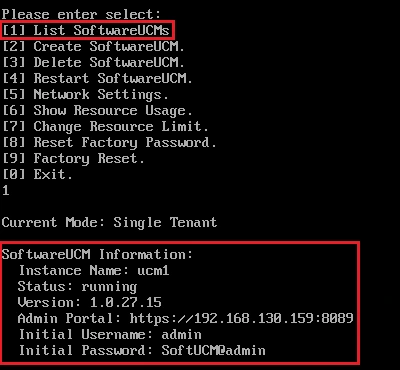
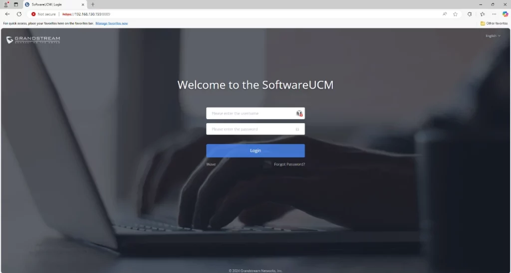
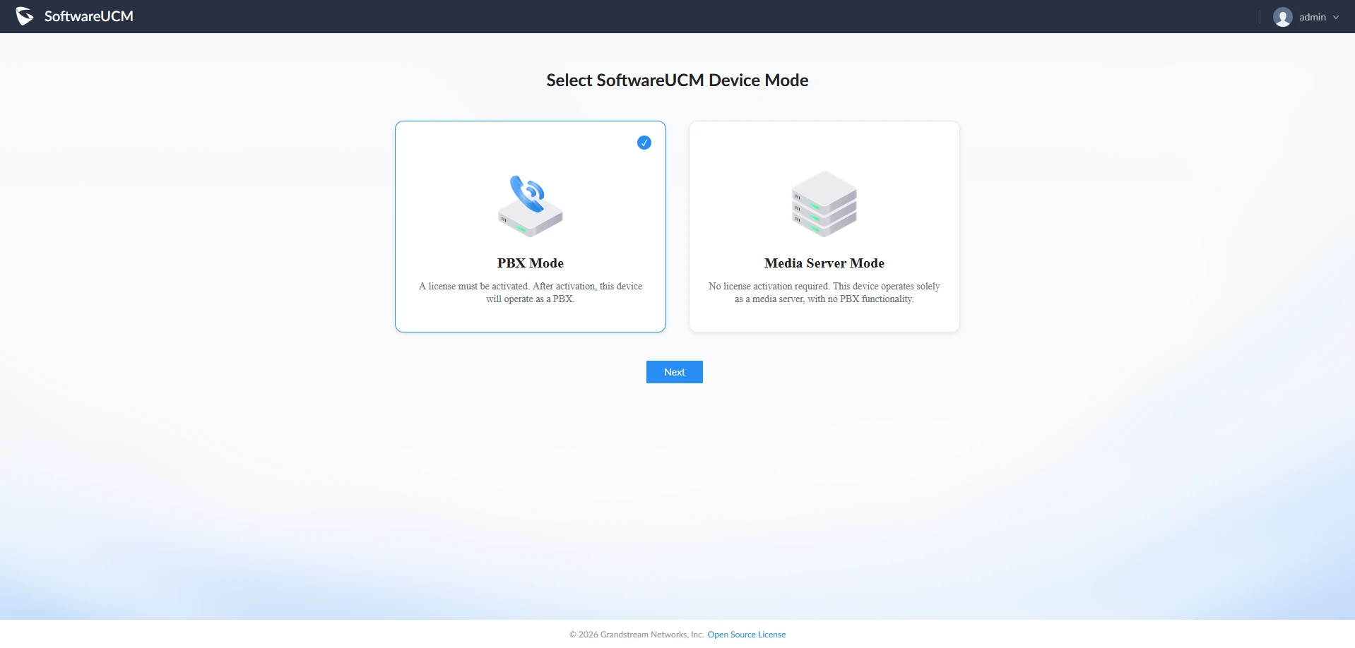
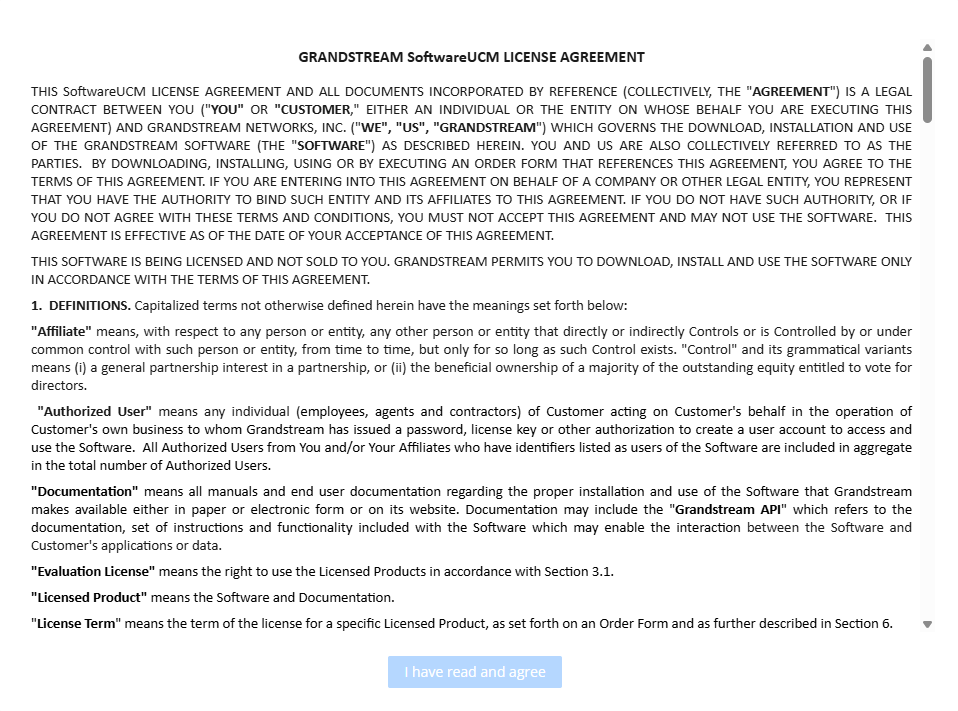
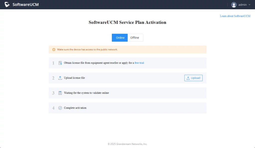
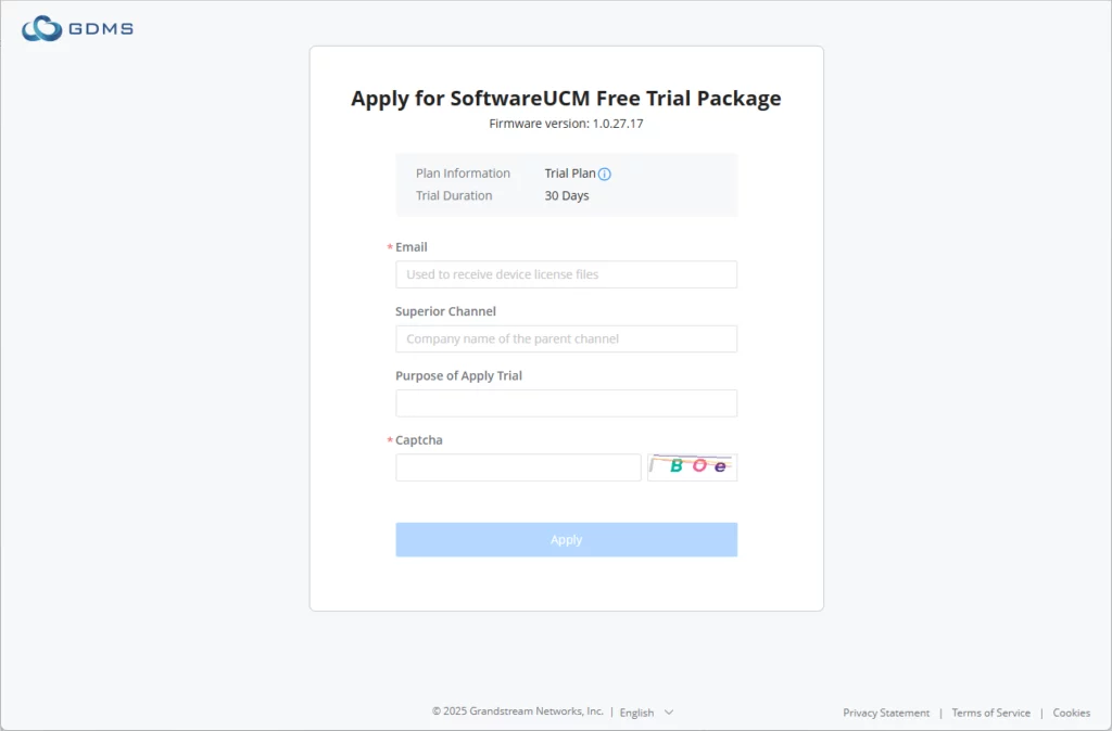
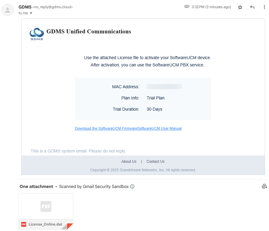
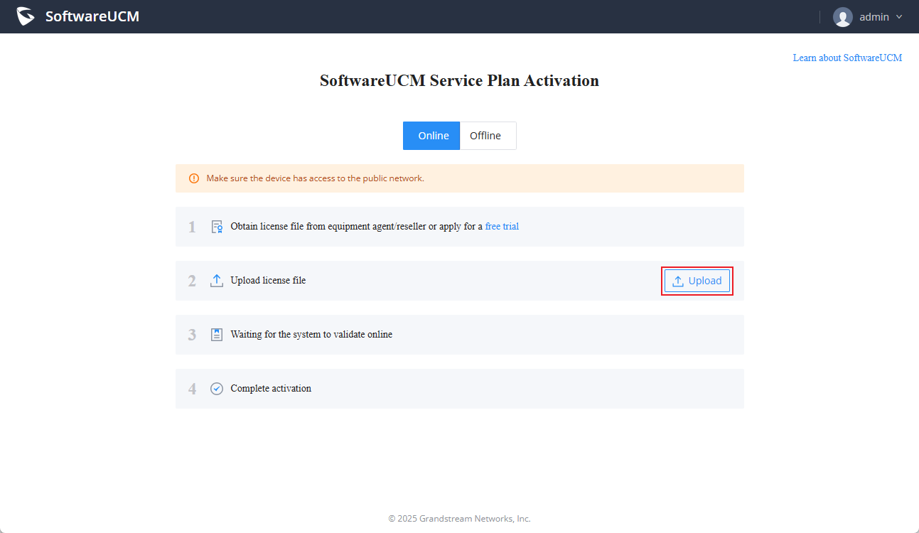
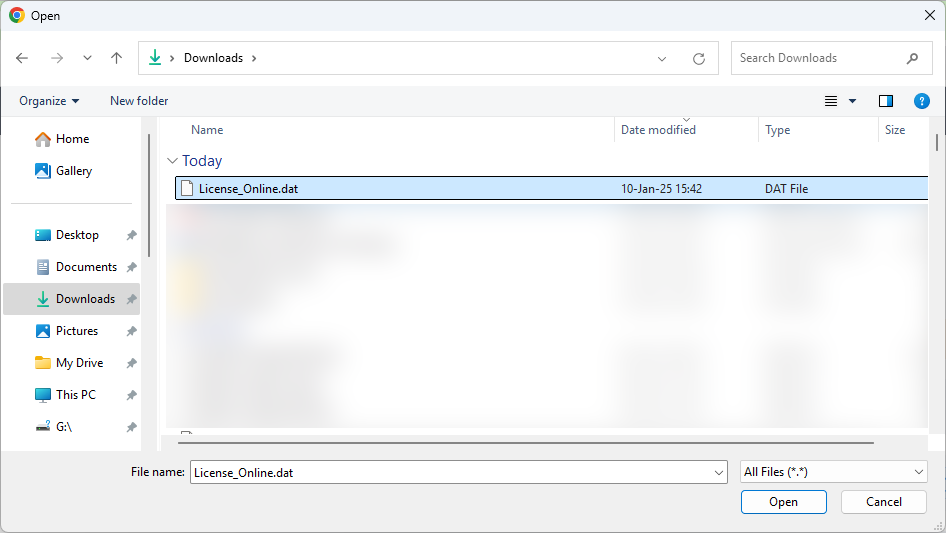
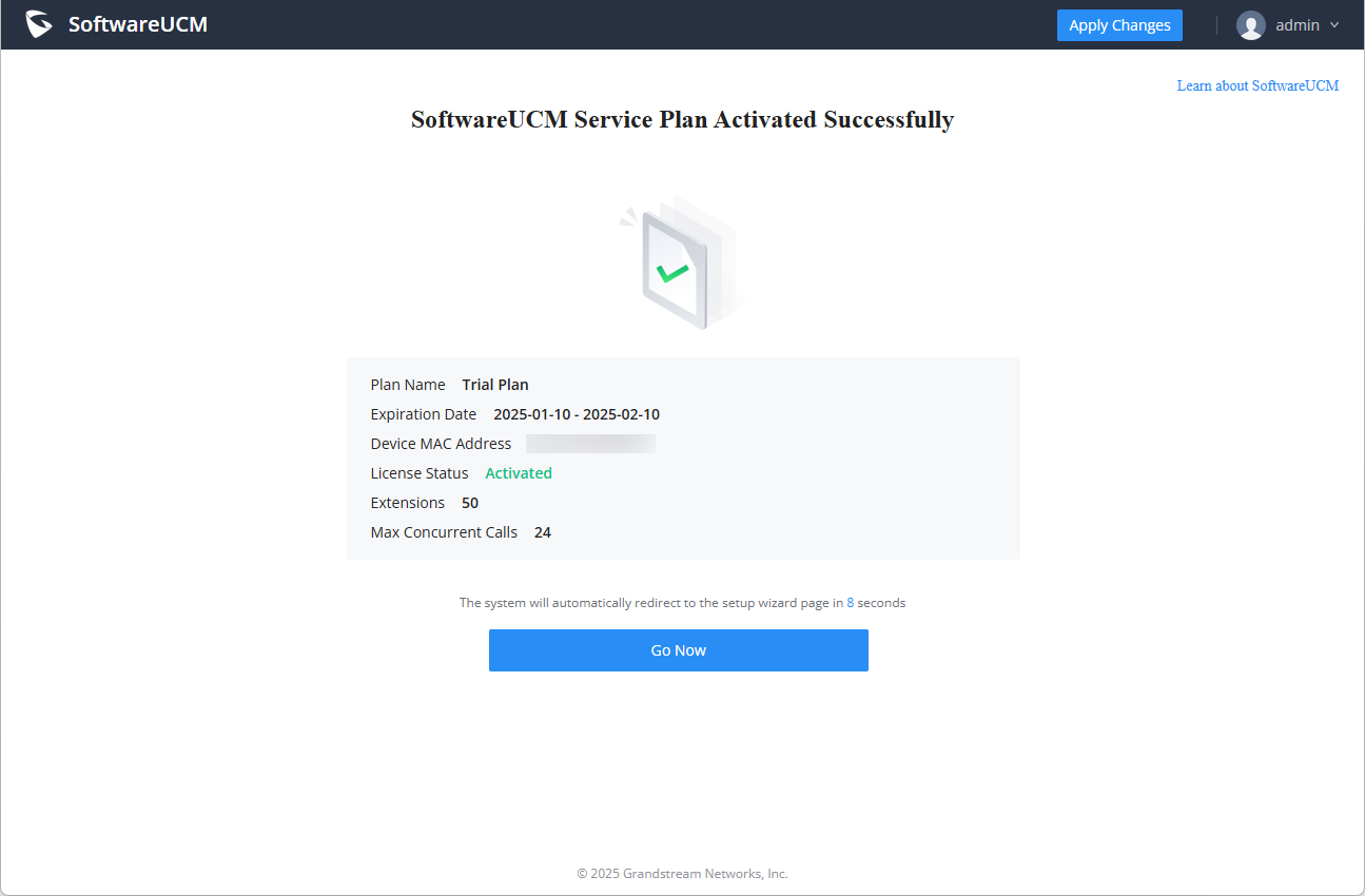
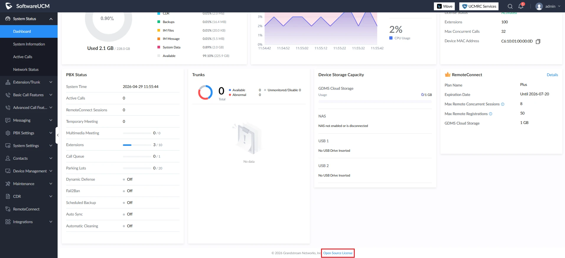
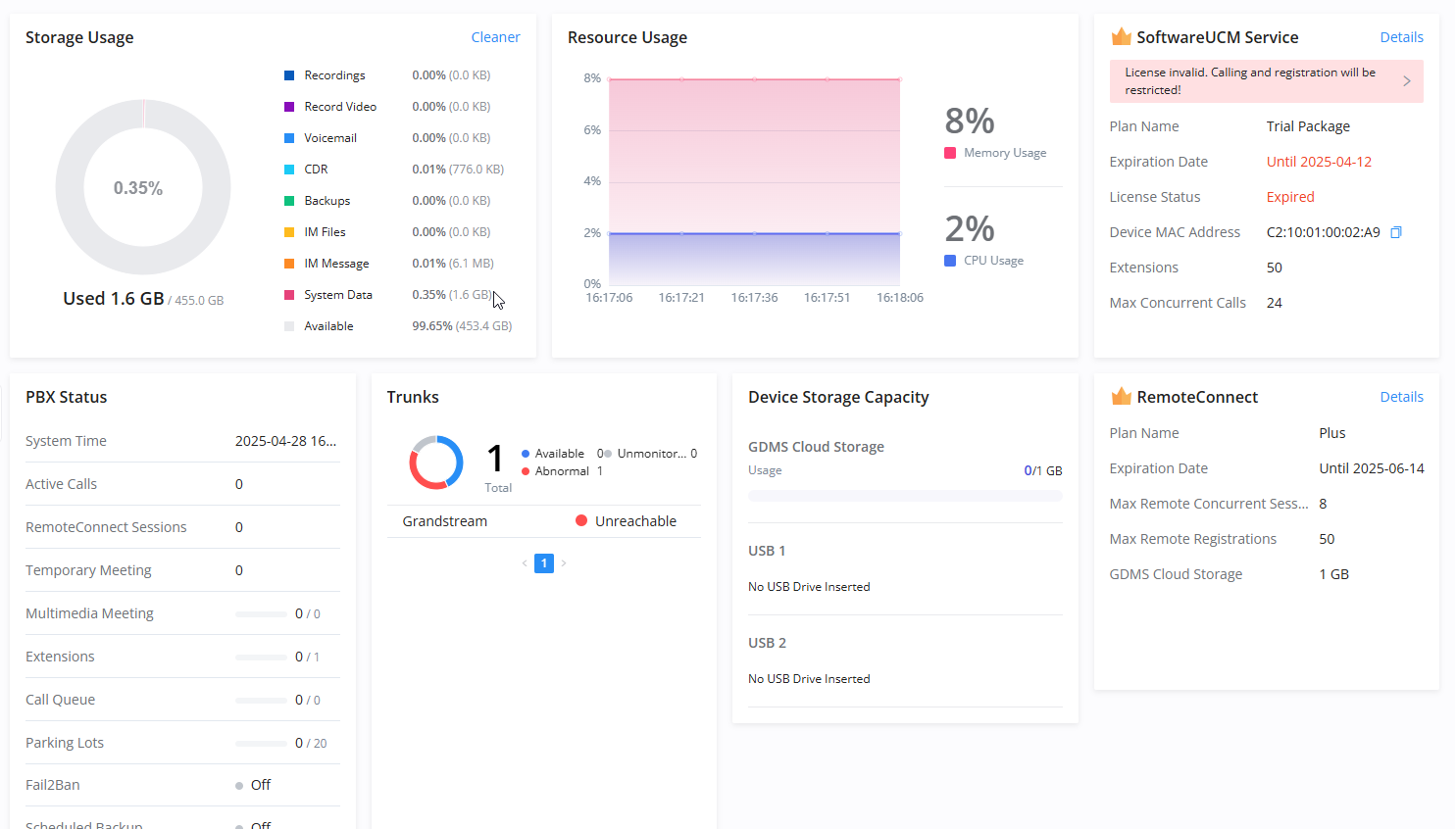
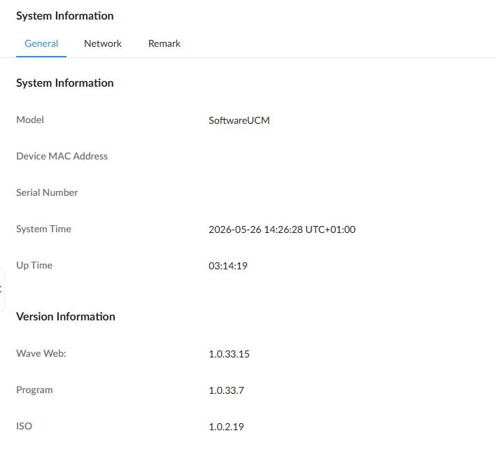
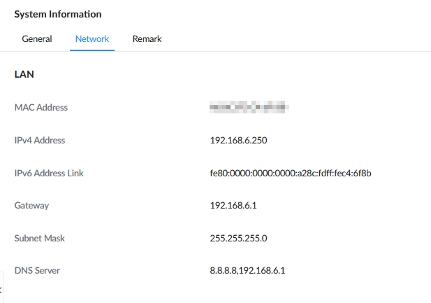
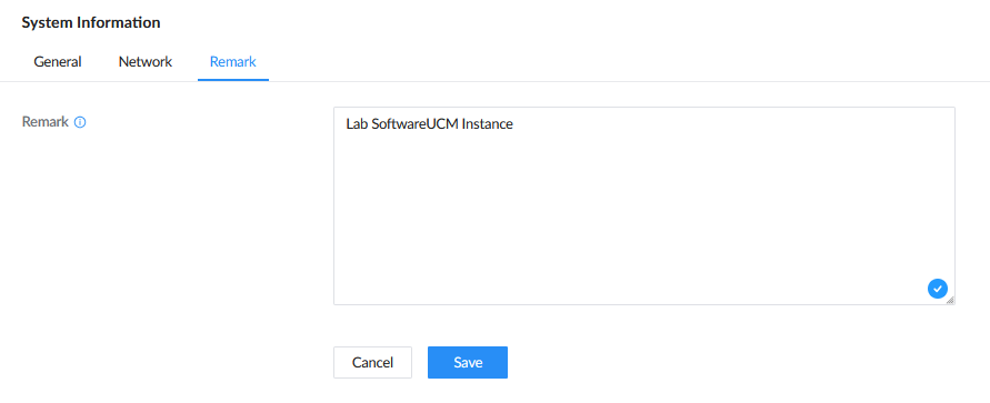
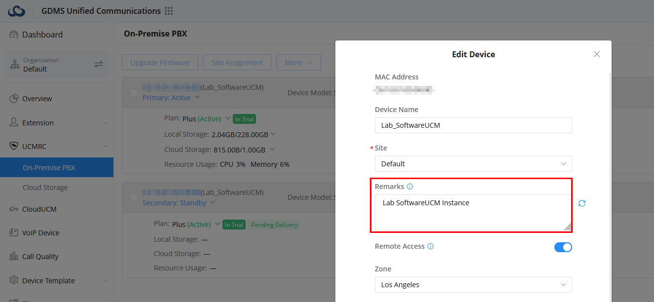
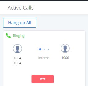
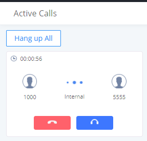
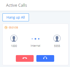
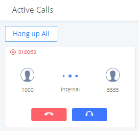
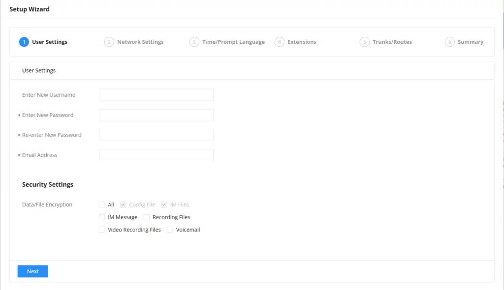
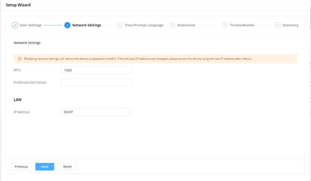
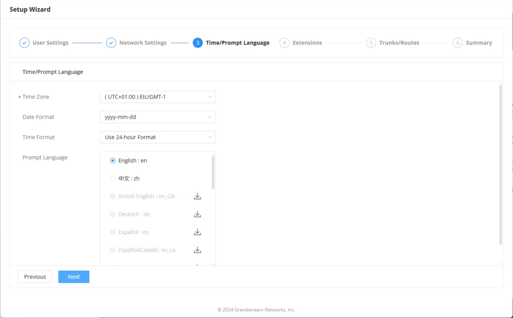
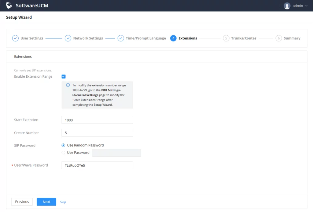
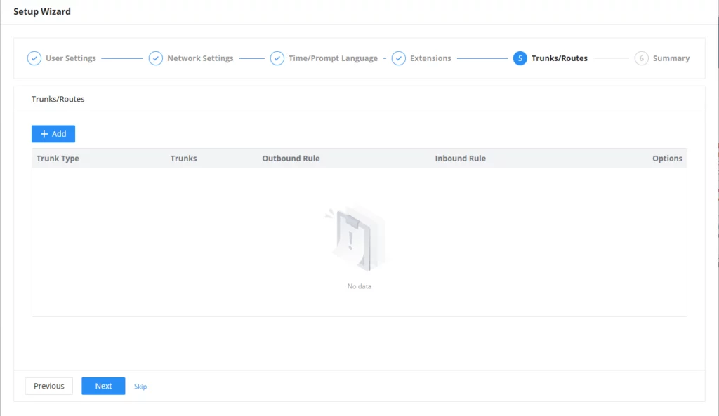
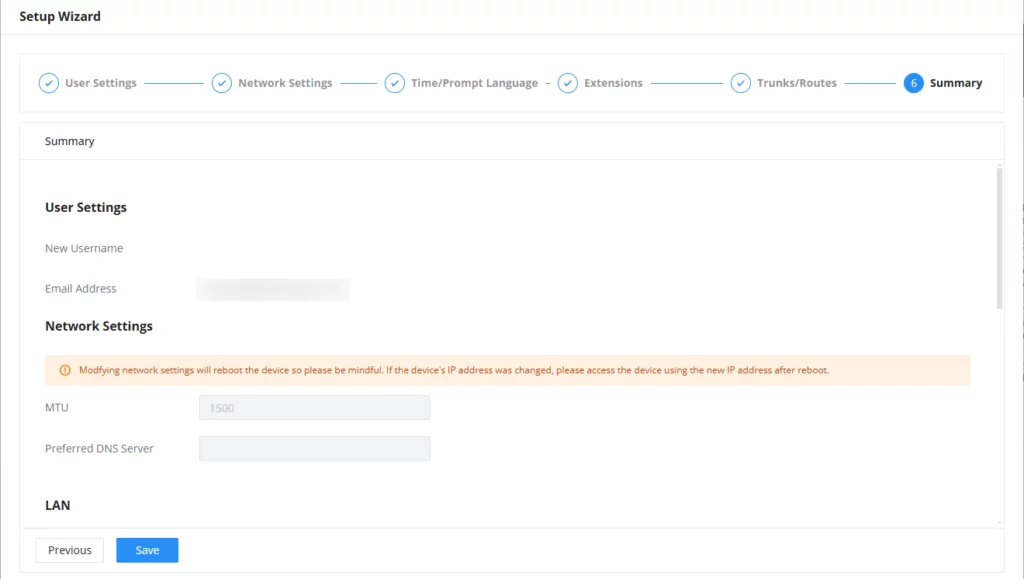
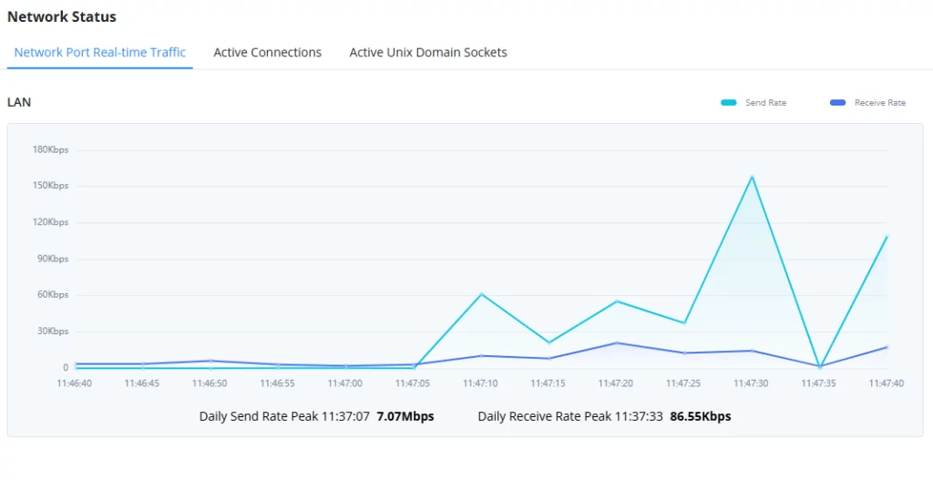
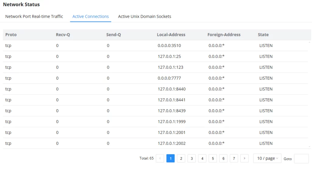
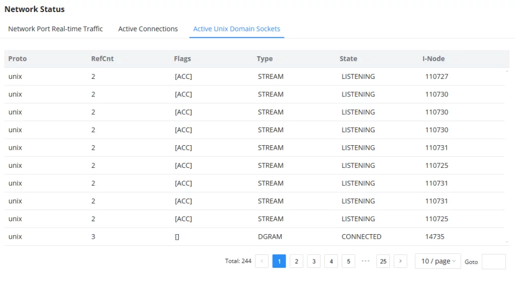
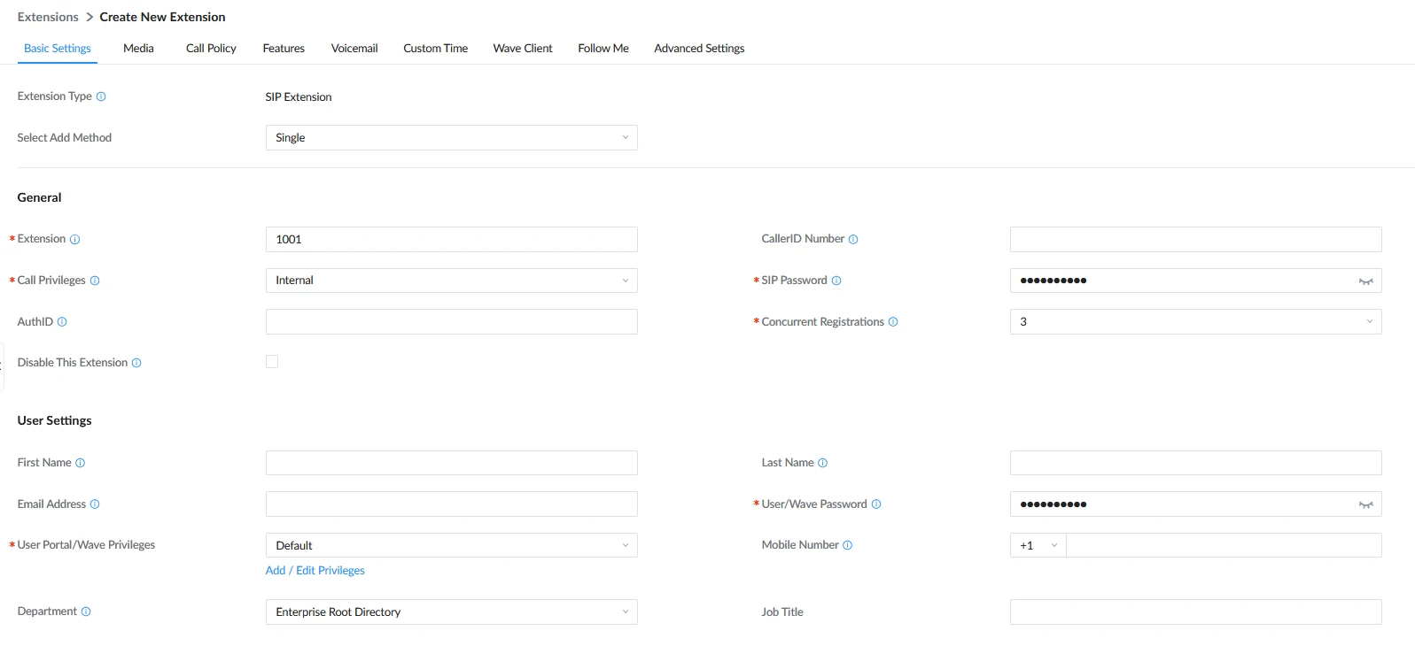
 , “Reboot”
  and “Delete”
  are available per extension. Users can search for an extension by specifying the extension number to find an extension quickly.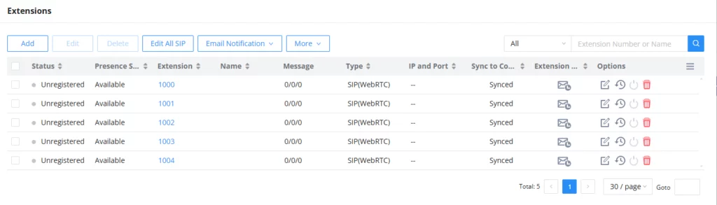
 Green: Idle
 Blue: Ringing
 Yellow: In Use
 Grey: Unavailable (the extension is not registered or disabled on the PBX)
 to start editing the extension parameters.
 to reset the extension parameters to default (except concurrent registration).
 to send NOTIFY reboot event to the device that has a SoftwareUCM extension already registered. To successfully reboot the user.
 to delete the extension. Or select the checkbox of the extension and then click on “Delete Selected Extensions”.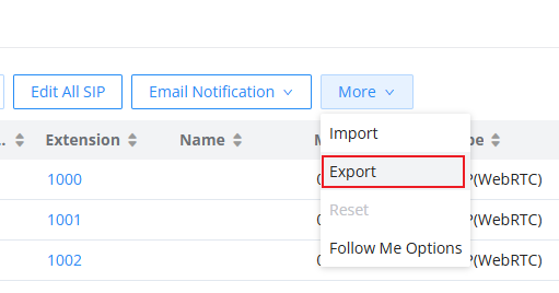
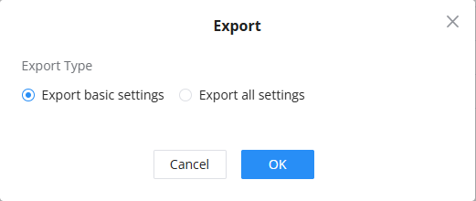
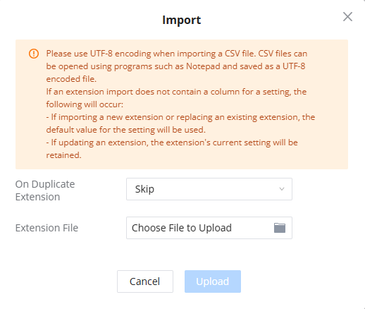


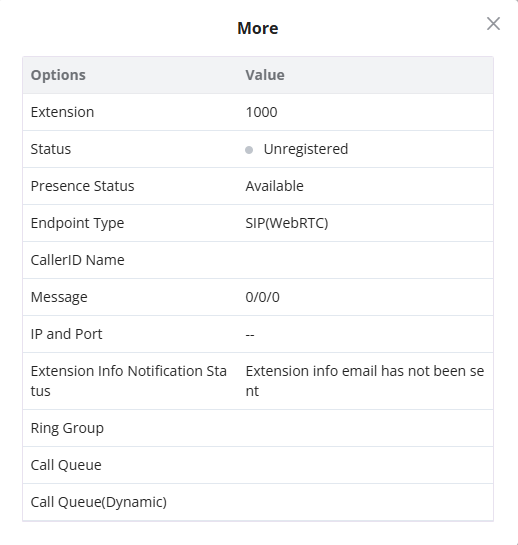
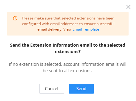
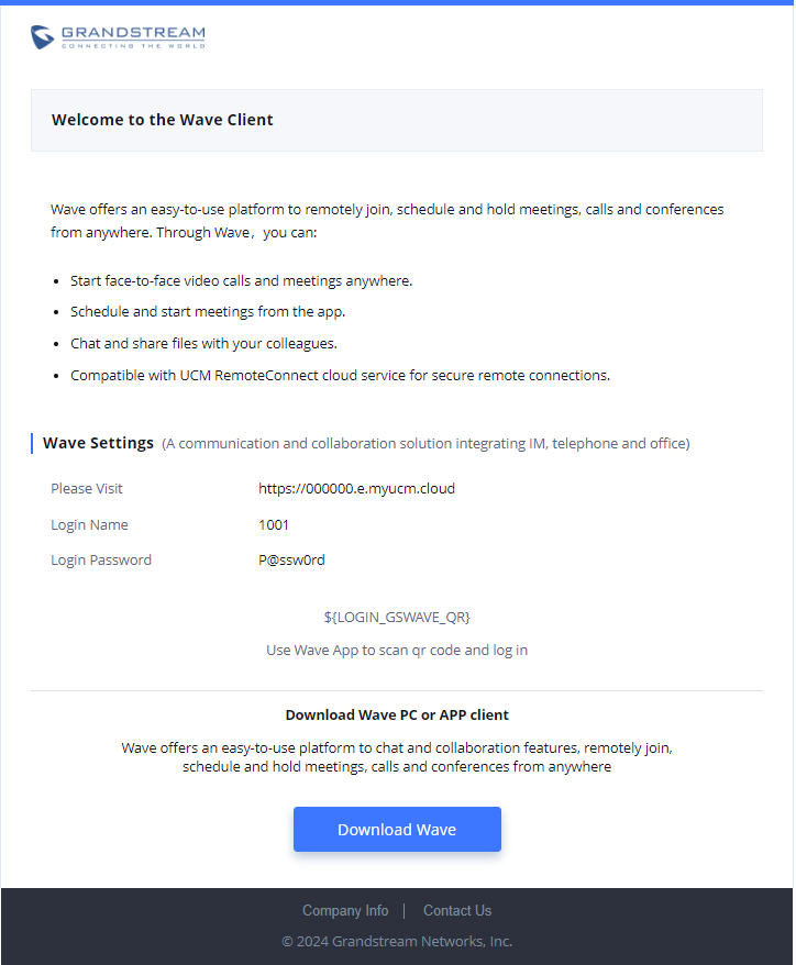
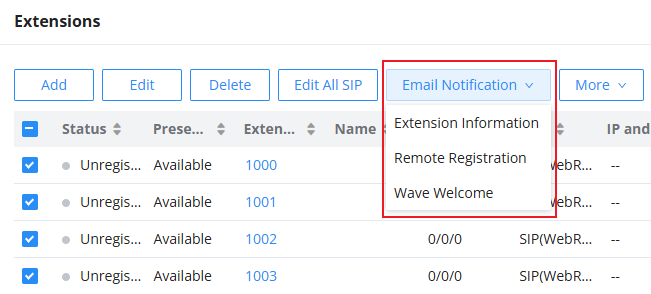
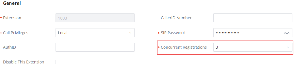


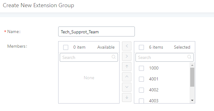


 to change the ringing priority of the members selected on the group.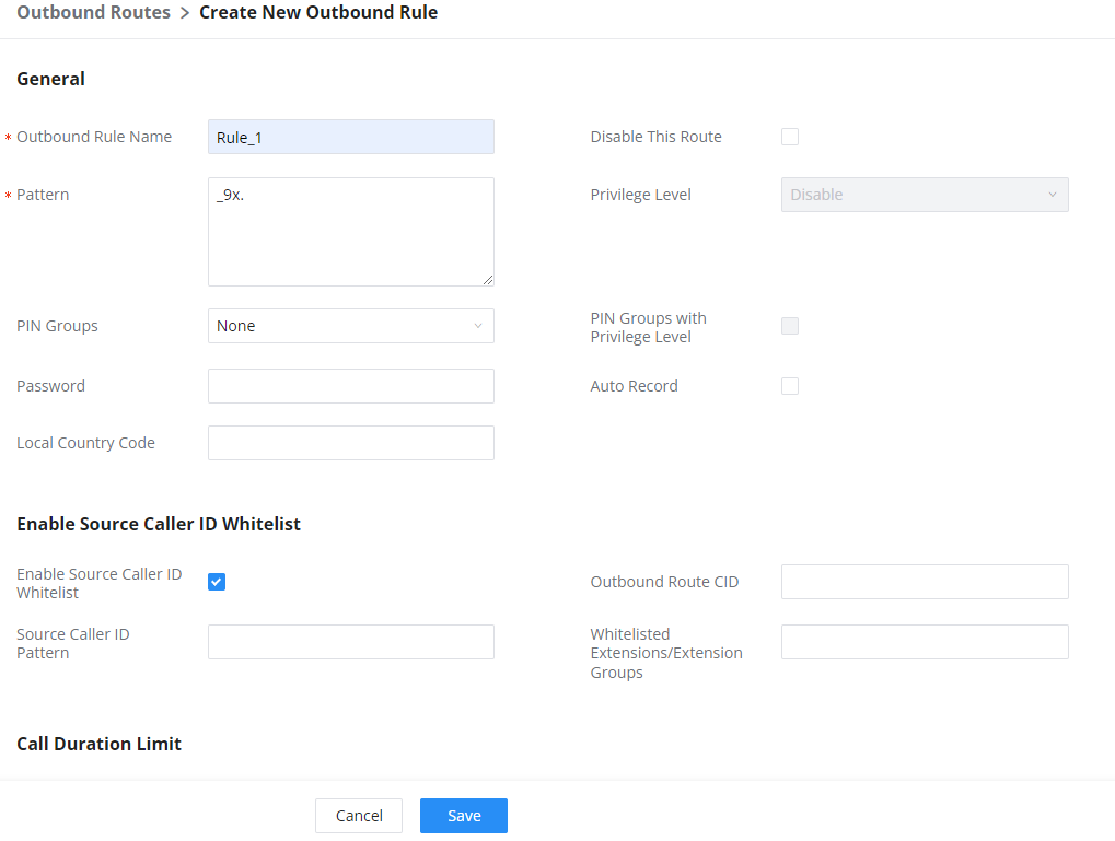
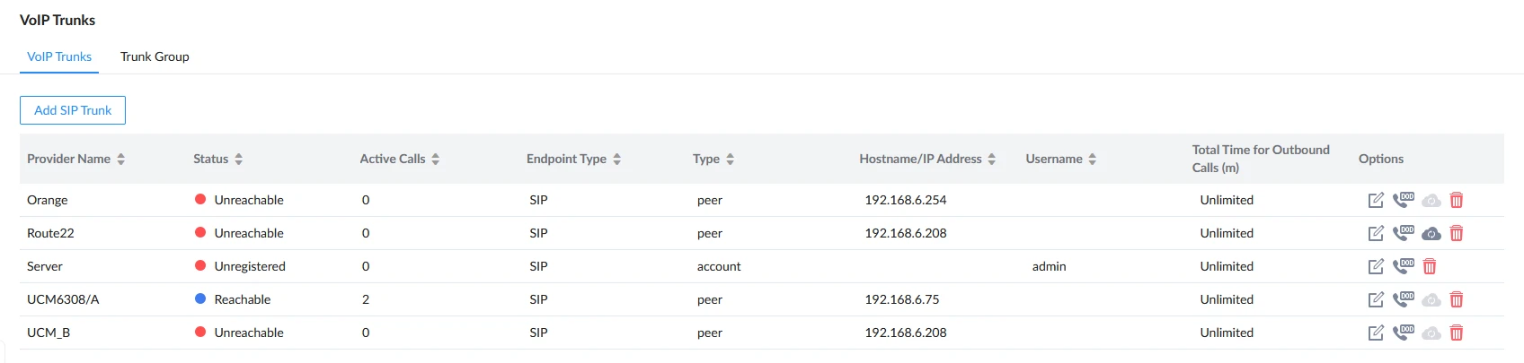
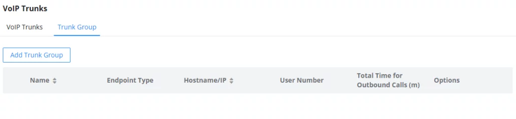
 button and configuring the username, password, and authentication ID fields.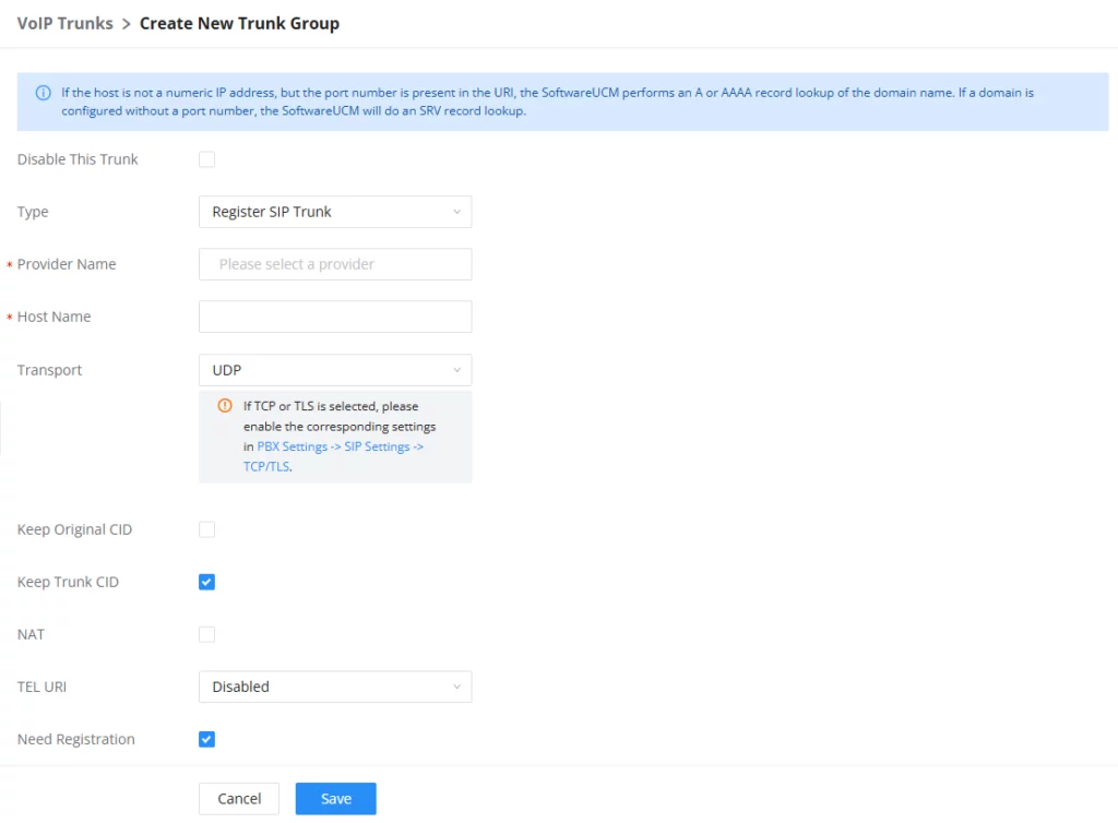
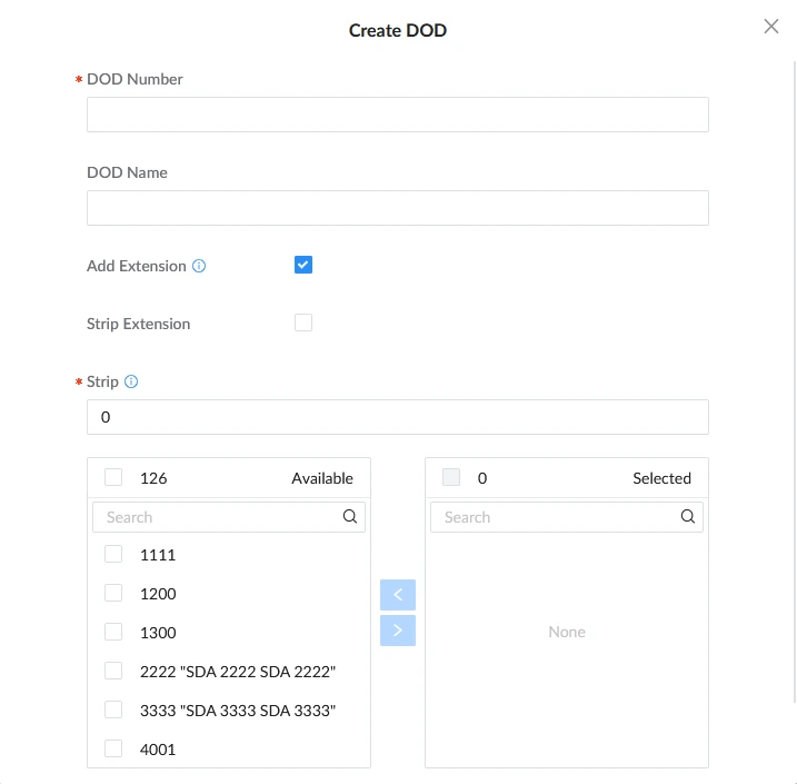
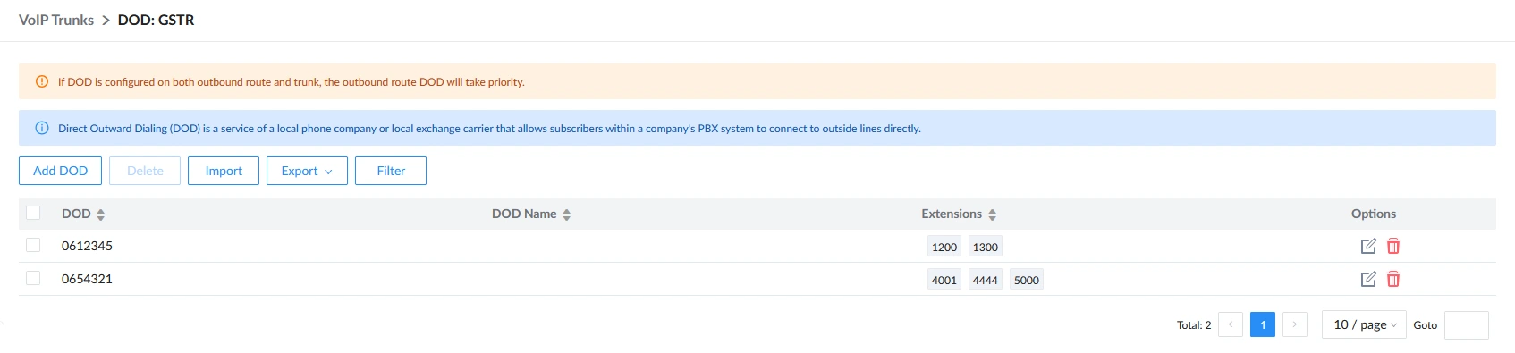
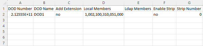

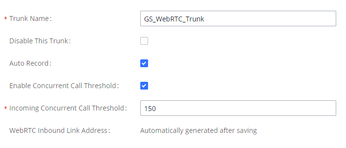
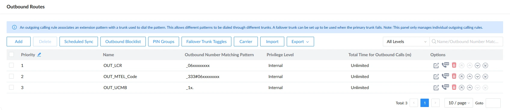
 on the Outbound Routes page.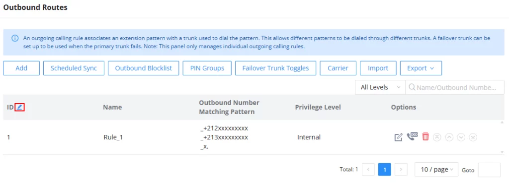
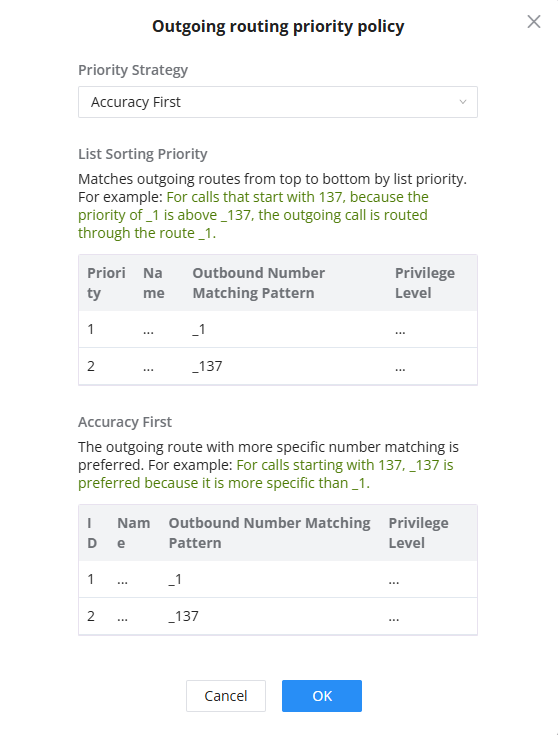
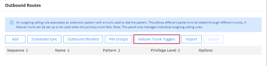
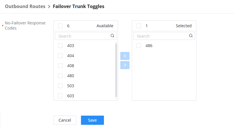
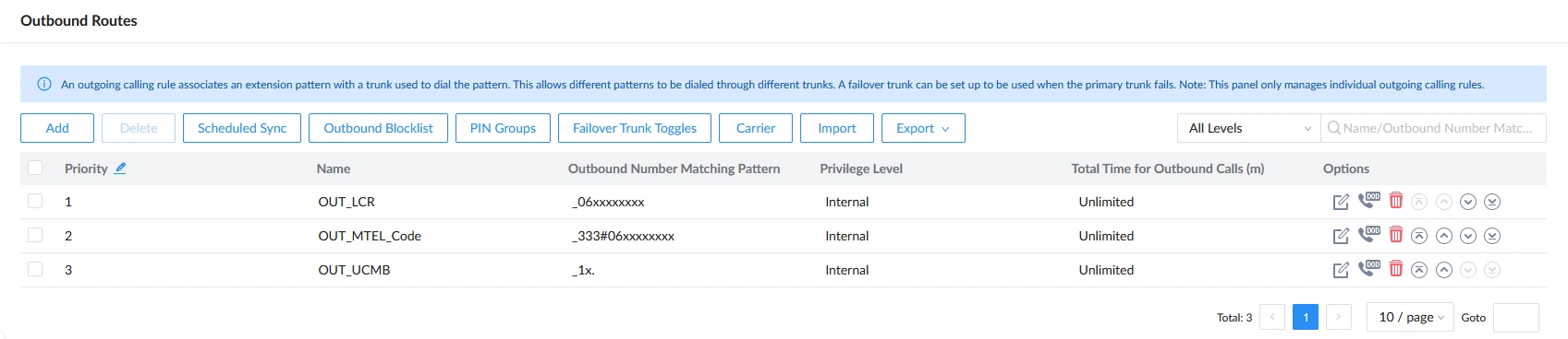


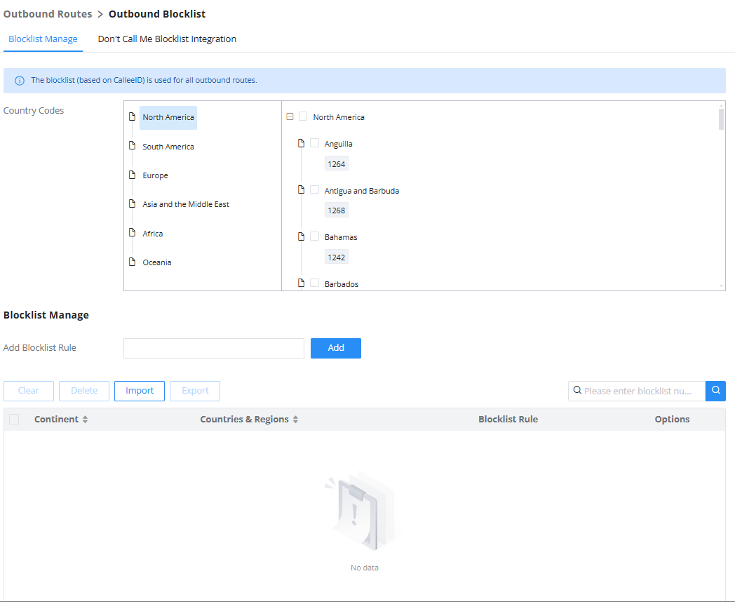
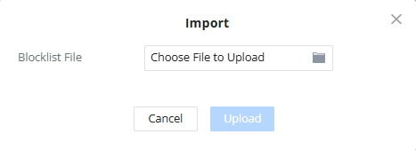
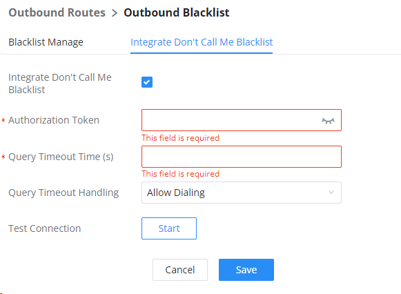
 , the following figure shows to configure the new PIN.
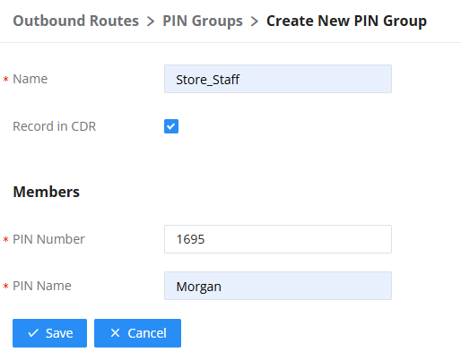
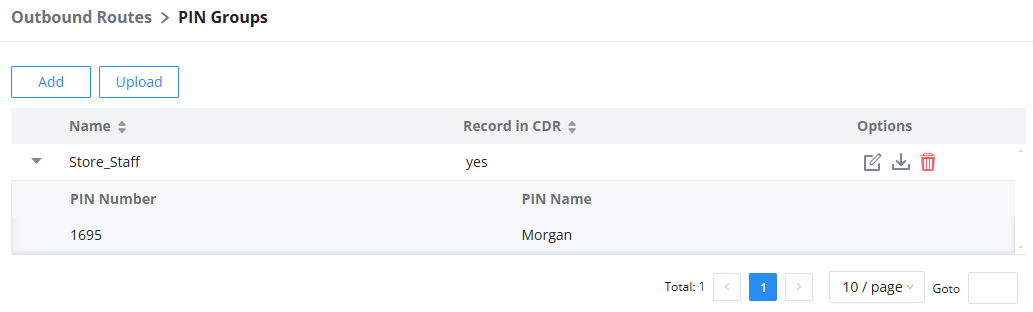
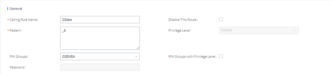
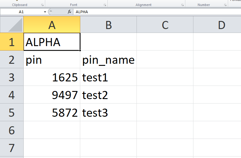
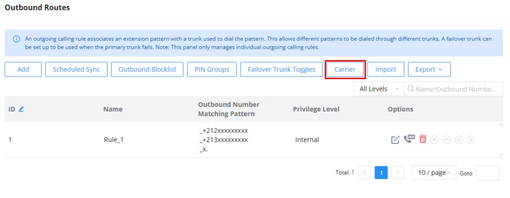
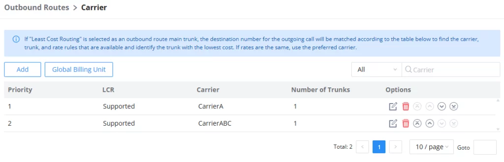
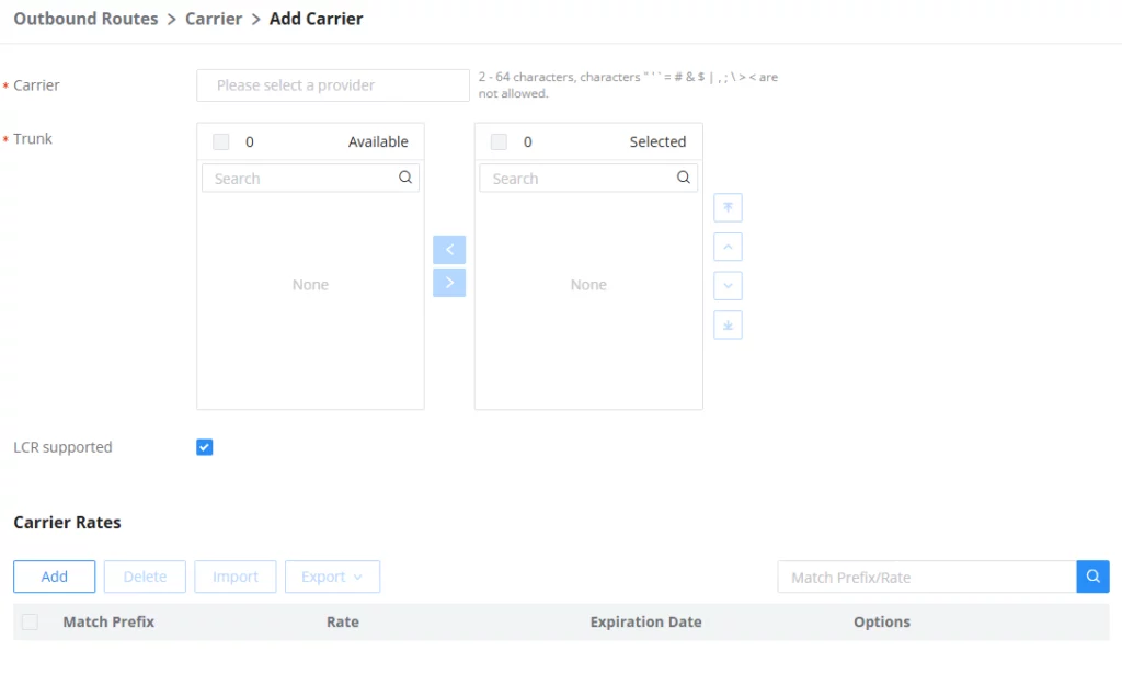
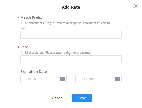

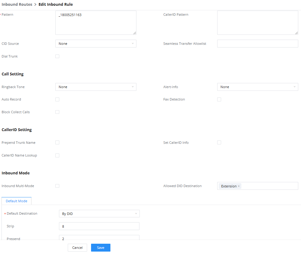
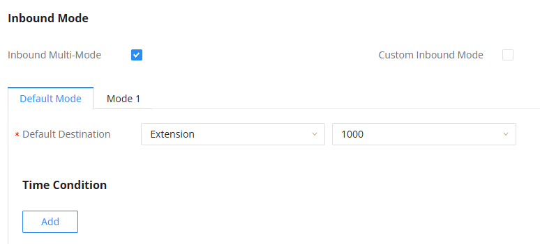
 under the “Inbound Routes” page, check the “Enable Inbound Multi-Mode” option, and change “Inbound Default Mode” and “Inbound Mode 1” values (By default, *61 and *62 respectively).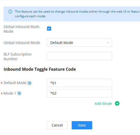
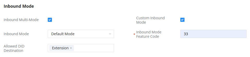


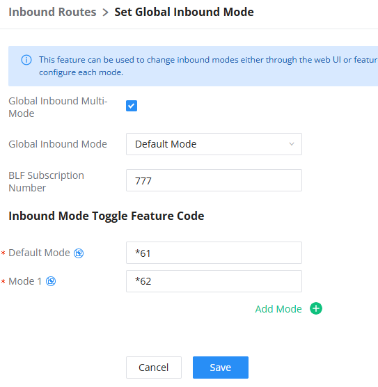
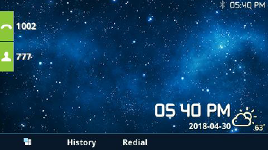
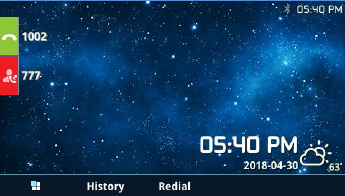

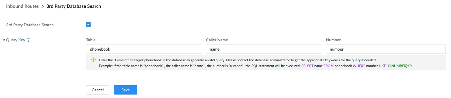



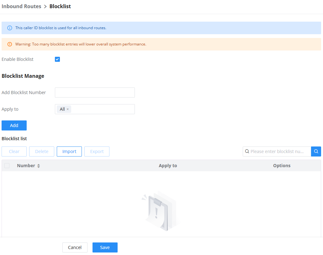
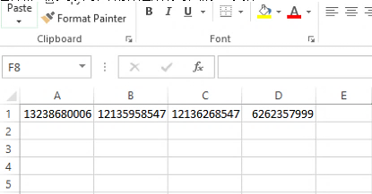


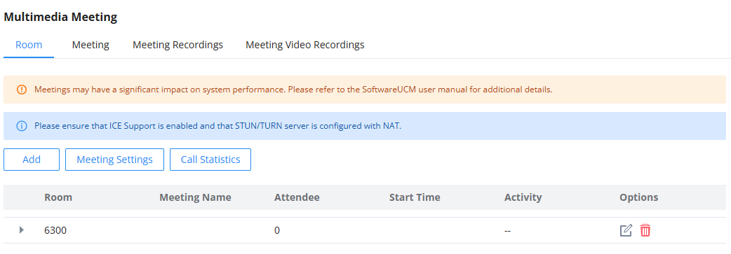


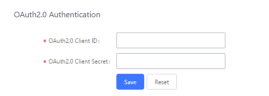
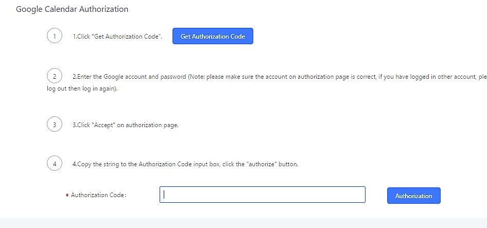
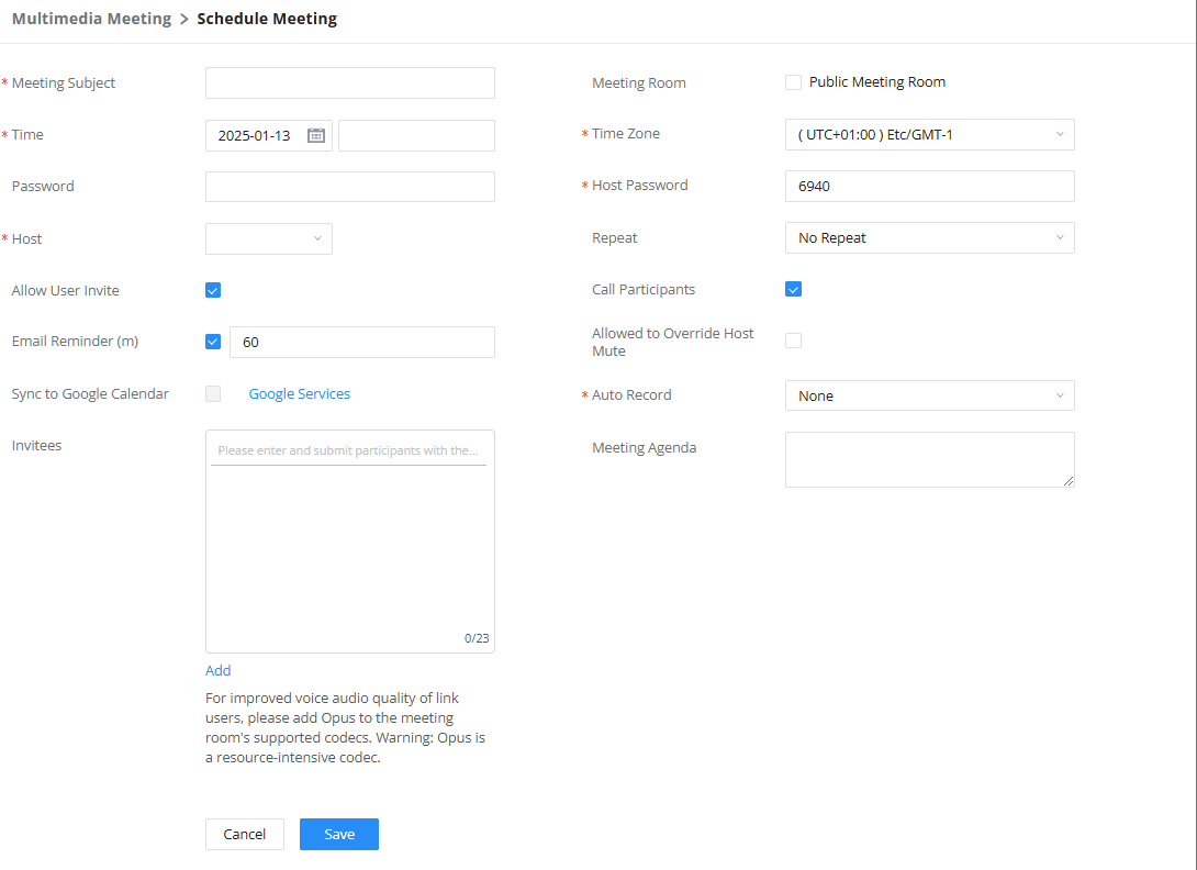
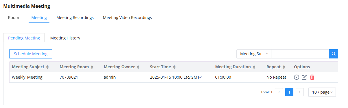
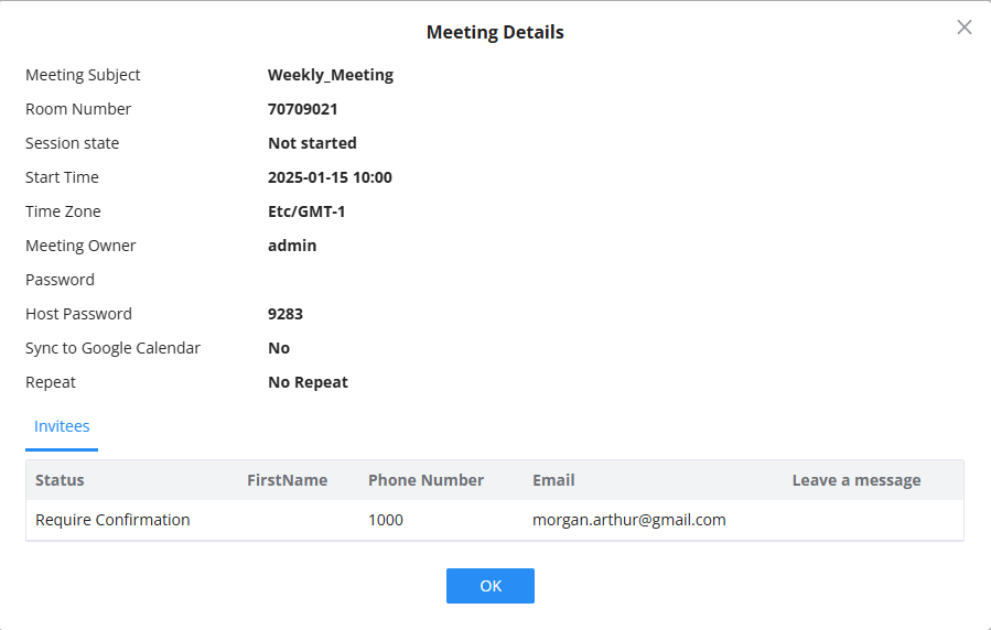
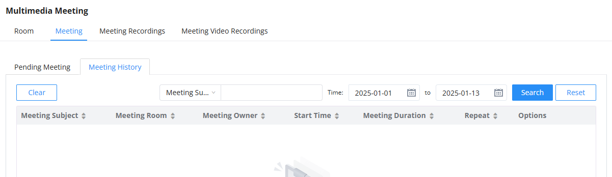
 to download the Meeting Report of the meeting.
 to reschedule the Meeting.
 to download the Meeting Report of the meeting.
 to reschedule the Meeting.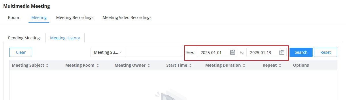
 to download the recording or click on
  to delete the recording. Users could also delete all recording files by clicking on “Delete All Recording Files” or delete multiple recording files at once by clicking on “Delete” after selecting the recording files.
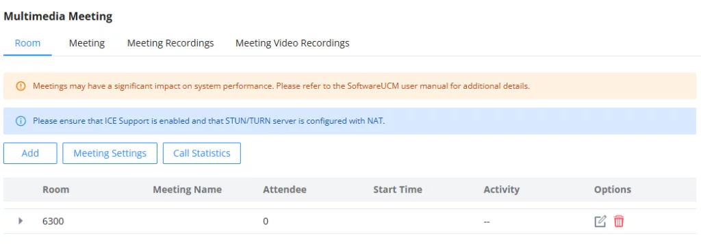
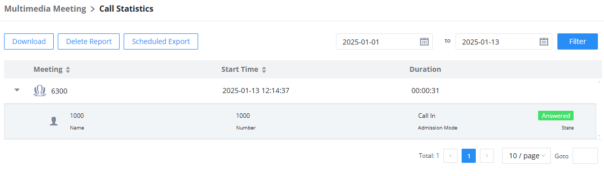
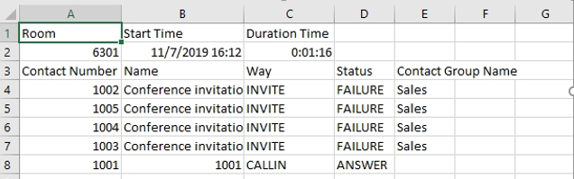


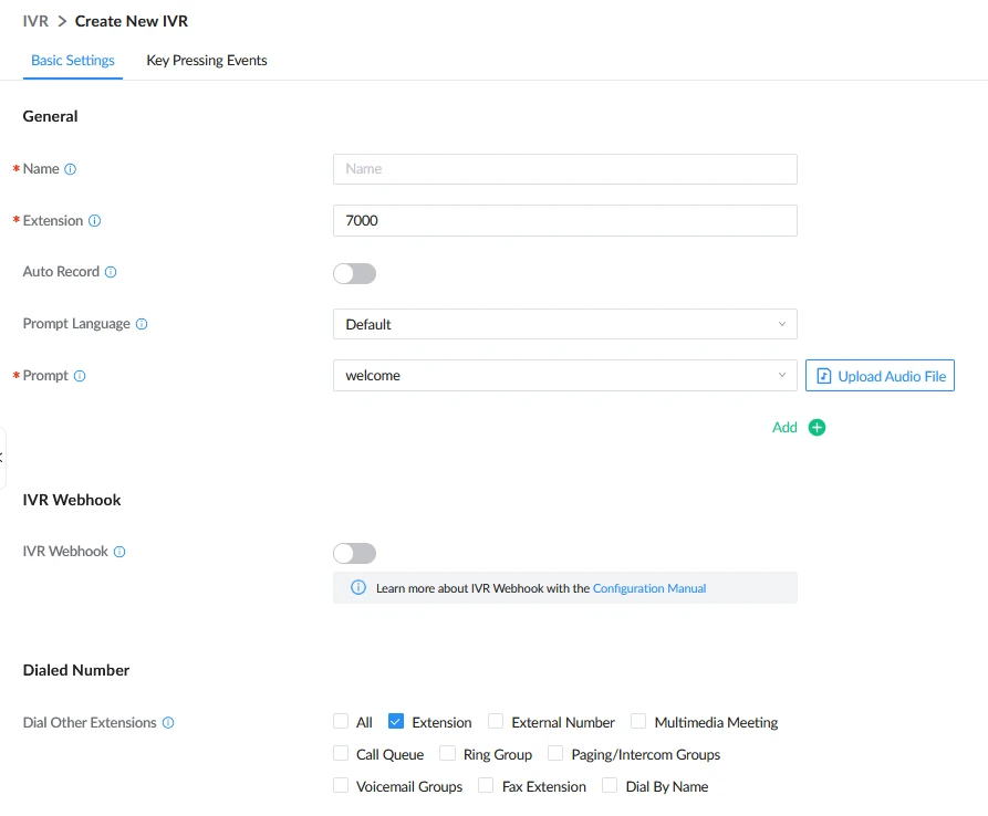
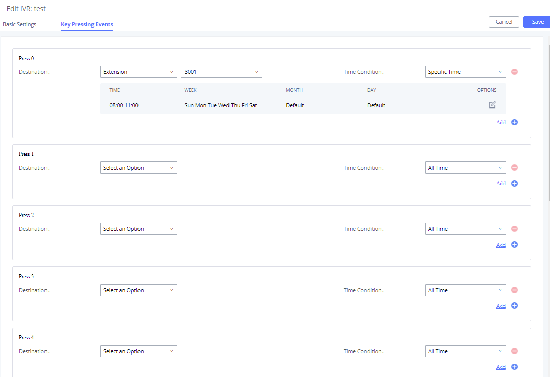
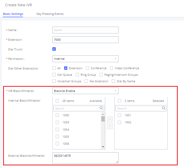
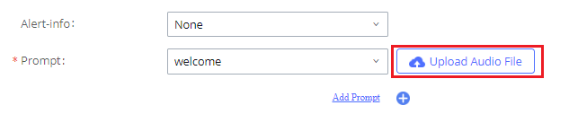
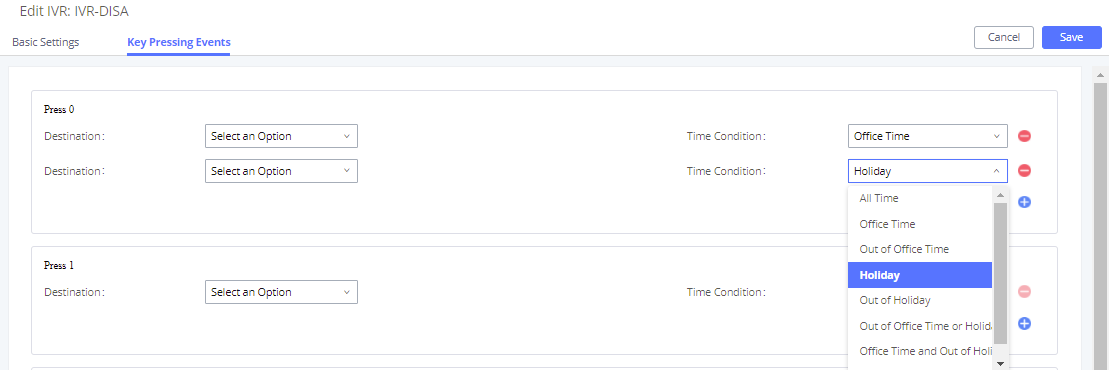
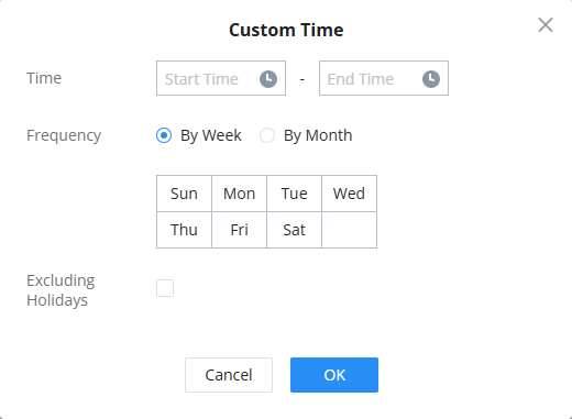
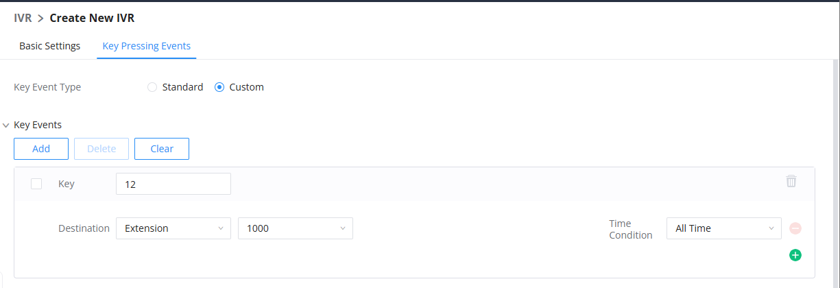
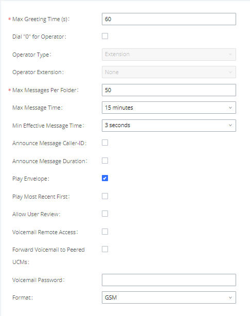
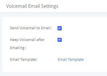
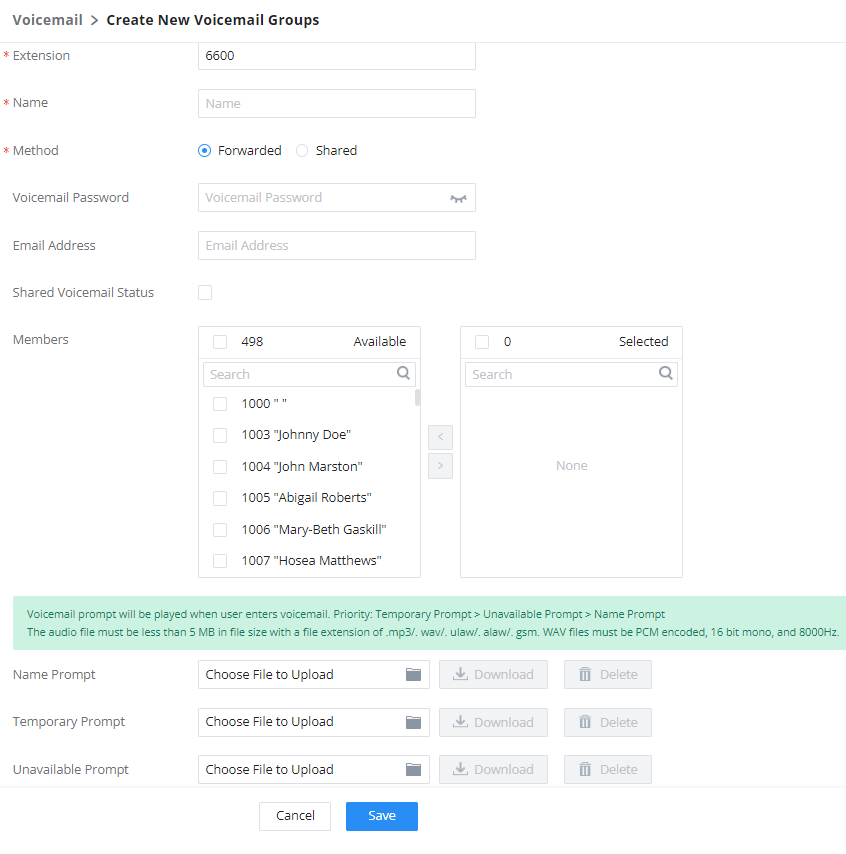



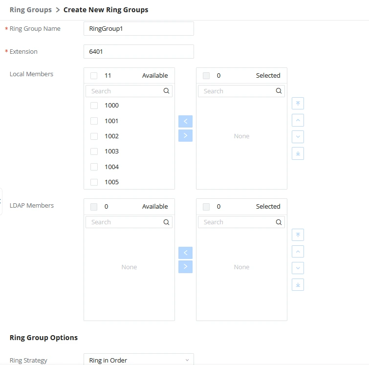

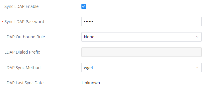

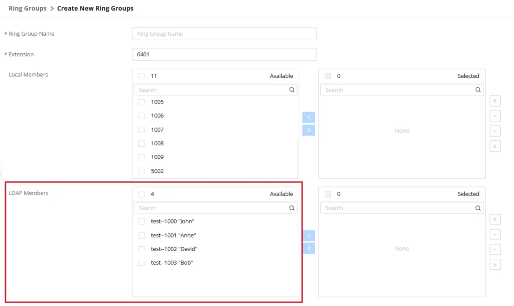
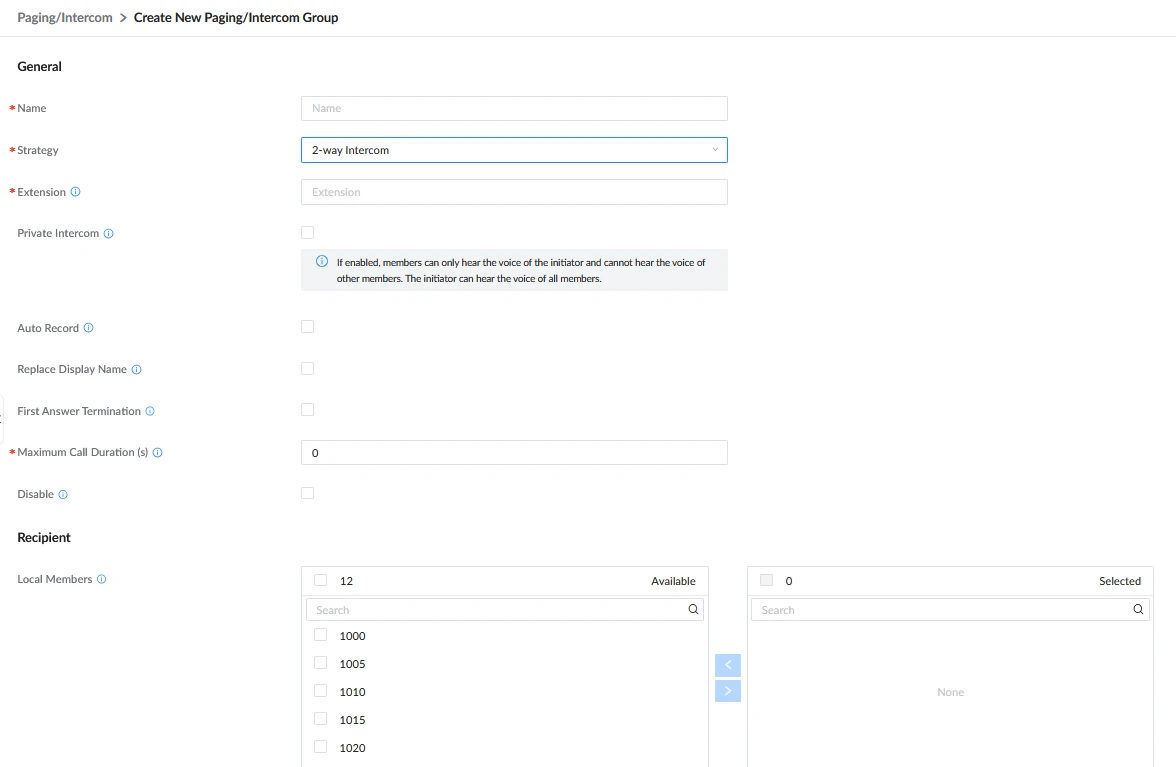
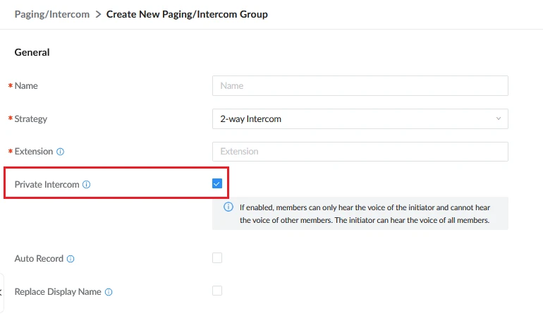
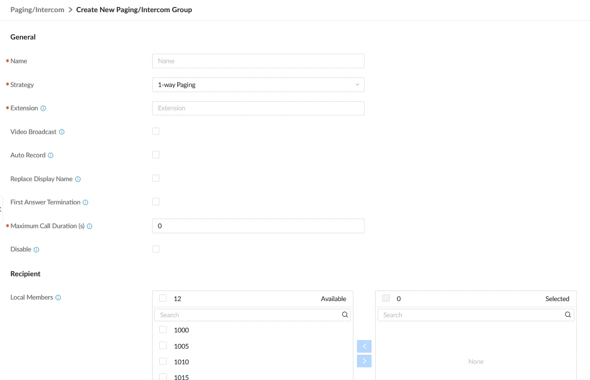

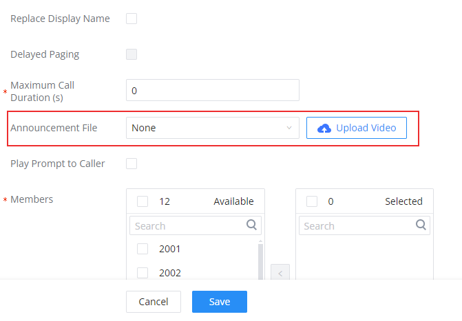
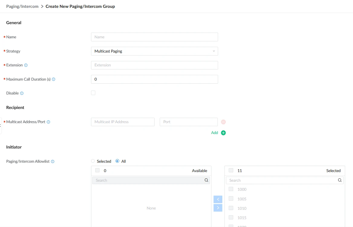
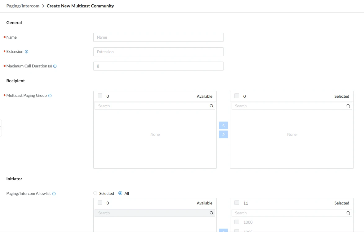
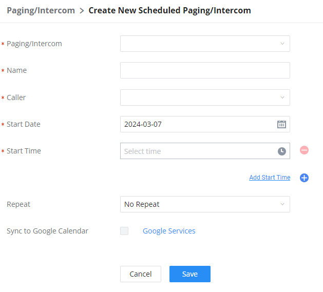
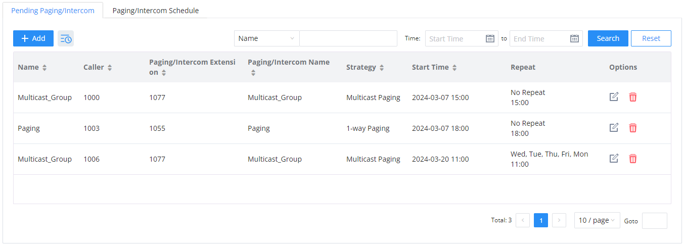
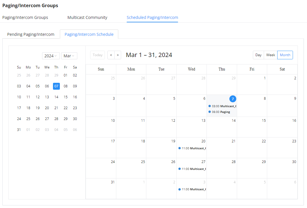

 to modify an existing call queue.
 to remove a call queue.


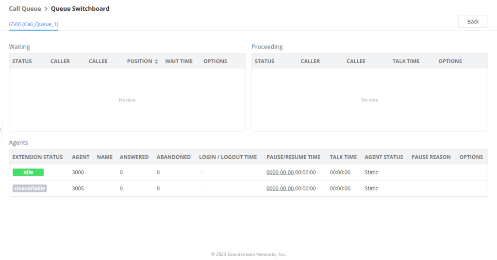
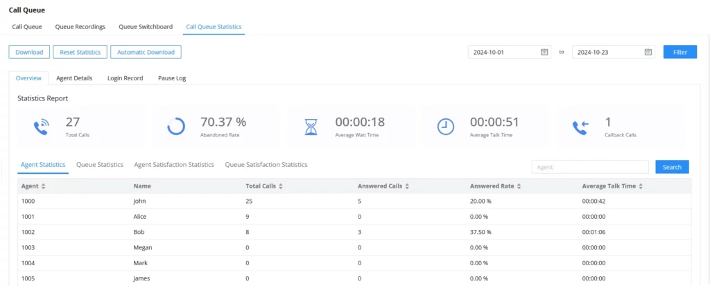
 button. They can also set up automatic email deliveries of these statistics at regular intervals by clicking on
 button.


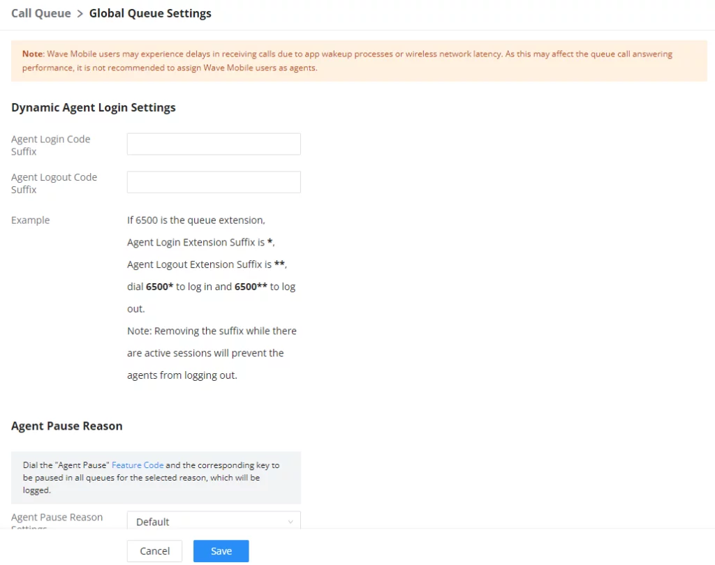
 . Then decide from one digit up to four digits combination used for Speed Dial and select a dial destination from “Default Destination”. The supported destinations include extension, voicemail, conference room, voicemail group, IVR, ring group, call queue, page group, DISA, Dial by Name and external number.






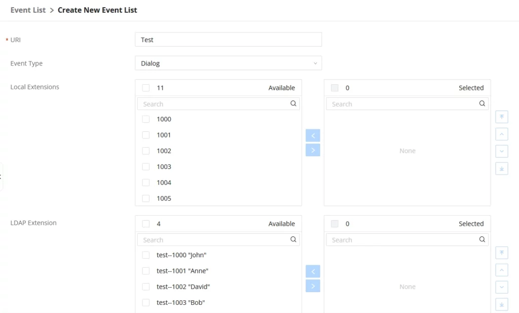


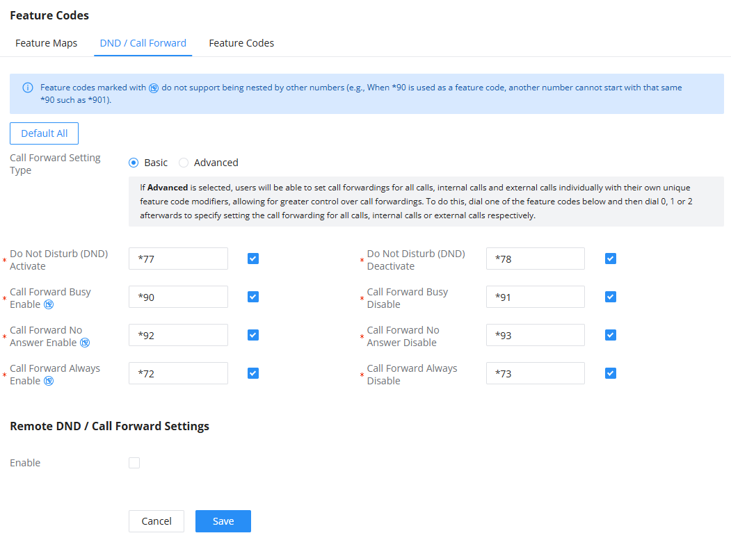
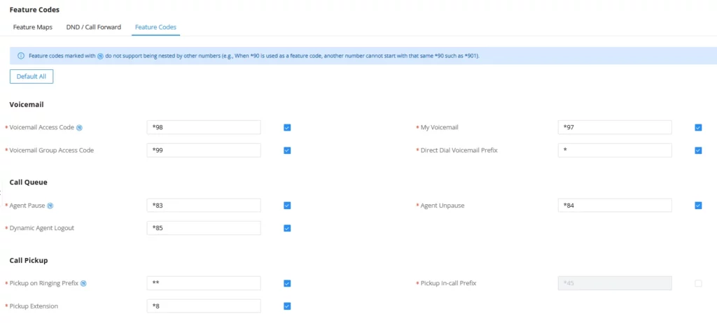

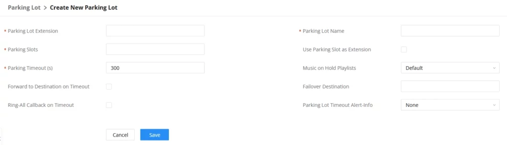



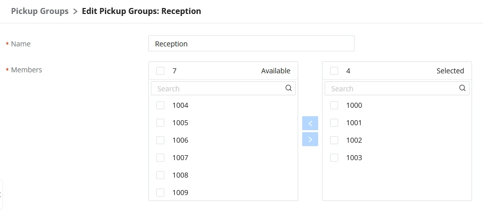
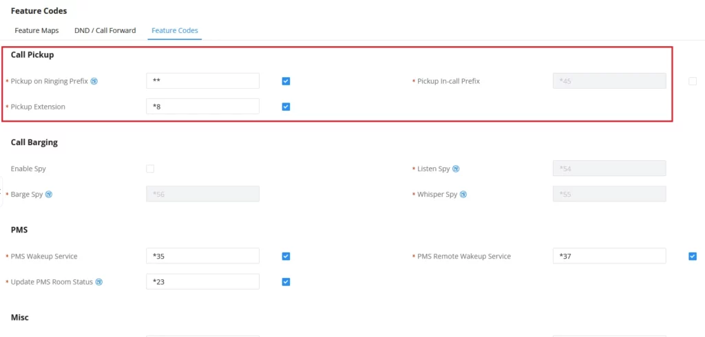
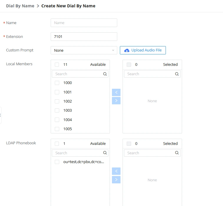
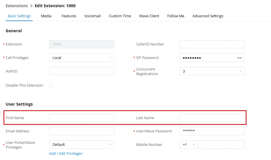
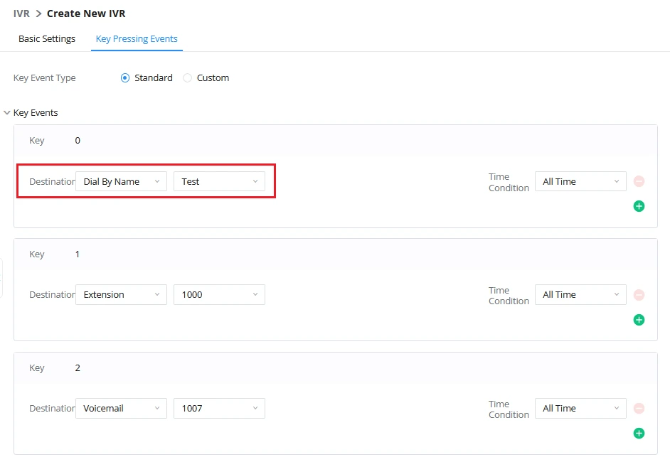
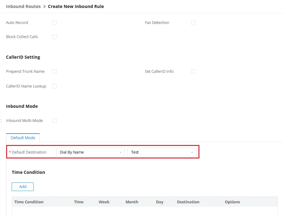


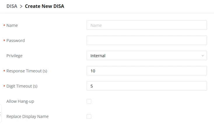
 . Configuration parameters are listed in the following table.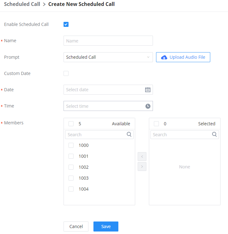
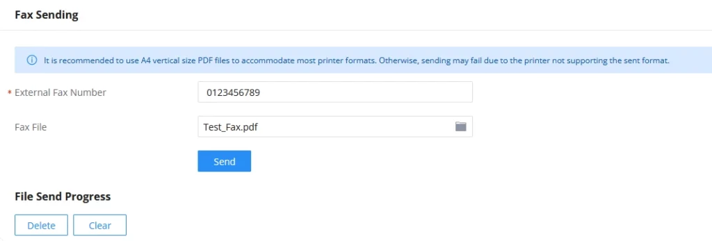
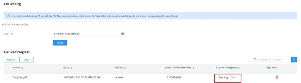
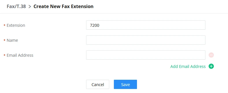


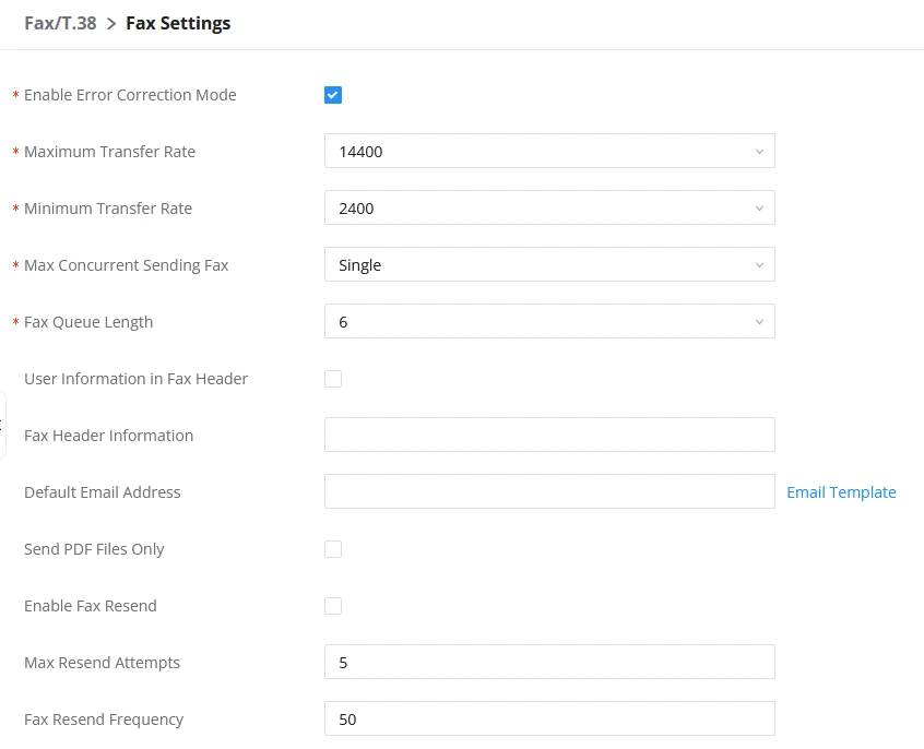
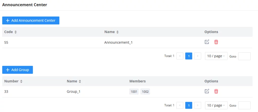
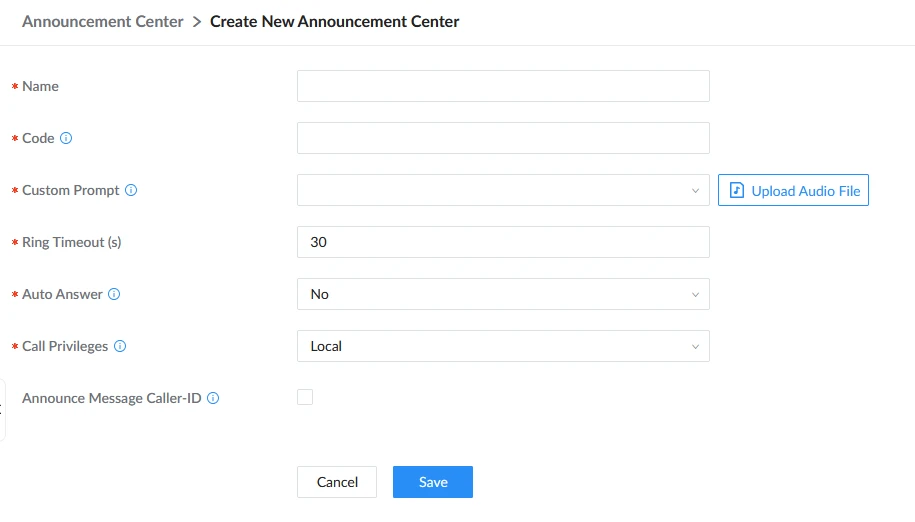


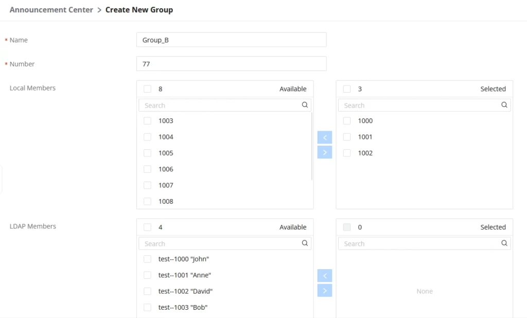


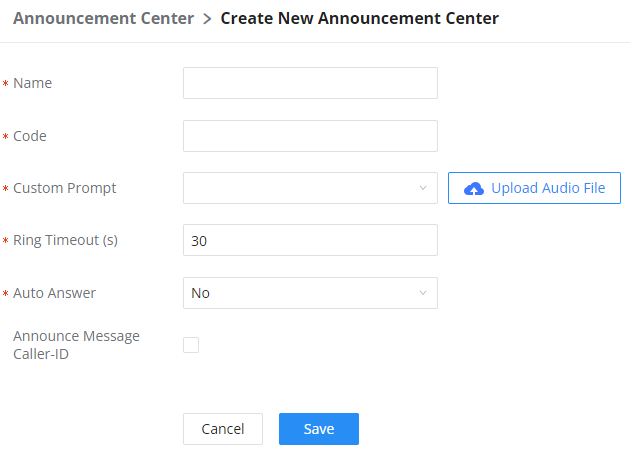
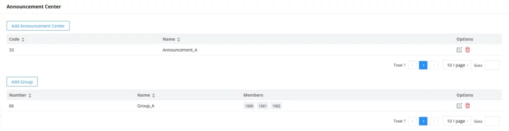
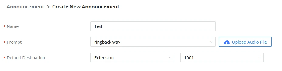
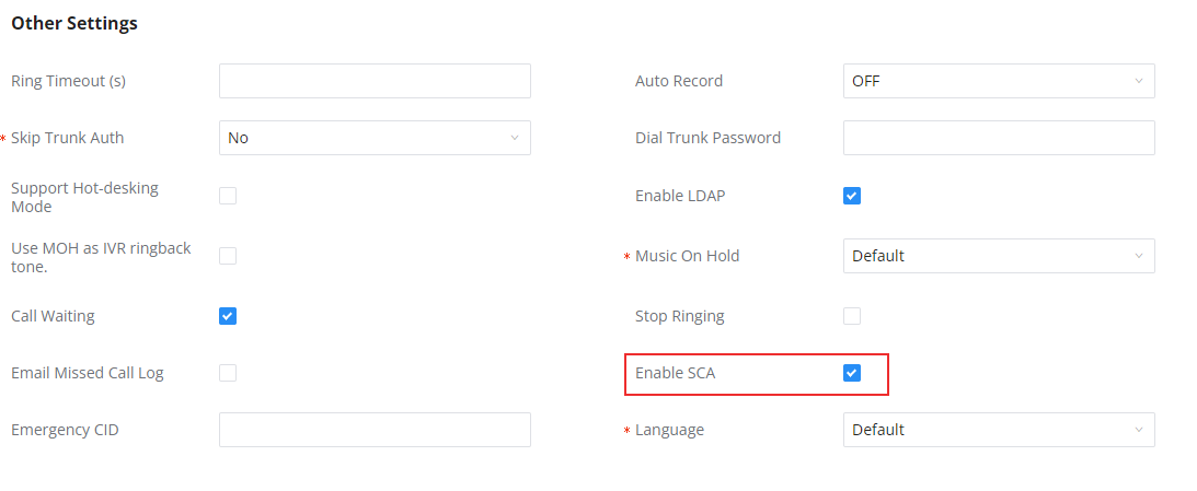

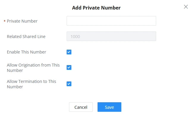
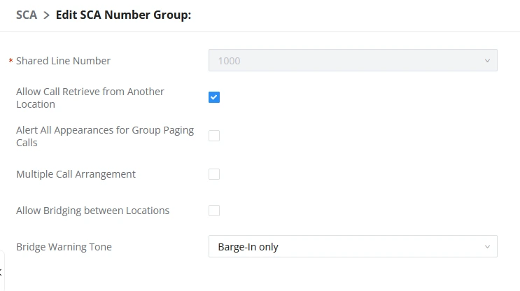
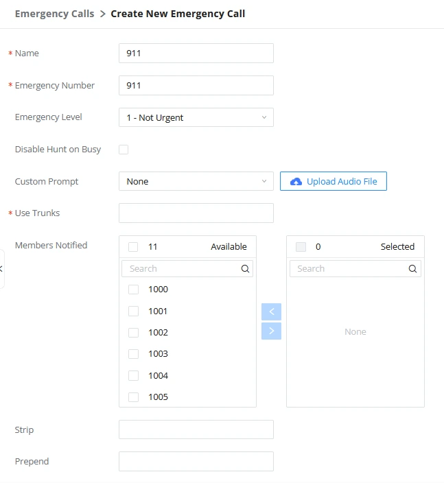

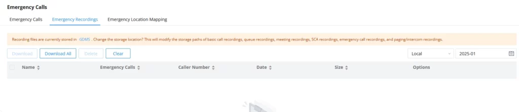
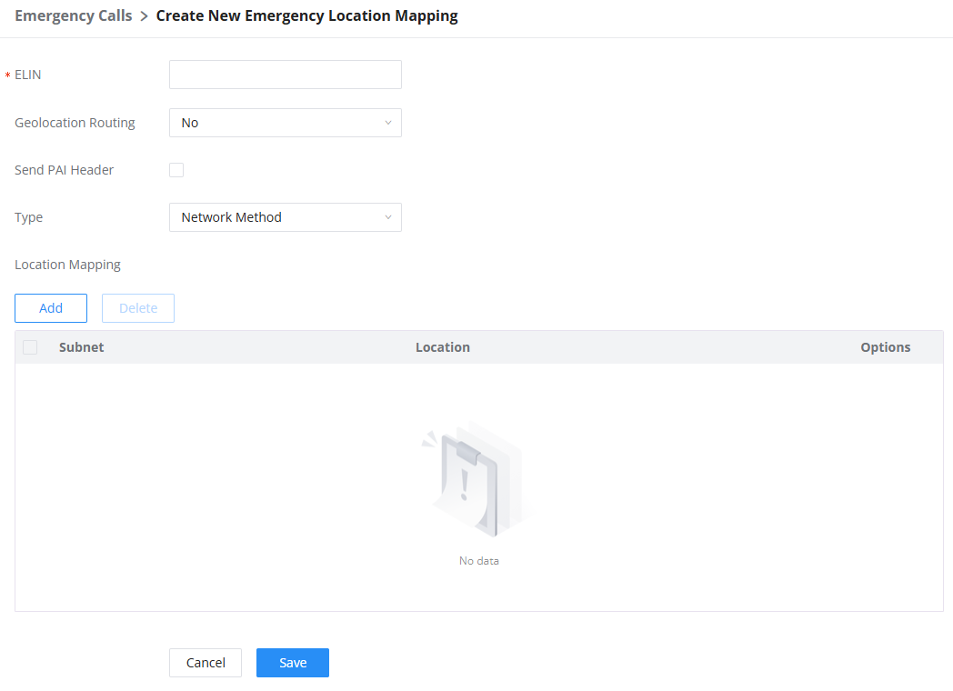
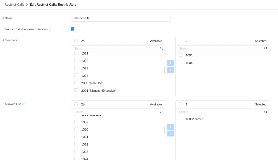
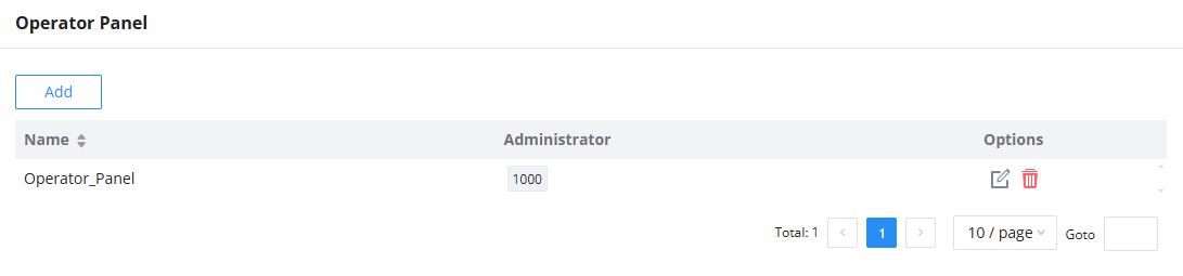


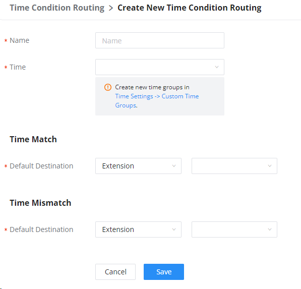
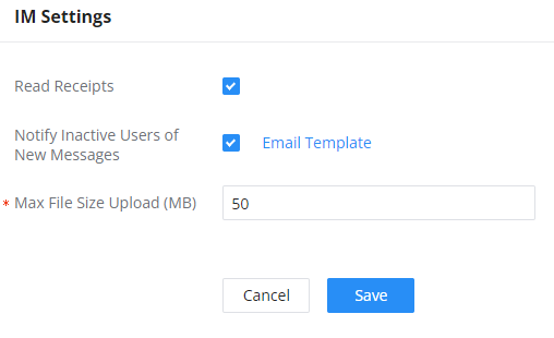
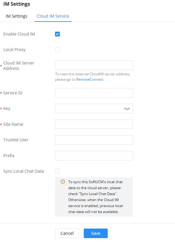

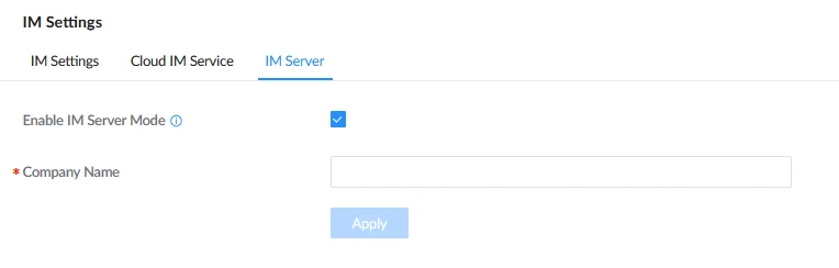
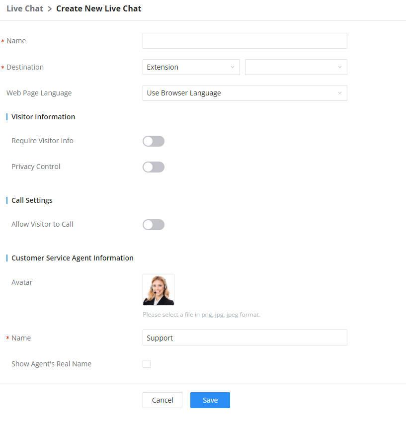
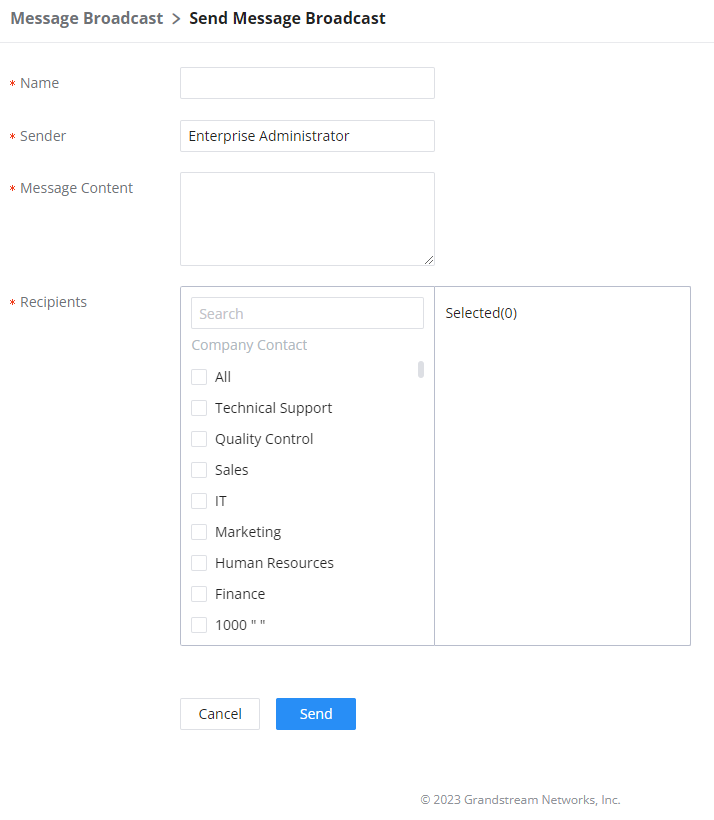
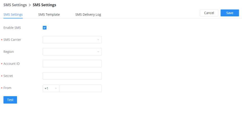
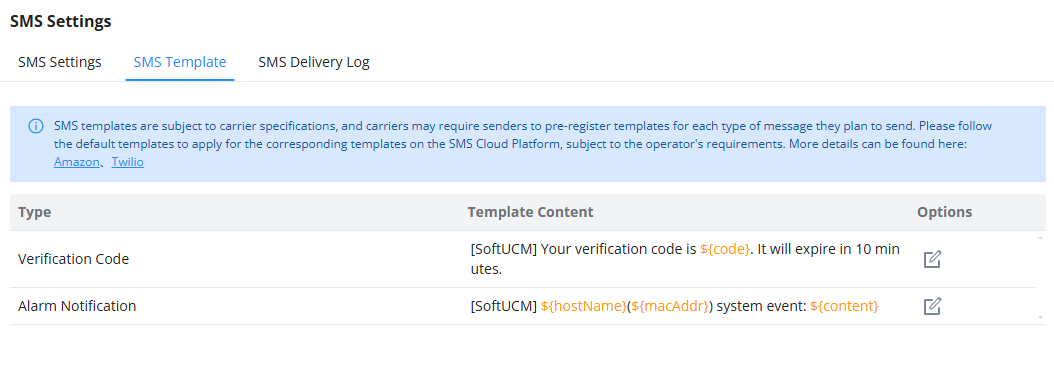
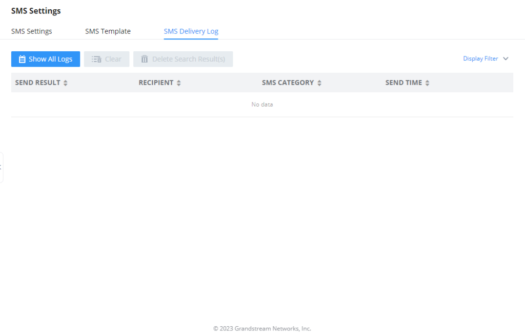
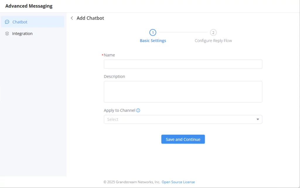
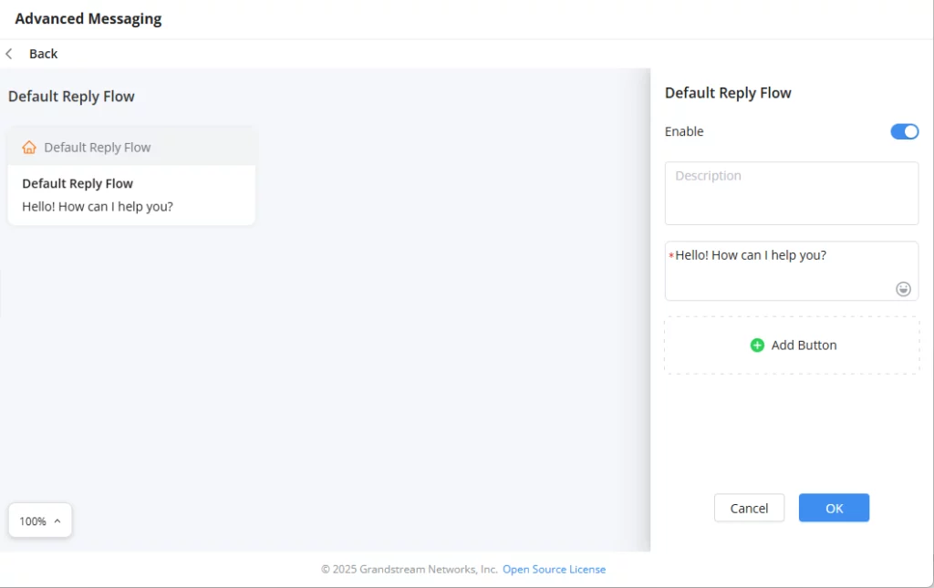
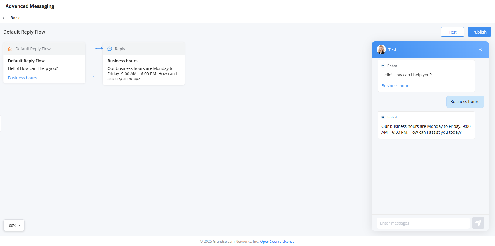
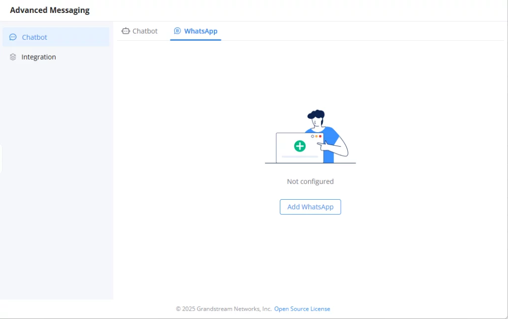
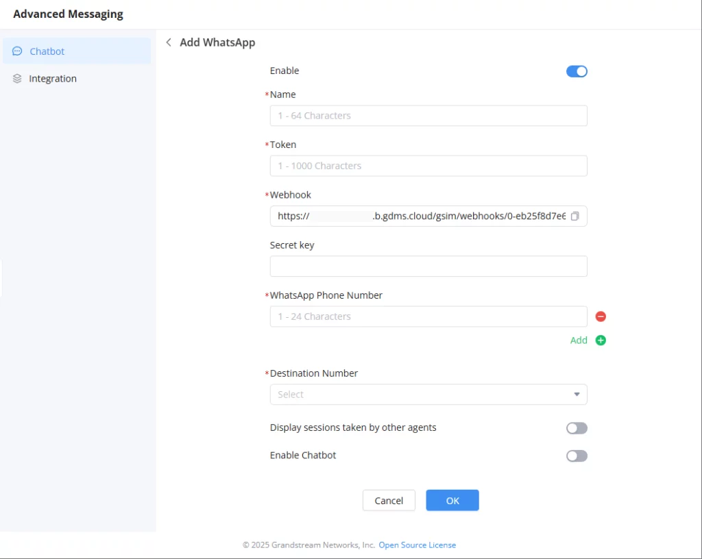
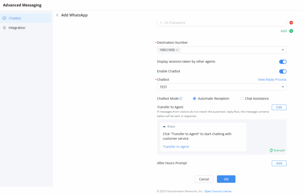
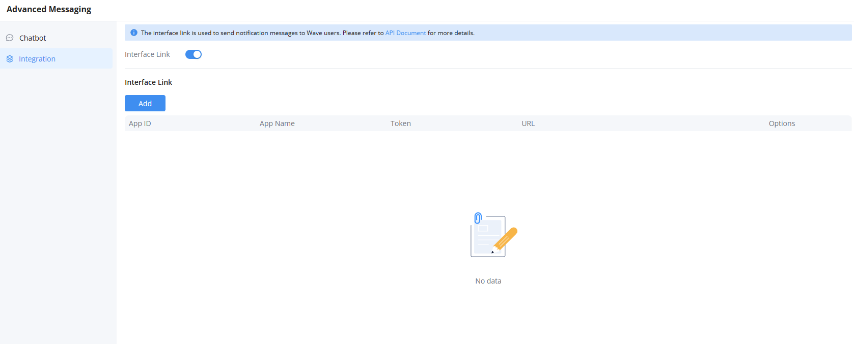
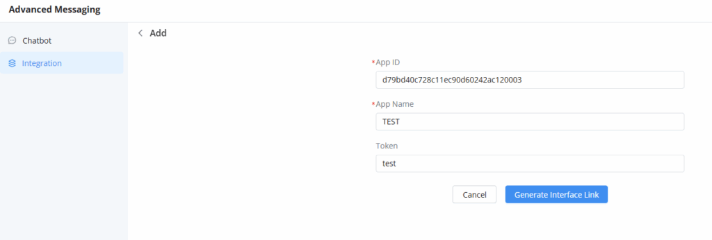
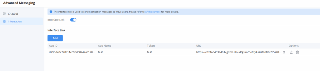


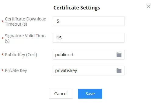
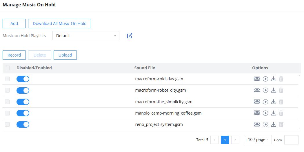


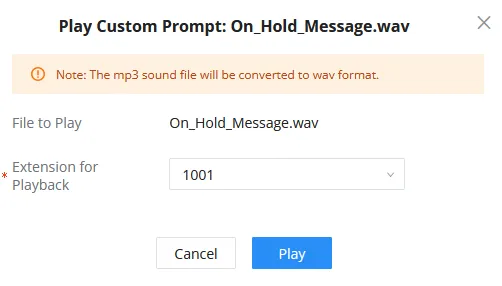




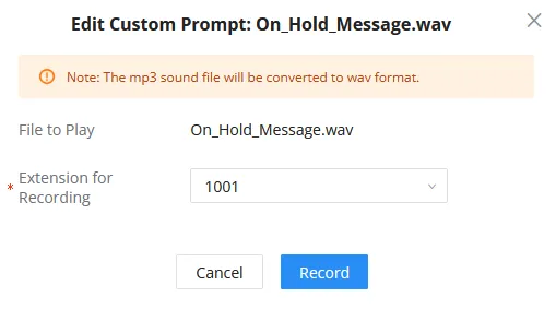
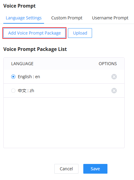
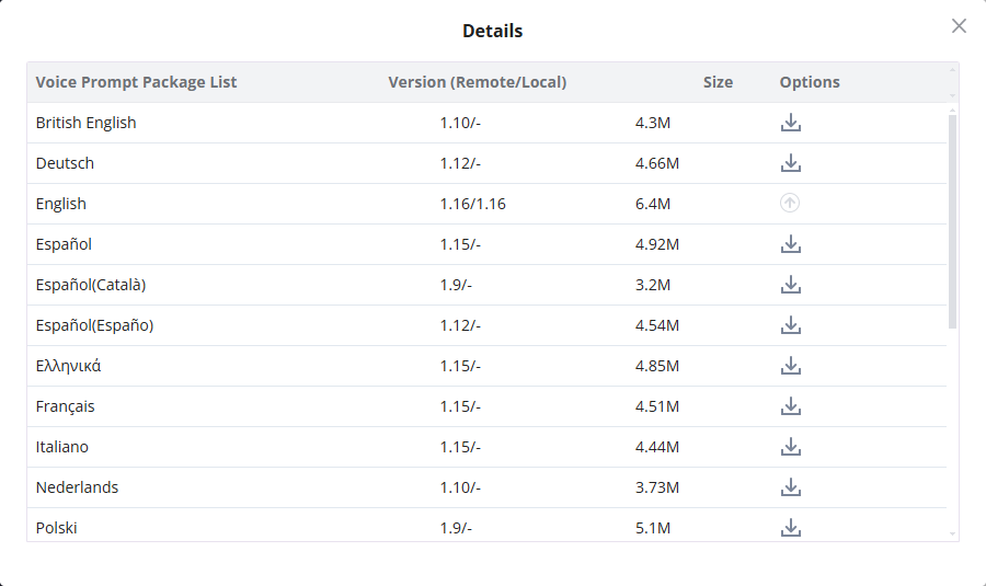
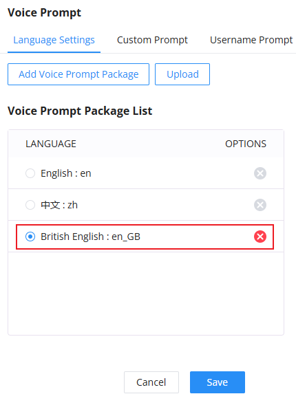
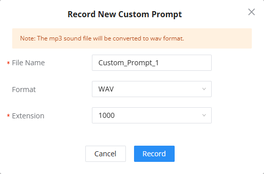

 button, select the file you want to upload, then click on “choose file to upload” to start uploading. Once uploaded, the file will appear in the Custom Prompt web page.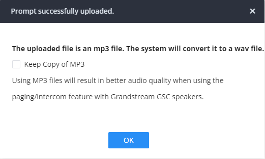
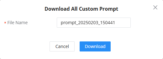


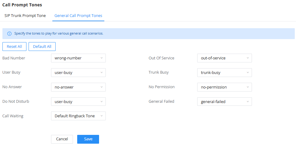
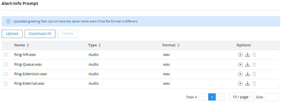
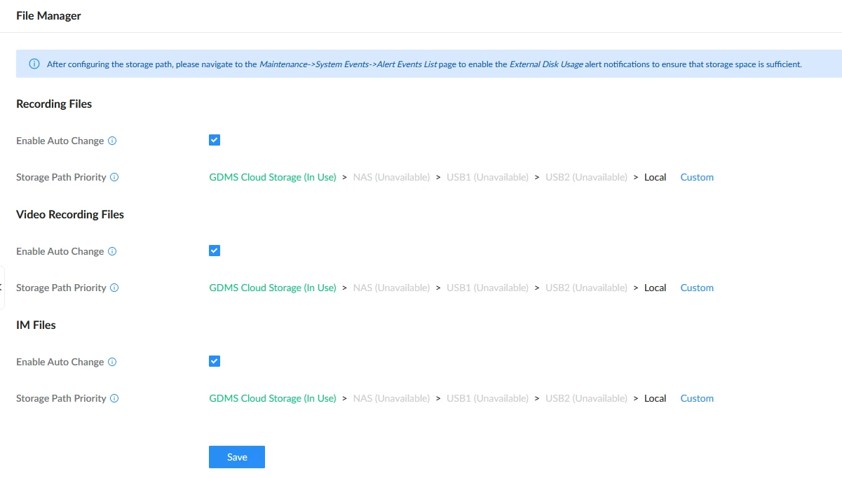


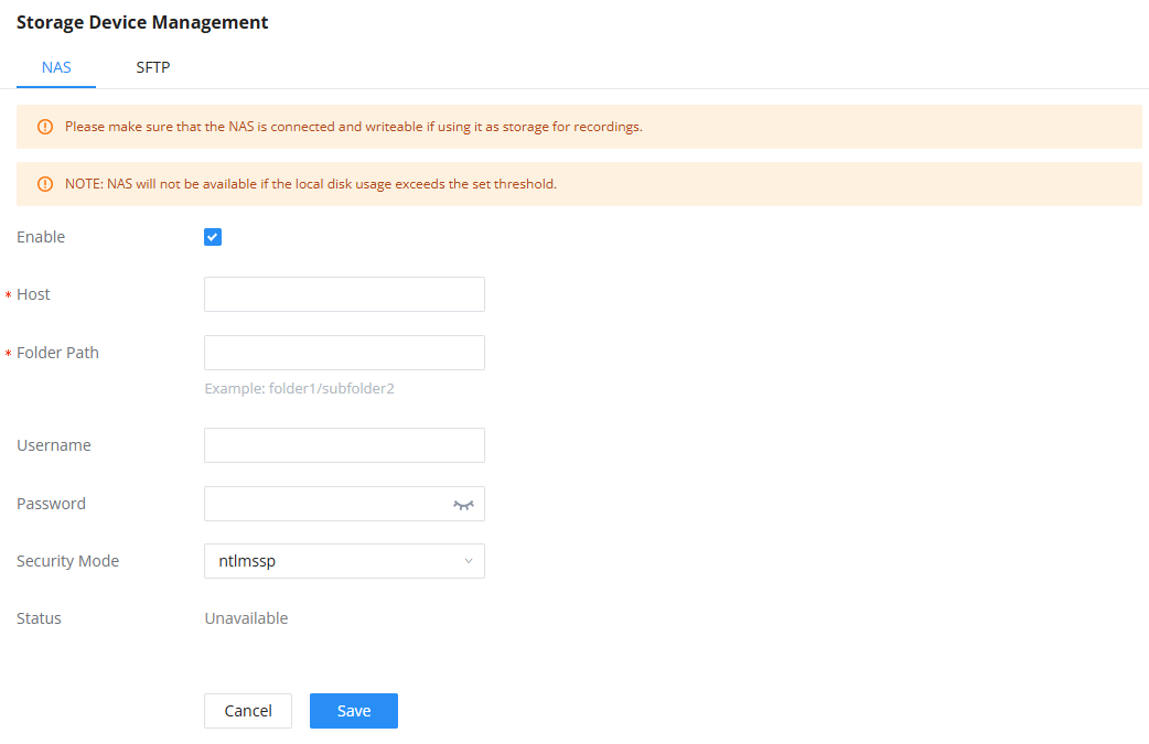
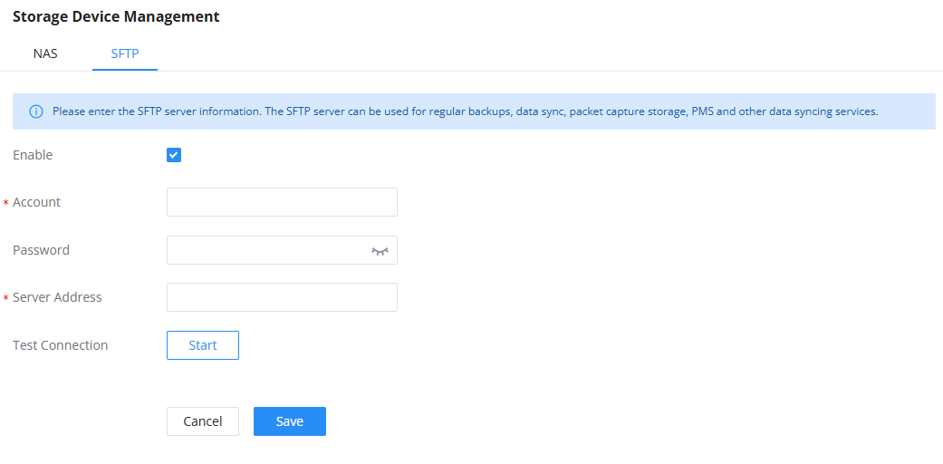
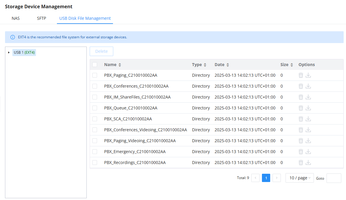
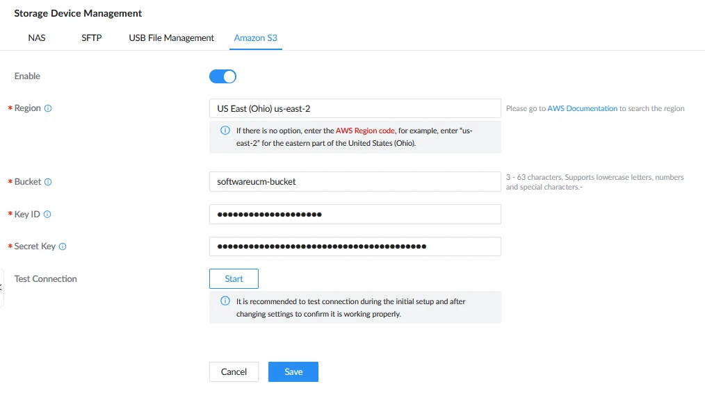
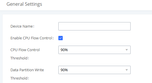
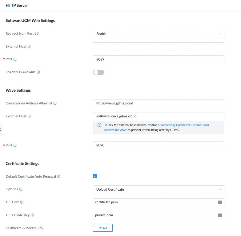
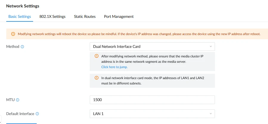
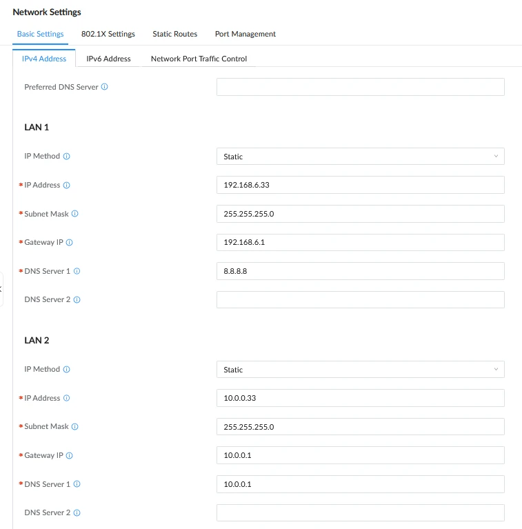
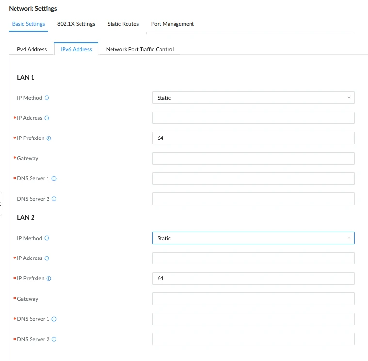
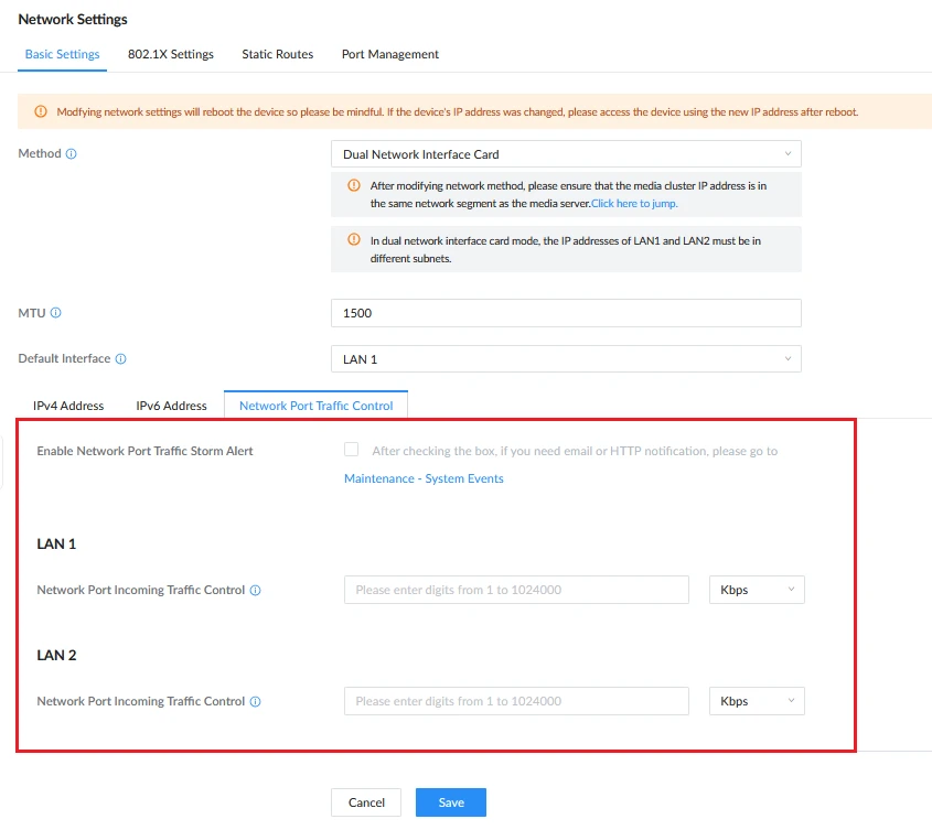
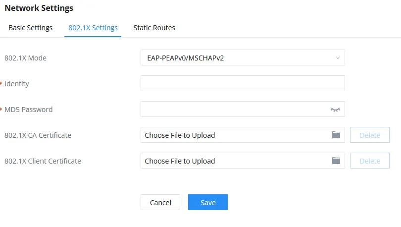


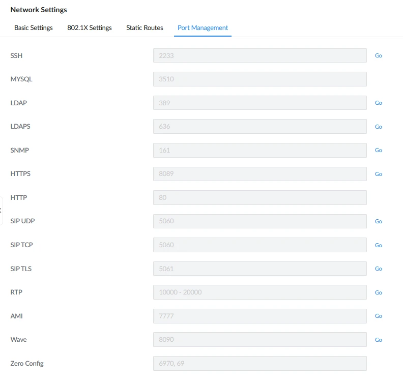
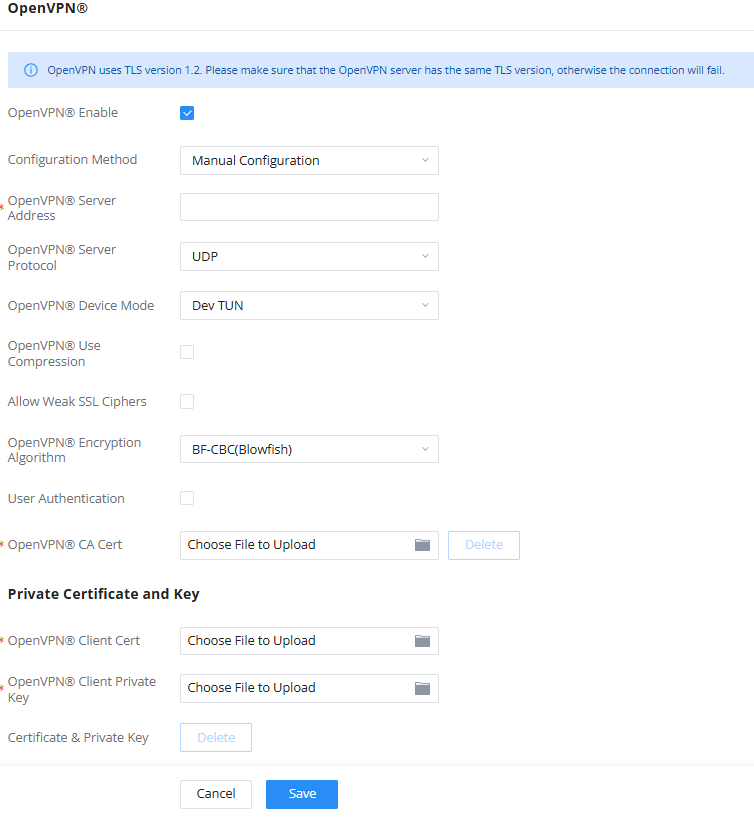
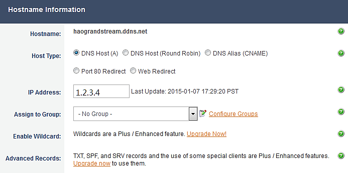
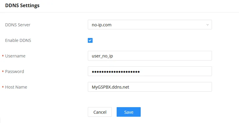
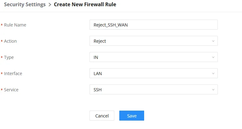


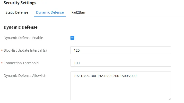
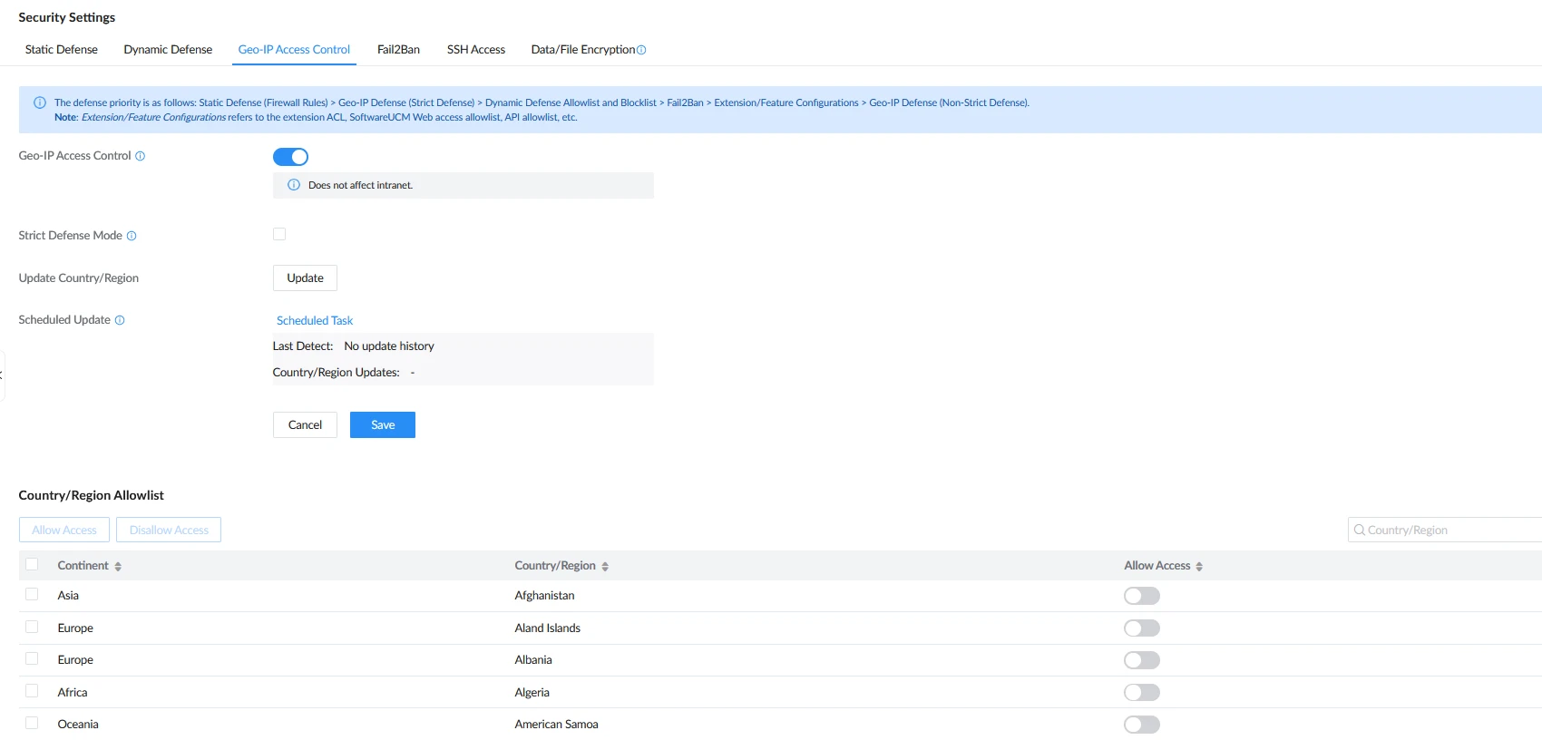
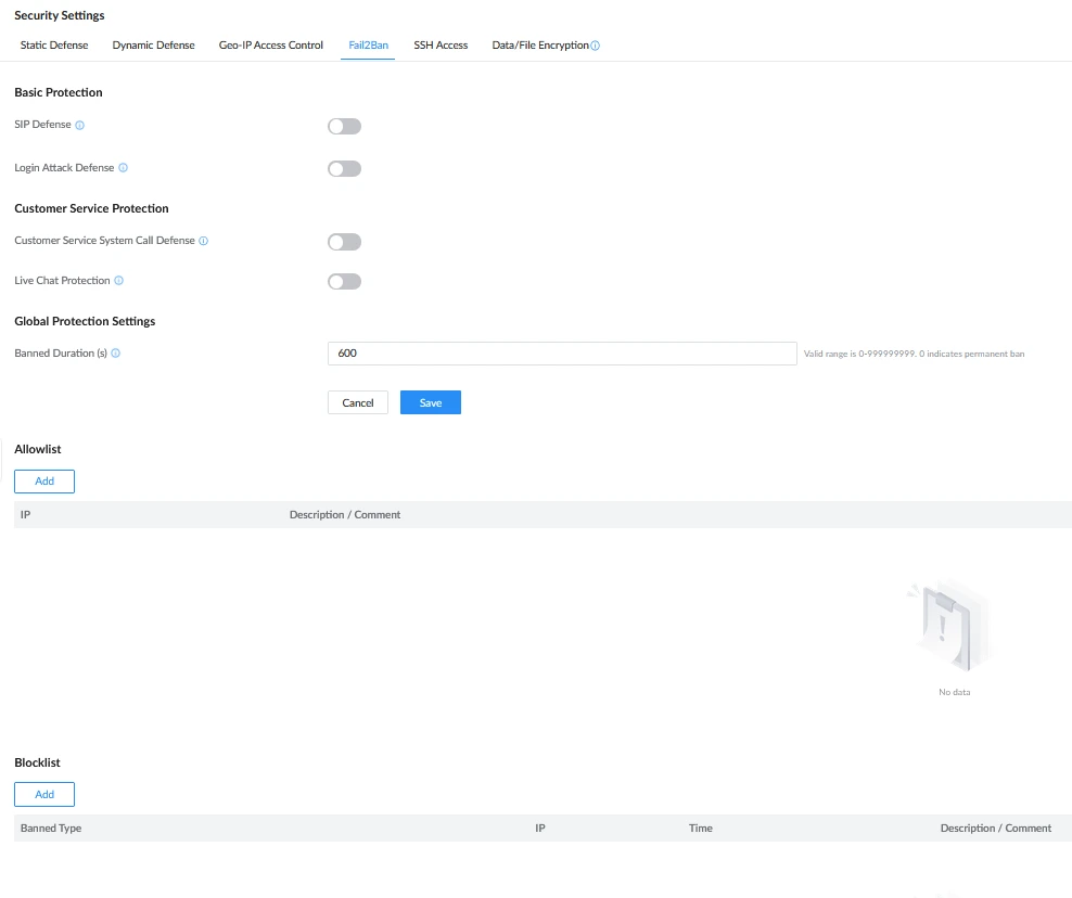
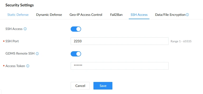
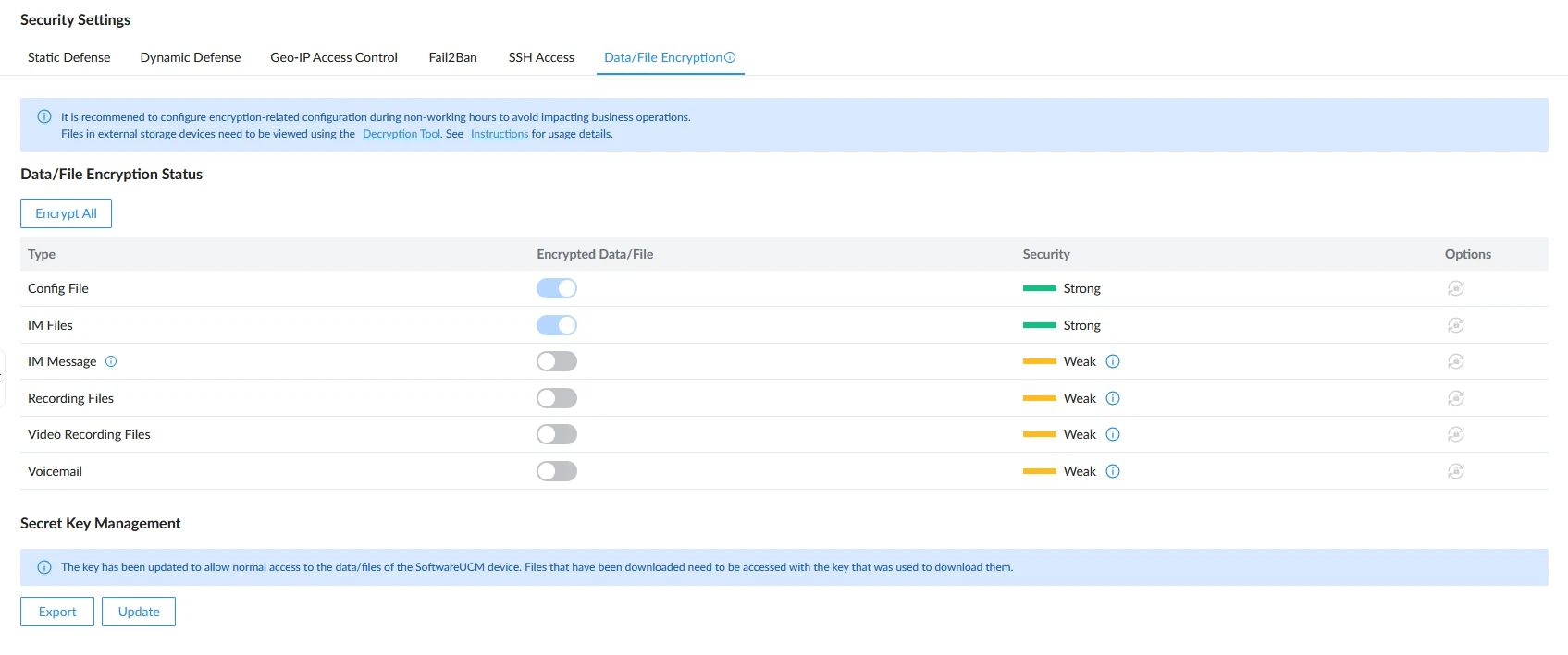
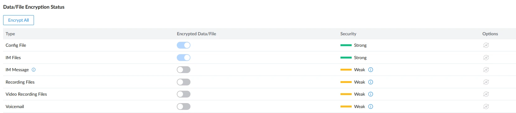
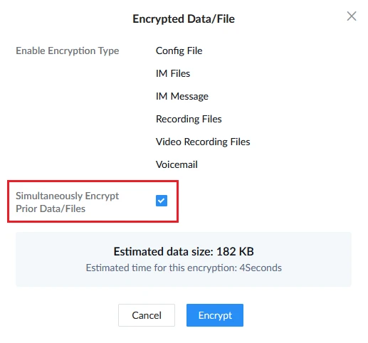

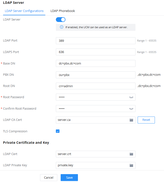
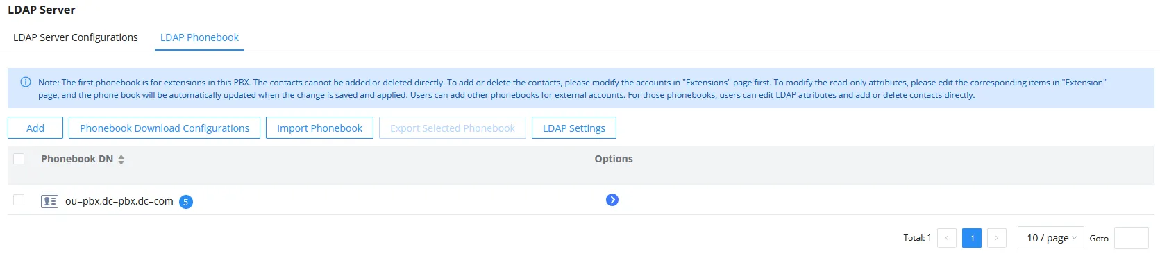
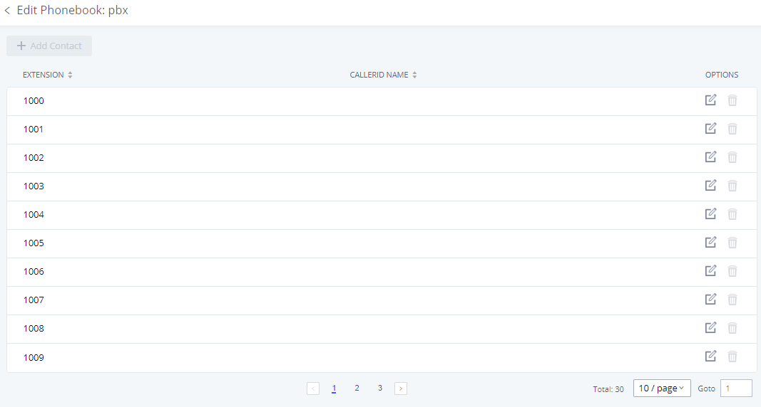
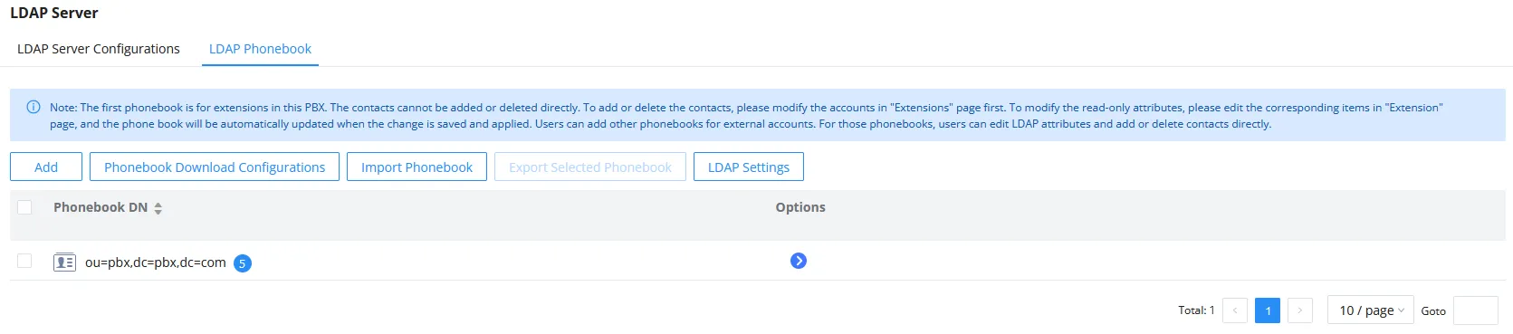
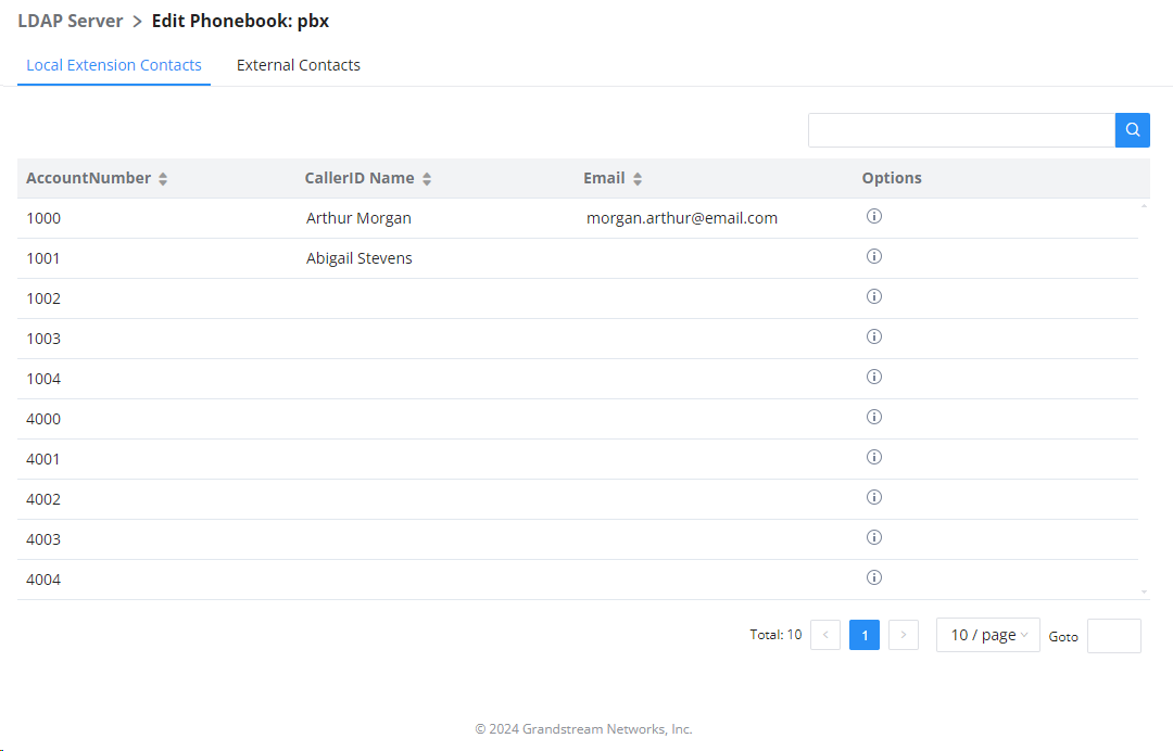
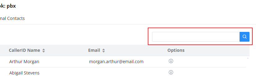
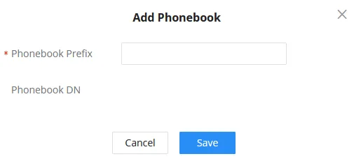
 to edit the phonebook attributes and contact list (see figure below) or select
  to delete the phonebook.
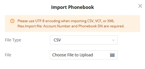

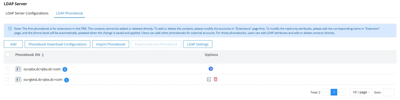
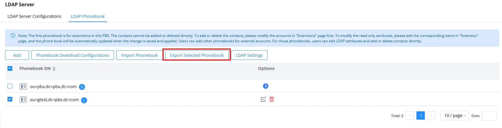
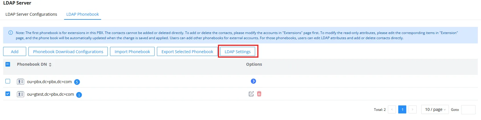
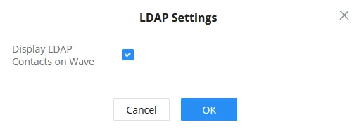
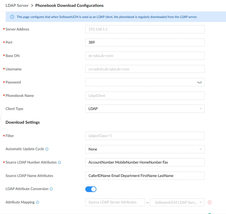
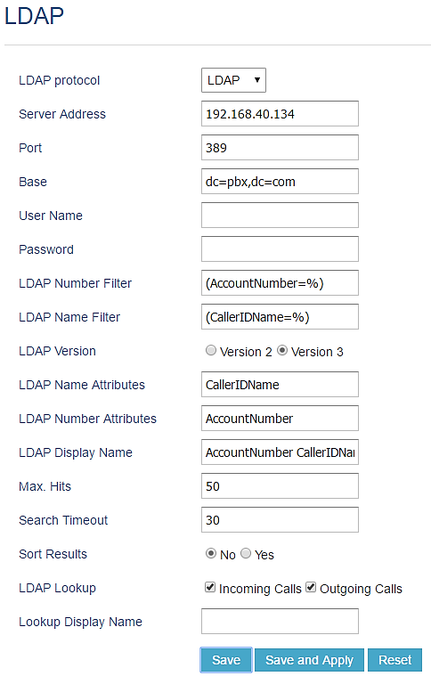
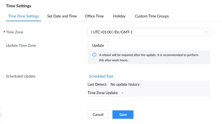
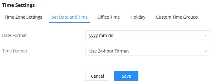
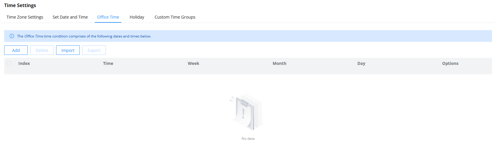
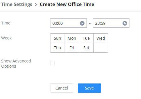
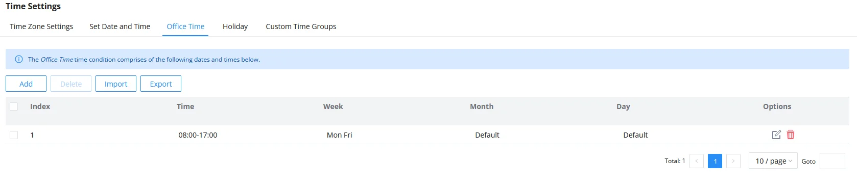



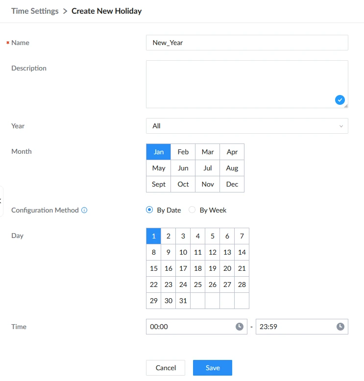
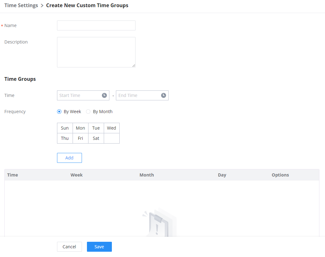
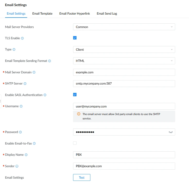
 icon to edit the template.
 icon to edit the template.

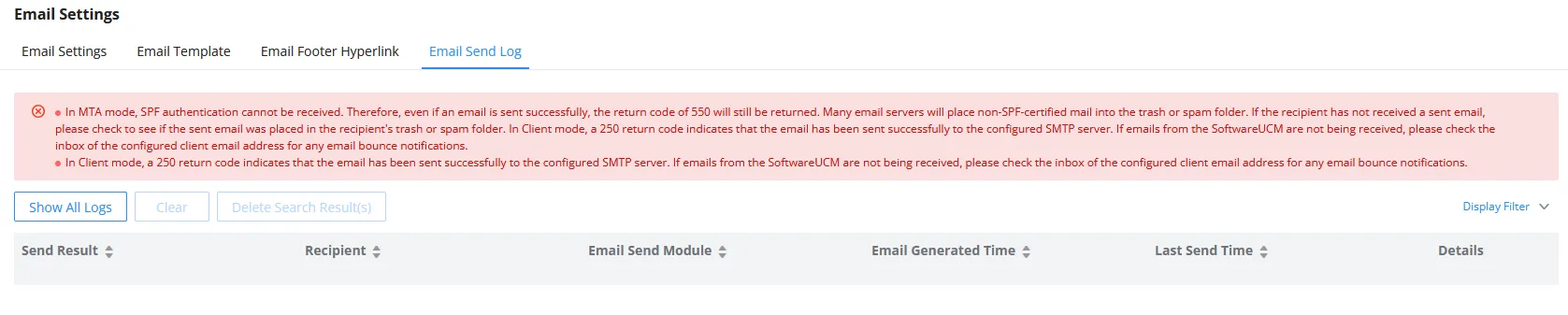
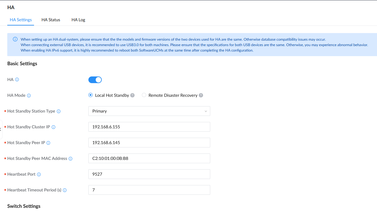
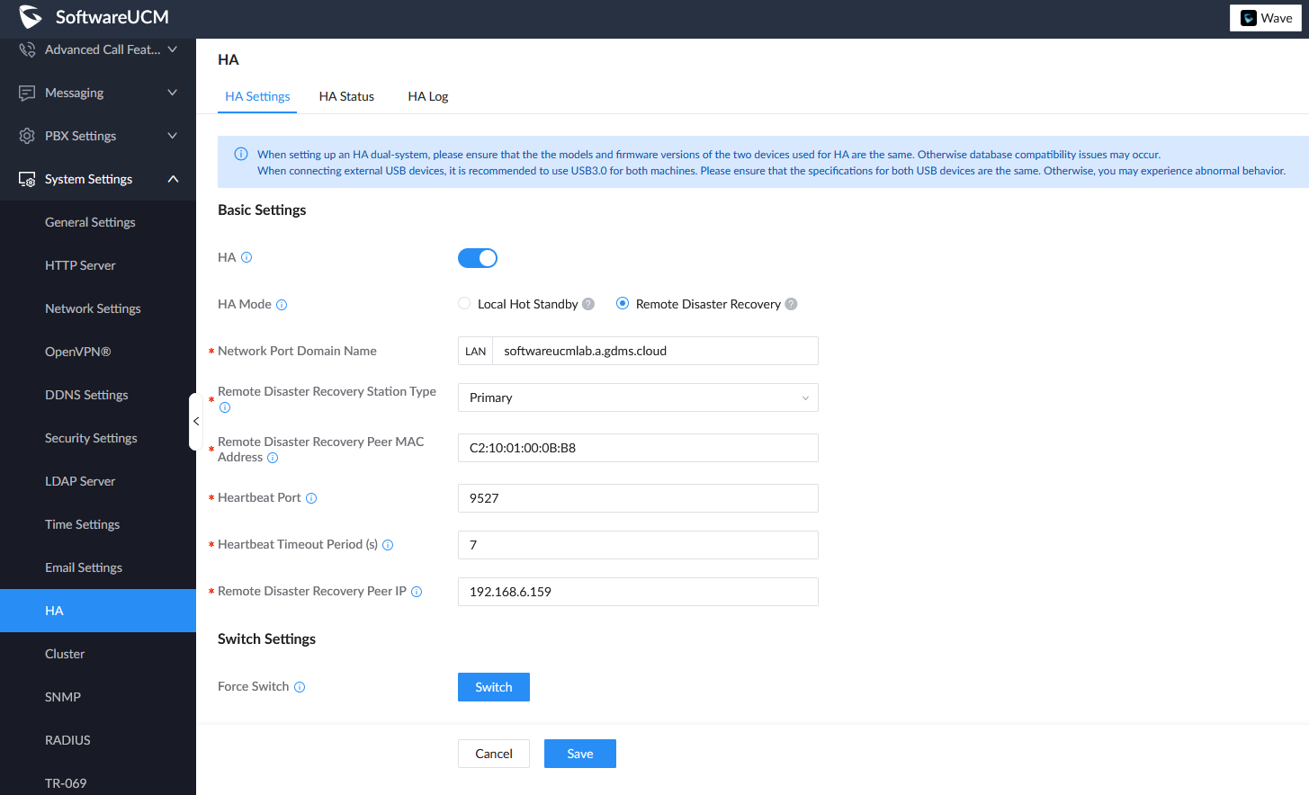
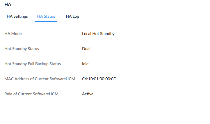
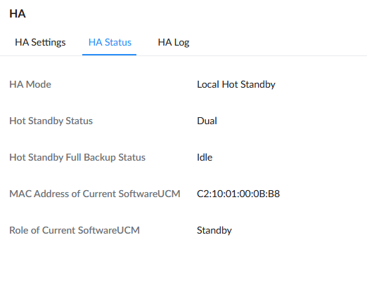
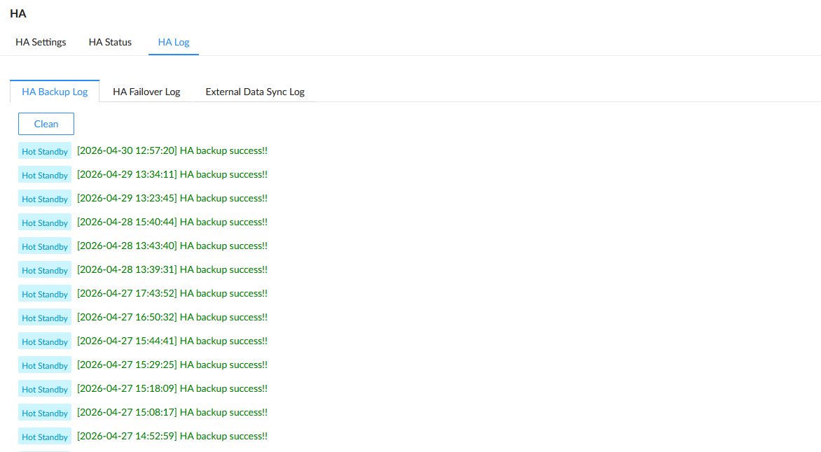
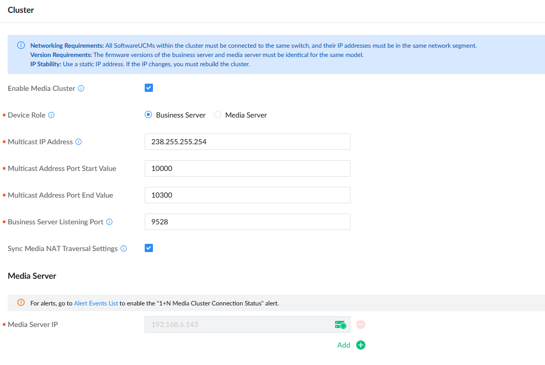
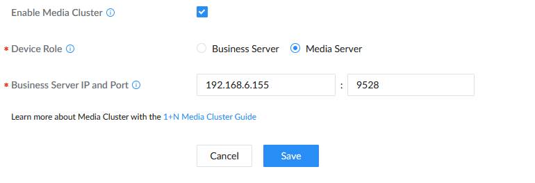
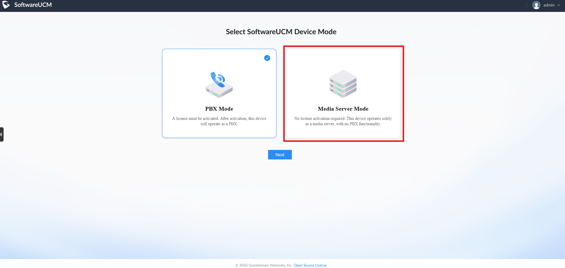
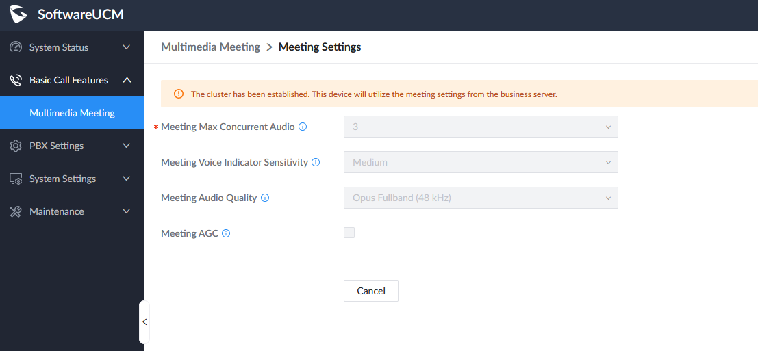
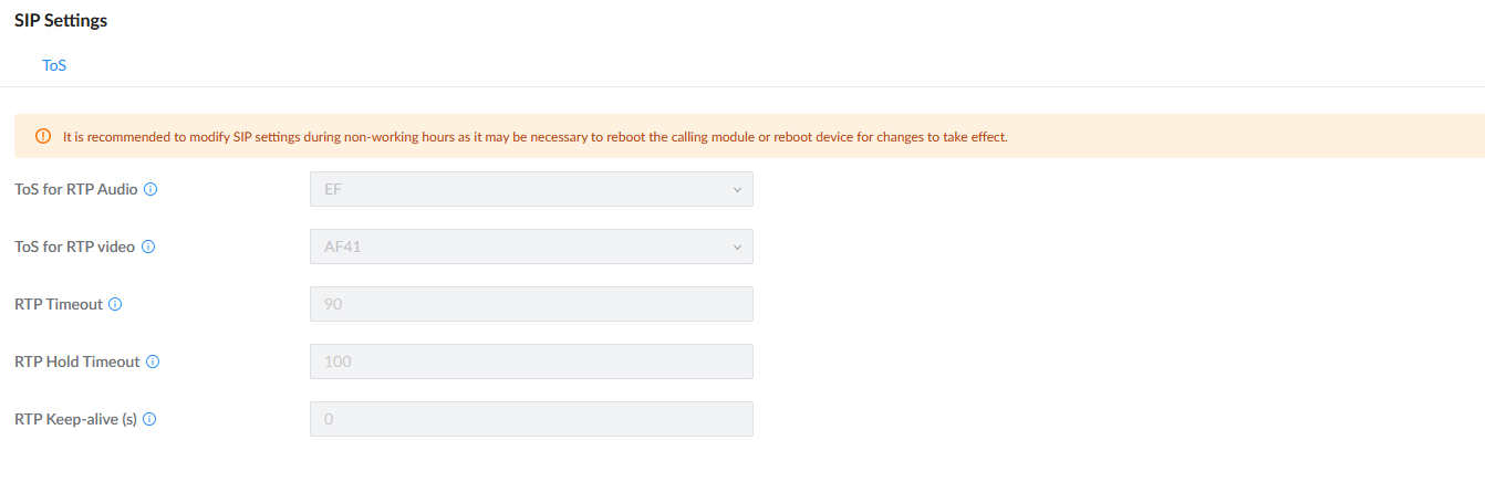

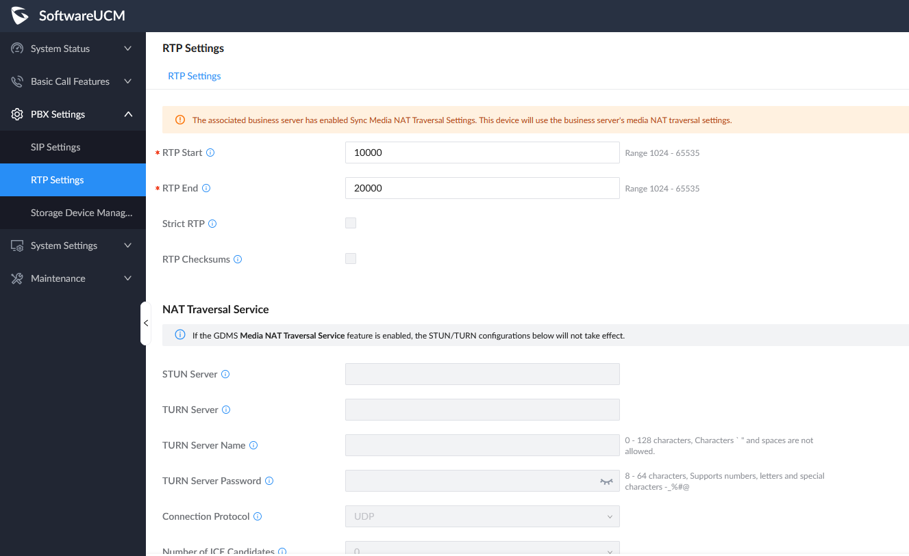
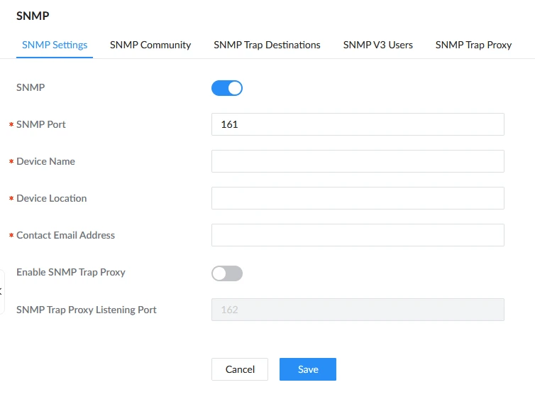
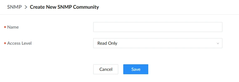
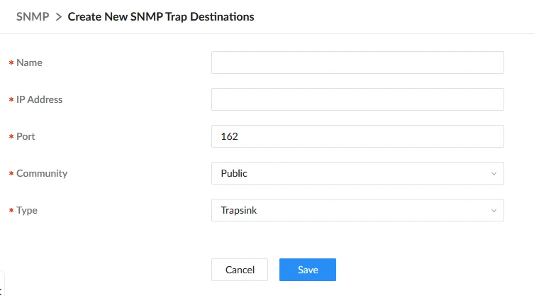
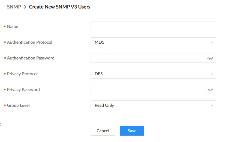
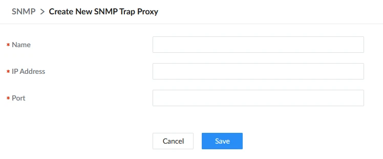
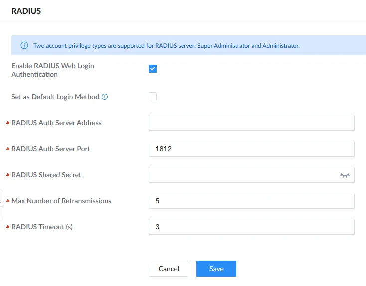

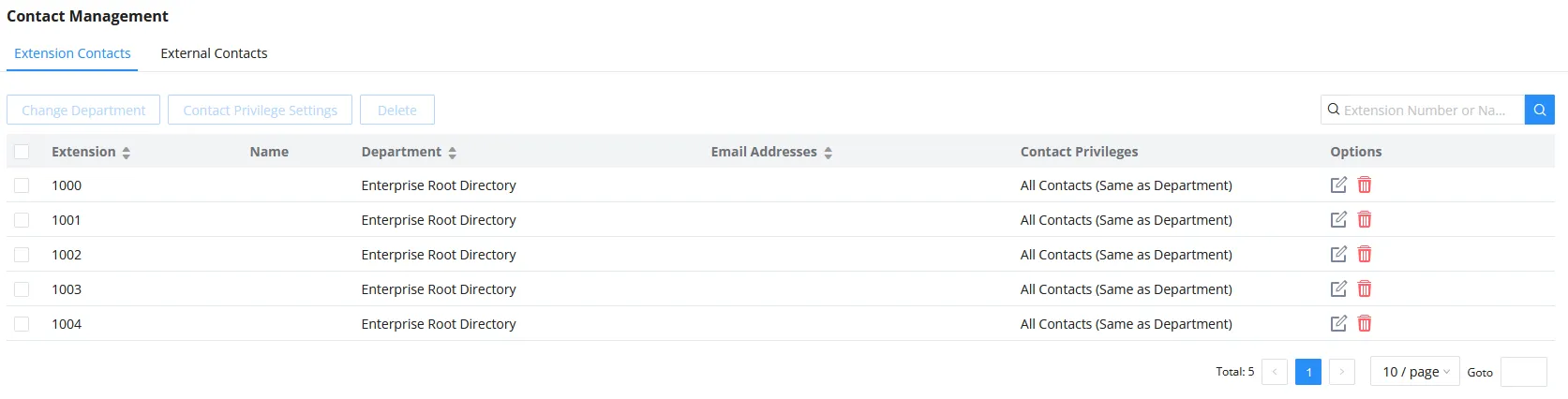
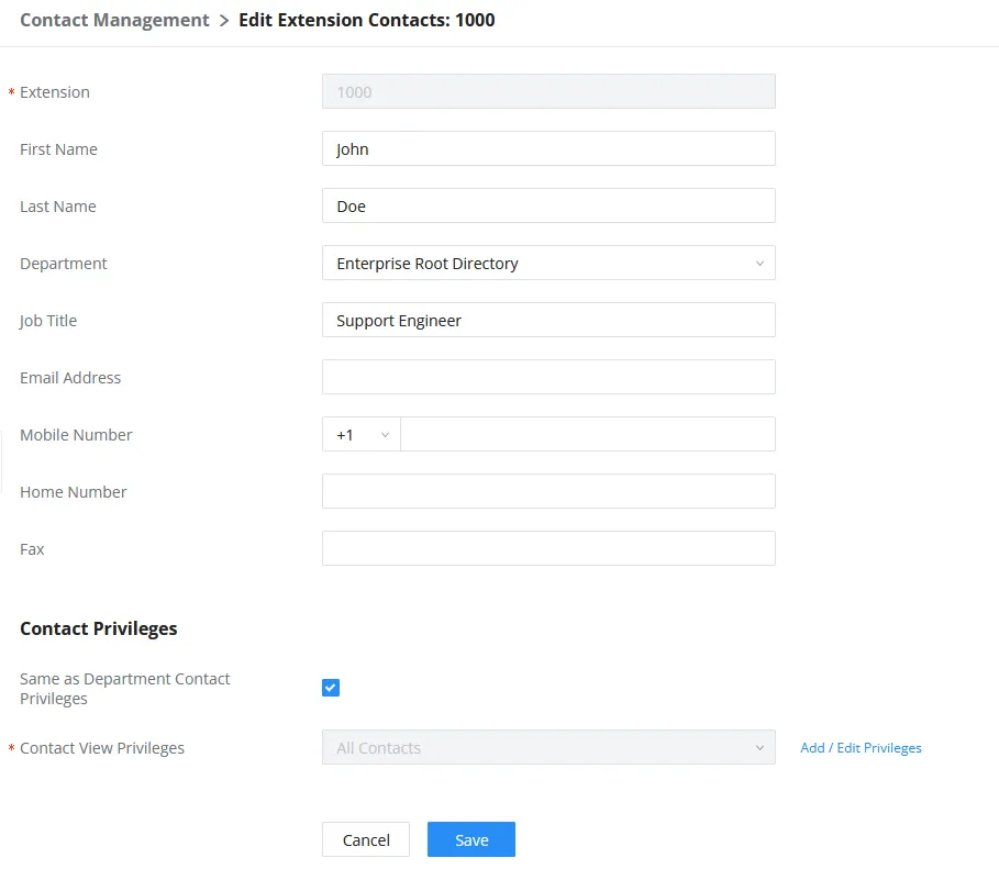

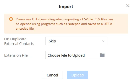



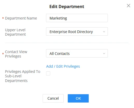

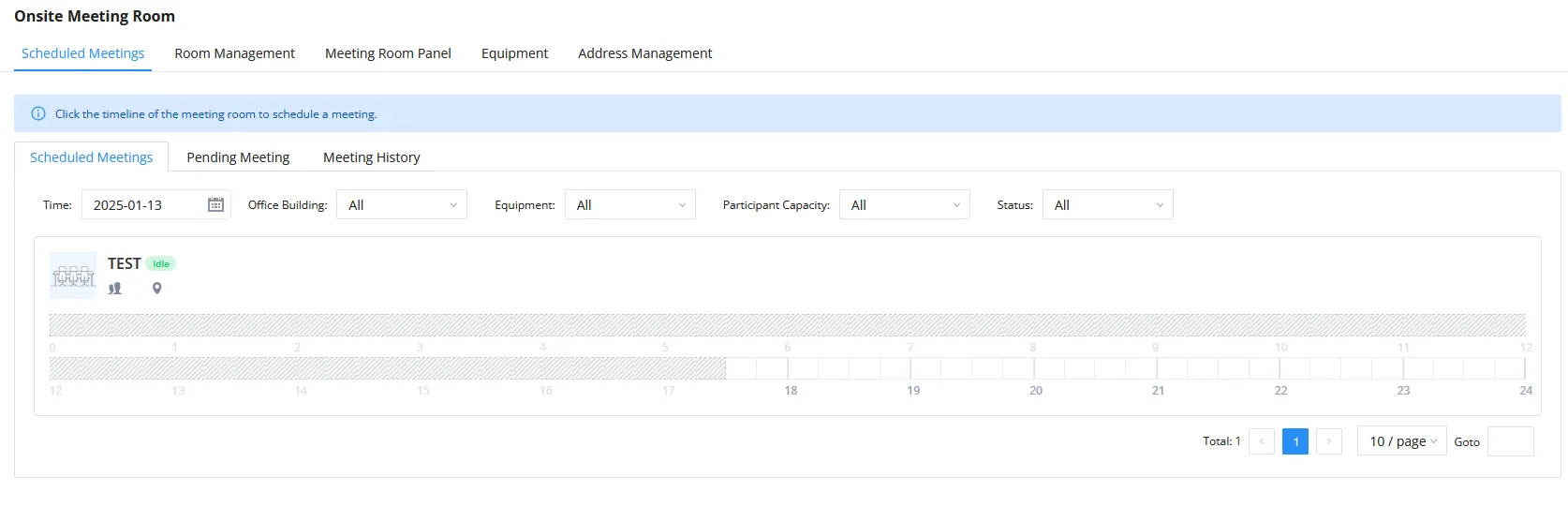
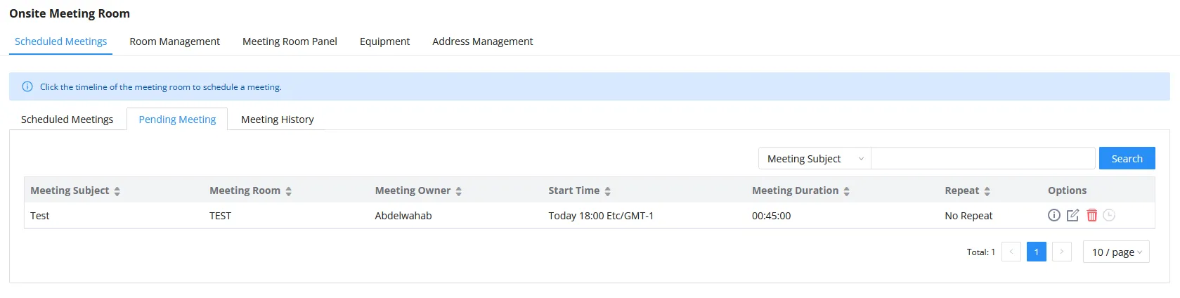

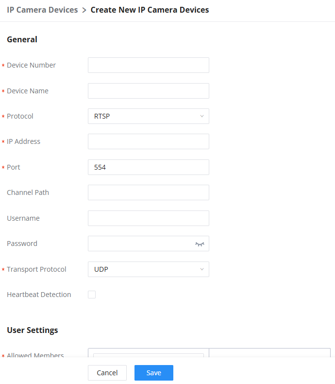
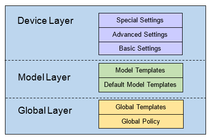
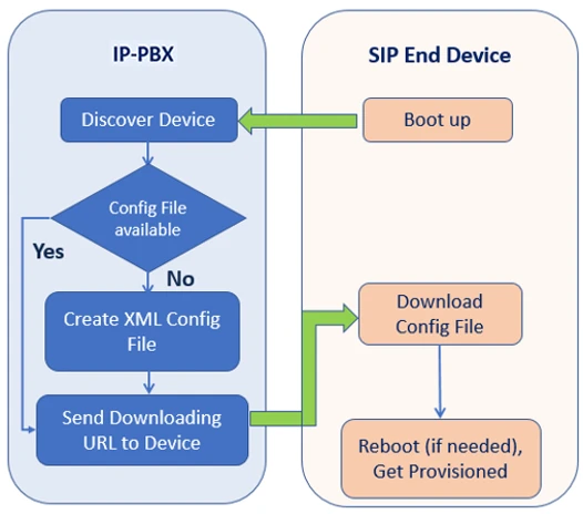
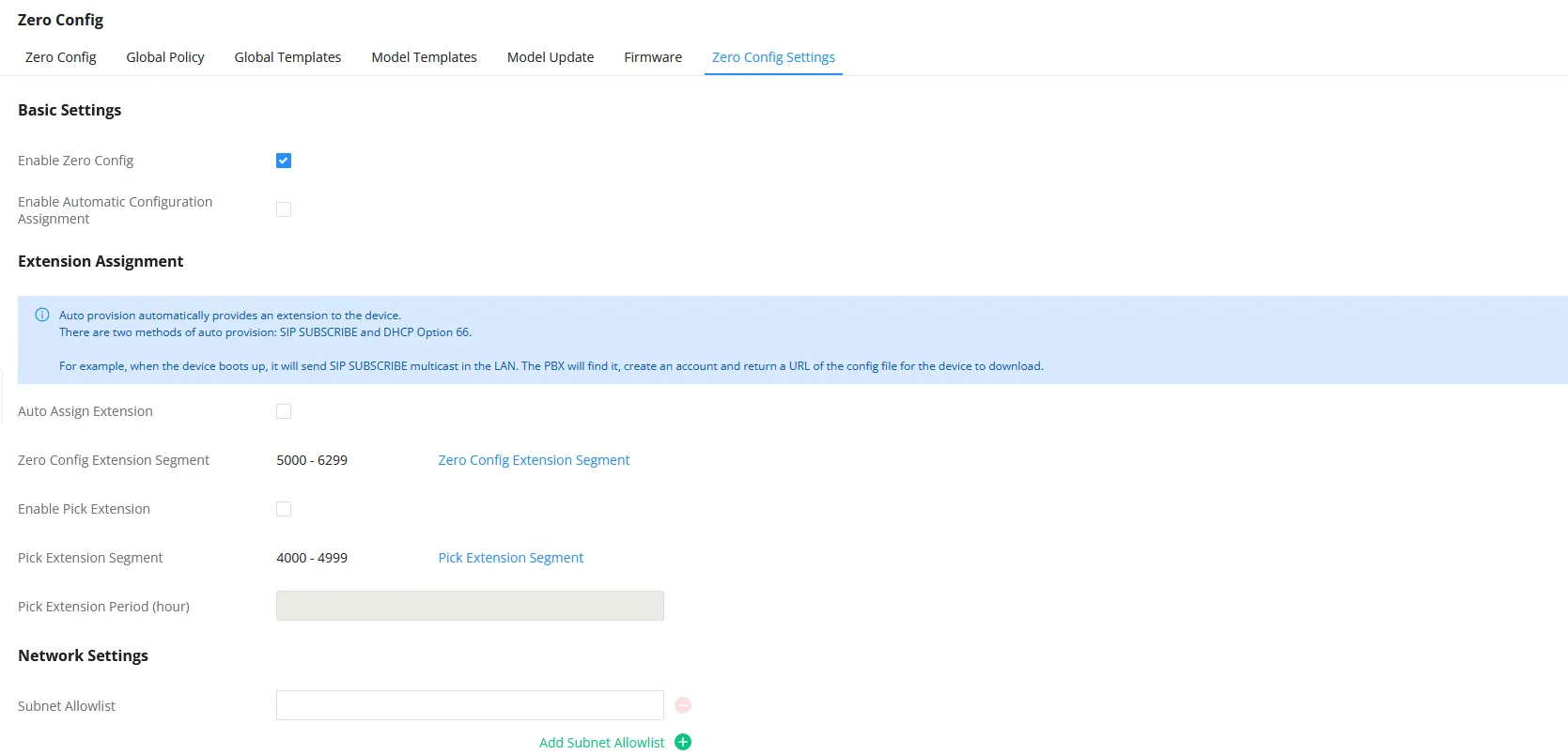

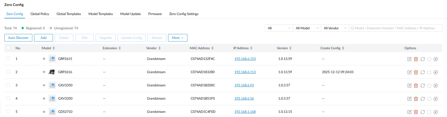
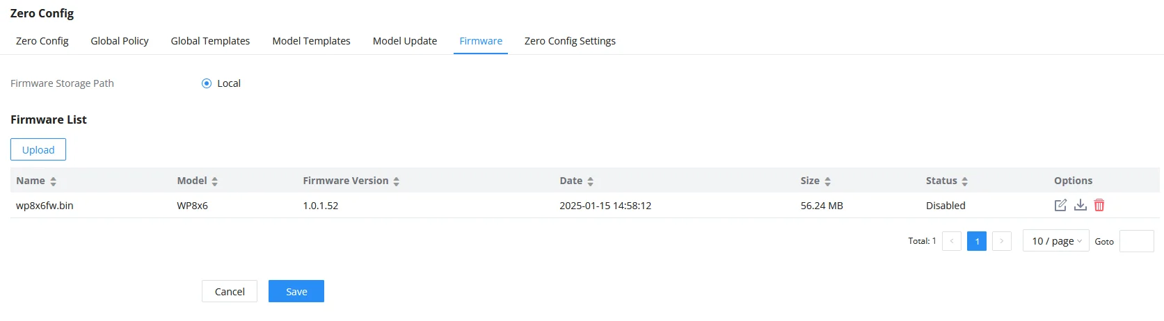
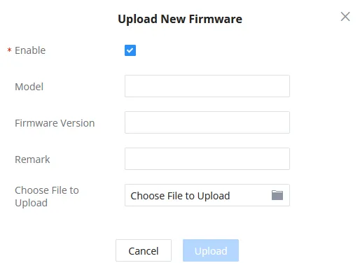
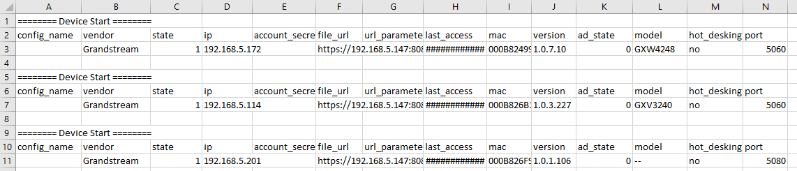
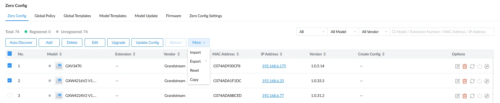
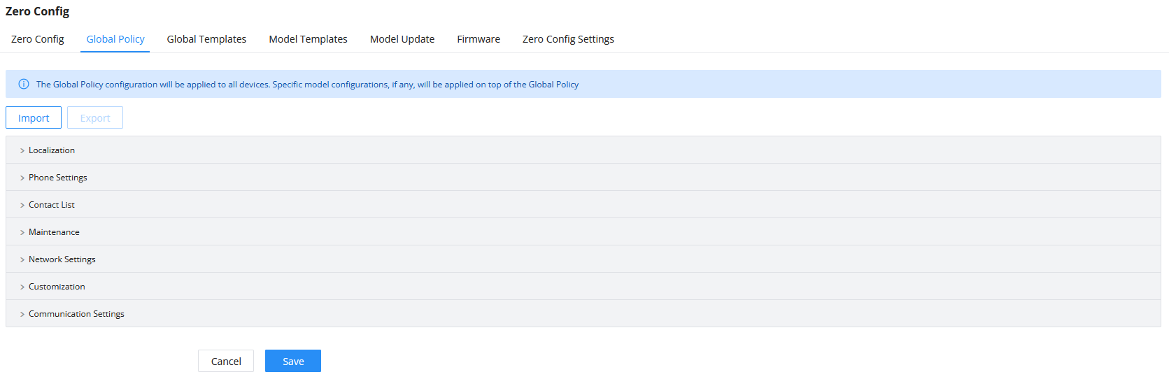
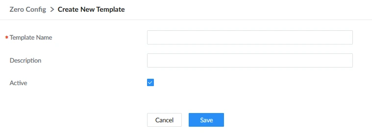
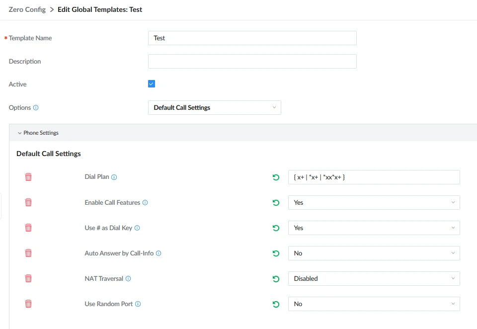
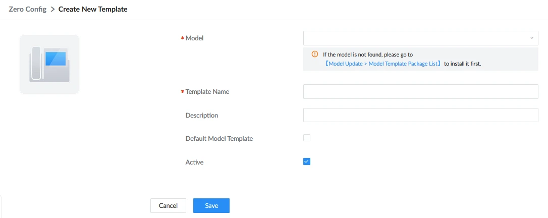



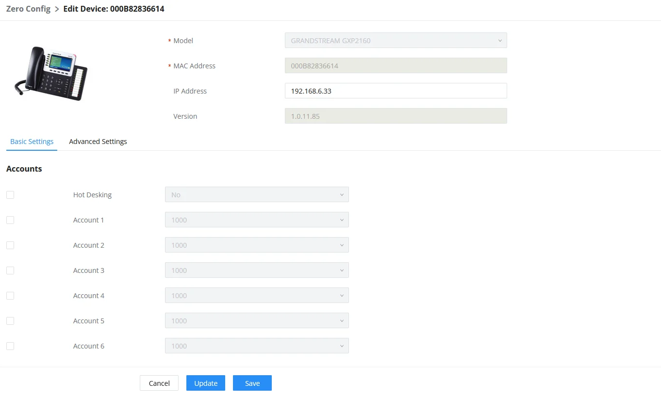
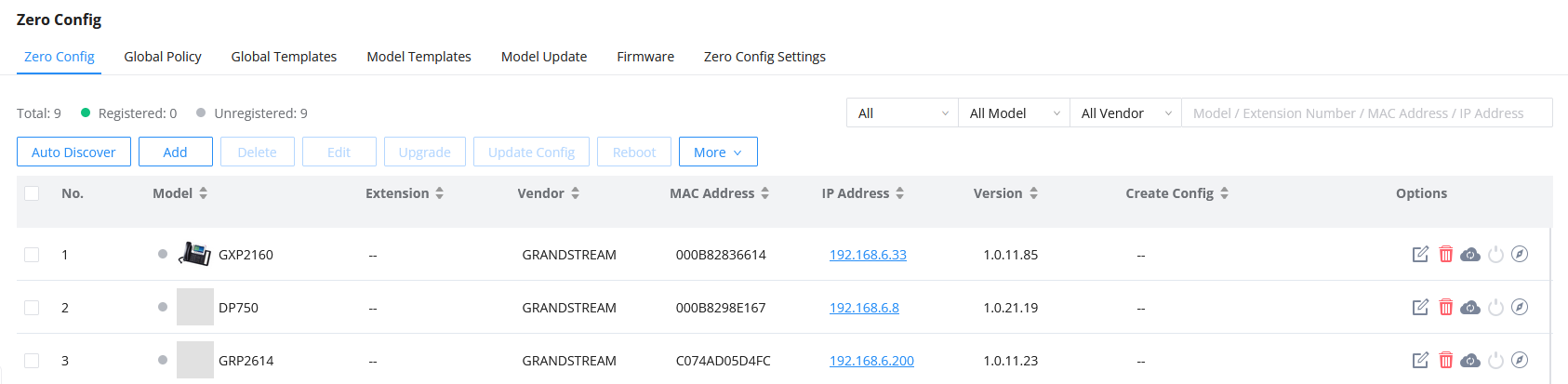
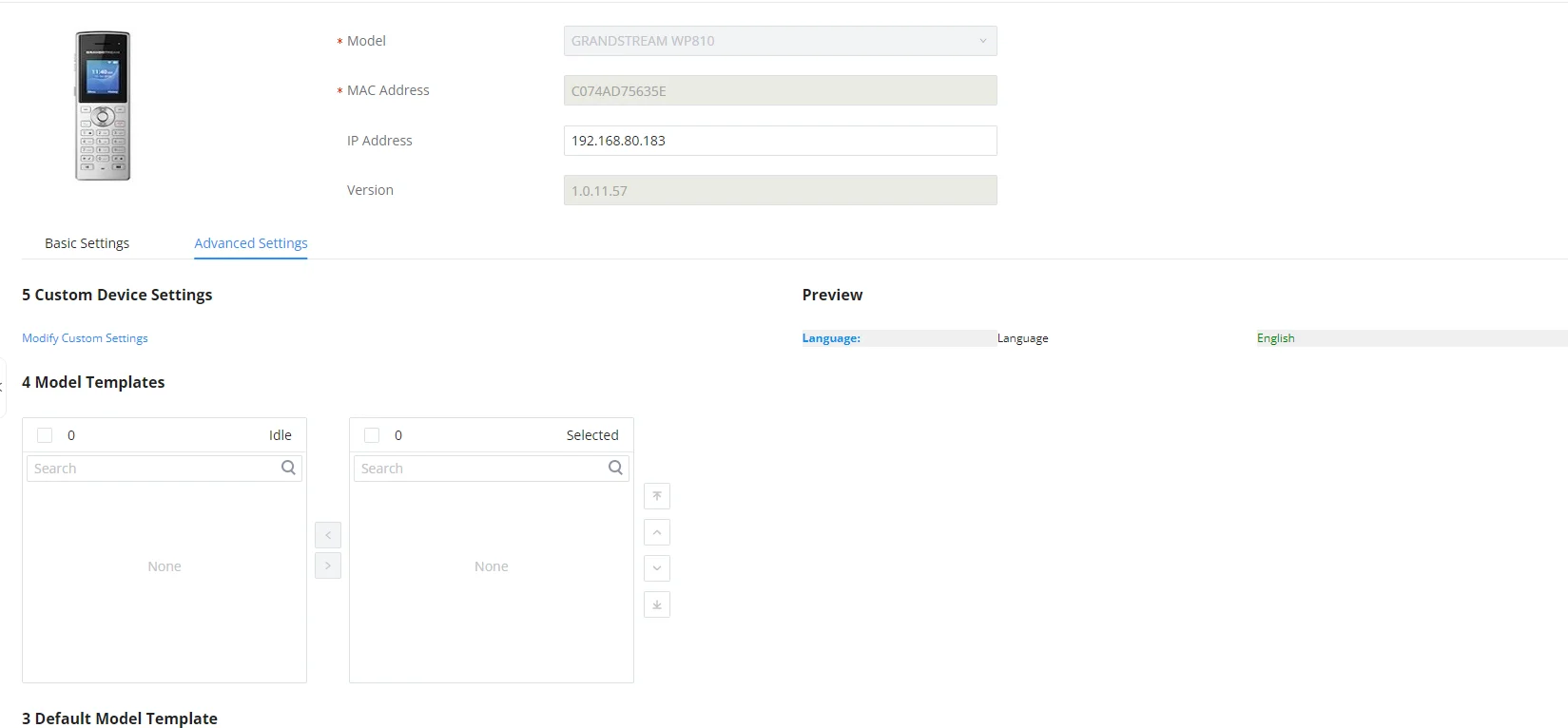
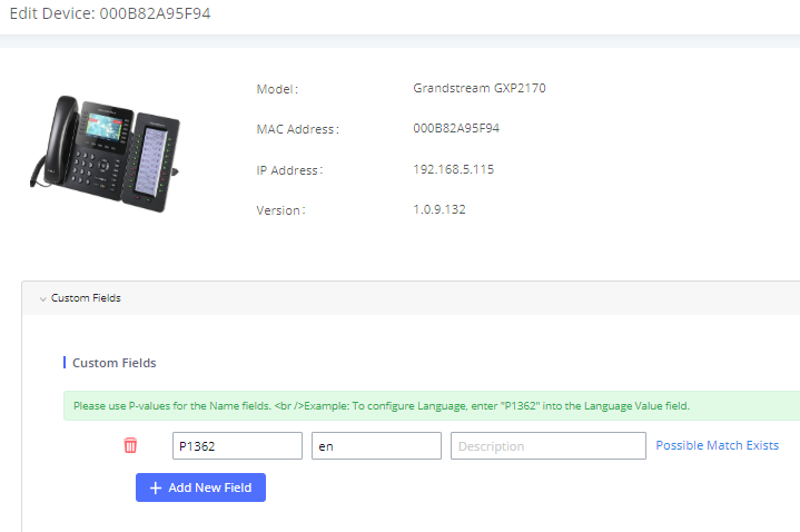
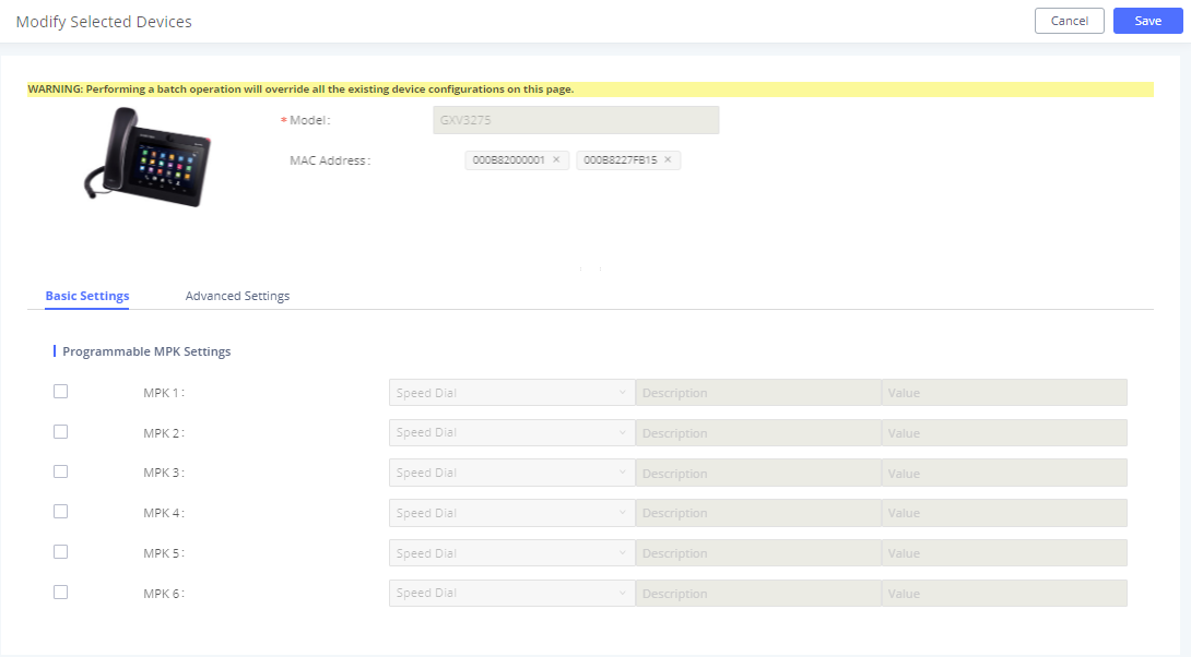
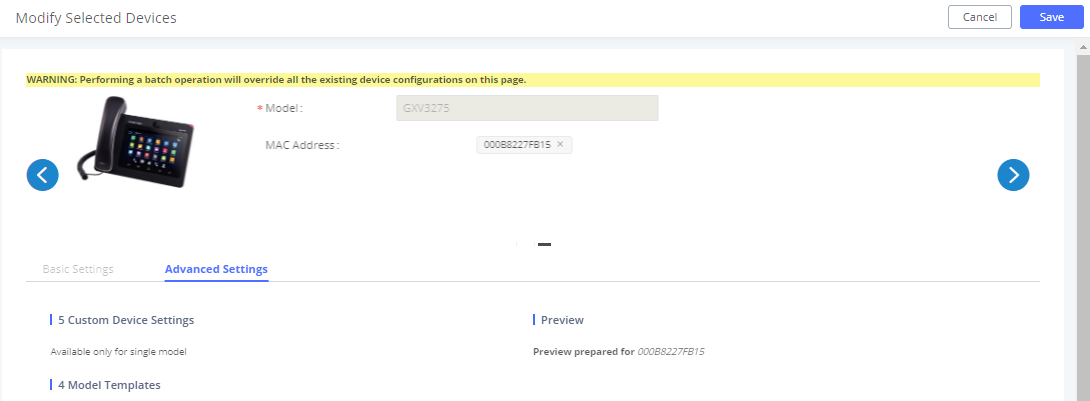
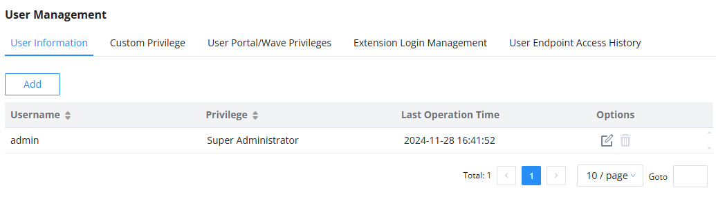
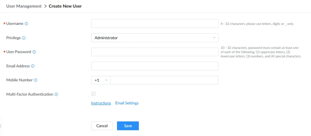
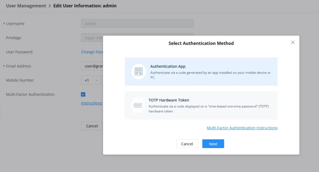
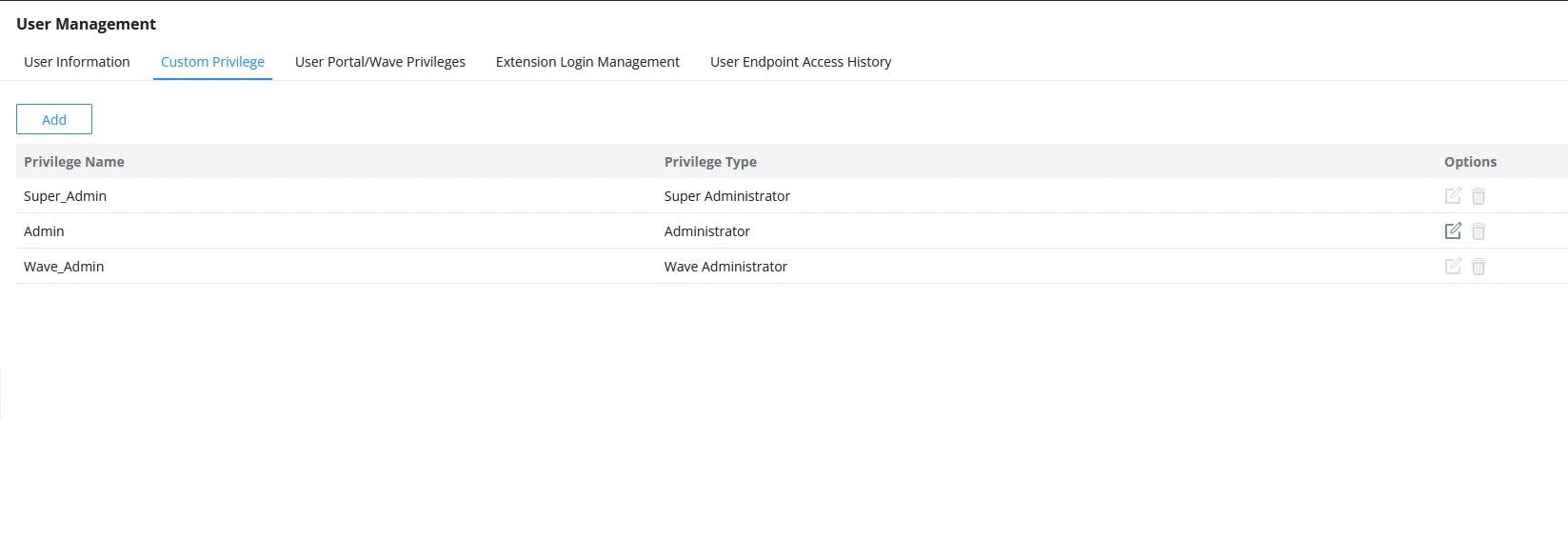

 to edit the “Admin” account and include backup operation permission for these types of users.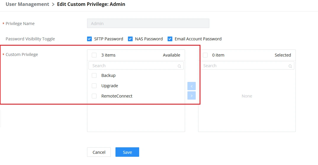
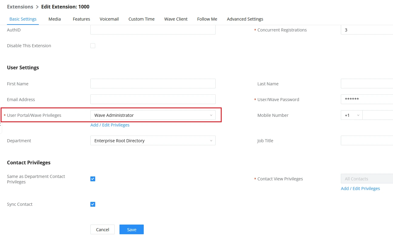
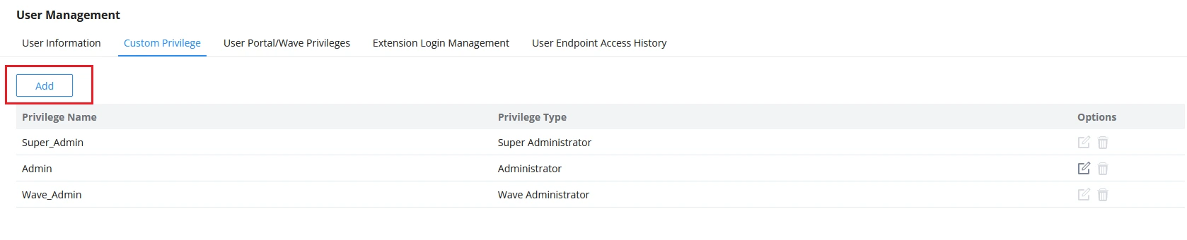
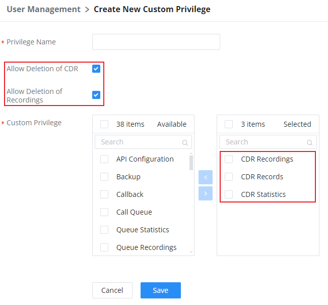

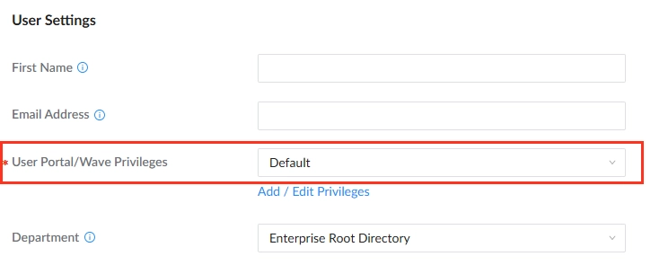
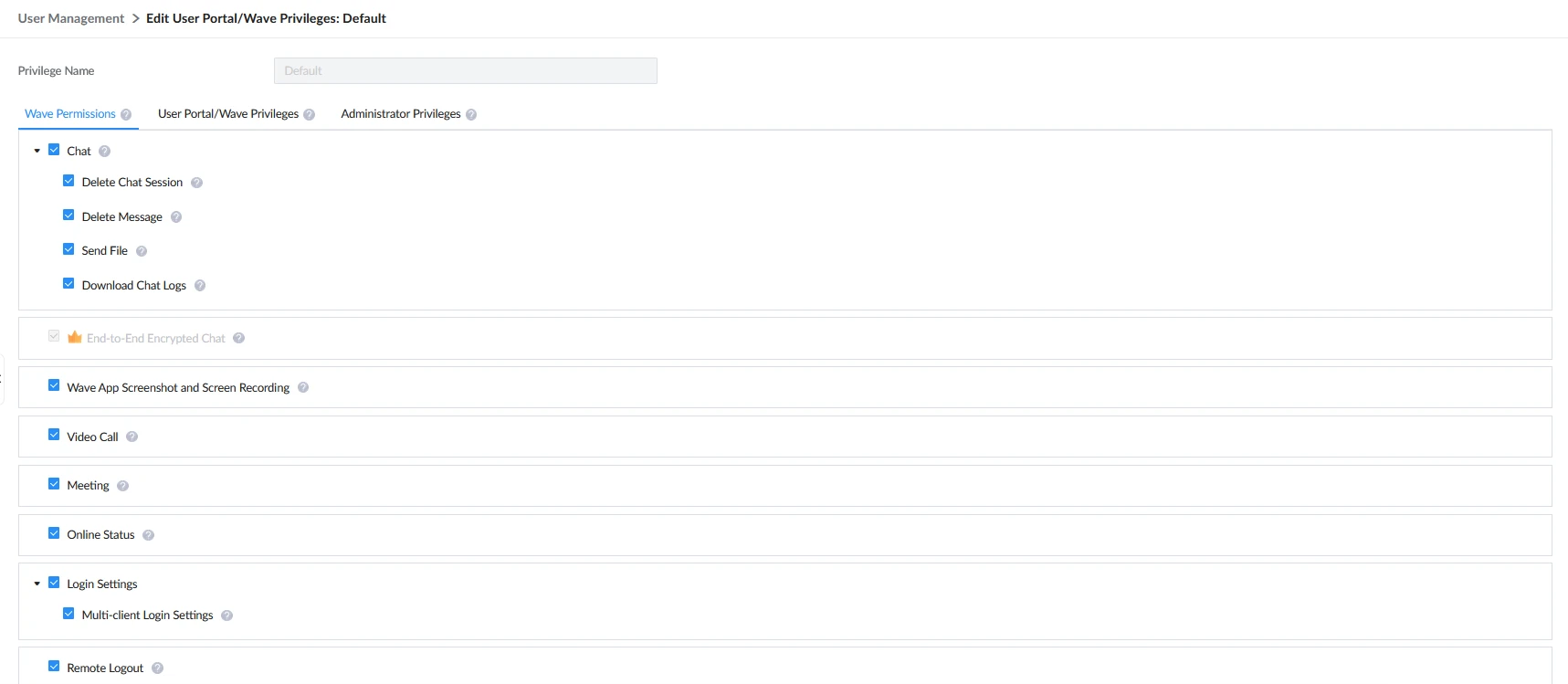
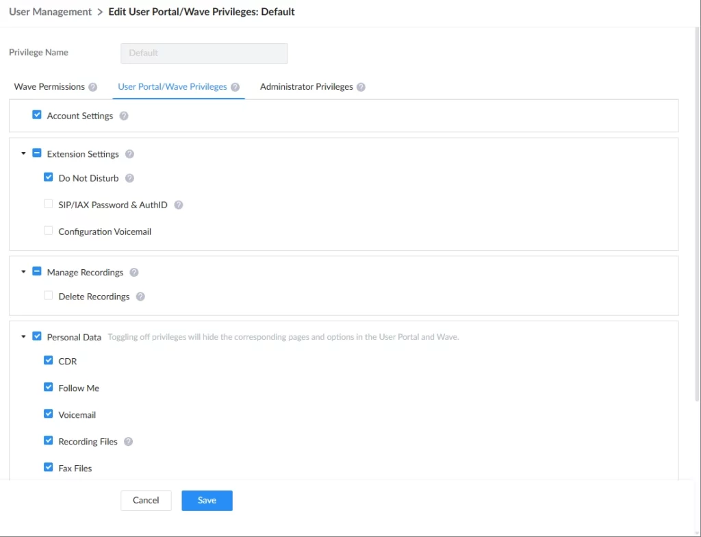
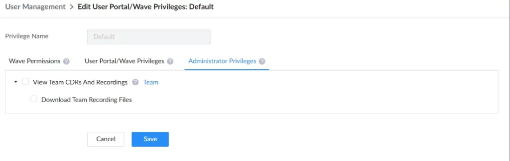
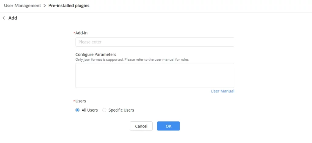
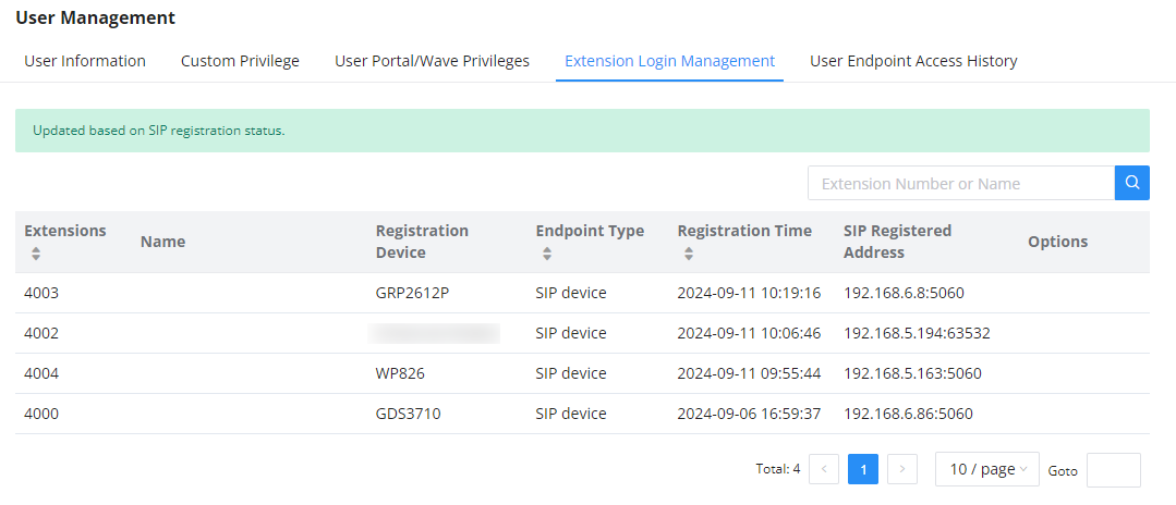
 to terminate a Wave session. SIP sessions cannot be logged out.
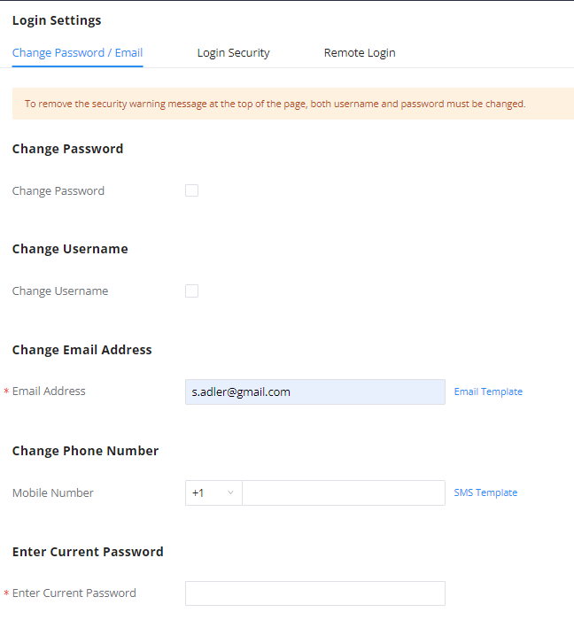
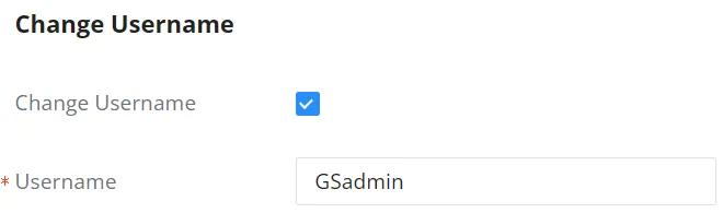

 under banned users.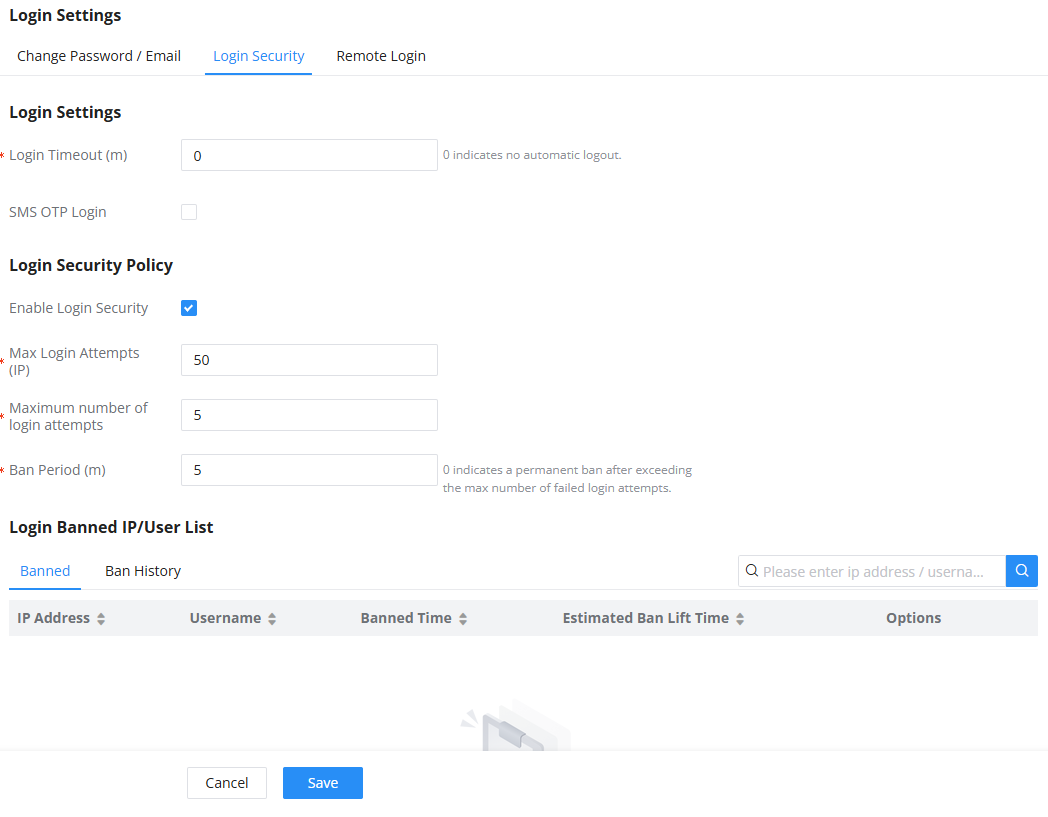
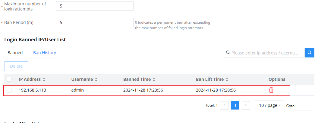
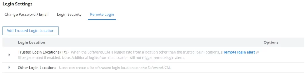

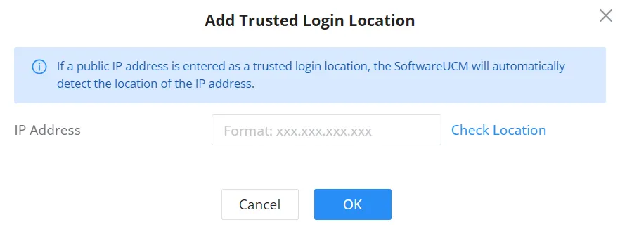
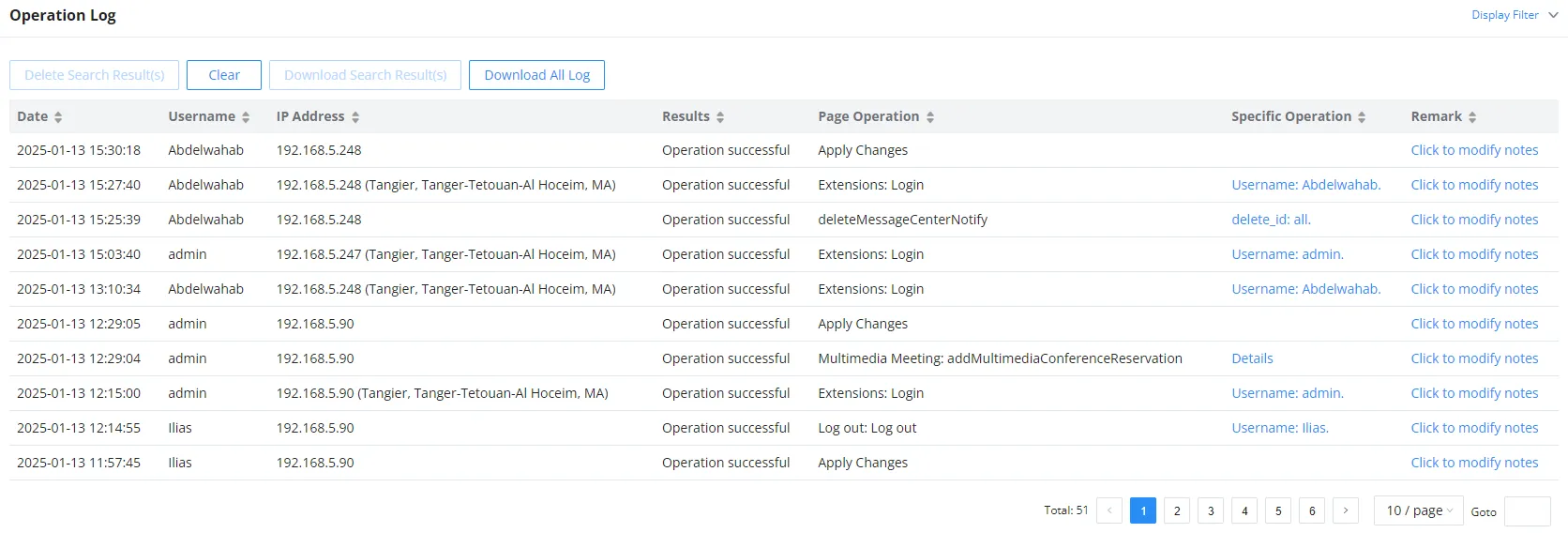
 or
or  at the top of each column to sort. For example, clicking on
  for “Date” will sort the logs according to newer operation date and time. Clicking on
  for “Date” will reverse the order.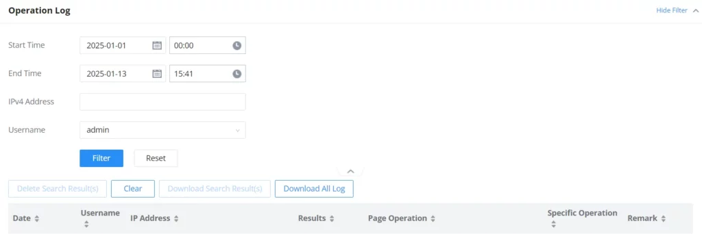
 to delete the filtered result of operation logs. Or users can click on
  to delete all operation logs at once.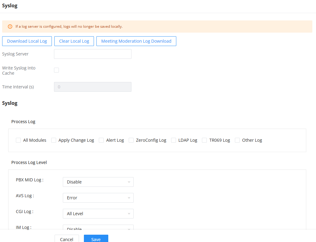
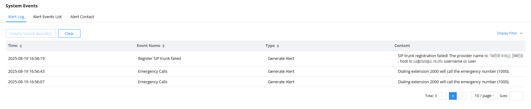
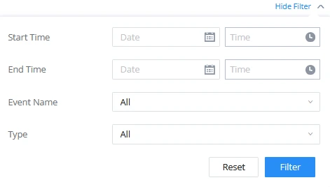
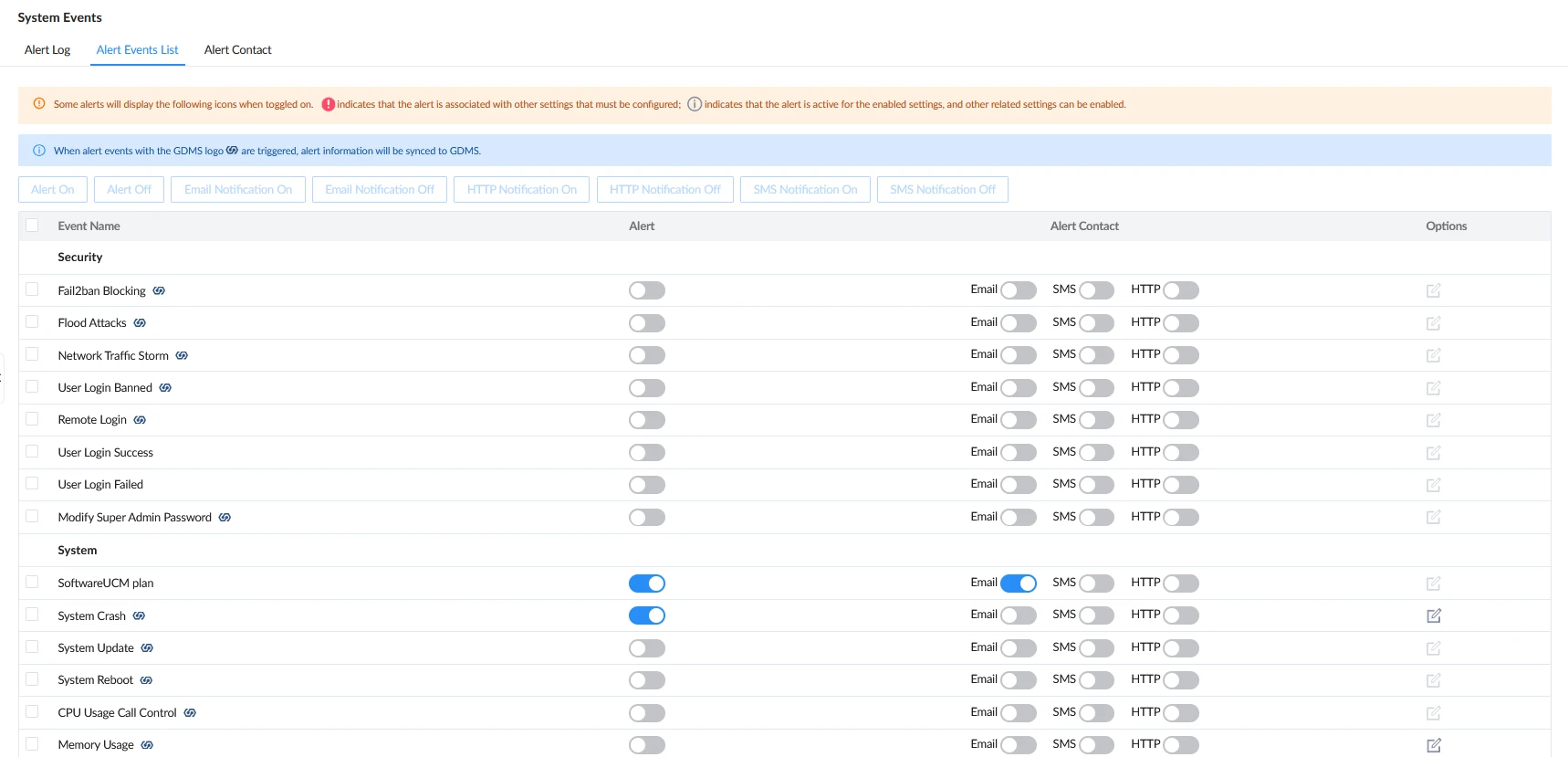
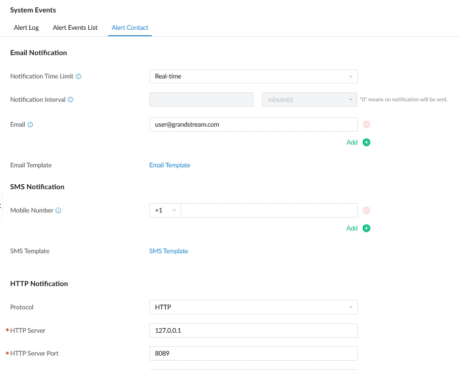
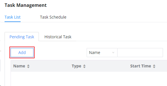
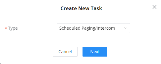
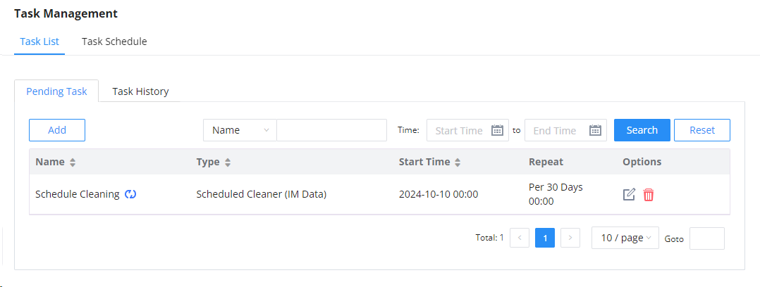
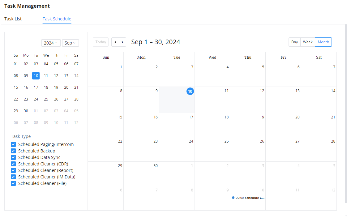
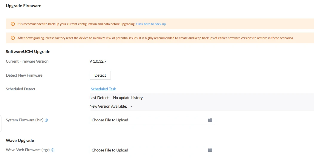
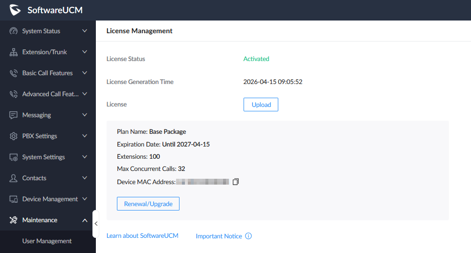
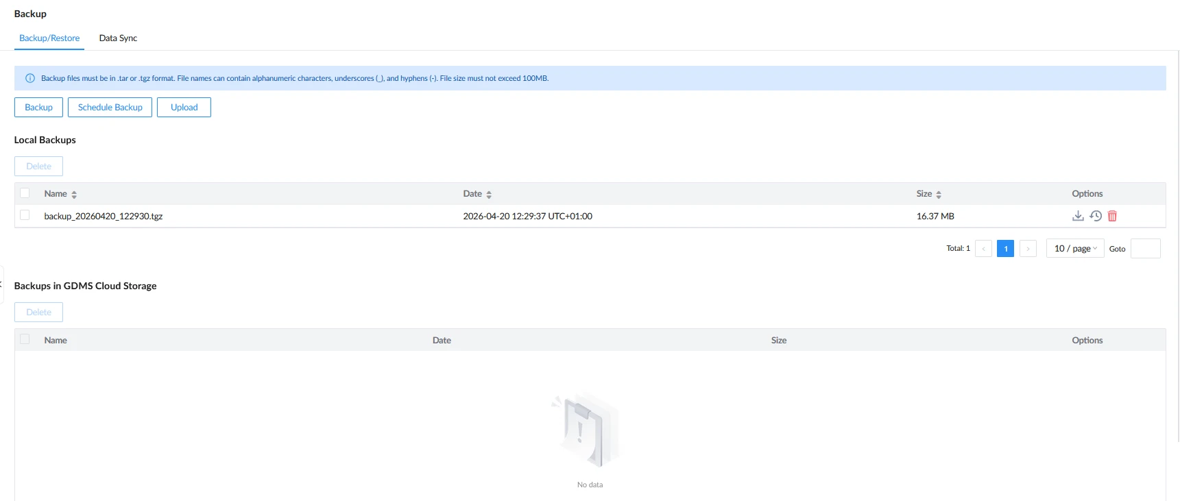
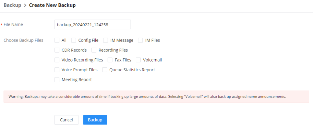
 , restore
  , or delete
  it from the SoftwareUCM internal storage or the external device.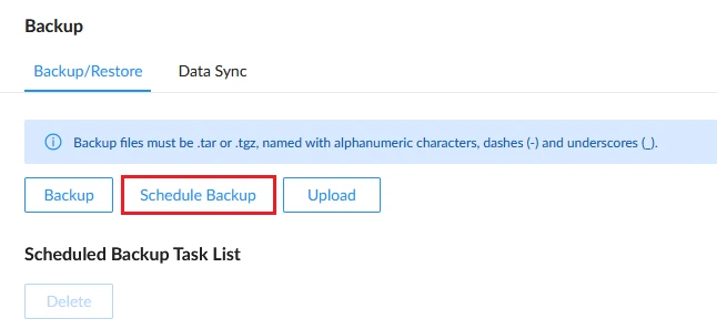
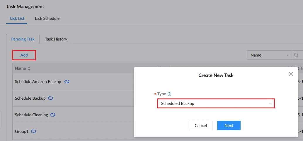
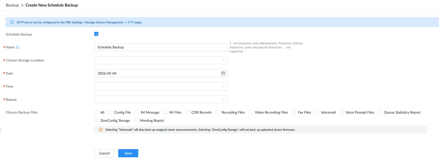
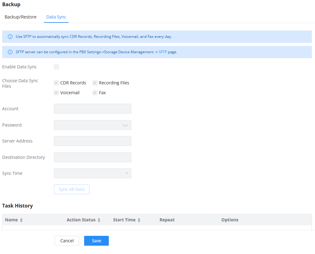
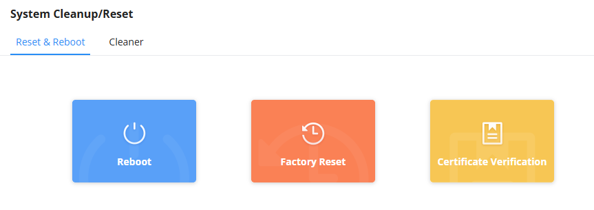
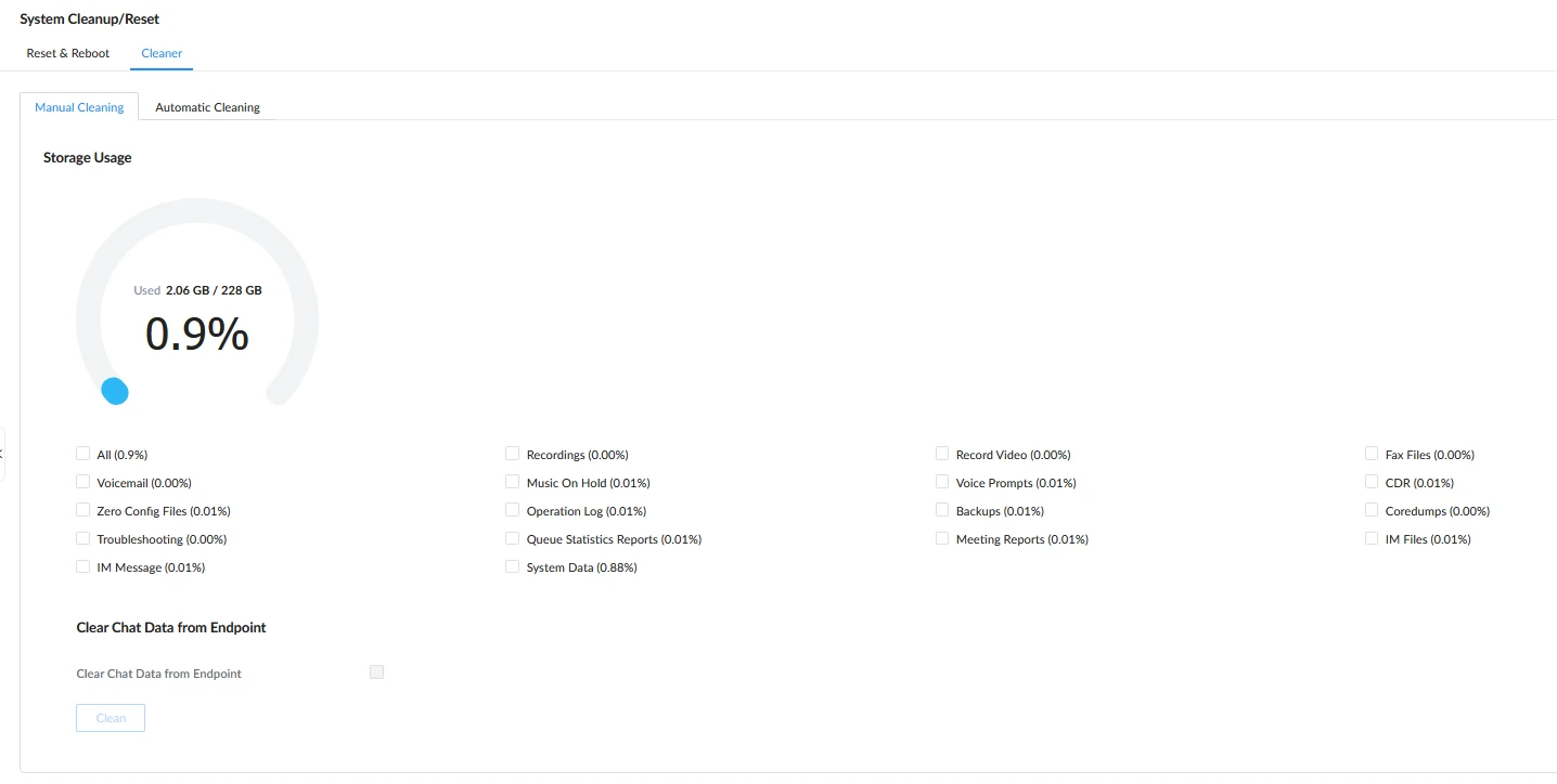
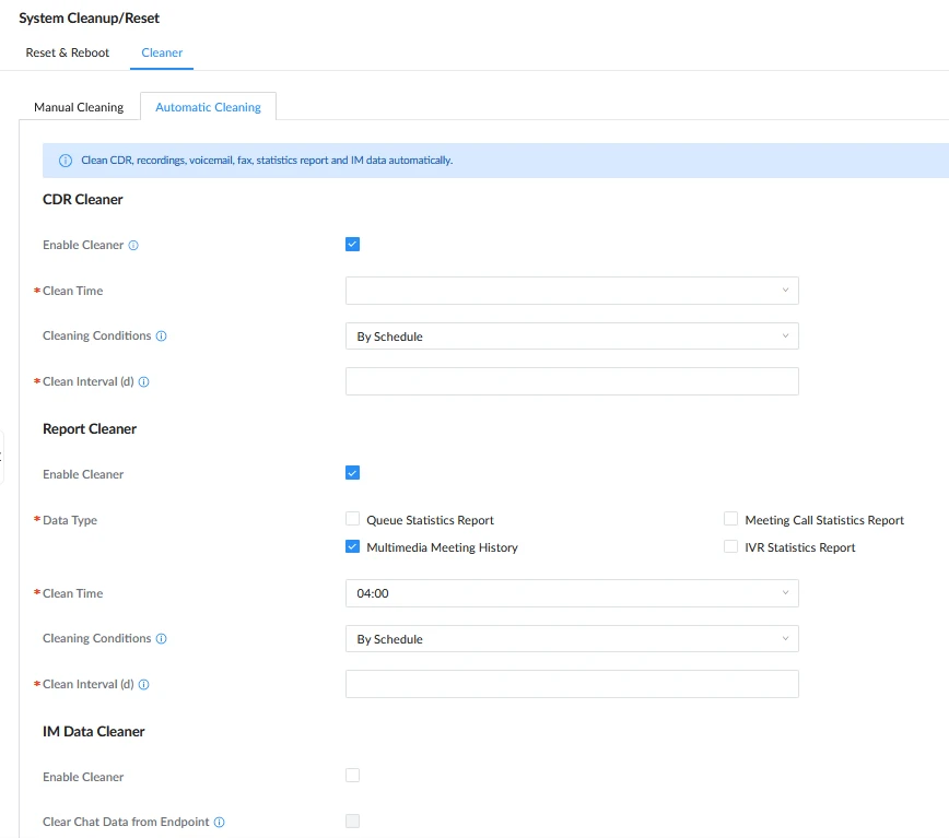
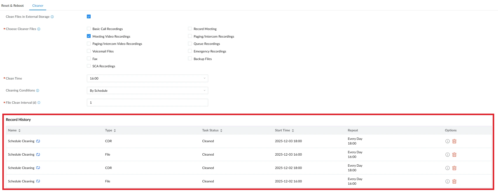
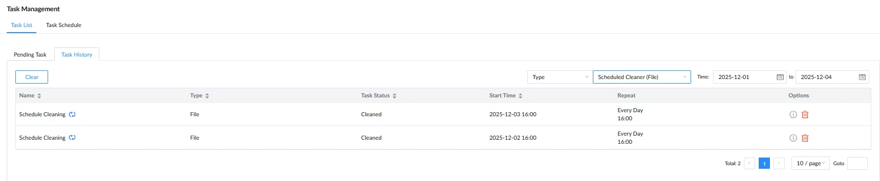
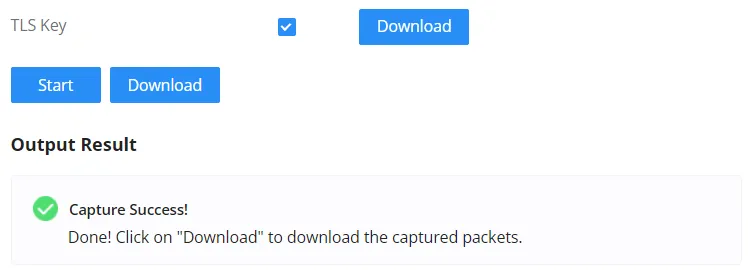
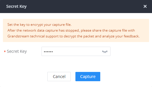

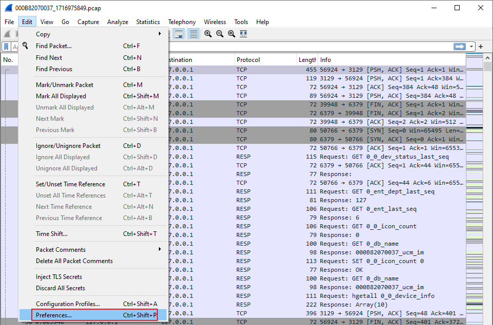
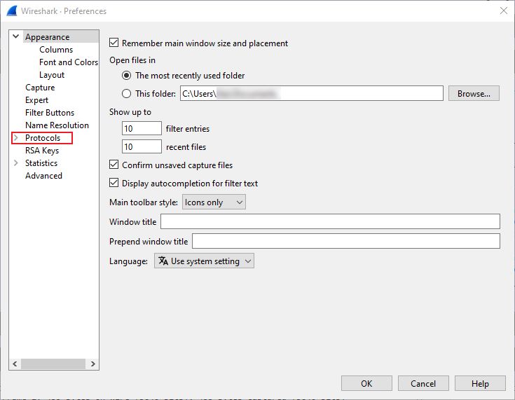

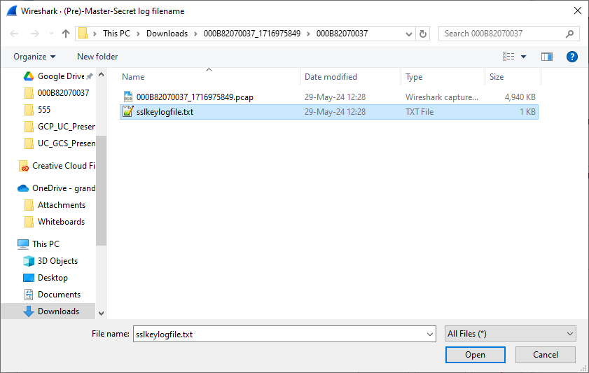
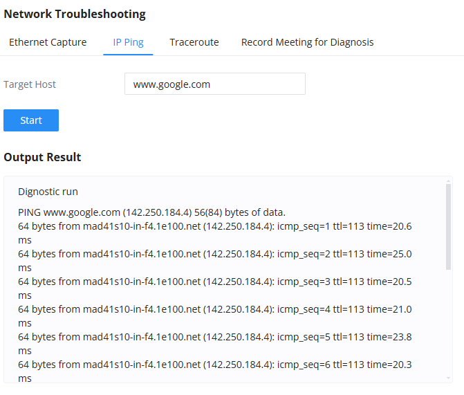
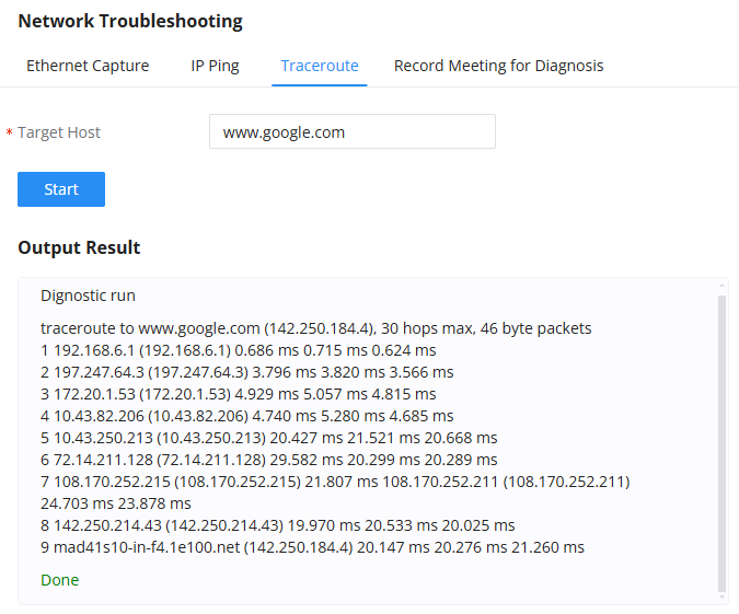
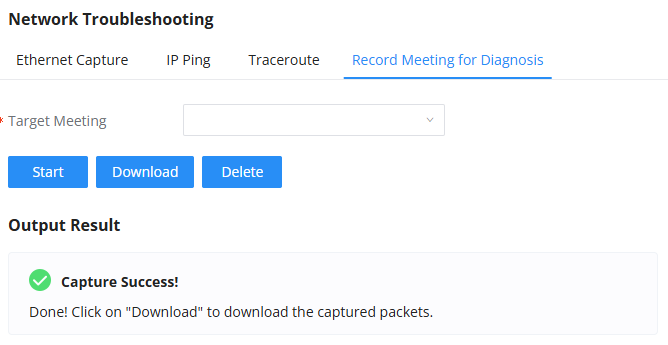
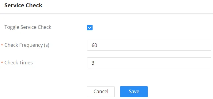
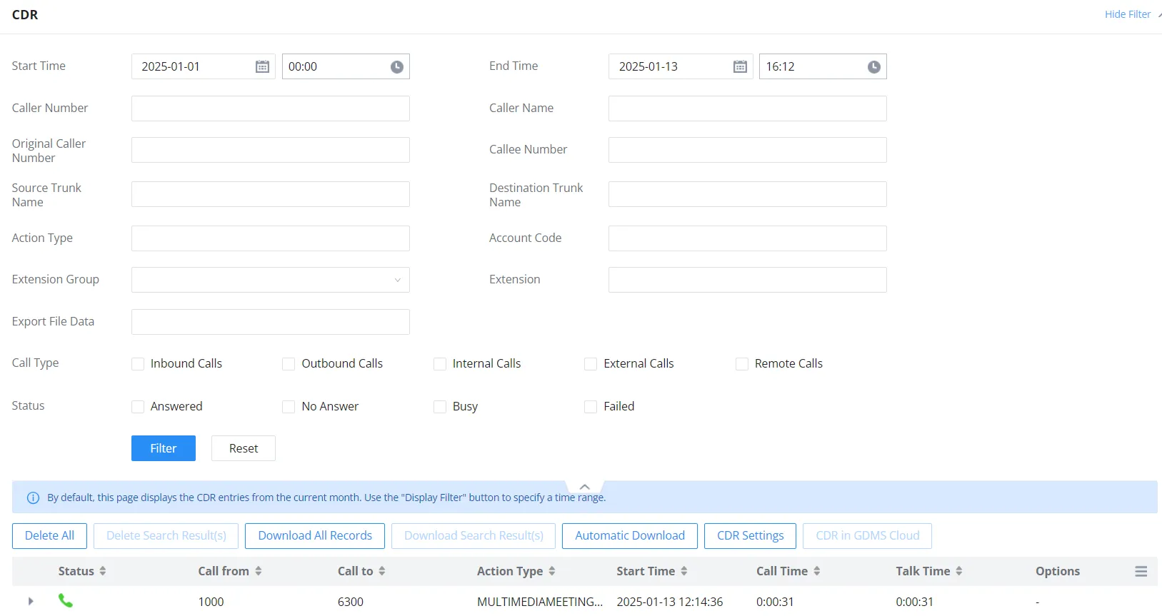

 button to remove all the call report information.
 button to remove CDR records that
 to play the recording file; click on
 to download the recording file in .wav format; click on
 to delete the recording file (the call record entry will not be deleted).
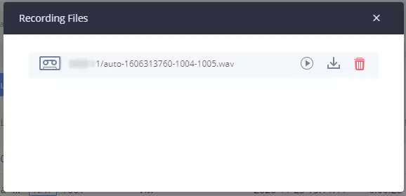
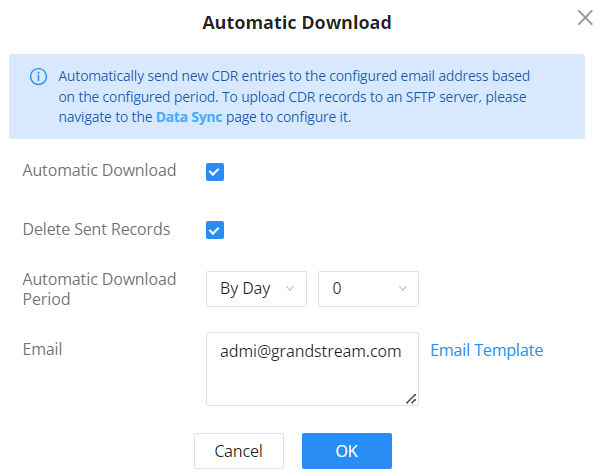




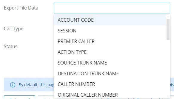
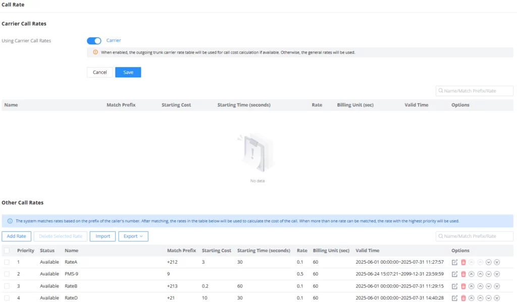
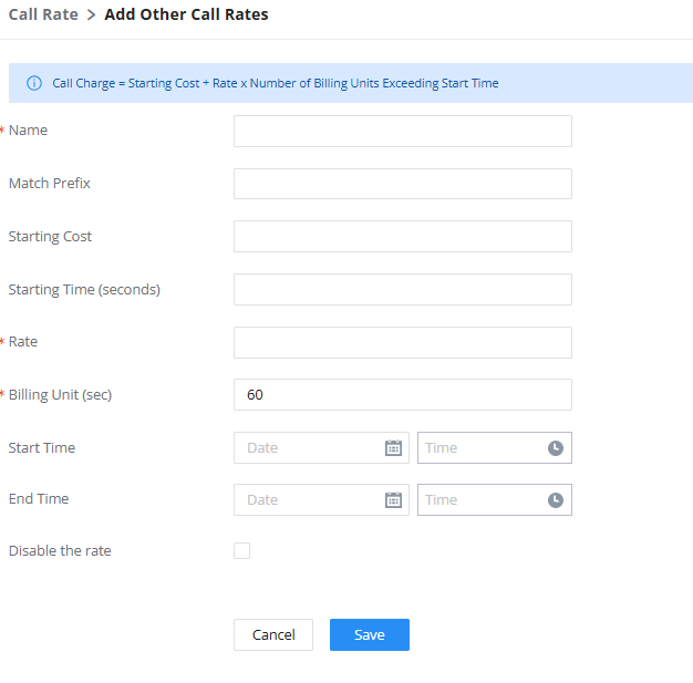
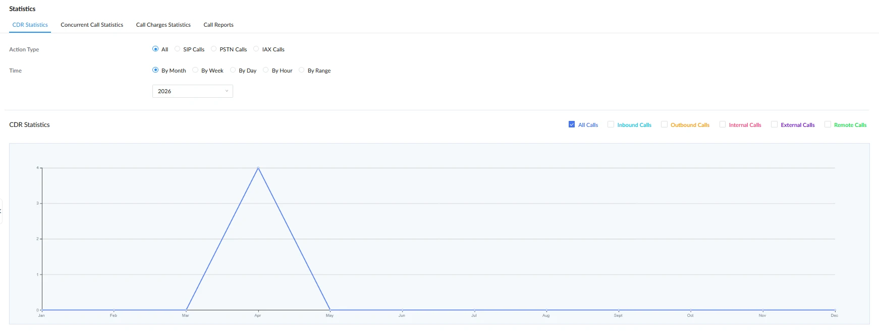
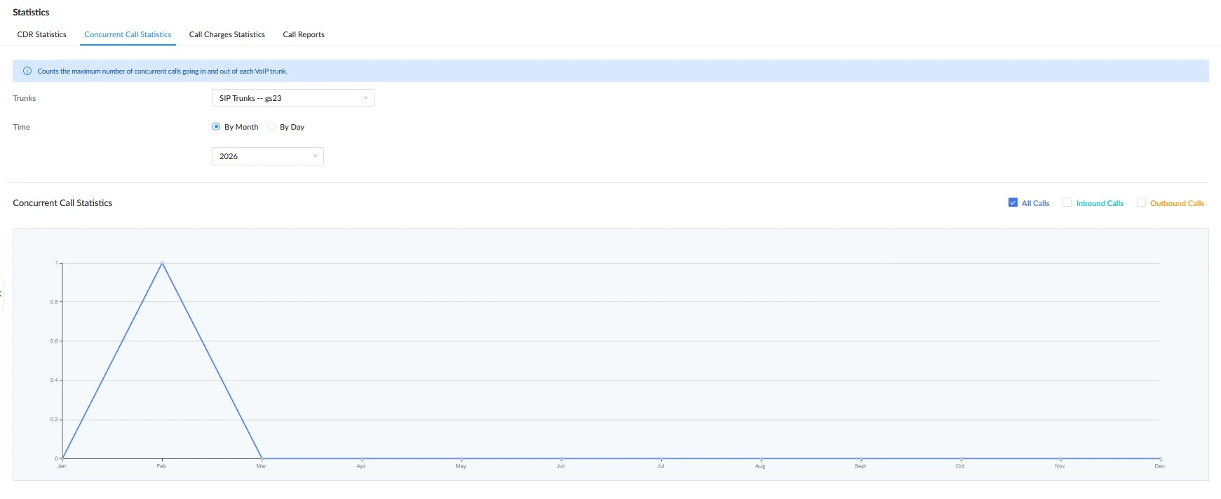
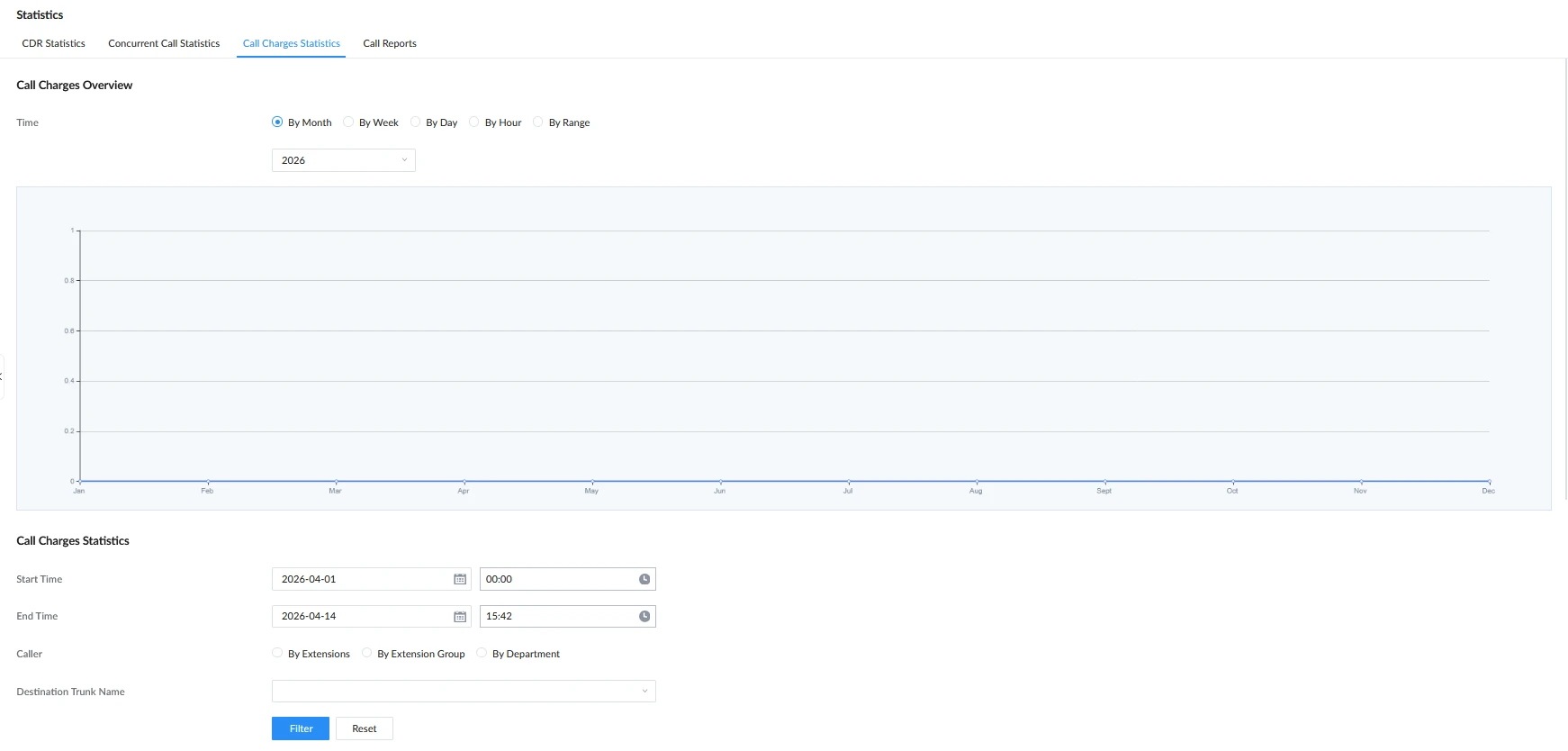
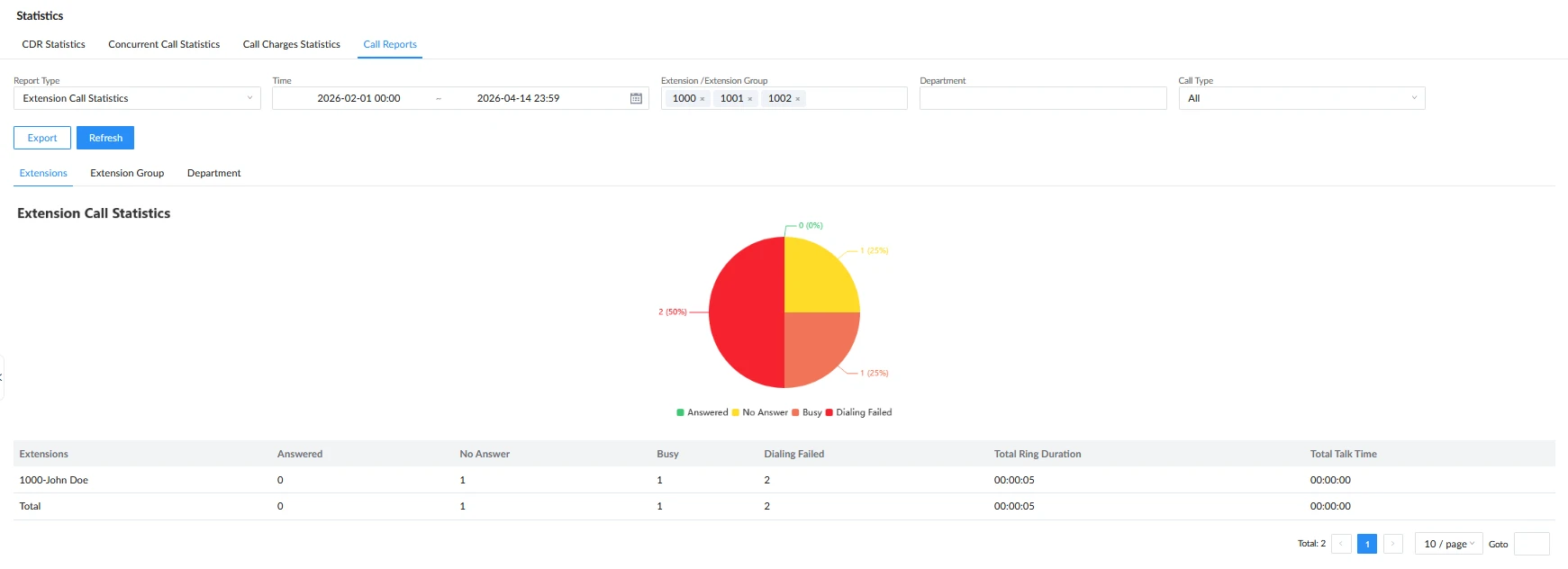
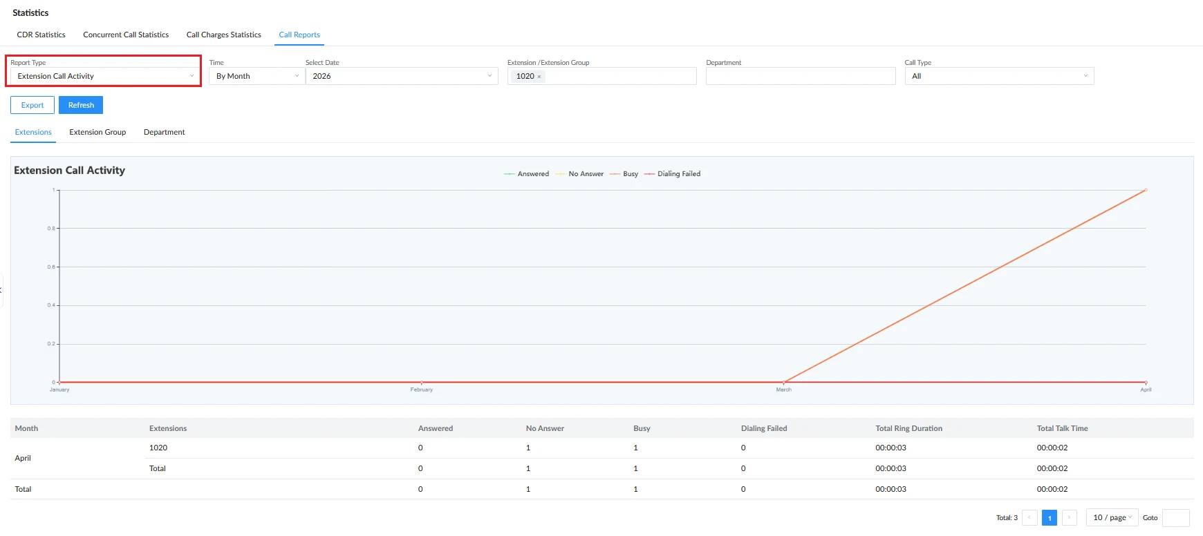
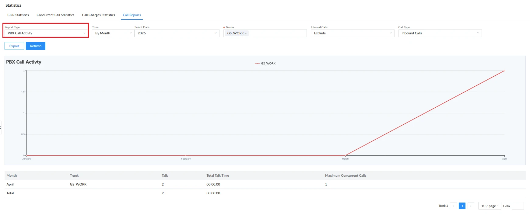
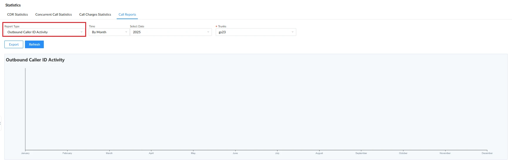
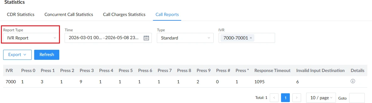
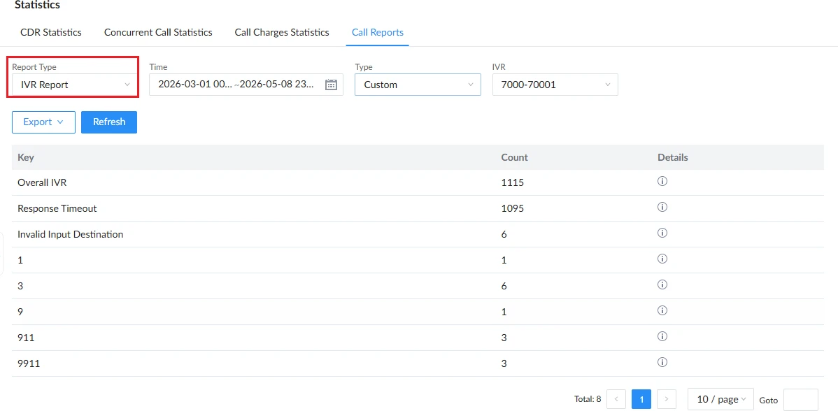

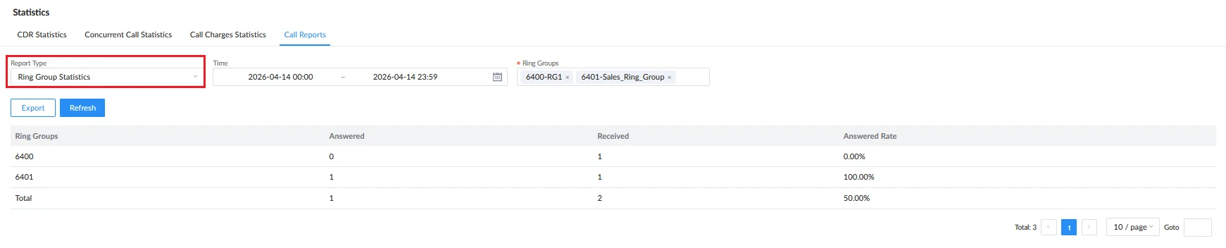
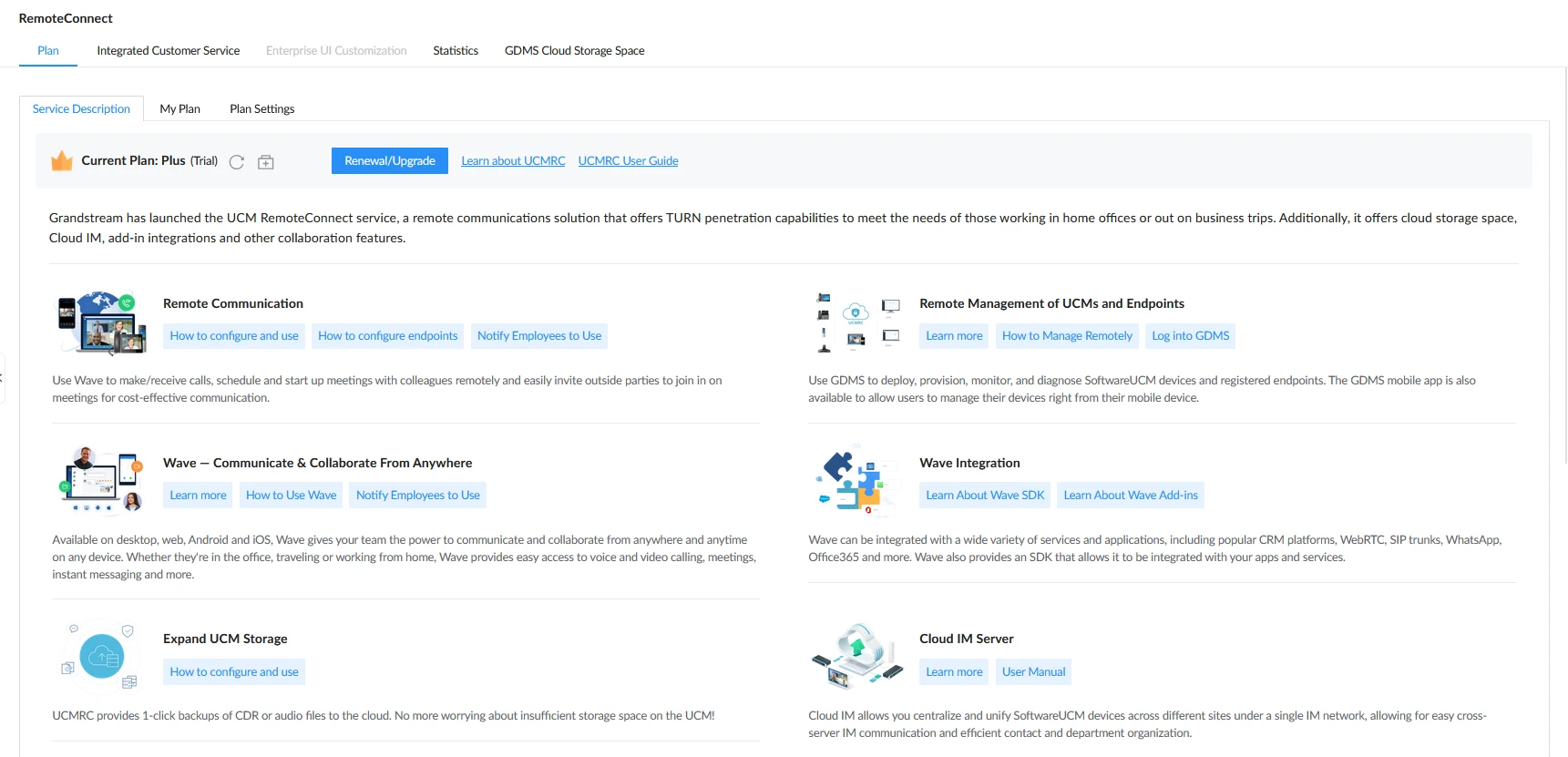
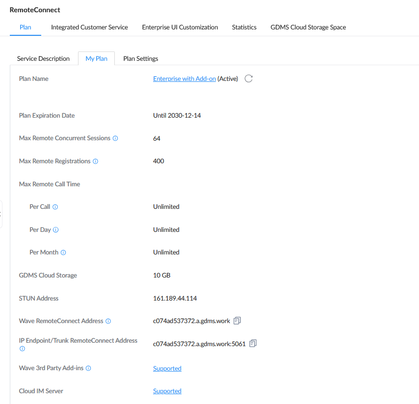
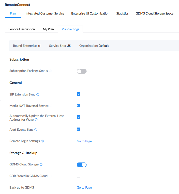
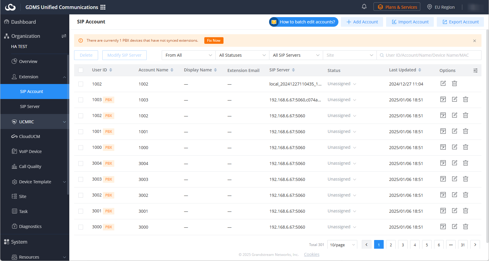
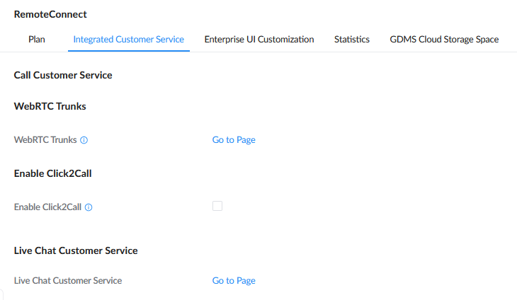
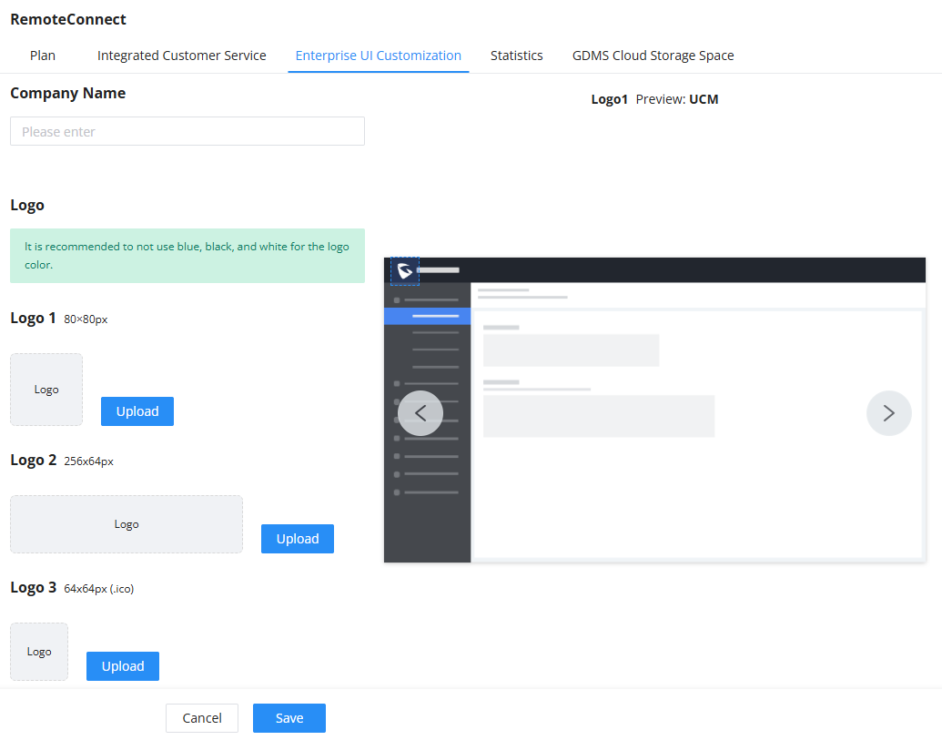
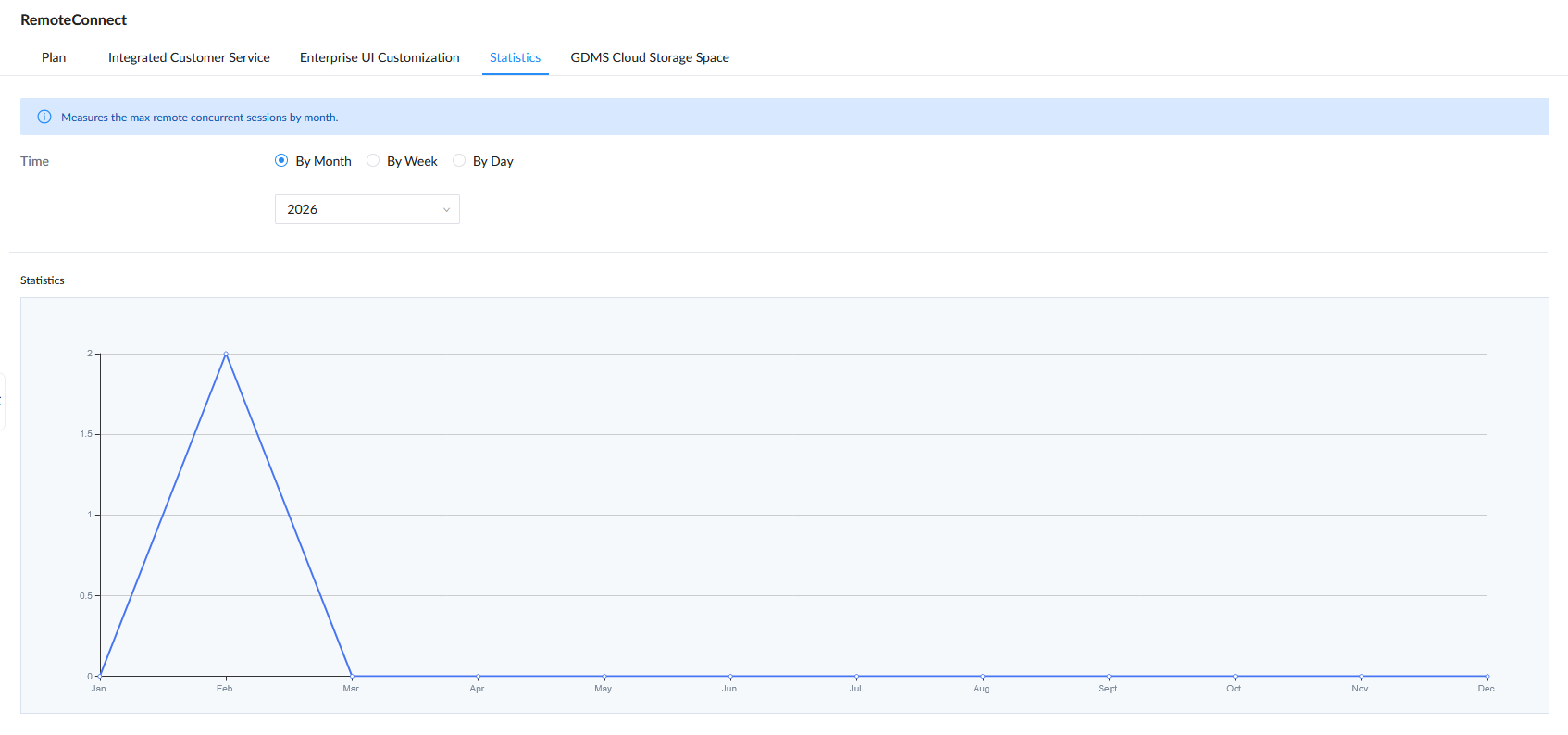
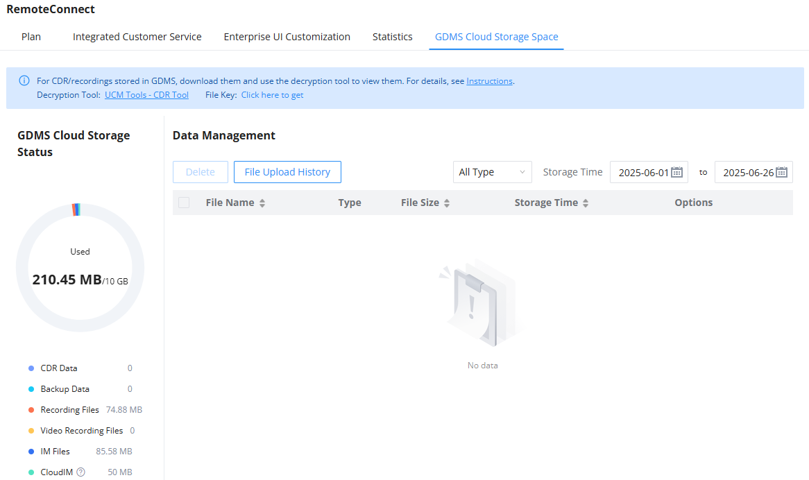

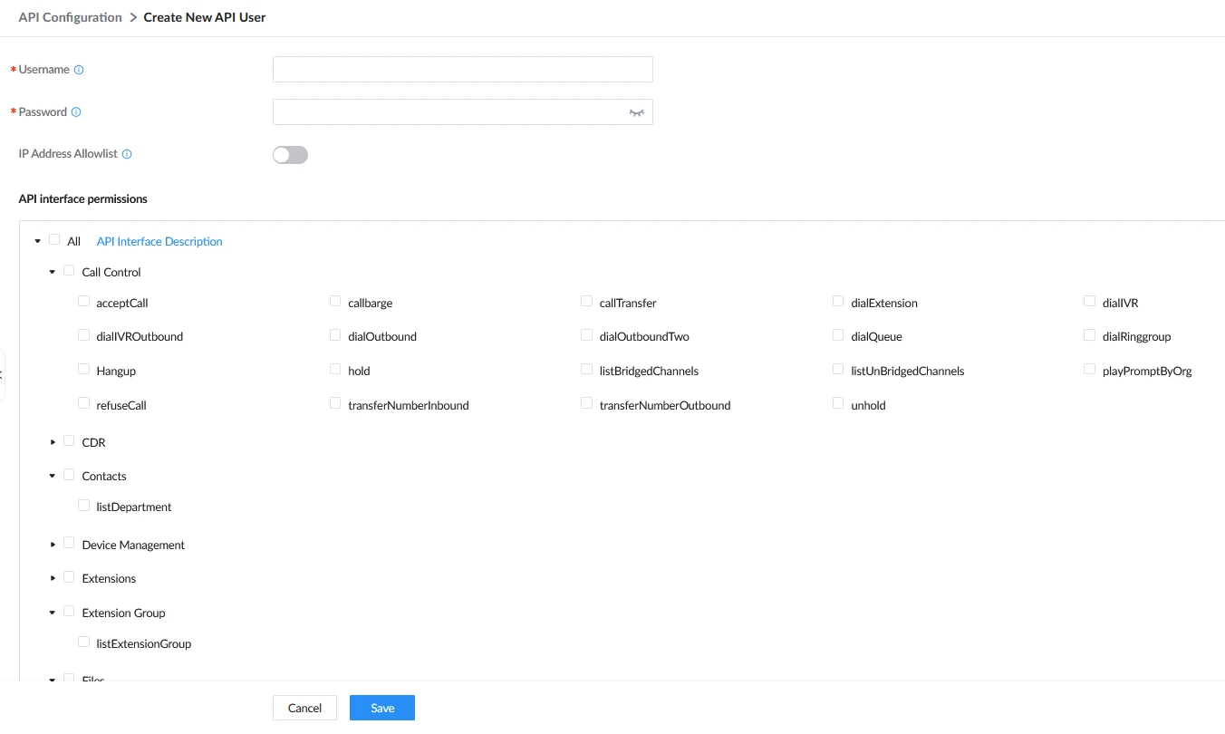
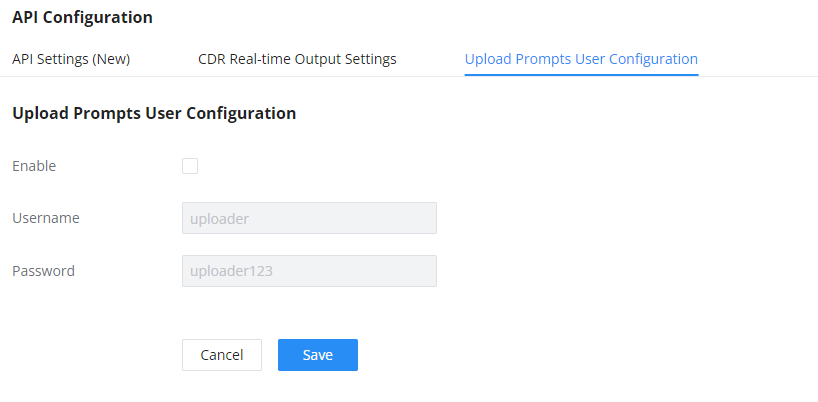

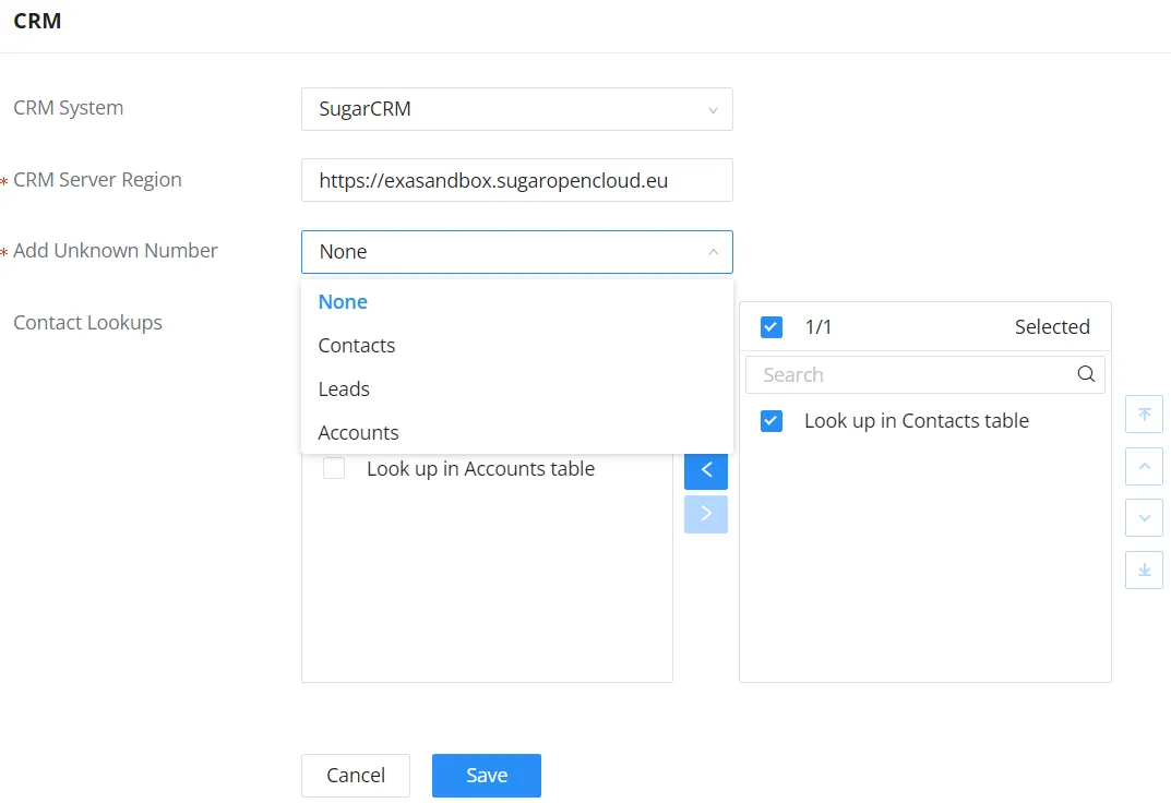

 to select where the UCM can perform the lookups on the CRM tables, Leads, Accounts, and Contacts.


 and
and
 . The status will change from “Logged Out” to “Logged In”. User can start then using SugarCRM features.
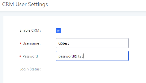
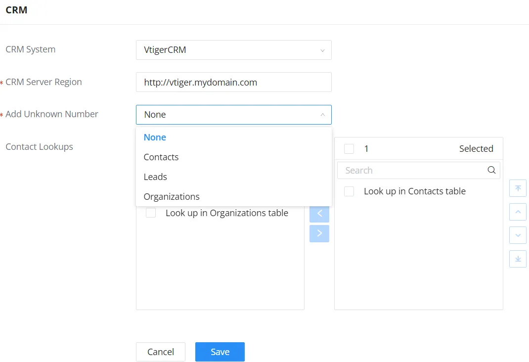

 to select where the UCM can perform the lookups on the CRM tables, Leads, Organizations, and Contacts.


 and
and  . The status will change from “Logged Out” to “Logged In”. User can start then using SugarCRM features.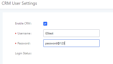
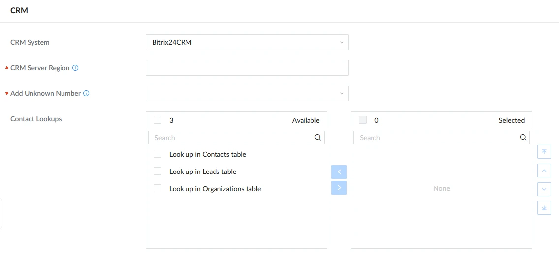
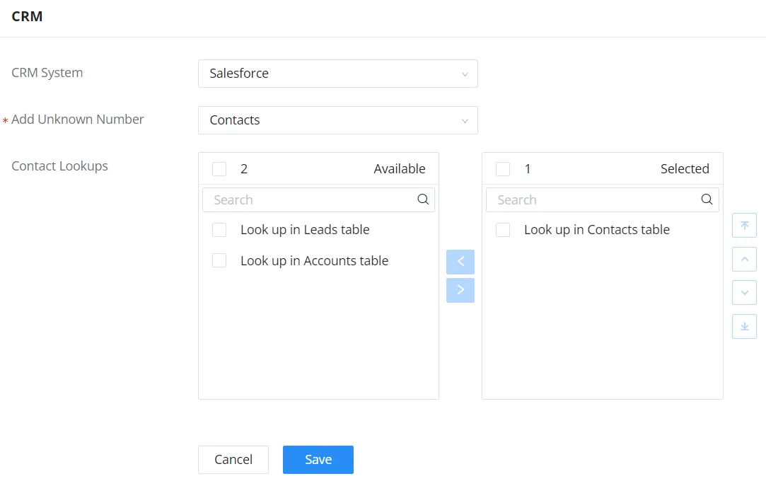

 to select where the UCM can perform the lookups on the CRM tables, Leads, Accounts, and Contacts.


 and
and  . The status will change from “Logged Out” to “Logged In”. User can start then using Salesforce CRM features.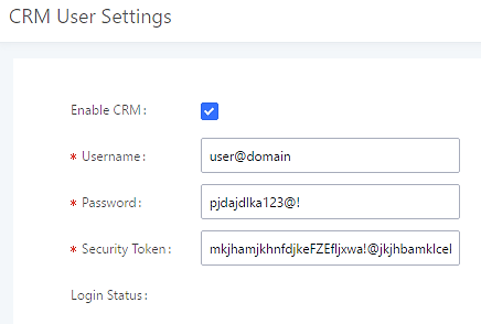
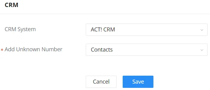
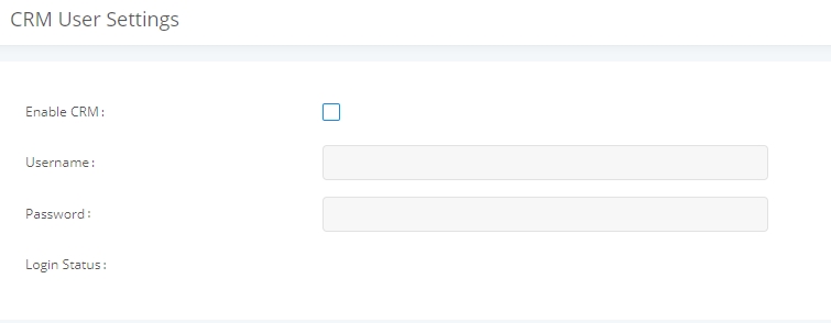
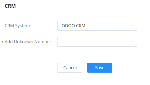
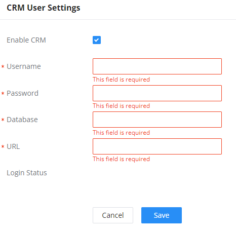
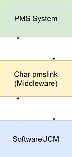
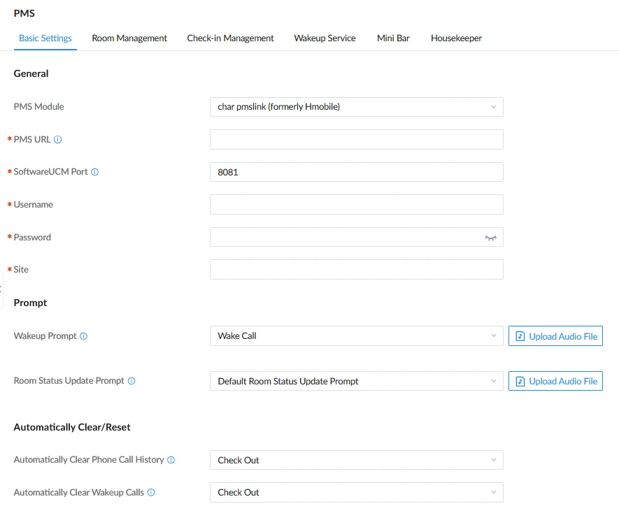
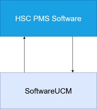
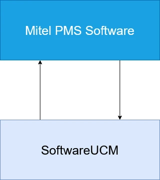

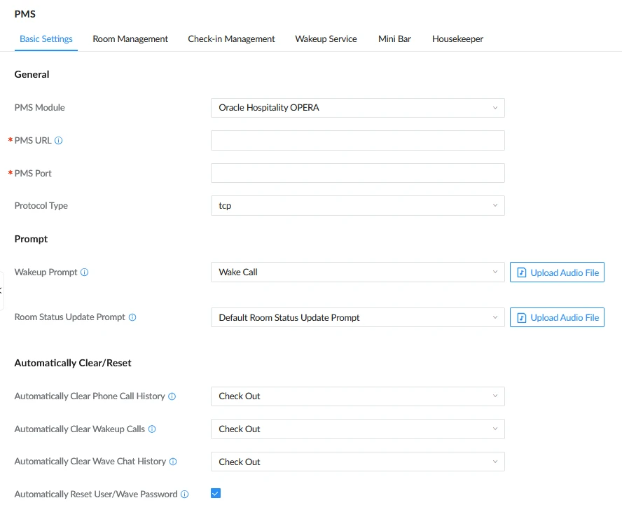
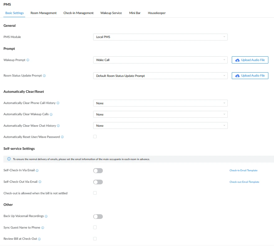
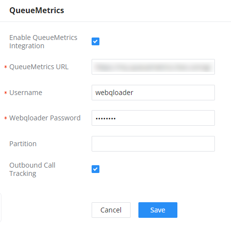
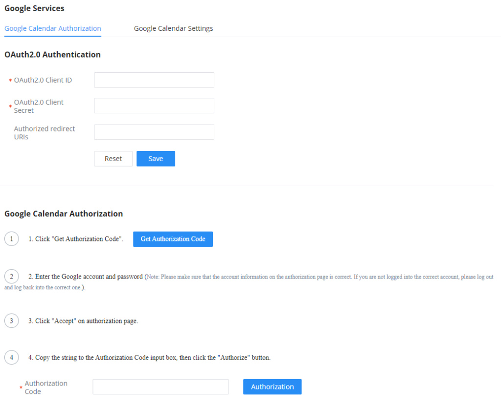
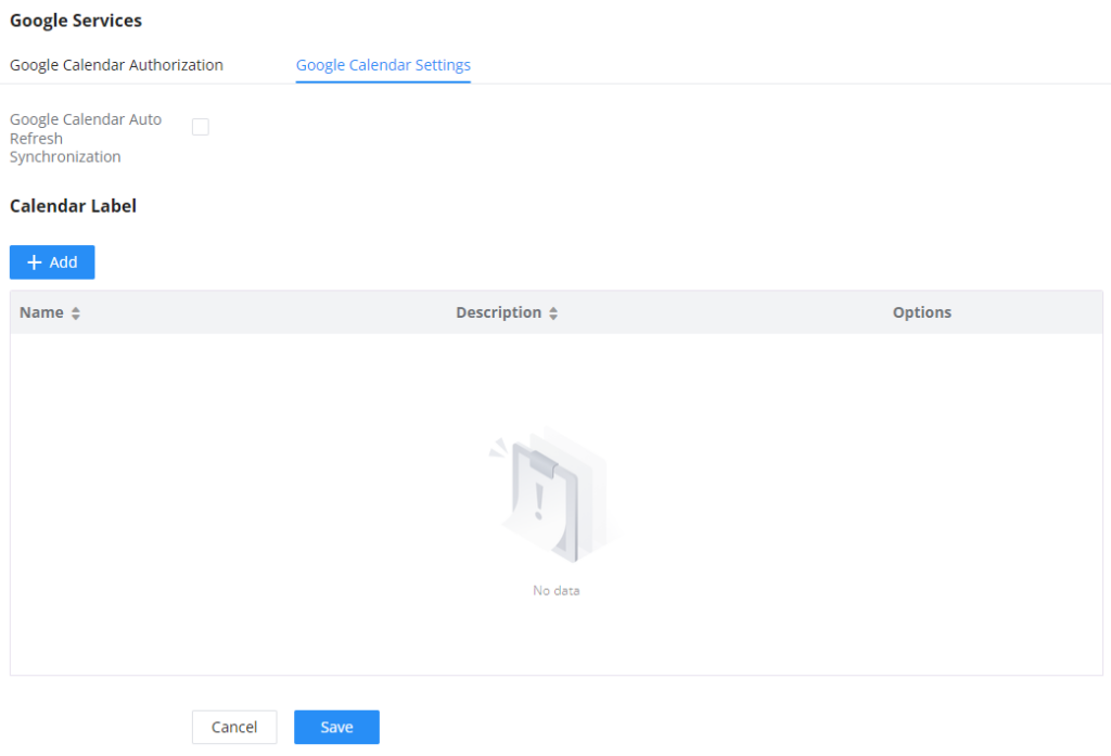
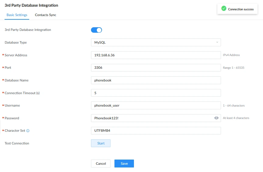
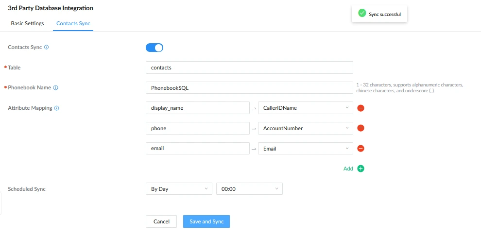
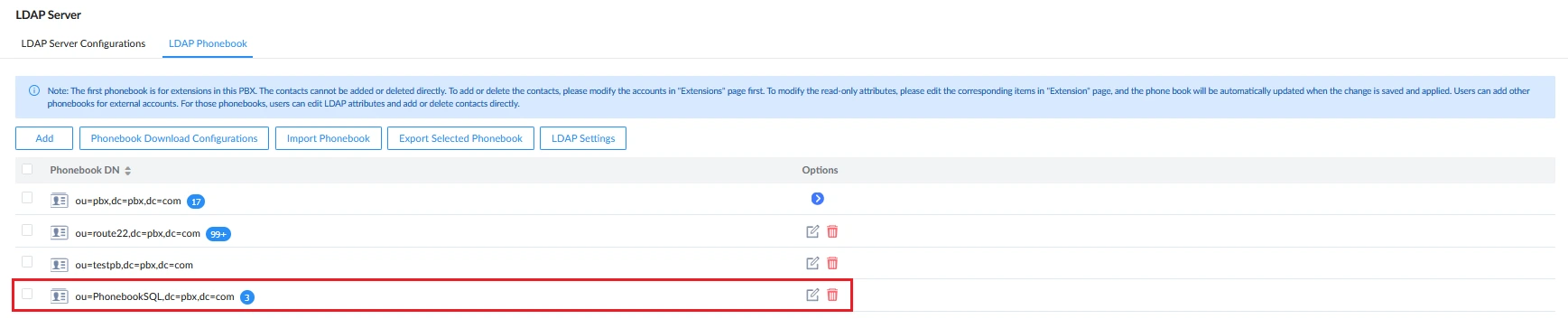

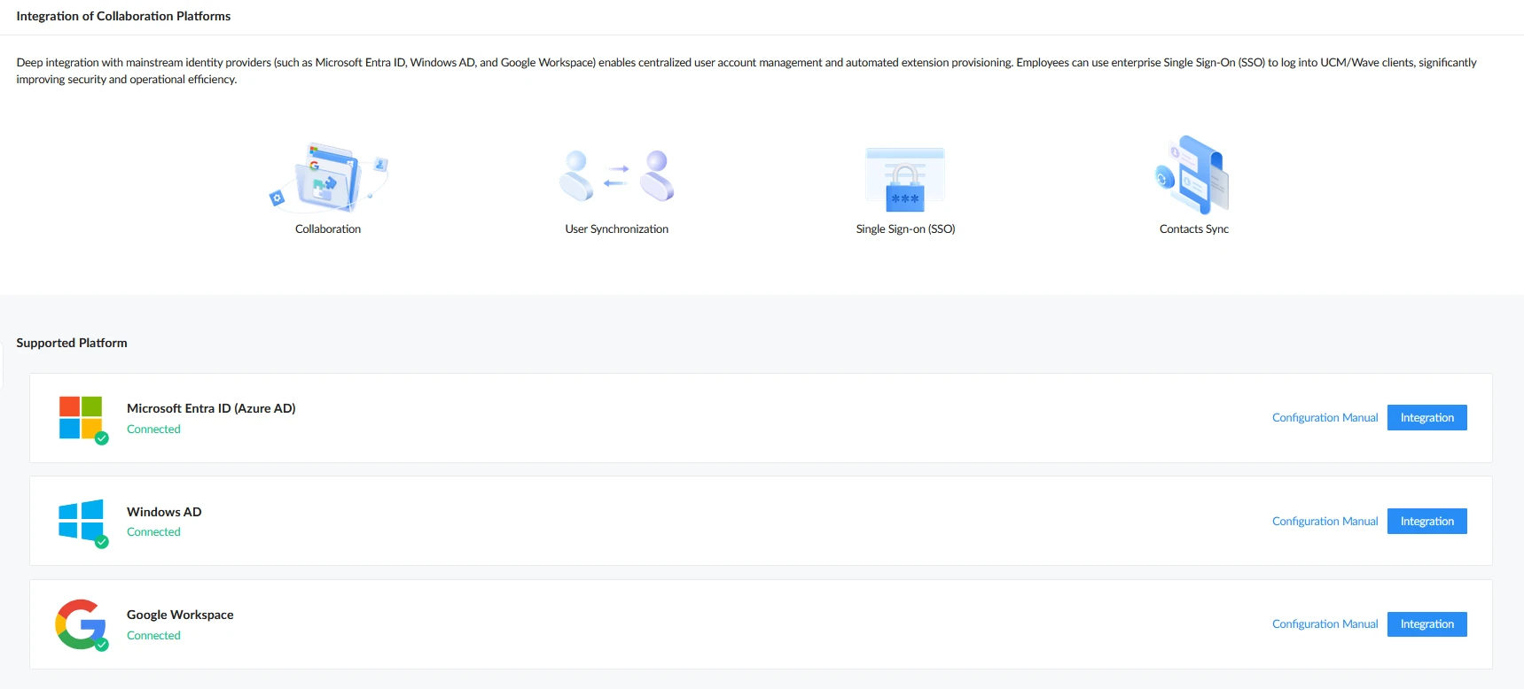
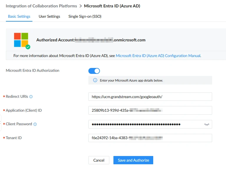
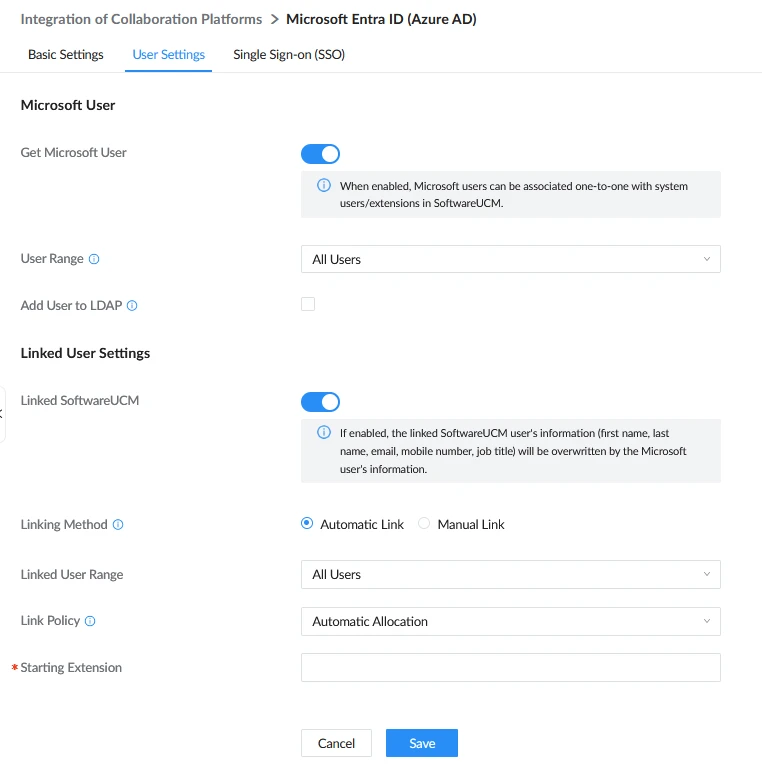
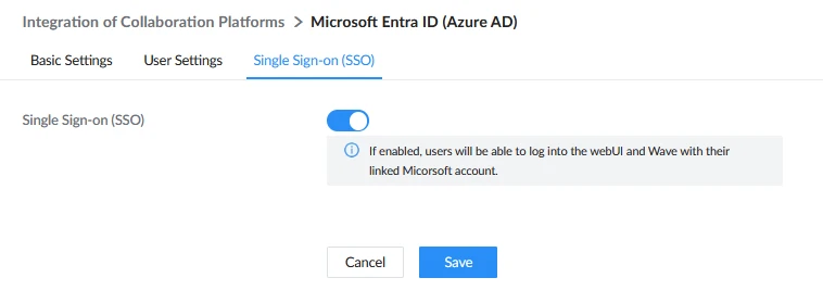

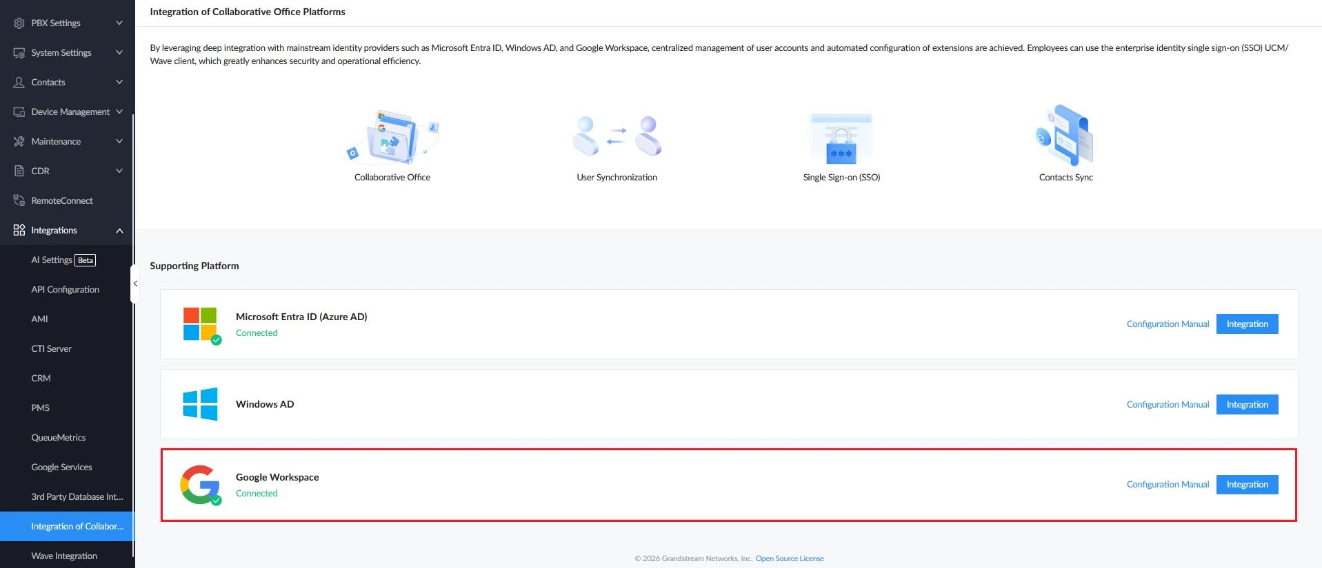
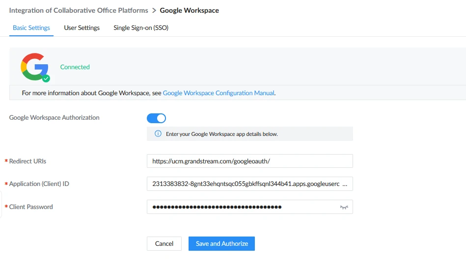
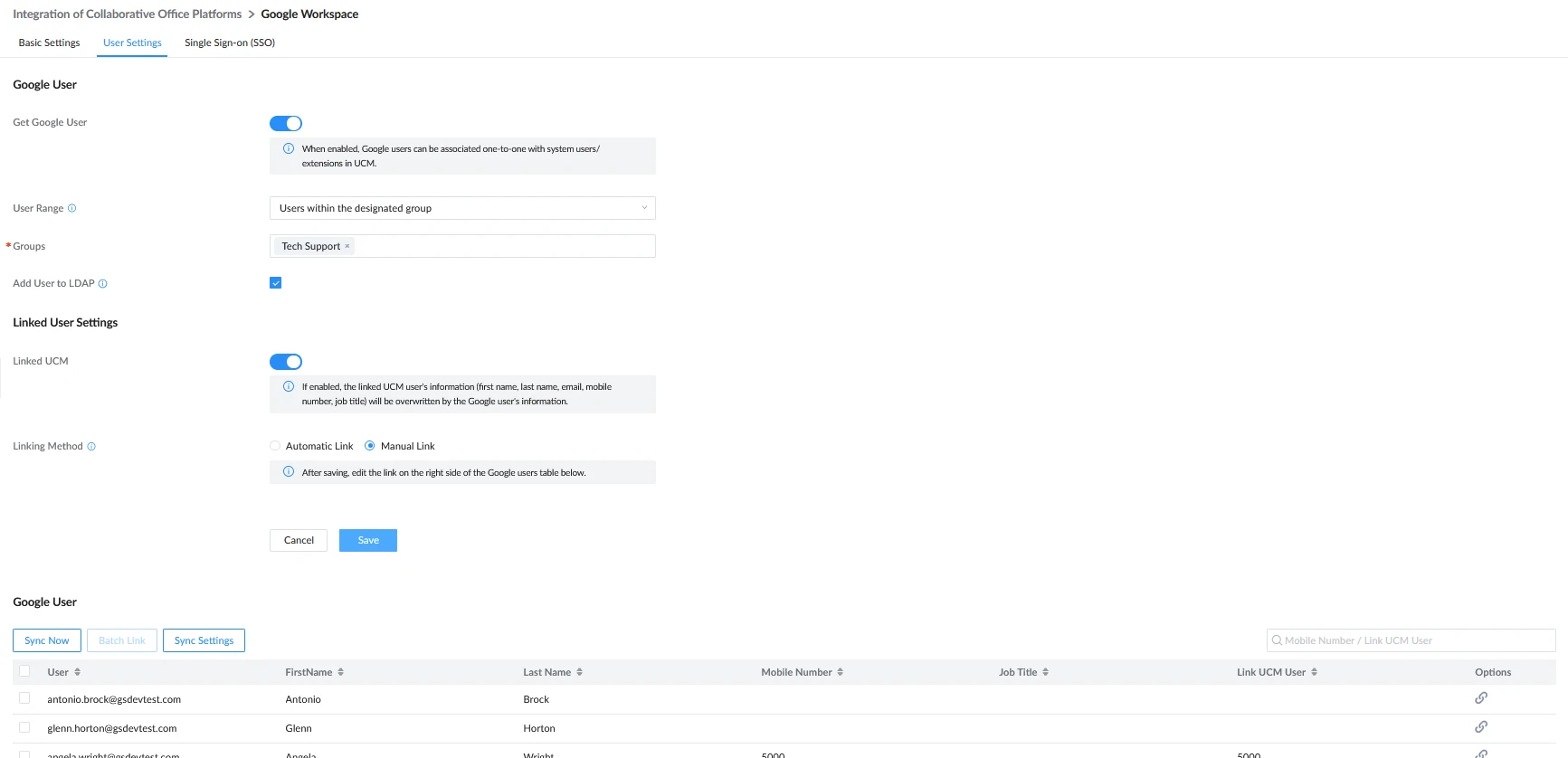
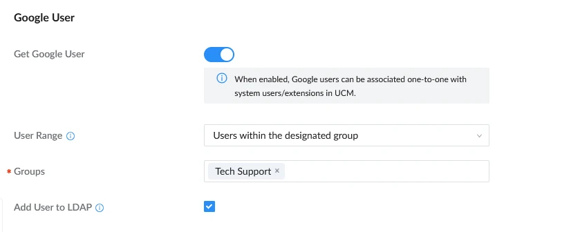
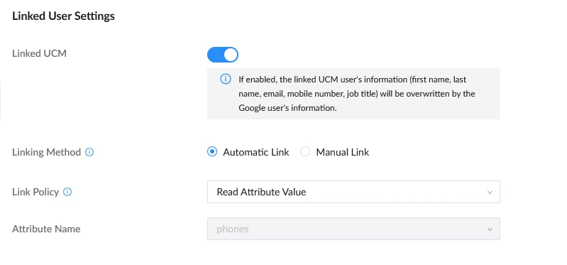

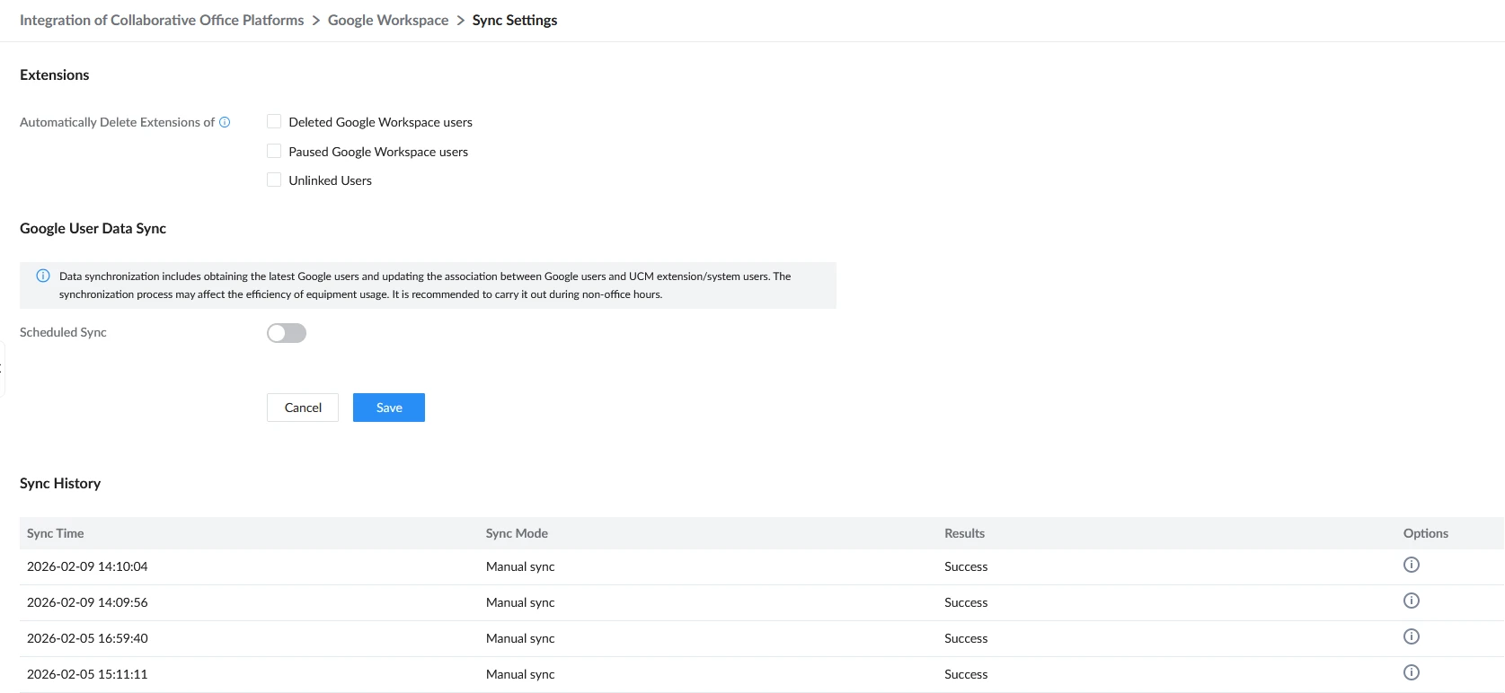
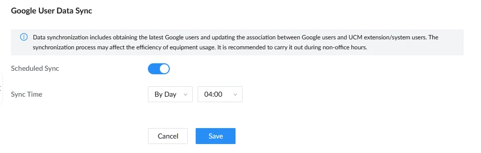
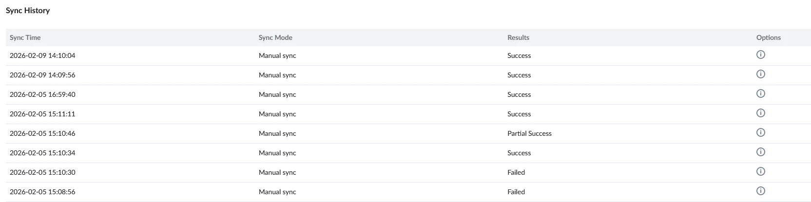
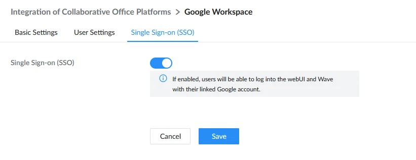
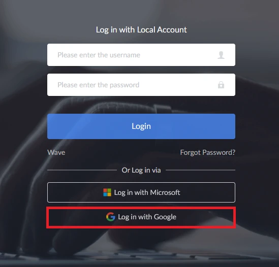
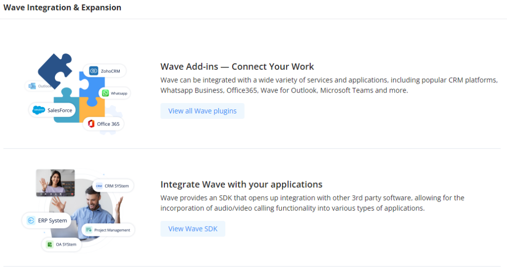
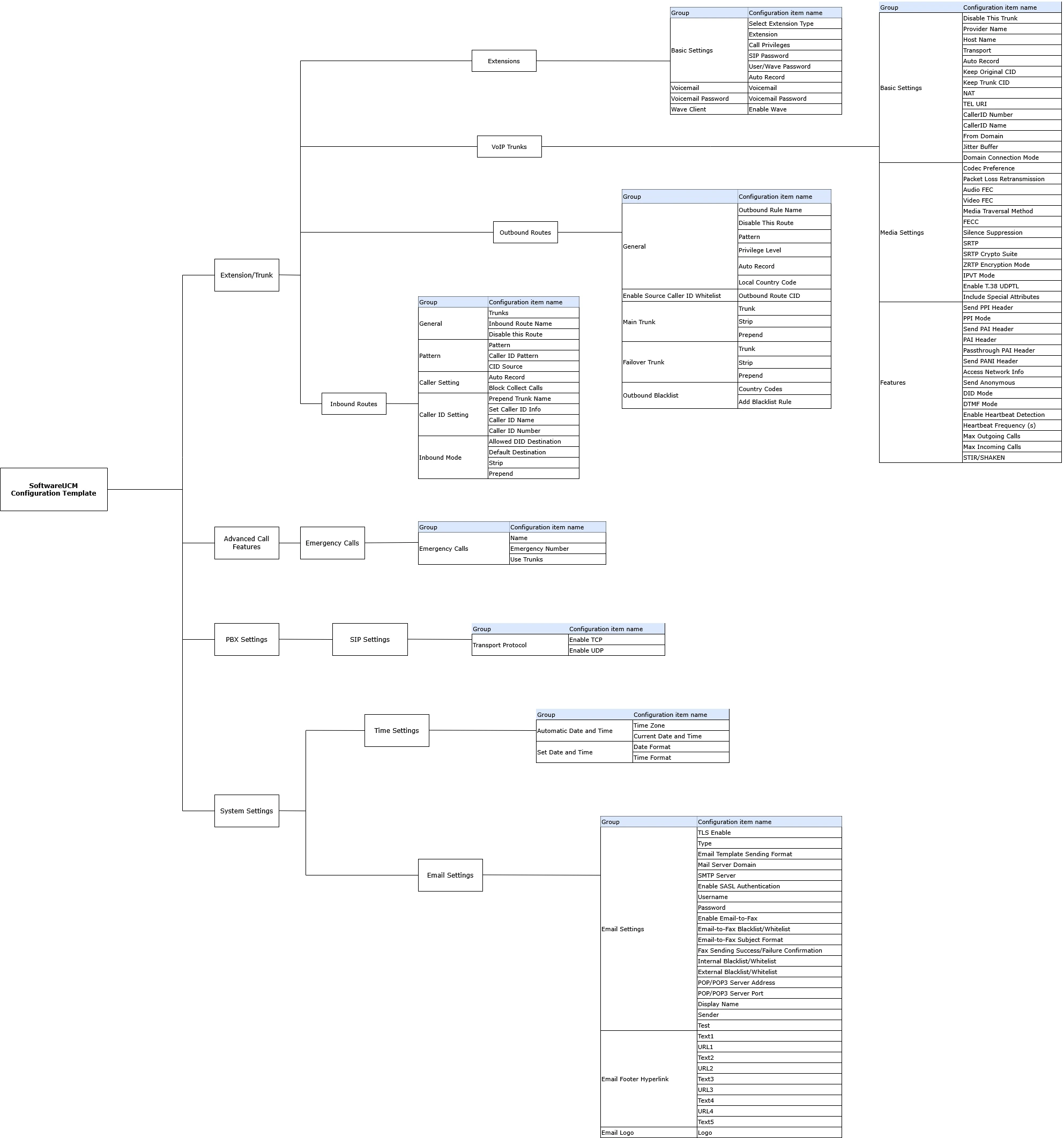
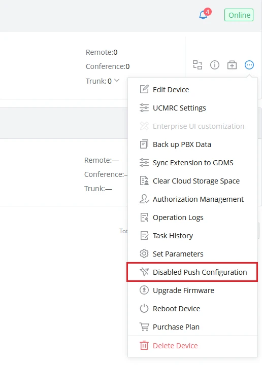
 Go to Organization → Device Template → By Model and click on
  Go to Organization → Device Template → By Model and click on